JP4495970B2 - Method and apparatus for densification of substrate by chemical vapor infiltration - Google Patents
Method and apparatus for densification of substrate by chemical vapor infiltration Download PDFInfo
- Publication number
- JP4495970B2 JP4495970B2 JP2003560261A JP2003560261A JP4495970B2 JP 4495970 B2 JP4495970 B2 JP 4495970B2 JP 2003560261 A JP2003560261 A JP 2003560261A JP 2003560261 A JP2003560261 A JP 2003560261A JP 4495970 B2 JP4495970 B2 JP 4495970B2
- Authority
- JP
- Japan
- Prior art keywords
- duct
- housing
- longitudinal end
- reaction gas
- inlet
- Prior art date
- Legal status (The legal status is an assumption and is not a legal conclusion. Google has not performed a legal analysis and makes no representation as to the accuracy of the status listed.)
- Expired - Lifetime
Links
Images


Classifications
-
- C—CHEMISTRY; METALLURGY
- C23—COATING METALLIC MATERIAL; COATING MATERIAL WITH METALLIC MATERIAL; CHEMICAL SURFACE TREATMENT; DIFFUSION TREATMENT OF METALLIC MATERIAL; COATING BY VACUUM EVAPORATION, BY SPUTTERING, BY ION IMPLANTATION OR BY CHEMICAL VAPOUR DEPOSITION, IN GENERAL; INHIBITING CORROSION OF METALLIC MATERIAL OR INCRUSTATION IN GENERAL
- C23C—COATING METALLIC MATERIAL; COATING MATERIAL WITH METALLIC MATERIAL; SURFACE TREATMENT OF METALLIC MATERIAL BY DIFFUSION INTO THE SURFACE, BY CHEMICAL CONVERSION OR SUBSTITUTION; COATING BY VACUUM EVAPORATION, BY SPUTTERING, BY ION IMPLANTATION OR BY CHEMICAL VAPOUR DEPOSITION, IN GENERAL
- C23C16/00—Chemical coating by decomposition of gaseous compounds, without leaving reaction products of surface material in the coating, i.e. chemical vapour deposition [CVD] processes
- C23C16/04—Coating on selected surface areas, e.g. using masks
- C23C16/045—Coating cavities or hollow spaces, e.g. interior of tubes; Infiltration of porous substrates
-
- C—CHEMISTRY; METALLURGY
- C04—CEMENTS; CONCRETE; ARTIFICIAL STONE; CERAMICS; REFRACTORIES
- C04B—LIME, MAGNESIA; SLAG; CEMENTS; COMPOSITIONS THEREOF, e.g. MORTARS, CONCRETE OR LIKE BUILDING MATERIALS; ARTIFICIAL STONE; CERAMICS; REFRACTORIES; TREATMENT OF NATURAL STONE
- C04B35/00—Shaped ceramic products characterised by their composition; Ceramics compositions; Processing powders of inorganic compounds preparatory to the manufacturing of ceramic products
- C04B35/71—Ceramic products containing macroscopic reinforcing agents
- C04B35/78—Ceramic products containing macroscopic reinforcing agents containing non-metallic materials
- C04B35/80—Fibres, filaments, whiskers, platelets, or the like
- C04B35/83—Carbon fibres in a carbon matrix
-
- C—CHEMISTRY; METALLURGY
- C04—CEMENTS; CONCRETE; ARTIFICIAL STONE; CERAMICS; REFRACTORIES
- C04B—LIME, MAGNESIA; SLAG; CEMENTS; COMPOSITIONS THEREOF, e.g. MORTARS, CONCRETE OR LIKE BUILDING MATERIALS; ARTIFICIAL STONE; CERAMICS; REFRACTORIES; TREATMENT OF NATURAL STONE
- C04B41/00—After-treatment of mortars, concrete, artificial stone or ceramics; Treatment of natural stone
- C04B41/45—Coating or impregnating, e.g. injection in masonry, partial coating of green or fired ceramics, organic coating compositions for adhering together two concrete elements
-
- C—CHEMISTRY; METALLURGY
- C23—COATING METALLIC MATERIAL; COATING MATERIAL WITH METALLIC MATERIAL; CHEMICAL SURFACE TREATMENT; DIFFUSION TREATMENT OF METALLIC MATERIAL; COATING BY VACUUM EVAPORATION, BY SPUTTERING, BY ION IMPLANTATION OR BY CHEMICAL VAPOUR DEPOSITION, IN GENERAL; INHIBITING CORROSION OF METALLIC MATERIAL OR INCRUSTATION IN GENERAL
- C23C—COATING METALLIC MATERIAL; COATING MATERIAL WITH METALLIC MATERIAL; SURFACE TREATMENT OF METALLIC MATERIAL BY DIFFUSION INTO THE SURFACE, BY CHEMICAL CONVERSION OR SUBSTITUTION; COATING BY VACUUM EVAPORATION, BY SPUTTERING, BY ION IMPLANTATION OR BY CHEMICAL VAPOUR DEPOSITION, IN GENERAL
- C23C16/00—Chemical coating by decomposition of gaseous compounds, without leaving reaction products of surface material in the coating, i.e. chemical vapour deposition [CVD] processes
- C23C16/44—Chemical coating by decomposition of gaseous compounds, without leaving reaction products of surface material in the coating, i.e. chemical vapour deposition [CVD] processes characterised by the method of coating
- C23C16/455—Chemical coating by decomposition of gaseous compounds, without leaving reaction products of surface material in the coating, i.e. chemical vapour deposition [CVD] processes characterised by the method of coating characterised by the method used for introducing gases into reaction chamber or for modifying gas flows in reaction chamber
- C23C16/45563—Gas nozzles
- C23C16/45578—Elongated nozzles, tubes with holes
-
- Y—GENERAL TAGGING OF NEW TECHNOLOGICAL DEVELOPMENTS; GENERAL TAGGING OF CROSS-SECTIONAL TECHNOLOGIES SPANNING OVER SEVERAL SECTIONS OF THE IPC; TECHNICAL SUBJECTS COVERED BY FORMER USPC CROSS-REFERENCE ART COLLECTIONS [XRACs] AND DIGESTS
- Y10—TECHNICAL SUBJECTS COVERED BY FORMER USPC
- Y10S—TECHNICAL SUBJECTS COVERED BY FORMER USPC CROSS-REFERENCE ART COLLECTIONS [XRACs] AND DIGESTS
- Y10S427/00—Coating processes
- Y10S427/10—Chemical vapor infiltration, i.e. CVI
Abstract
Description
本発明は化学的蒸気浸透技術に関する。本願発明の技術分野は多孔質基材の緻密化、特にマトリックスで繊維基材を緻密化することにより複合材部材を製造することである。 The present invention relates to chemical vapor infiltration technology. The technical field of the present invention is to manufacture a composite member by densifying a porous substrate, particularly by densifying a fiber substrate with a matrix.
従来の方法では、化学的蒸気浸透により基材を緻密化する方法は、緻密化すべき多孔質基材を筐体のローディング(または積載もしくは載置)領域に載せる工程、筐体の内部空間(volume:または容積)を加熱する工程、筐体の一端に位置する入口を通じて筐体内に反応ガスを導入する工程、反応ガスを筐体に入れた後、ローディング領域に位置する部材と接触するようになる前に反応ガスを予備加熱する工程を含む。 In the conventional method, the method of densifying the substrate by chemical vapor infiltration is a process in which the porous substrate to be densified is placed on the loading (or loading or loading) region of the housing, the internal space of the housing (volume : Or volume), a step of introducing a reaction gas into the housing through an inlet located at one end of the housing, and after the reaction gas is put into the housing, it comes into contact with a member located in the loading region. A step of preheating the reaction gas is included.
筐体内の温度および圧力は、反応ガスが基材の孔の中に拡散して、(分解した反応ガスの1種またはそれ以上の成分によって、あるいは互いに反応する複数の成分によって)マトリックスを構成する物質(または材料)をその中で堆積させるように選択される。 The temperature and pressure within the housing causes the reaction gas to diffuse into the pores of the substrate and form a matrix (by one or more components of the decomposed reaction gas or by multiple components that react with each other). The material (or material) is selected to be deposited therein.
反応ガスは、従来、筐体内に位置し、反応ガス入口の開口しているプレヒーター(または予備加熱器)領域にガスを通すことにより予備加熱している。従来のプレヒーター領域は、互いに重なって配置され、筐体内の温度に昇温された複数の穿孔プレートを含む。 Conventionally, the reaction gas is preheated by passing the gas through a preheater (or preheater) region located in the housing and opened at the reaction gas inlet. The conventional preheater region includes a plurality of perforated plates that are arranged one on top of the other and are heated to a temperature within the housing.
反応ガスを予備加熱する目的は、反応ガスがローディング領域に入ったときに、所望のマトリックスを形成するのに必要な温度に反応ガスの温度をできるだけ近づけることである。熱分解炭素またはセラミックのマトリックスを形成するために反応温度が典型的には約1000℃である場合、所望温度より数十℃だけ低い温度の反応ガスを有することは、緻密化速度および堆積したマトリックス材料のミクロ組織に顕著な影響を与え得る。 The purpose of preheating the reaction gas is to bring the temperature of the reaction gas as close as possible to the temperature necessary to form the desired matrix when the reaction gas enters the loading region. If the reaction temperature is typically about 1000 ° C. to form a pyrolytic carbon or ceramic matrix, having the reaction gas at a temperature that is tens of degrees lower than the desired temperature is important to reduce the densification rate and the deposited matrix. Can significantly affect the microstructure of the material.
このことは、スタック状に(または積み重ねて)配置した基材、特に複合材料からブレーキディスクを製造するための環形状基材を緻密化する場合に観察される。スタックにした環状基材を緻密化する方法および装置は米国特許第5,904,957号および欧州特許第0,792,385号の文献に記載されている。プレヒーター領域からやってくる反応ガスは、重ね合わさった環状基材で構成され、プレヒーター領域の上方のローディング領域にて垂直に延在するスタックの内部空間に入り、反応ガス入口は筐体の底部に位置している。スタックの底部に位置する基材と他の基材との間に緻密化の勾配が認められ、この勾配が大きくなるにつれて反応ガスの予備加熱が不十分である。 This is observed when densifying substrates arranged in a stack (or stacked), in particular ring-shaped substrates for producing brake discs from composite materials. Methods and apparatus for densifying stacked annular substrates are described in US Pat. No. 5,904,957 and EP 0,792,385. The reaction gas coming from the preheater region is composed of an overlapping annular base material and enters the internal space of the stack extending vertically in the loading region above the preheater region, and the reaction gas inlet is at the bottom of the housing. positioned. A densification gradient is observed between the substrate located at the bottom of the stack and the other substrate, and the preheating of the reaction gas is insufficient as this gradient increases.
この問題はプレヒーター領域の空間(または容積)を増すことにより解消できるであろう。しかし、所定の筐体総容積では、このために基材をローディングするのに利用可能な空間が小さくなる。残念ながら、化学的蒸気浸透による緻密化プロセスは実施に長時間を要し、費用が嵩むので、装置のローディング能力(または積載能力)をフルに用いる必要がある。 This problem could be solved by increasing the space (or volume) of the preheater area. However, for a given total housing volume, this reduces the space available for loading the substrate. Unfortunately, the chemical vapor infiltration densification process takes a long time to implement and is expensive, so the equipment loading capacity (or loading capacity) must be fully utilized.
加えて、スタックの頂部に達する反応ガスは、スタックの全高さに沿ってスタックを通過して移動し、成熟(mature)している。よって、スタックの頂部に位置する基材は、ローディング領域に入って来た際の反応ガスとは組成が異なっている可能性のある反応ガスを受容する。また、このことは異なる緻密化特性をももたらし得る。 In addition, the reactant gas reaching the top of the stack moves through the stack along the entire height of the stack and is mature. Thus, the substrate located at the top of the stack receives a reactive gas that may have a different composition than the reactive gas when it enters the loading region. This can also lead to different densification properties.
本発明の目的は反応ガスの分配および予備加熱の改良を可能にする方法、より一般的にはローディング領域にて異なる場所に位置する基材間の緻密化勾配を低減することを可能にする方法を提供すること、およびこのことをローディング能力(または積載量)を低下させることなく、場合によってはむしろ増加させつつ、実現することにある。 The object of the present invention is a method that allows an improved distribution of the reaction gas and a preheating, more generally a method that makes it possible to reduce the densification gradient between substrates located at different locations in the loading region And to achieve this without increasing the loading capacity (or load capacity) and possibly increasing it.
この目的は、説明の冒頭に規定した方法であって、筐体に入った反応ガスが、ガス入口に接続され、ローディング領域を通って延在するダクト(または管)に沿って通すことによって少なくとも部分的に予備加熱され、このダクトは筐体内の温度に昇温されており、そして、予備加熱された反応ガスは、ダクトの長さに沿ってダクトの側壁に形成された1つまたはそれ以上の開口部を通じてローディング領域内へ分配される方法によって達成される。 The purpose of this is the method defined at the beginning of the description, wherein the reaction gas entering the housing is at least by passing along a duct (or tube) connected to the gas inlet and extending through the loading area. Partially preheated, the duct is heated to the temperature in the housing, and the preheated reaction gas is one or more formed on the side wall of the duct along the length of the duct This is achieved by the method of being distributed into the loading area through the openings of the.
従って、ダクトは反応ガスを予備加熱することおよびこれをローディング領域内で分配することの双方で機能する。 Thus, the duct functions both in preheating the reaction gas and distributing it in the loading area.
反応ガスはダクトの側壁を通って長手方向に延在する1つまたはそれ以上のスロットを通じて分配してよい。 The reactive gas may be distributed through one or more slots extending longitudinally through the side wall of the duct.
改変例では、反応ガスはダクトの側壁を通って形成された複数の孔を通じて筐体内で分配してよい。 In a variation, the reaction gas may be distributed within the housing through a plurality of holes formed through the side walls of the duct.
予備加熱を促進するため、反応ガスを、ダクトの内部へ延びる熱交換面を形成する壁と接触させながらダクトの内部へ流すことが好都合である。 In order to facilitate preheating, it is advantageous for the reaction gas to flow into the duct while in contact with walls that form a heat exchange surface extending into the duct.
少なくとも1つの垂直(または鉛直)スタックとしてローディング領域内に配置された環状基材を緻密化する場合、筐体に入った反応ガスをスタックの内部で垂直に延在するダクトに沿って通すことによって予備加熱および分配することが好都合である。 When densifying an annular substrate arranged in a loading area as at least one vertical (or vertical) stack, by passing the reaction gas contained in the housing along a duct extending vertically inside the stack Conveniently preheating and dispensing.
その後、反応ガスは、好ましくはダクトの側壁に形成された開口部のみを通じて分配される。 Thereafter, the reaction gas is preferably distributed only through openings formed in the side walls of the duct.
本発明のもう1つの目的は上述の方法の実施を可能にする装置を提供することにある。 Another object of the present invention is to provide an apparatus which makes it possible to carry out the method described above.
この目的は、緻密化すべき基材をローディングするための領域が内部に存在する筐体と、筐体を規定し、および筐体を加熱するための手段と関連付けられたサセプタと、筐体の一端にある反応ガス入口と、反応ガスを予備加熱するための筐体の内部に位置する手段とを含む装置であって、ダクトは筐体の内部で反応ガス入口と接続され、およびローディング領域を通って延在し、ダクトには、反応ガスをローディング領域の内部で分配するためにローディング領域に対して開口している側方(または横方向)開口部がダクトの長さに沿って設けられている装置によって達成される。 The purpose is to have a housing in which there is an area for loading the substrate to be densified, a susceptor associated with the means for defining and heating the housing, and one end of the housing And a means located inside the housing for preheating the reaction gas, the duct being connected to the reaction gas inlet inside the housing and passing through the loading area. The duct is provided with a lateral (or lateral) opening along the length of the duct that is open to the loading area for distributing the reaction gas within the loading area. Is achieved by the equipment.
ある態様において、開口部は少なくとも1つの長手方向(または縦方向)のスロットの形態である。そして、管の壁は互いの間に長手方向の隙間を残した複数のパネルで形成してよい。 In some embodiments, the opening is in the form of at least one longitudinal (or longitudinal) slot. The wall of the tube may be formed of a plurality of panels that leave a longitudinal gap between them.
もう1つの態様において、開口部はダクトに沿って分布した孔の形態である。 In another embodiment, the openings are in the form of holes distributed along the duct.
好都合には、壁はダクトの内部に配置される。そして、これら内側壁は互いの間に隙間を残した長手方向パネルの形態であってよい。 Conveniently, the wall is located inside the duct. And these inner side walls may be in the form of longitudinal panels leaving a gap between them.
本発明は非限定的な例示の目的で示す以下の説明を添付の図面を参照しながら読むことによってよりよく理解されるであろう。 The present invention will be better understood by reading the following description, given by way of non-limiting illustration, with reference to the accompanying drawings, in which:
図1は多孔質基材20のロード(または積載物)を収容する筐体10の図である。一例として、基材20は炭素繊維プリフォームまたは予備緻密化したプリフォームで構成されるブランクであり、これらプリフォームまたはブランクは熱分解炭素のマトリックスで緻密化することによって炭素/炭素(C/C)複合材料のブレーキディスクを製造するのに用いられる。
FIG. 1 is a diagram of a
ロードは、垂直配置した基材の中央流路によって形成される内側空間21を規定する基材のスタック(または積み重ねた物)の形態である。このスタックは脚部12aで立っている底部支持プレート11で支えられている(または運送される)。これは1つまたはそれ以上の中間支持プレート13によって互いに分離された複数の重ね合わさったセクションで構成されていてよい。プレート11には、基材20を通る中央流路に対し、および中間プレート13にある開口部13aに対して同軸配置された開口部11aが設けられる。その頂部では、内側空間21を閉じるカバー22が基材のスタックに設けられる。プレート13は支柱またはポスト12bを介して支持プレート11で支持される。
The load is in the form of a stack (or stack) of substrates that define an inner space 21 formed by a central channel of vertically arranged substrates. This stack is supported (or transported) by a
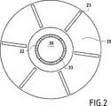
各基材20は隣接する基材から、適当な場合には隣接するプレート11もしくは13またはカバー22から、隙間24を規定する1つまたはそれ以上のスペーサ23で分離される(図1および2を参照のこと)。スペーサ23(例えば放射状に配置される)は、筐体の内部でスタックの外部に位置する外側空間25に内側空間21を連絡させる流路を形成するように配置される。
Each
スペーサ23の間に残る流路は、米国特許第5,904,957号公報に記載されるように、空間21と25との間の圧力をバランスさせるような寸法とする。改変例では、これらは、仏国特許出願第01/03004号に記載されるように、空間21と25との間に圧力勾配が存在し得るように、小さいフローセクションを提供するリーク流路を構成してよい。
The flow path remaining between the
筐体の側面を規定するサセプタ14で筐体を加熱する。一例として、誘導コイル15と誘導結合したインダクタでヒータープレートを構成する。コイル15は筐体を取り囲み、断熱壁16でサセプタ14から分離されている。改変例では、サセプタはこれと熱結合した電気抵抗によって加熱してよい。
The housing is heated by the
炭素の前駆体である1種またはそれ以上の成分を含む反応ガスを筐体の底部17に形成した開口部17aを通じて筐体内に導入する。前駆体はガス状の炭化水素、典型的にはメタン、プロパンまたはそれらの混合物である。底部17とプレート11との間の隙間にて、開口部17aおよび11aを相互接続する円筒壁18により反応ガスを導く。
A reactive gas containing one or more components which are carbon precursors is introduced into the casing through an opening 17a formed in the
垂直管状ダクト30は、開口部11aと接続した下端を有し、空間21の内部にて垂直に基材スタックの頂部の直ぐ近傍にまで延在する。その上端では、ダクト30はカバー31で閉じられている。ダクト30は、モジュール式で構築可能なように、端と端で接続された複数のセクションで構成されていてよい。
The vertical
図1および2に示す態様では、ダクト30は、複数の開口部33をダクト30の長さおよびその軸廻りの双方に沿って配した孔の形態で設けた側壁32を有する。
1 and 2, the
従って、筐体に入った反応ガスはダクト30の開口部33を通過することにより内側空間21へ分配され、基材20を通って拡散し、およびスペーサ23の間に残された流路を通過することにより空間21から空間25へ移る。残りのガスは、筐体のカバー19に形成され、吸引手段(図示せず)に接続された開口部19aを通じて筐体10から取り出される。
Accordingly, the reaction gas entering the casing is distributed to the inner space 21 by passing through the
ダクト30は反応ガスをスタックの高さ全体に亘って分配するように機能するだけでなく、このガスを予備加熱(またはプリヒート)するようにも機能し、ダクト30は筐体内部の温度にまで昇温されている。
The
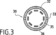
予備加熱を改善するために内側熱交換器壁をダクト30の内部に配置してよい。図3の実施態様では、これらの内側壁は、互いの間に隙間36を残してダクトの軸廻りに配置された長手方向パネル35の形態である。
An inner heat exchanger wall may be placed inside the
ダクト30、カバー31および各内側壁35は、例えばグラファイトで作製される。他の材料、例えばC/C複合材料を用いることもできる。筐体10の壁14、17、19はグラファイトで作製されていることが好都合である。プレート11、13、カバー22、スペーサ23および壁18は、例えばグラファイトで、またはC/C複合材料で作製される。
The
反応ガス入口とスタックを支えるプレート11との間にプレヒーター領域を有する従来の装置と比較して(図4を参照のこと)、図1および2の装置はプレヒーター領域を有さず、このためローディング能力が著しく向上する。プレート11の上方に延在する筐体10のローディング領域は、図4の装置におけるローディング領域よりも大きく、その装置においてプレヒーター領域および互いに重なっている穿孔プレート2は比較的大きな空間を占めている。
Compared to a conventional apparatus having a preheater region between the reaction gas inlet and the
しかしながら、本発明に照らしてプレヒーター領域は存在することも可能であり、該領域は従来の装置のものに比べて小さくできることに留意されるべきである。 However, it should be noted that in the context of the present invention a pre-heater region can be present and that the region can be smaller than that of a conventional device.
ダクト30の直径は、基材20のスタックから離れて配置されるものの、熱交換のために大きな面積を提供し得るのに十分な程度の大きさでなければならない。
The diameter of the
図5および6は、図1および2の装置におけるダクト30の代替となり得る、反応ガスを予備加熱および分配するためのダクト40の改変態様を示す。
FIGS. 5 and 6 show a modification of the
ダクト40の側壁42はダクトの全長に亘って延在する長手方向スロットの形態の開口部43を有し、ダクトはその上端にてカバー41で閉じられている。図示する態様では、スロット43は直線状であり、それらはダクト40の軸廻りに規則的に配置されている。
The
スロット43はダクト40の側壁42を形成する長手方向パネル44の間の隙間によって形成される。熱交換ための追加の内側壁をダクト40の内部に配置する。図3の実施態様におけるように、これらの内側壁はダクトの軸廻りに、互いの間に隙間46を残して配置された長手方向パネル45の形態である。各隙間46が2つのスロット43間のパネル44に面して開口するようにパネル44および45はダクト40の軸廻りにスタガー配置で配置される。
The slots 43 are formed by gaps between the
当然ながら、スロットは直線状流路以外の流路を辿らせることもでき、例えばダクトの底部から頂部までの螺旋状流路を辿らせることもできる。 Of course, the slot can follow a flow path other than the straight flow path, for example, a spiral flow path from the bottom to the top of the duct.
一般的に、ダクトの側壁に形成される開口部を任意の所望形状にすることができ、例えば長方形(または長円形)または軸方向、円周方向もしくは斜方向に延在する細長い開口部にすることができる。 In general, the opening formed in the side wall of the duct can be of any desired shape, for example a rectangular (or oval) or an elongated opening extending in the axial, circumferential or diagonal direction. be able to.
図1および2の実施態様においては基材20の単一のスタックを示す。改変例では、基材の複数のスタックを筐体内部に並置できる。この場合、反応ガスを予備加熱および分配するための個々のダクトを各スタック内部に配置し、反応ガスの共通の入口に、または好ましくはダクトと一直線上にある各自の入口に接続する。
In the embodiment of FIGS. 1 and 2, a single stack of
また、筐体のカバーを通してガス入口を形成し、およびスタックを支持するプレートから離間した底部に出口を形成し、そして、スタックの中央流路をその下端にて閉じて、反応ガスの流れ方向を逆にしてよいことにも留意されるべきである。 In addition, a gas inlet is formed through the cover of the housing, and an outlet is formed at the bottom spaced from the plate supporting the stack. It should also be noted that it may be reversed.
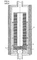
図7に示すように、図1に示すのと同様、誘導コイル115と誘導結合したサセプタ114で側面方向に規定され、それらの間に断熱材116を配置した筐体110内に環状基材120のスタックを受容している。基材120のスタックは、重ね合わされた、および1つまたはそれ以上の中間プレート113によって互いに分離された、また、スタックを閉じるように中央開口部を有さない底部プレート111の上に立っている複数のセクションで構成されている。
As shown in FIG. 7, as shown in FIG. 1, an
その上端では、スタックの内側空間121と軸上配置された中央開口部122aが設けられたカバー122がスタックに載っている。
At the upper end, a
カバー119を通じて筐体110へ入る入口と中央開口部122aとの間にて、入った反応ガスを円筒壁118(これは場合により小さいガスプリヒーター領域で囲われ得る)により導く。
Between the inlet entering the
垂直管状ダクト130は、開口部122aと接続した上端を有し、下向きに、ダクトの下端を閉じるプレート111にまで延在する。ダクト130は上述のダクト30またはダクト40と同様であってよい。図示する態様では、ダクト130は、ダクトの長さに沿って、その軸廻りに配した複数の開口部133を設けた壁132を有する。
The vertical
筐体に入った反応ガスは開口部133を通過することにより基材のスタックの内側空間121へ分配される。このガスは、基材120を通って拡散することにより、および基材間に介挿されたスペーサの間に残された流路を通過することにより空間121から基材スタックの外側の空間125へ移る。残りのガスは筐体の底部117の中央開口部117aを通じて筐体から取り出される。
The reaction gas that has entered the casing passes through the
その他の点については、装置は図1のものと同様である。 In other respects , the apparatus is similar to that of FIG.
本発明の方法および装置はブレーキディスクプリフォーム以外の多孔質基材、例えば図8に示すようなロケットエンジンの末広部用プリフォーム220を構成する基材のための多孔質基材を緻密化するために用いることができる。
The method and apparatus of the present invention densifies a porous substrate other than a brake disk preform, for example, a substrate constituting a
複数の基材220を筐体210の同一のローディング領域に、それらの軸線を垂直上にしながら配置する。底の基材は脚部212aで立っているプレート211で支え、他の基材は環状中間プレート213の上に立たせる。プレート213は支柱またはポスト212bを介して支持プレート211で支持する。
The plurality of
プレート213にある中央開口部213aと共に、基材220の内側空間は基材スタックの内側空間を形成する。空間221はその上端にてカバー222で閉じられている。スペーサ223を基材220の軸端部とプレート211、213との間に介挿し、これにより、基材の外側かつ筐体の内側の空間225に空間221を連絡させるために流路を残すことができる。
Together with the central opening 213a in the
反応ガスを予備加熱および分配するためのダクト230は底部にてプレート211の中央開口部211aに接続されている。ダクト230は空間221の内部にて垂直に基材スタックの頂部の直ぐ近傍にまで延在し、そこではダクト230はカバー231で閉じられている。
The
ダクト230の側壁232は開口部233を、例えば孔の形態で有し、ダクト230は図1および2の態様におけるダクト30と同様のタイプのものである。
The
その他の点については、装置は図1および2の態様と同一である。 In other respects , the apparatus is identical to the embodiment of FIGS.
本願発明の技術分野は、環形状または中空軸対称形状の基材を緻密化することに限定されない。 The technical field of the present invention is not limited to densifying a ring-shaped or hollow axisymmetric substrate.
従って、図9は底部支持プレート311および複数の中間支持プレート313を筐体310のローディング領域に有する筐体310を示す。プレート311および313には、反応ガスを筐体内に入れるための入口と直線上に配置された各中央開口部311aおよび313aが設けられている。
Accordingly, FIG. 9 shows a housing 310 having a
反応ガスを予備加熱および分配するための垂直ダクト330は開口部311aと接続された下端を有し、筐体310のローディング領域を通って垂直に、開口部313aを通過して延在する。ローディング領域の頂部近傍に位置するその上端では、ダクト330はカバー331で閉じられている。
A
プレート311および313は脚部312aおよび支柱312bで支持されている。
The
プレート311、313は、様々な形状および寸法であり得る緻密化用基材320(それら全部は図示せず)を支持する。
The
その他の点については、装置は図1および2に示すものと同一である。
In other respects , the apparatus is identical to that shown in FIGS.
本発明の方法および装置は熱分解炭素のマトリックス以外のマトリックス、例えばセラミックマトリックスで多孔質基材を緻密化するために実施できることに注意されるべきでる。例えば炭化ケイ素(SiC)で出来ているセラミックマトリックスのための化学的蒸気浸透プロセスは周知である。反応ガスの組成は堆積(または蒸着もしくは付着)させるべきマトリックスの性質に応じて選択される。 It should be noted that the method and apparatus of the present invention can be implemented to densify a porous substrate with a matrix other than a matrix of pyrolytic carbon, such as a ceramic matrix. For example, chemical vapor infiltration processes for ceramic matrices made of silicon carbide (SiC) are well known. The composition of the reaction gas is selected depending on the nature of the matrix to be deposited (or evaporated or deposited).
また、ガスを予備加熱および分配するためのダクトの側壁を通過する開口部によって提供されるフローセクションは均一に、あるいはダクトの高さに沿って分配されていてよいことにも注意されるべきである。不均一分配は、管の所定高さにおいて他の高さにおけるよりも反応ガスの必要性が大きい場合に特に適用される。これは、基材のロードの形状(または構造もしくは配置)および/または基材の寸法がローディング領域の高さに沿って変化する場合であり得る。 It should also be noted that the flow section provided by the openings through the duct side walls for preheating and distributing the gas may be distributed uniformly or along the height of the duct. is there. Non-uniform distribution is particularly applicable when the need for reaction gas is greater at a given height of the tube than at other heights. This may be the case when the shape (or structure or arrangement) of the substrate load and / or the dimensions of the substrate vary along the height of the loading area.
Claims (11)
筐体に入った反応ガスは、筐体のローディング領域を通って長手方向に延在するダクトに沿って通すことによって予備加熱され、ダクトは、その第一長手方向端において、筐体の第一長手方向端近傍に位置する入口を通じて開口し、その第一長手方向端と反対側の第二長手方向端において閉じており、およびその側壁に全長に亘って形成された複数の側方開口部が設けられており、および、ダクトの入口は壁を介して筐体の入口に密封的に接続されており、筐体に入った全ての反応ガスが、ダクトの入口を通ってダクトの内部に導かれることにより予備加熱され、そして、予備加熱されたガスは、ダクトの側方開口部のみを通ってダクトから出ることによりローディング領域に沿って分配されることを特徴とする方法。A method for densifying a porous base material by chemical vapor infiltration, wherein the porous base material for densification is loaded into a loading region of the casing, the inner space of the casing is heated, and the casing Reactive gas is introduced into the housing through an inlet located at the first longitudinal end of the first, and residual gas is extracted from the housing through an outlet located at the second longitudinal end opposite to the first longitudinal end of the housing; And pre-heating the reaction gas after it has entered the housing and before it comes into contact with the substrate located in the loading area of the housing,
The reaction gas entering the enclosure is preheated by passing along a duct extending longitudinally through the loading area of the enclosure, the duct being at its first longitudinal end at the first longitudinal end of the enclosure. Opened through an inlet located near the longitudinal end, closed at the second longitudinal end opposite the first longitudinal end, and a plurality of side openings formed over the entire length of the side wall provided, and an inlet duct is sealingly connected to the inlet of the housing through the wall, all the reaction gas entering the housing, guiding the interior of the duct through the inlet duct A method characterized in that it is preheated by being and the preheated gas is distributed along the loading area by exiting the duct only through the side openings of the duct.
予備加熱手段は、筐体のローディング領域を通って長手方向に延在するダクトの形態を有し、ダクトはその第一長手方向端において、筐体の第一長手方向端近傍に位置する入口を通じて開口し、および壁を介して筐体の入口に密封的に接続されており、ダクトはその第一長手方向端と反対側の第二長手方向端において閉じており、およびダクトは、その側壁に全長に亘って形成された複数の側方開口部が設けられていることを特徴とする装置。An apparatus for densifying a porous substrate by chemical vapor infiltration, a casing, a loading region for loading a substrate to be densified in the casing, and means for heating an inner space of the casing The reaction gas inlet at the first longitudinal end of the housing, the residual gas outlet at the second longitudinal end opposite to the first longitudinal end of the housing, Means located within the housing for heating,
The preheating means has the form of a duct extending longitudinally through the loading area of the housing, the duct being at its first longitudinal end through an inlet located near the first longitudinal end of the housing. open, and are sealingly connected to the inlet of the housing through the wall, the duct is closed in a second longitudinal end opposite to its first longitudinal end, and the duct has, in its side walls A device comprising a plurality of side openings formed over the entire length.
Applications Claiming Priority (2)
| Application Number | Priority Date | Filing Date | Title |
|---|---|---|---|
| FR0200412A FR2834713B1 (en) | 2002-01-15 | 2002-01-15 | PROCESS AND PLANT FOR DENSIFICATION OF SUBSTRATES BY CHEMICAL STEAM INFILTRATION |
| PCT/FR2003/000097 WO2003060183A1 (en) | 2002-01-15 | 2003-01-14 | Method and installation for the densification of substrates by means of chemical vapour infiltration |
Publications (3)
| Publication Number | Publication Date |
|---|---|
| JP2005514524A JP2005514524A (en) | 2005-05-19 |
| JP2005514524A5 JP2005514524A5 (en) | 2006-01-05 |
| JP4495970B2 true JP4495970B2 (en) | 2010-07-07 |
Family
ID=8871284
Family Applications (1)
| Application Number | Title | Priority Date | Filing Date |
|---|---|---|---|
| JP2003560261A Expired - Lifetime JP4495970B2 (en) | 2002-01-15 | 2003-01-14 | Method and apparatus for densification of substrate by chemical vapor infiltration |
Country Status (13)
| Country | Link |
|---|---|
| US (1) | US7691440B2 (en) |
| EP (1) | EP1466031B1 (en) |
| JP (1) | JP4495970B2 (en) |
| KR (1) | KR100985377B1 (en) |
| CN (1) | CN1244714C (en) |
| AT (1) | ATE488616T1 (en) |
| AU (1) | AU2003216719A1 (en) |
| CA (1) | CA2445501A1 (en) |
| DE (1) | DE60334970D1 (en) |
| FR (1) | FR2834713B1 (en) |
| RU (1) | RU2293795C2 (en) |
| UA (1) | UA76987C2 (en) |
| WO (1) | WO2003060183A1 (en) |
Families Citing this family (26)
| Publication number | Priority date | Publication date | Assignee | Title |
|---|---|---|---|---|
| FR2881145B1 (en) * | 2005-01-24 | 2007-11-23 | Snecma Propulsion Solide Sa | METHOD OF GAS PHASE CHEMICAL INFILTRATION FOR THE DENSIFICATION OF POROUS SUBSTRATES WITH PYROLYTIC CARBON |
| FR2882064B1 (en) * | 2005-02-17 | 2007-05-11 | Snecma Propulsion Solide Sa | PROCESS FOR THE DENSIFICATION OF THIN POROUS SUBSTRATES BY CHEMICAL VAPOR PHASE INFILTRATION AND DEVICE FOR LOADING SUCH SUBSTRATES |
| CN1304912C (en) * | 2005-02-21 | 2007-03-14 | 西北工业大学 | Carbon / carbon composite material heat gradient chemical gaseous phase permeation process temperature automatic controller |
| CN101671189B (en) * | 2009-09-23 | 2012-07-18 | 北京航空航天大学 | Method for using domestic carbon fiber to prepare high-performance carbon-based composite material through rapid directional infiltration |
| CN102953049B (en) * | 2011-08-25 | 2015-07-08 | 沈阳金研机床工具有限公司 | Device for chemical vapor deposition coating |
| FR2980486B1 (en) | 2011-09-28 | 2013-10-11 | Snecma Propulsion Solide | LOADING DEVICE FOR DENSIFICATION BY DIRECT FLOW STEAM CHEMICAL INFILTRATION OF THREE-DIMENSIONAL POROUS SUBSTRATES |
| FR2993044B1 (en) * | 2012-07-04 | 2014-08-08 | Herakles | LOADING DEVICE AND INSTALLATION FOR THE DENSIFICATION OF POROUS, TRUNCONIC AND STACKABLE PREFORMS |
| FR2993555B1 (en) | 2012-07-19 | 2015-02-20 | Herakles | INSTALLATION OF HEAVY DUTY CHEMICAL INFILTRATION WITH HIGH LOAD CAPACITY |
| CN102964144B (en) * | 2012-11-19 | 2014-04-02 | 西北工业大学 | Method for improving oxidation resistance of surface coating layer of carbon/carbon composite material |
| FR3004732B1 (en) * | 2013-04-18 | 2015-05-08 | Herakles | TOOLS FOR MAINTENANCE, LOADING AND INSTALLATION FOR THE DENSIFICATION OF POROUS REVOLUTION PREFORMS |
| KR101589965B1 (en) * | 2014-02-26 | 2016-02-05 | (주) 데크카본 | Apparatus for densifying c/c composite material |
| FR3018526B1 (en) * | 2014-03-14 | 2021-06-11 | Herakles | CVI DENSIFICATION INSTALLATION INCLUDING A HIGH-CAPACITY PREHEATING ZONE |
| US9834842B2 (en) | 2015-05-15 | 2017-12-05 | Goodrich Corporation | Slotted seal plates and slotted preforms for chemical vapor deposition densification |
| WO2017033053A1 (en) | 2015-08-21 | 2017-03-02 | Flisom Ag | Homogeneous linear evaporation source |
| TWI624554B (en) * | 2015-08-21 | 2018-05-21 | 弗里松股份有限公司 | Evaporation source |
| US10407769B2 (en) * | 2016-03-18 | 2019-09-10 | Goodrich Corporation | Method and apparatus for decreasing the radial temperature gradient in CVI/CVD furnaces |
| CN108088247B (en) * | 2017-12-28 | 2019-08-13 | 德淮半导体有限公司 | Furnace tube apparatus |
| US10731252B2 (en) * | 2018-05-25 | 2020-08-04 | Rolls-Royce High Temperature Composites | Apparatus and method for coating specimens |
| FR3083229B1 (en) | 2018-06-27 | 2020-09-11 | Safran Ceram | PROCESS FOR DENSIFICATION BY CHEMICAL INFILTRATION IN THE GASEOUS PHASE OF POROUS ANNULAR SUBSTRATES |
| FR3084672B1 (en) * | 2018-08-03 | 2020-10-16 | Safran Ceram | PROCESS FOR DENSIFICATION BY CHEMICAL INFILTRATION IN GAS PHASE OF ANNULAR POROUS SUBSTRATES |
| FR3084892B1 (en) | 2018-08-10 | 2020-11-06 | Safran Ceram | PROCESS FOR DENSIFICATION BY CHEMICAL INFILTRATION IN THE GASEOUS PHASE OF POROUS ANNULAR SUBSTRATES |
| FR3095213B1 (en) * | 2019-04-19 | 2022-12-23 | Safran Ceram | CVI densification plant |
| FR3129954B1 (en) * | 2021-12-06 | 2023-12-15 | Safran Ceram | Double reaction chamber gas phase chemical infiltration plant |
| US11932941B1 (en) | 2021-12-29 | 2024-03-19 | Rolls-Royce High Temperature Composites, Inc. | Load assemblies for loading parts in a furnace |
| FR3132718A1 (en) | 2022-02-16 | 2023-08-18 | Safran Landing Systems | Gas phase chemical infiltration densification process with monopile trays for semi-forced flow |
| FR3132717B1 (en) | 2022-02-16 | 2024-02-16 | Safran Landing Systems | Multi-pile tray tooling for semi-forced flow |
Family Cites Families (11)
| Publication number | Priority date | Publication date | Assignee | Title |
|---|---|---|---|---|
| US2729190A (en) * | 1951-10-08 | 1956-01-03 | Pawlyk Peter | Apparatus for plating the interior of hollow objects |
| US4580524A (en) * | 1984-09-07 | 1986-04-08 | The United States Of America As Represented By The United States Department Of Energy | Process for the preparation of fiber-reinforced ceramic composites by chemical vapor deposition |
| JP2839621B2 (en) * | 1990-02-13 | 1998-12-16 | 株式会社東芝 | Thermal diffusion equipment for semiconductor manufacturing |
| US6022414A (en) * | 1994-07-18 | 2000-02-08 | Semiconductor Equipment Group, Llc | Single body injector and method for delivering gases to a surface |
| US5480678A (en) | 1994-11-16 | 1996-01-02 | The B. F. Goodrich Company | Apparatus for use with CVI/CVD processes |
| DE69526259T2 (en) * | 1994-11-16 | 2002-11-07 | Goodrich Co B F | CVD / CVI pressure field device, method and product |
| FR2733254B1 (en) * | 1995-04-18 | 1997-07-18 | Europ Propulsion | CHEMICAL VAPOR INFILTRATION PROCESS FOR THE DENSIFICATION OF POROUS SUBSTRATES DISPOSED IN RING STACKS |
| FR2754813B1 (en) * | 1996-10-18 | 1999-01-15 | Europ Propulsion | DENSIFICATION OF POROUS SUBSTRATES DISPOSED IN ANNULAR CELLS BY CHEMICAL VAPOR INFILTRATION WITH TEMPERATURE GRADIENT |
| KR100360401B1 (en) * | 2000-03-17 | 2002-11-13 | 삼성전자 주식회사 | Process tube having a slit type process gas injection portion and a waste gas exhaust portion of multi hole type and apparatus for semiconductor fabricating |
| FR2818291B1 (en) * | 2000-12-19 | 2003-11-07 | Snecma Moteurs | DENSIFICATION OF HOLLOW POROUS SUBSTRATES BY CHEMICAL STEAM INFILTRATION |
| US6953605B2 (en) * | 2001-12-26 | 2005-10-11 | Messier-Bugatti | Method for densifying porous substrates by chemical vapour infiltration with preheated gas |
-
2002
- 2002-01-15 FR FR0200412A patent/FR2834713B1/en not_active Expired - Fee Related
-
2003
- 2003-01-14 CN CNB038002973A patent/CN1244714C/en not_active Expired - Fee Related
- 2003-01-14 AU AU2003216719A patent/AU2003216719A1/en not_active Abandoned
- 2003-01-14 CA CA002445501A patent/CA2445501A1/en not_active Abandoned
- 2003-01-14 WO PCT/FR2003/000097 patent/WO2003060183A1/en active Application Filing
- 2003-01-14 RU RU2003131510/02A patent/RU2293795C2/en not_active IP Right Cessation
- 2003-01-14 KR KR1020037014158A patent/KR100985377B1/en active IP Right Grant
- 2003-01-14 AT AT03712238T patent/ATE488616T1/en active
- 2003-01-14 EP EP03712238A patent/EP1466031B1/en not_active Expired - Lifetime
- 2003-01-14 DE DE60334970T patent/DE60334970D1/en not_active Expired - Lifetime
- 2003-01-14 JP JP2003560261A patent/JP4495970B2/en not_active Expired - Lifetime
- 2003-01-14 UA UA20031211542A patent/UA76987C2/en unknown
- 2003-01-14 US US10/475,464 patent/US7691440B2/en not_active Expired - Fee Related
Also Published As
| Publication number | Publication date |
|---|---|
| KR20040095145A (en) | 2004-11-12 |
| CN1511198A (en) | 2004-07-07 |
| ATE488616T1 (en) | 2010-12-15 |
| CN1244714C (en) | 2006-03-08 |
| FR2834713A1 (en) | 2003-07-18 |
| UA76987C2 (en) | 2006-10-16 |
| JP2005514524A (en) | 2005-05-19 |
| AU2003216719A1 (en) | 2003-07-30 |
| DE60334970D1 (en) | 2010-12-30 |
| KR100985377B1 (en) | 2010-10-04 |
| FR2834713B1 (en) | 2004-04-02 |
| US20040237898A1 (en) | 2004-12-02 |
| WO2003060183A1 (en) | 2003-07-24 |
| EP1466031B1 (en) | 2010-11-17 |
| RU2003131510A (en) | 2005-04-20 |
| CA2445501A1 (en) | 2003-07-24 |
| US7691440B2 (en) | 2010-04-06 |
| RU2293795C2 (en) | 2007-02-20 |
| EP1466031A1 (en) | 2004-10-13 |
Similar Documents
| Publication | Publication Date | Title |
|---|---|---|
| JP4495970B2 (en) | Method and apparatus for densification of substrate by chemical vapor infiltration | |
| US6572371B1 (en) | Gas preheater and process for controlling distribution of preheated reactive gas in a CVI furnace for densification of porous annular substrates | |
| JP4426302B2 (en) | Method and apparatus for densifying porous substrates by chemical vapor infiltration | |
| JP4960264B2 (en) | Method for densifying thin porous substrate by chemical vapor infiltration and loading device for the substrate | |
| US5904957A (en) | Vapour phase chemical infiltration process for densifying porous substrates disposed in annular stacks | |
| US9845534B2 (en) | CVI densification installation including a high capacity preheating zone | |
| US7182980B2 (en) | Chemical vapor infiltration method for densifying porous substrates having a central passage | |
| JP6155438B2 (en) | Loading device and equipment for densification of stackable frustoconical porous preforms | |
| US11512024B2 (en) | Method for densifying porous annular substrates by chemical vapour infiltration | |
| JP2015502451A (en) | Apparatus for loading a three-dimensionally shaped porous substrate for densification by chemical vapor infiltration in a directional flow |
Legal Events
| Date | Code | Title | Description |
|---|---|---|---|
| A621 | Written request for application examination |
Free format text: JAPANESE INTERMEDIATE CODE: A621 Effective date: 20050826 |
|
| A521 | Request for written amendment filed |
Free format text: JAPANESE INTERMEDIATE CODE: A523 Effective date: 20050909 |
|
| A131 | Notification of reasons for refusal |
Free format text: JAPANESE INTERMEDIATE CODE: A131 Effective date: 20080812 |
|
| A601 | Written request for extension of time |
Free format text: JAPANESE INTERMEDIATE CODE: A601 Effective date: 20081105 |
|
| A602 | Written permission of extension of time |
Free format text: JAPANESE INTERMEDIATE CODE: A602 Effective date: 20081112 |
|
| A601 | Written request for extension of time |
Free format text: JAPANESE INTERMEDIATE CODE: A601 Effective date: 20081204 |
|
| A602 | Written permission of extension of time |
Free format text: JAPANESE INTERMEDIATE CODE: A602 Effective date: 20081211 |
|
| A521 | Request for written amendment filed |
Free format text: JAPANESE INTERMEDIATE CODE: A523 Effective date: 20090109 |
|
| A131 | Notification of reasons for refusal |
Free format text: JAPANESE INTERMEDIATE CODE: A131 Effective date: 20090825 |
|
| A521 | Request for written amendment filed |
Free format text: JAPANESE INTERMEDIATE CODE: A523 Effective date: 20091117 |
|
| TRDD | Decision of grant or rejection written | ||
| A01 | Written decision to grant a patent or to grant a registration (utility model) |
Free format text: JAPANESE INTERMEDIATE CODE: A01 Effective date: 20100316 |
|
| A01 | Written decision to grant a patent or to grant a registration (utility model) |
Free format text: JAPANESE INTERMEDIATE CODE: A01 |
|
| A61 | First payment of annual fees (during grant procedure) |
Free format text: JAPANESE INTERMEDIATE CODE: A61 Effective date: 20100412 |
|
| R150 | Certificate of patent or registration of utility model |
Ref document number: 4495970 Country of ref document: JP Free format text: JAPANESE INTERMEDIATE CODE: R150 Free format text: JAPANESE INTERMEDIATE CODE: R150 |
|
| FPAY | Renewal fee payment (event date is renewal date of database) |
Free format text: PAYMENT UNTIL: 20130416 Year of fee payment: 3 |
|
| FPAY | Renewal fee payment (event date is renewal date of database) |
Free format text: PAYMENT UNTIL: 20140416 Year of fee payment: 4 |
|
| R250 | Receipt of annual fees |
Free format text: JAPANESE INTERMEDIATE CODE: R250 |
|
| S111 | Request for change of ownership or part of ownership |
Free format text: JAPANESE INTERMEDIATE CODE: R313111 |
|
| R360 | Written notification for declining of transfer of rights |
Free format text: JAPANESE INTERMEDIATE CODE: R360 |
|
| R360 | Written notification for declining of transfer of rights |
Free format text: JAPANESE INTERMEDIATE CODE: R360 |
|
| R371 | Transfer withdrawn |
Free format text: JAPANESE INTERMEDIATE CODE: R371 |
|
| S111 | Request for change of ownership or part of ownership |
Free format text: JAPANESE INTERMEDIATE CODE: R313111 |
|
| R350 | Written notification of registration of transfer |
Free format text: JAPANESE INTERMEDIATE CODE: R350 |
|
| R250 | Receipt of annual fees |
Free format text: JAPANESE INTERMEDIATE CODE: R250 |
|
| R250 | Receipt of annual fees |
Free format text: JAPANESE INTERMEDIATE CODE: R250 |
|
| R250 | Receipt of annual fees |
Free format text: JAPANESE INTERMEDIATE CODE: R250 |
|
| R250 | Receipt of annual fees |
Free format text: JAPANESE INTERMEDIATE CODE: R250 |
|
| R250 | Receipt of annual fees |
Free format text: JAPANESE INTERMEDIATE CODE: R250 |
|
| R250 | Receipt of annual fees |
Free format text: JAPANESE INTERMEDIATE CODE: R250 |
|
| R250 | Receipt of annual fees |
Free format text: JAPANESE INTERMEDIATE CODE: R250 |