JP4491908B2 - Conductive polycarbonate molding - Google Patents
Conductive polycarbonate molding Download PDFInfo
- Publication number
- JP4491908B2 JP4491908B2 JP2000126110A JP2000126110A JP4491908B2 JP 4491908 B2 JP4491908 B2 JP 4491908B2 JP 2000126110 A JP2000126110 A JP 2000126110A JP 2000126110 A JP2000126110 A JP 2000126110A JP 4491908 B2 JP4491908 B2 JP 4491908B2
- Authority
- JP
- Japan
- Prior art keywords
- polycarbonate resin
- raw material
- polycarbonate
- molding
- molded body
- Prior art date
- Legal status (The legal status is an assumption and is not a legal conclusion. Google has not performed a legal analysis and makes no representation as to the accuracy of the status listed.)
- Expired - Lifetime
Links
Images
Landscapes
- Packaging Frangible Articles (AREA)
- Manufacture Of Macromolecular Shaped Articles (AREA)
- Injection Moulding Of Plastics Or The Like (AREA)
- Compositions Of Macromolecular Compounds (AREA)
Description
【0001】
【発明の属する技術分野】
本発明は、導電性ポリカーボネート成形体に関するものであり、詳しくは、電気電子分野や自動車分野における帯電防止部品として、例えば半導体デバイスの製造、搬送工程におけるトレイやケース、パッケージなどの包装部材、とりわけハードディスクドライブ用のディスクや、磁気ヘッド用の静電防止部材として好適な導電性ポリカーボネート成形体に関する。
【0002】
【従来の技術】
近年、半導体デバイスの情報記録の高密度化、処理速度の高速化に伴い、半導体デバイスは静電気に対して極めて弱くなってきていることから、これを収納するケースや取り扱い治工具などの静電気防止対策が重要となってきている。
【0003】
従来、この静電気防止対策としては、例えばABS、ポリカーボネート、変性ポリフェニレンエーテル(PPE)などの熱可塑性樹脂に、帯電防止剤、カーボンブラック、カーボンファイバー等の導電性付与成分を配合分散させる方法が施されている。
【0004】
しかしながら、これらの方法では、それぞれ以下の問題点がある。即ち、帯電防止剤の場合には、導電機構がイオン伝導であることに起因して、環境湿度の影響を受け易く、また、洗浄や長時間の使用により帯電防止剤が流出し、帯電防止性が低下する;大量に添加すると耐熱性を損なう;などの問題点がある。また、カーボンブラックやカーボンファイバーは湿度、洗浄等の影響は受けないものの、成形体からカーボン粒子やカーボンファイバーが脱落しやすく、デバイスを損傷するなどの問題が生じている。
【0005】
これに対して、導電性付与成分として平均繊維径200nm以下の炭素フィブリルを配合した場合には、成形体からの脱落が少ないため、脱落による問題は軽減されることから、導電性付与成分としてこのような炭素フィブリルを用いることが、静電気防止対策として有効であると考えられている。
【0006】
【発明が解決しようとする課題】
しかしながら、炭素フィブリルでは、炭素フィブリルを添加することにより、機械的強度、特に衝撃強度が著しく損なわれ、成形体の落下時等にクラックを生じやすい;導電性付与のためには、比較的多くの配合量を必要とするが、炭素フィブリルは極めて高価であるため、この場合には、製品のコストアップにつながる;炭素フィブリルの添加量を少なくすると、得られる成形体の導電性が著しく損なわれる;といった欠点がある。
【0007】
本発明は上記従来の問題点を解決し、少ない炭素フィブリル配合量で高い導電性を発現することができ、従って、安価で衝撃強度等の機械的強度に優れた導電性ポリカーボネート成形体を提供することを目的とする。
【0008】
【課題を解決するための手段】
本発明の導電性ポリカーボネート成形体は、ポリカーボネート樹脂に、平均繊維径200nm以下の炭素フィブリルを0.1〜40重量%配合した組成物を成形してなる導電性ポリカーボネート成形体であって、成形体を構成するポリカーボネート樹脂の重量平均分子量が30,000〜45,000であることを特徴とする。
【0009】
一般的なポリカーボネート樹脂の重量平均分子量(Mw)は、例えば射出成形用途としては50,000〜60,000程度であり、このようなMwのポリカーボネート樹脂を用いた組成物を成形して得られる成形体を構成するポリカーボネート樹脂のMwは45,000〜55,000程度である。即ち、成形による樹脂の劣化で、成形前に比べて成形後の成形体中に含まれるポリカーボネート樹脂のMwは低下する。
【0010】
本発明者らは炭素フィブリルによる導電性の発現効果について鋭意検討した結果、ポリカーボネート樹脂に、直径200nm以下の炭素フィブリルを0.1〜40重量%を配合した組成物を成形してなる成形体で、成形体を構成するポリカーボネート樹脂のMwが30,000〜45,000と、通常のポリカーボネート樹脂成形体中のポリカーボネート樹脂のMwよりも小さい成形体は、導電性の発現が著しく良好となり、少ない炭素フィブリル配合量で、従って、コストの向上や機械的強度の低下を引き起こすことなく、優れた導電性を得ることができることを見出し、本発明を完成させた。
【0011】
本発明の範囲内のポリカーボネート樹脂を採用することによる導電性の向上効果の作用機構の詳細は明らかではないが、次のように推定される。
【0012】
即ち、成形時の樹脂の流動に伴い、特に成形体表面付近では強い剪断応力を受けて、炭素フィブリルの分散形態が流動方向に変形したり、炭素フィブリル自体が破断したりすると考えられるが、ベース樹脂であるポリカーボネート樹脂の分子量が本発明の範囲内であると、炭素フィブリルの分散形態の破壊が少なく、結果として、成形体中の炭素フィブリルが、導電性ネットワークとして効率良く機能するものと思われる。
【0013】
特に、この成形原料として、下記原料Aと原料Bとの混合物を用いることにより、導電性が更に改良され、しかも衝撃強度とのバランスも良好な導電性ポリカーボネート成形体を得ることができる。
【0014】
原料A:得られる成形体の炭素フィブリル含有量に対して0.9〜1.1倍の割合で平均繊維径200nmの炭素フィブリルを含むポリカーボネート樹脂組成物の粒状体
原料B:原料Aのポリカーボネート樹脂よりもMwが5%以上大きいポリカーボネート樹脂及び平均繊維径200nm以下の炭素フィブリル
このようにポリカーボネート樹脂のMwが5%以上異なる組成物を混合して成形することで、導電性が向上する理由は明らかではないが、高分子量成分である原料Bにおいて高粘度下で混練されたことにより、炭素フィブリルの分散が良好となり、一方で、低分子量成分である原料Aの存在によって、前述の炭素フィブリルの分散形態の破壊が防止されることによる相乗効果であるとも考えられる。
【0015】
本発明の導電性ポリカーボネート成形体は、特に、射出成形により成形されることが好ましい。
【0016】
【発明の実施の形態】
以下に本発明の導電性ポリカーボネート成形体の実施の形態を詳細に説明する。
【0017】
本発明において、ポリカーボネート樹脂としては、例えば界面重合法、ピリジン法、クロロホーメート法などの溶液法により、二価フェノール系化合物をホスゲンと反応させることによって製造される一般的なものを使用でき、このようなポリカーボネート樹脂は市販品を使用することができる。
【0018】
本発明で使用される炭素フィブリルは、平均繊維径(直径)200nm以下の炭素フィブリルであり、例えば特表平8−508534号公報に記載されているものが使用できる。
【0019】
炭素フィブリルは、当該フィブリルの円柱状軸に実質的に同心的に沿って沈着されているグラファイト外層を有し、その繊維中心軸は直線状でなく、うねうねと曲がりくねった管状の形態を有する。この炭素フィブリルの平均繊維径は製法に依存し、ほぼ均一なものである。
【0020】
炭素フィブリルの平均繊維径が200nmより大きいと、樹脂中でのフィブリル同士の接触が不十分となり、安定した抵抗値が得られ難い。従って、炭素フィブリルとしては平均繊維径200nm以下のものを用いる。特に炭素フィブリルの平均繊維径が20nm以下であると、得られる成形体の抵抗値が均一になるので望ましい。ただし、炭素フィブリルの平均繊維径が過度に小さいと、製造が著しく困難となるため、炭素フィブリルの平均繊維径は0.1nm以上、特に0.5nm以上であることが望ましい。
【0021】
また、炭素フィブリルは、長さと平均繊維径との比(長さ/径)が5以上のものが好ましく、特に100以上、とりわけ1000以上の長さ/径比を有するものが望ましい。
【0022】
また、微細な管状の形態を有するフィブリルの壁(管状体の壁厚)厚みは、通常3.5〜75nm程度である。これは、通常フィブリルの外径の約0.1〜0.4倍に該当する。
【0023】
なお、この炭素フィブリルの平均繊維径、平均繊維長(及びアスペクト比)は、透過型電子顕微鏡での観察において、5点の実測値の平均値によって得られる。
【0024】
このような炭素フィブリルは、市販のものを使用することができ、例えば、ハイペリオンカタリシスインターナショナル社の「BN」が使用できる。
【0025】
炭素フィブリルの配合量は樹脂組成物中に0.1〜40重量%好ましくは0.5〜10重量%、より好ましくは1〜5重量%である。炭素フィブリルの配合量がこの範囲よりも少ないと導電性が十分に発現せず、この範囲より多いと成形性が著しく低下したり、成形体強度が低下したりする。
【0026】
なお、炭素フィブリルはその少なくとも一部分が凝集体の形態である場合、原料となる樹脂組成物中に、面積ベースで測定して約50μm、特に10μmよりも大きい径を有するフィブリル凝集体を含有していないことが望ましい。
【0027】
本発明に係るポリカーボネート樹脂組成物には必要に応じて、その性能を損なわない範囲で付加成分を配合することができる。このような付加成分としては、例えば、ガラス繊維、シリカ繊維、シリカ・アルミナ繊維、チタン酸カリウム繊維、硼酸アルミニウム繊維等の無機繊維状強化材、アラミド繊維、ポリイミド繊維、フッ素樹脂繊維等の有機繊維状強化材、タルク、炭酸カルシウム、マイカ、ガラスビーズ、ガラスパウダー、ガラスバルーン等の無機充填剤、フッ素樹脂パウダー、二硫化モリブデン等の固体潤滑剤、パラフィンオイル等の可塑剤、酸化防止剤、熱安定剤、光安定剤、紫外線吸収剤、中和剤、滑剤、相溶化剤、防曇剤、アンチブロッキング剤、スリップ剤、分散剤、着色剤、防菌剤、蛍光増白剤等といった各種添加剤を挙げることができる。
【0028】
本発明の導電性ポリカーボネート成形体は、通常の熱可塑性樹脂の加工方法で製造することができ、例えば、ポリカーボネート樹脂に炭素フィブリル、必要に応じて添加されるその他の付加成分を予め混合した後、バンバリーミキサー、ロール、ブラベンダー、単軸混練押し出し機、二軸混練押し出し機、ニーダーなどで溶融混練することによってポリカーボネート樹脂組成物を製造し、その後、この樹脂組成物を各種の溶融成形法で成形することにより製造することができる。成形法としては、具体的にはプレス成形、押し出し成形、真空成形、ブロー成形、射出成形などを挙げることができるが、これらの成形方法の中でも特に射出成形が望ましい。
【0029】
射出成形方法としては、一般的な射出成形法の他に、インサート射出成形法による金属部品、その他の部品との一体成形や、二色射出成形法、コアバック射出成形法、サンドイッチ射出成形法、インジェクションプレス成形法等の各種成形法を用いることができる。射出成形においては、樹脂温度、金型温度、成形圧力によって製品の表面抵抗値が変化するので、適切な条件を設定する必要がある。
【0030】
特に、本発明においては、射出成形によるポリカーボネート樹脂のMwの低下が2%以上、望ましくは2〜5%になるように成形条件を設定すると、得られる成形体の導電性が良好となる点で望ましい。
【0031】
また、射出成形法における金型のキャビティより樹脂組成物を注入する際のゲート(注入口)としては、サイドゲート、フィルムゲート、サブマリンゲート、ピンゲート等を使用することができる。これらのゲートの断面積としては、0.2mm2以上が望ましい。
【0032】
中でも成形後にゲート処理が不要なピンゲートが生産性の点で望ましいが、その場合には、ピンゲートの直径が0.5〜3mm、特に1.0〜2.5mmであることが望ましい。ピンゲートのゲート直径は、樹脂が金型内に十分に充填できる範囲内であれば、小さい方が望ましく、一般的に0.2〜0.5mmである。しかしながら、本発明では、ゲート径(断面積)が小さいと、ゲート部分を樹脂組成物が流れる際に、過度の剪断を受けるため、炭素フィブリルによる導電性ネットワークの破壊が起こりやすい。一方、ゲート径が大き過ぎると、成形体のゲート部の切れが悪化して仕上がりが悪くなる。このため、ゲート直径は上記範囲とするのが好ましい。
【0033】
また、本発明の成形体の成形に際しては、樹脂組成物の流動性が良好であるために、金型の転写性が良好である。上述のようにゲートが比較的大きいと更に転写しやすくなる。かかる成形体の金型においては、パーティング面に対して80〜100度(垂直に近い)の角度を有する平面部位の表面が滑らかであることが望ましい。
【0034】
即ち、パーティング面に垂直に近い面の表面粗さが粗いと、樹脂がこれを転写し、金型から製品を取出す際に必要な力が大きくなり、成形体の破損などの不具合が生じる。従って、例えば、このパーティング面に対して垂直に近い面の表面粗さが、カットオフ波長2.5mmの測定における10点平均粗さ(Rz)において、10μm以下、望ましくは5μm以下、とりわけ望ましくは3μm以下であることが好ましい。
【0035】
また、上記流動性を得るために、本発明の成形体を構成するポリカーボネート樹脂組成物のメルトフローレート(MFR)は、280℃、2.16kg荷重の測定において、2〜30g/10分、特に4〜15g/10分であることが望ましい。
【0036】
なお、本発明の導電性ポリカーボネート成形体を半導体デバイスの周辺部品として使用する場合、特にポリカーボネート成形体からのガスの発生量が少ないことが望ましく、具体的にはヘッドスペースガスクロマトグラムによる測定における、加熱温度85℃、平衡時間16時間の条件で測定した表面積12.8cm2からの塩素化炭化水素発生量が0.1μg/g以下、総アウトガス量が1μg/g以下であることが望ましい。従って、このような成形体を得るために、樹脂組成物の製造時に揮発成分を脱気するか、重合溶媒を使用しない製造方法で重合されたポリカーボネート樹脂を使用することが望ましい。
【0037】
本発明の導電性ポリカーボネート成形体は、成形体中のポリカーボネート樹脂のMwが30,000〜45,000、好ましくは、35,000〜43,000であることに特徴を有する。このMwが上記範囲より大きいと、成形体の導電性が損なわれ、表面抵抗値が高くなり、上記範囲より小さいと、衝撃強度が極端に低下したり、成形体にクラックを生じるなどの問題が生じる。
【0038】
このようなMw範囲内のポリカーボネート樹脂成形体を得る方法としては、例えば、予め本発明の範囲内、又はこれより大きめの分子量を有するポリカーボネート樹脂を用いて成形体を製造し、製造時の加工温度条件等を調整したり、成形を繰り返し行うなどによってポリカーボネート樹脂の分子量を適度に低下させる方法が挙げられるが、特に、下記原料Aと原料Bとの混合物を溶融成形する方法が、容易に望ましい分子量に調整できるだけでなく、得られる成形体の導電性と衝撃強度のバランスがさらに良好となることから好ましい。
【0039】
原料A:得られる成形体の炭素フィブリル含有量に対して0.9〜1.1倍の割合で平均繊維径200nmの炭素フィブリルを含むポリカーボネート樹脂組成物の粒状体
原料B:原料Aのポリカーボネート樹脂よりもMwが5%以上大きいポリカーボネート樹脂及び平均繊維径200nm以下の炭素フィブリル
この場合、原料BのMwが原料Aのポリカーボネート樹脂のMwの分子量よりも5%以上大きくない場合には、衝撃強度及び導電性改良効果が少ない。この分子量が過度に大きいと、Mwの調整が困難となることから、原料Bのポリカーボネート樹脂のMwは、原料Aのポリカーボネート樹脂のMwより5〜300%(3倍)大きい程度とするのが望ましい。
【0040】
原料Aと原料Bの混合物中の原料Aの比率は5〜95重量%、特に10〜70重量%であると、特に導電性改良効果が大きいので望ましい。また、原料Aのポリカーボネート樹脂のMwは20,000〜45,000、特に30,000〜43,000であることが望ましい。
【0041】
原料Aと原料Bとの混合方法は、原料Bを溶融混練する際に、原料Aを混練押出機に投入して混合しても良いし、予め原料Bを溶融混練して得られたペレットを、原料Aと混合した後に成形しても良い。
【0042】
なお、原料Aとしては、半導体製造工程等で用いられている導電性ポリカーボネート成形体製トレイやケース等の廃品を粉砕して用いることもでき、この場合には、廃棄物の有効再利用で廃棄物の減量化と原料のコストダウンを図ることができる。
【0043】
【実施例】
以下に実施例及び比較例を挙げて本発明をより具体的に説明する。
【0044】
なお、以下において、ポリカーボネート樹脂は、三菱エンジニアリングプラスチック社製「ユーピロン」を使用した。
【0045】
また、炭素フィブリルは、ハイペリオンカタリシスインターナショナル社製「BN」タイプを使用した。なお炭素フィブリルはポリカーボネート樹脂に予め15重量%の添加量で分散させたマスターバッチを使用した。また、樹脂組成物中に分散した炭素フィブリルは、平均繊維径10nm、平均繊維長1μm以上である。なお、実施例及び比較例で用いたポリカーボネート樹脂1〜6の混練配合、成形及び各種物性ないし特性の測定方法は下記の通りである。
【0046】
(1)ポリカーボネート樹脂組成物の混練配合
[ポリカーボネート樹脂組成物1,2,3,5,7]
ポリカーボネートペレットと炭素フィブリルマスターバッチを、表1に示す配合で混合し、2軸押出機(池貝鉄鋼社製「PCM45」、L/D=32(L;スクリュー長、D;スクリュー径))を用いて、バレル温度300℃、スクリュー回転数160rpmにて溶融混練して、ポリカーボネート樹脂組成物1,2,3,5,7のペレットを得た。
【0047】
[ポリカーボネート樹脂組成物4]
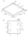
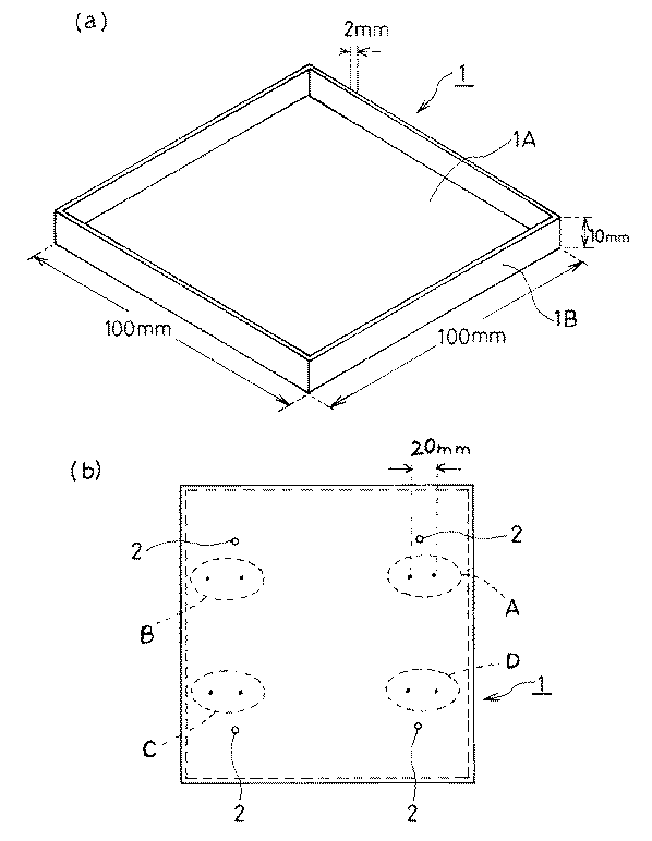
ポリカーボネート樹脂組成物3を用いて、75ton射出成型機にて、シリンダ温度330℃、金型温度90℃にて図1(a)(斜視図)、(b)(平面図)に示すシート1を成形した(なお、図1中、2はピンゲート(直径2mm)のゲート跡である。)。このシート1を粉砕して粒状とした後、再度同条件にて成形及び粉砕を行って組成物3の粒状物を得た。
【0048】
[ポリカーボネート樹脂組成物6]
ポリカーボネート樹脂組成物5をバレル温度320℃、スクリュー回転数300rpmにて2回溶融混練してポリカーボネート樹脂組成物6のペレットを得た。
【0049】
(2)ペレット又は粒状物中のポリカーボネート樹脂の分子量の測定
上述の各組成物中のポリカーボネート樹脂の分子量を以下の要領で測定した。まず、各組成物のクロロホルム溶液(2mg/mL)を調製し、これを0.2μmフィルターにて濾過し、炭素フィブリルを分離してポリカーボネート樹脂溶液を得た。このポリカーボネート樹脂溶液を用いて、ゲルパーミエーションクロマトグラフィーにて下記条件にて重量平均分子量(Mw)を測定した。
【0050】
検出器 :Waters UV490(254nm)
カラム :Shodex GPC AD−806MS
カラム温度:30℃
流量 :1mL/min
内標 :トルエン
注入量 :0.05mL
この測定結果を表1に示す。
【0051】
(3)抵抗値等測定用サンプルの成形
各組成物1〜7を用いて75ton射出成型機により、図1(a),(b)に示す抵抗値測定用サンプルを成形した。成形は、シリンダ温度300℃、金型温度90℃、金型注入速度35〜40cc/secにて行った。
【0052】
なお、用いた金型の、サンプル1のパーティング面1Aに対して90度の面1Bに対応する金型表面粗さは、カットオフ波長2.5mmの測定における10点平均粗さ(Rz)で0.8μmであった。また、成形品の1B面の粗さ(Rz)は0.6μmであった。
【0053】
(4)成形体中のポリカーボネート樹脂の分子量の測定
(3)で得られたサンプルより分子量測定用サンプルをサンプリングし、(2)と同様にしてポリカーボネート樹脂の重量平均分子量(Mw)を測定した。
【0054】
(5)成形体のポリカーボネート樹脂組成物のMFRの測定
(3)で得られたサンプルを粉砕して粒状にした後、280℃、2.16kgの荷重にてメルトフローレート(MFR)を測定した(JIS−7210)。
【0055】
(6)成形体の表面抵抗値の測定
(3)で得られたサンプルについて、ダイヤインスツルメント社製「ハイレスタUP」を使用して、UAプローブ(2探針プローブ、探針間隔20mm)にて印加電圧10Vで図1(b)のA〜D部の表面抵抗値を測定して、平均値を求めた。
【0056】
(7)成形体のアイゾット衝撃強度
ASTM D256(ノッチ付き)に準拠して測定した。
【0057】
実施例1,2、比較例1〜4
表2に示すポリカーボネート樹脂組成物を上述のように成形して各種評価を行い、結果を表2に示した。
【0058】
実施例3
ポリカーボネート樹脂組成物5をA成分とし、ポリカーボネート樹脂組成物3をB成分として、A成分50重量部に対してB成分50重量部を混合したペレットを用いて、実施例1と同様に成形及び評価を行い、結果を表2に示した。
【0059】
実施例4
ポリカーボネート樹脂組成物4をA成分とし、ポリカーボネート樹脂組成物3をB成分として、A成分30重量部に対してB成分70重量部を混合したペレットを用いて、実施例1と同様に成形及び評価を行い、結果を表2に示した。
【0060】
実施例5
ポリカーボネート樹脂組成物6をA成分とし、ポリカーボネート樹脂組成物2をB成分として、A成分40重量部に対してB成分60重量部を混合したペレットを用いて、実施例1と同様に成形及び評価を行い、結果を表2に示した。
【0061】
実施例6
ポリカーボネート樹脂組成物5をA成分とし、ポリカーボネート樹脂組成物2と同様の配合組成のポリカーボネート及び炭素フィブリルマスターバッチ混合物を、B成分として、A成分50重量部に対してB成分50重量部を、2軸混練押出機にて溶融混練した。混練条件は、ポリカーボネート組成物2の混練条件と同様とした。得られた組成物のペレットを用いて、実施例1と同様に成形及び評価を行い結果を表2に示した。
【0062】
【表1】
【表2】
上記結果からも明らかなように、本発明の範囲内であるポリカーボネート成形体は、比較例のものに比べて、同一の炭素フィブリル配合量であるにも関わらず、導電性と衝撃強度に優れている。一方、本発明の範囲外である比較例4では、炭素フィブリルの添加量を増量しているにも関わらず、実施例のものに比較して導電性が大幅に劣っているだけでなく、衝撃強度も低い。
【0065】
特に、ポリカーボネート樹脂のMwが5%以上異なる組成物を混合して得た実施例3〜6の成形体では、導電性はより一層改良されている。
【0066】
【発明の効果】
以上詳述した通り、本発明によれば、少ない炭素フィブリル配合量で高い導電性を発現することができ、従って、安価で衝撃強度等の機械的強度に優れた導電性ポリカーボネート成形体が提供される。
【図面の簡単な説明】
【図1】図1(a)は実施例及び比較例において成形したサンプルを示す斜視図であり、図1(b)は同平面図である。
【符号の説明】
1 サンプル
2 ゲート跡[0001]
BACKGROUND OF THE INVENTION
The present invention relates to a conductive polycarbonate molded body, and more particularly, as an antistatic component in the electric and electronic fields and the automobile field, for example, a packaging member such as a tray, a case, and a package in the manufacture and transportation processes of a semiconductor device, particularly a hard disk. The present invention relates to a conductive polycarbonate molded article suitable as an antistatic member for a drive disk or a magnetic head.
[0002]
[Prior art]
In recent years, semiconductor devices have become extremely vulnerable to static electricity as the information recording density of semiconductor devices increases and the processing speed increases. Has become important.
[0003]
Conventionally, as an antistatic measure, for example, a method of blending and dispersing an antistatic agent, a conductive component such as carbon black, or carbon fiber in a thermoplastic resin such as ABS, polycarbonate, or modified polyphenylene ether (PPE) has been applied. ing.
[0004]
However, these methods have the following problems. That is, in the case of an antistatic agent, it is easily affected by environmental humidity due to the ionic conduction of the conductive mechanism, and the antistatic agent flows out due to washing or long-term use. There is a problem that heat resistance is impaired when added in a large amount. In addition, although carbon black and carbon fiber are not affected by humidity, washing, etc., carbon particles and carbon fiber easily fall off from the molded body, causing problems such as device damage.
[0005]
On the other hand, when carbon fibrils having an average fiber diameter of 200 nm or less are blended as the conductivity-imparting component, since the dropout from the molded body is small, the problem due to detachment is reduced. It is considered that the use of such carbon fibrils is effective as an antistatic measure.
[0006]
[Problems to be solved by the invention]
However, in the case of carbon fibrils, the mechanical strength, particularly the impact strength, is remarkably impaired by adding carbon fibrils, and cracks are likely to occur when the molded product is dropped; Although a compounding amount is required, since carbon fibrils are extremely expensive, this leads to an increase in the cost of the product; if the amount of carbon fibrils added is reduced, the conductivity of the resulting molded body is significantly impaired; There are disadvantages.
[0007]
The present invention solves the above-mentioned conventional problems, and can provide a high conductivity with a low carbon fibril content, and therefore provides a conductive polycarbonate molded article that is inexpensive and excellent in mechanical strength such as impact strength. For the purpose.
[0008]
[Means for Solving the Problems]
The conductive polycarbonate molded body of the present invention is a conductive polycarbonate molded body formed by molding a composition in which 0.1 to 40% by weight of carbon fibrils having an average fiber diameter of 200 nm or less is blended with a polycarbonate resin, and the molded body. The weight average molecular weight of the polycarbonate resin constituting the resin is 30,000 to 45,000.
[0009]
The weight average molecular weight (Mw) of a general polycarbonate resin is, for example, about 50,000 to 60,000 for injection molding, and molding obtained by molding a composition using such a polycarbonate resin of Mw. The Mw of the polycarbonate resin constituting the body is about 45,000 to 55,000. That is, due to the deterioration of the resin due to molding, the Mw of the polycarbonate resin contained in the molded body after molding is lower than before molding.
[0010]
As a result of diligent investigations on the effect of developing conductivity by carbon fibrils, the present inventors have obtained a molded article obtained by molding a composition in which 0.1 to 40% by weight of carbon fibrils having a diameter of 200 nm or less are blended with a polycarbonate resin. A molded body having a Mw of 30,000 to 45,000, which is smaller than the Mw of a polycarbonate resin in a normal polycarbonate resin molded body, exhibits significantly improved conductivity and has a low carbon content. The present inventors have found that excellent conductivity can be obtained with a fibril content, and thus without causing an increase in cost and a decrease in mechanical strength, and the present invention has been completed.
[0011]
Although the details of the mechanism of the effect of improving the conductivity by adopting the polycarbonate resin within the scope of the present invention are not clear, it is estimated as follows.
[0012]
That is, with the flow of the resin during molding, it is considered that the dispersion state of the carbon fibrils is deformed in the flow direction or the carbon fibrils themselves are broken due to strong shear stress particularly near the surface of the molded body. When the molecular weight of the polycarbonate resin, which is a resin, is within the range of the present invention, it is considered that the dispersion of carbon fibrils is less disrupted, and as a result, the carbon fibrils in the molded body function efficiently as a conductive network. .
[0013]
In particular, by using a mixture of the following raw material A and raw material B as the molding raw material, it is possible to obtain a conductive polycarbonate molded body with further improved conductivity and good balance with impact strength.
[0014]
Raw material A: Granule raw material B of polycarbonate resin composition containing carbon fibrils having an average fiber diameter of 200 nm at a ratio of 0.9 to 1.1 times the carbon fibril content of the obtained molded body B: Polycarbonate resin of raw material A The reason why the conductivity is improved by mixing and molding a polycarbonate resin having a Mw of 5% or more and a carbon fibril having an average fiber diameter of 200 nm or less, such that the polycarbonate resin has a Mw of 5% or more is different. However, since the high molecular weight raw material B is kneaded under high viscosity, the dispersion of carbon fibrils becomes good. On the other hand, due to the presence of the low molecular weight raw material A, the above-mentioned dispersion of carbon fibrils is achieved. It is also considered to be a synergistic effect by preventing the destruction of the form.
[0015]
The conductive polycarbonate molded body of the present invention is particularly preferably molded by injection molding.
[0016]
DETAILED DESCRIPTION OF THE INVENTION
Hereinafter, embodiments of the conductive polycarbonate molded body of the present invention will be described in detail.
[0017]
In the present invention, as the polycarbonate resin, for example, a general one produced by reacting a dihydric phenol compound with phosgene by a solution method such as an interfacial polymerization method, a pyridine method, or a chloroformate method can be used. A commercial item can be used for such a polycarbonate resin.
[0018]
The carbon fibrils used in the present invention are carbon fibrils having an average fiber diameter (diameter) of 200 nm or less, and for example, those described in JP-T-8-508534 can be used.
[0019]
Carbon fibrils have a graphite outer layer deposited substantially concentrically along the columnar axis of the fibrils, and the fiber central axis is not straight, but has a undulating and twisted tubular form. The average fiber diameter of the carbon fibril depends on the production method and is almost uniform.
[0020]
If the average fiber diameter of the carbon fibrils is larger than 200 nm, contact between the fibrils in the resin becomes insufficient, and it is difficult to obtain a stable resistance value. Accordingly, carbon fibrils having an average fiber diameter of 200 nm or less are used. In particular, when the average fiber diameter of the carbon fibril is 20 nm or less, the resistance value of the obtained molded body becomes uniform, which is desirable. However, if the average fiber diameter of the carbon fibrils is excessively small, the production becomes extremely difficult. Therefore, the average fiber diameter of the carbon fibrils is preferably 0.1 nm or more, particularly 0.5 nm or more.
[0021]
Further, the carbon fibrils preferably have a length / average fiber diameter ratio (length / diameter) of 5 or more, particularly those having a length / diameter ratio of 100 or more, especially 1000 or more.
[0022]
Moreover, the wall (wall thickness of a tubular body) thickness of the fibril which has a fine tubular form is about 3.5-75 nm normally. This usually corresponds to about 0.1 to 0.4 times the outer diameter of the fibril.
[0023]
In addition, the average fiber diameter and average fiber length (and aspect ratio) of the carbon fibril can be obtained as an average of five actually measured values in observation with a transmission electron microscope.
[0024]
Such carbon fibrils can be commercially available, for example, “BN” manufactured by Hyperion Catalysis International.
[0025]
The compounding quantity of carbon fibril is 0.1 to 40 weight% in a resin composition, Preferably it is 0.5 to 10 weight%, More preferably, it is 1 to 5 weight%. If the blending amount of the carbon fibril is less than this range, the conductivity is not sufficiently exhibited, and if it is more than this range, the moldability is remarkably lowered or the strength of the molded body is lowered.
[0026]
When at least a part of the carbon fibril is in the form of aggregates, the resin composition as a raw material contains fibril aggregates having a diameter of about 50 μm, particularly larger than 10 μm, measured on an area basis. Desirably not.
[0027]
An additional component can be mix | blended with the polycarbonate resin composition which concerns on this invention in the range which does not impair the performance as needed. Examples of such additional components include inorganic fiber reinforcing materials such as glass fiber, silica fiber, silica / alumina fiber, potassium titanate fiber, and aluminum borate fiber, and organic fiber such as aramid fiber, polyimide fiber, and fluororesin fiber. Reinforcing materials, inorganic fillers such as talc, calcium carbonate, mica, glass beads, glass powder, glass balloons, solid lubricants such as fluororesin powder and molybdenum disulfide, plasticizers such as paraffin oil, antioxidants, heat Various additives such as stabilizers, light stabilizers, UV absorbers, neutralizers, lubricants, compatibilizers, antifogging agents, antiblocking agents, slip agents, dispersants, colorants, antibacterial agents, fluorescent whitening agents, etc. An agent can be mentioned.
[0028]
The conductive polycarbonate molded body of the present invention can be produced by an ordinary thermoplastic resin processing method, for example, after previously mixing carbon fibrils and other additional components added as necessary to the polycarbonate resin, A polycarbonate resin composition is manufactured by melt-kneading with a Banbury mixer, roll, Brabender, single-screw kneading extruder, twin-screw kneading extruder, kneader, etc., and then the resin composition is molded by various melt molding methods. Can be manufactured. Specific examples of the molding method include press molding, extrusion molding, vacuum molding, blow molding, injection molding, and the like. Among these molding methods, injection molding is particularly desirable.
[0029]
As injection molding methods, in addition to general injection molding methods, metal parts by insert injection molding method, integral molding with other parts, two-color injection molding method, core back injection molding method, sandwich injection molding method, Various molding methods such as an injection press molding method can be used. In injection molding, since the surface resistance value of a product varies depending on the resin temperature, mold temperature, and molding pressure, it is necessary to set appropriate conditions.
[0030]
In particular, in the present invention, when molding conditions are set so that the Mw reduction of the polycarbonate resin due to injection molding is 2% or more, preferably 2 to 5%, the conductivity of the resulting molded body is improved. desirable.
[0031]
Moreover, a side gate, a film gate, a submarine gate, a pin gate, etc. can be used as a gate (injection port) at the time of inject | pouring a resin composition from the cavity of the metal mold | die in the injection molding method. The sectional area of these gates is preferably 0.2 mm 2 or more.
[0032]
Among them, a pin gate that does not require gate treatment after molding is desirable from the viewpoint of productivity. In that case, the pin gate has a diameter of 0.5 to 3 mm, particularly 1.0 to 2.5 mm. The gate diameter of the pin gate is preferably smaller as long as the resin can be sufficiently filled in the mold, and is generally 0.2 to 0.5 mm. However, in the present invention, when the gate diameter (cross-sectional area) is small, excessive shearing occurs when the resin composition flows through the gate portion, so that the conductive network is easily broken by carbon fibrils. On the other hand, when the gate diameter is too large, the cutting of the gate portion of the molded body is deteriorated and the finish is deteriorated. For this reason, the gate diameter is preferably within the above range.
[0033]
Further, when the molded article of the present invention is molded, since the fluidity of the resin composition is good, the transferability of the mold is good. As described above, when the gate is relatively large, transfer becomes easier. In such a molded mold, it is desirable that the surface of the planar portion having an angle of 80 to 100 degrees (nearly perpendicular) to the parting surface is smooth.
[0034]
That is, if the surface roughness of the surface near the parting surface is rough, the resin transfers this, and the force required to take out the product from the mold increases, resulting in problems such as breakage of the molded body. Therefore, for example, the surface roughness of the surface that is nearly perpendicular to the parting surface is 10 μm or less, preferably 5 μm or less, particularly preferably 10 point average roughness (Rz) in the measurement with a cutoff wavelength of 2.5 mm. Is preferably 3 μm or less.
[0035]
Further, in order to obtain the above fluidity, the melt flow rate (MFR) of the polycarbonate resin composition constituting the molded body of the present invention is 2 to 30 g / 10 min in measurement of 280 ° C. and 2.16 kg load, particularly 4-15 g / 10 min is desirable.
[0036]
When the conductive polycarbonate molded body of the present invention is used as a peripheral part of a semiconductor device, it is desirable that the amount of gas generated from the polycarbonate molded body is particularly small. Specifically, in the measurement by the headspace gas chromatogram, It is desirable that the amount of chlorinated hydrocarbons generated from a surface area of 12.8 cm 2 measured at a temperature of 85 ° C. and an equilibrium time of 16 hours is 0.1 μg / g or less and the total outgas amount is 1 μg / g or less. Therefore, in order to obtain such a molded product, it is desirable to degas volatile components during the production of the resin composition or to use a polycarbonate resin polymerized by a production method that does not use a polymerization solvent.
[0037]
The conductive polycarbonate molded article of the present invention is characterized in that the polycarbonate resin in the molded article has an Mw of 30,000 to 45,000, preferably 35,000 to 43,000. If this Mw is larger than the above range, the conductivity of the molded product is impaired, and the surface resistance value becomes high. If the Mw is smaller than the above range, there are problems such as extremely low impact strength and cracks in the molded product. Arise.
[0038]
As a method for obtaining such a polycarbonate resin molded product within the Mw range, for example, a molded product is produced in advance using a polycarbonate resin having a molecular weight larger than or within the scope of the present invention, and the processing temperature during production is Examples include a method of appropriately reducing the molecular weight of the polycarbonate resin by adjusting conditions and the like, and repeating molding, etc. In particular, a method of melt molding a mixture of the following raw material A and raw material B is easily desirable molecular weight It is preferable because the balance between conductivity and impact strength of the obtained molded body is further improved.
[0039]
Raw material A: Granule raw material B of polycarbonate resin composition containing carbon fibrils having an average fiber diameter of 200 nm at a ratio of 0.9 to 1.1 times the carbon fibril content of the obtained molded body B: Polycarbonate resin of raw material A In this case, when the Mw of the raw material B is not larger than the molecular weight of the Mw of the polycarbonate resin of the raw material A by 5% or more, the impact strength and Little effect of improving conductivity. If this molecular weight is excessively large, it is difficult to adjust the Mw. Therefore, the Mw of the polycarbonate resin of the raw material B is preferably about 5 to 300% (three times) larger than the Mw of the polycarbonate resin of the raw material A. .
[0040]
The ratio of the raw material A in the mixture of the raw material A and the raw material B is preferably 5 to 95% by weight, particularly 10 to 70% by weight, because the effect of improving conductivity is particularly large. Further, the Mw of the polycarbonate resin of the raw material A is desirably 20,000 to 45,000, particularly 30,000 to 43,000.
[0041]
The mixing method of the raw material A and the raw material B is such that when the raw material B is melt-kneaded, the raw material A may be put into a kneading extruder and mixed, or pellets obtained by previously melt-kneading the raw material B may be used. Alternatively, it may be molded after mixing with the raw material A.
[0042]
In addition, as the raw material A, waste products such as trays and cases made of conductive polycarbonate molded bodies used in the semiconductor manufacturing process can be crushed and used. In this case, the waste can be discarded by effectively reusing the waste. It is possible to reduce the amount of materials and the cost of raw materials.
[0043]
【Example】
Hereinafter, the present invention will be described more specifically with reference to Examples and Comparative Examples.
[0044]
In the following, “Iupilon” manufactured by Mitsubishi Engineering Plastics was used as the polycarbonate resin.
[0045]
The carbon fibrils used were “BN” type manufactured by Hyperion Catalysis International. The carbon fibril used was a masterbatch dispersed in a polycarbonate resin at an addition amount of 15% by weight in advance. Moreover, the carbon fibrils dispersed in the resin composition have an average fiber diameter of 10 nm and an average fiber length of 1 μm or more. In addition, the kneading | mixing mixing | blending and shaping | molding of polycarbonate resin 1-6 used by the Example and the comparative example, and the measuring method of various physical properties thru | or a characteristic are as follows.
[0046]
(1) Kneading and blending of polycarbonate resin composition [
Polycarbonate pellets and carbon fibril masterbatch were mixed with the composition shown in Table 1, and using a twin screw extruder ("PCM45" manufactured by Ikekai Steel Co., Ltd., L / D = 32 (L: screw length, D: screw diameter)). The mixture was melt-kneaded at a barrel temperature of 300 ° C. and a screw rotation speed of 160 rpm to obtain pellets of
[0047]
[Polycarbonate resin composition 4]
Using the polycarbonate resin composition 3, the
[0048]
[Polycarbonate resin composition 6]
Polycarbonate resin composition 5 was melt-kneaded twice at a barrel temperature of 320 ° C. and a screw rotation speed of 300 rpm to obtain pellets of polycarbonate resin composition 6.
[0049]
(2) Measurement of molecular weight of polycarbonate resin in pellet or granular material The molecular weight of the polycarbonate resin in each of the above-mentioned compositions was measured as follows. First, a chloroform solution (2 mg / mL) of each composition was prepared and filtered through a 0.2 μm filter to separate carbon fibrils to obtain a polycarbonate resin solution. Using this polycarbonate resin solution, the weight average molecular weight (Mw) was measured by gel permeation chromatography under the following conditions.
[0050]
Detector: Waters UV490 (254 nm)
Column: Shodex GPC AD-806MS
Column temperature: 30 ° C
Flow rate: 1 mL / min
Internal standard: Toluene injection amount: 0.05 mL
The measurement results are shown in Table 1.
[0051]
(3) Molding of Sample for Measuring Resistance Value The samples for measuring resistance value shown in FIGS. 1 (a) and 1 (b) were molded by a 75 ton injection molding machine using each composition 1-7. Molding was performed at a cylinder temperature of 300 ° C., a mold temperature of 90 ° C., and a mold injection rate of 35 to 40 cc / sec.
[0052]
The mold surface roughness of the mold used corresponding to the
[0053]
(4) Measurement of molecular weight of polycarbonate resin in molded body A sample for molecular weight measurement was sampled from the sample obtained in (3), and the weight average molecular weight (Mw) of the polycarbonate resin was measured in the same manner as (2).
[0054]
(5) Measurement of MFR of polycarbonate resin composition of molded article After pulverizing the sample obtained in (3), the melt flow rate (MFR) was measured at 280 ° C. under a load of 2.16 kg. (JIS-7210).
[0055]
(6) Measurement of the surface resistance value of the molded body About the sample obtained in (3), using “Hiresta UP” manufactured by Dia Instruments Co., Ltd., to the UA probe (2 probe probes, probe interval 20 mm). Then, the surface resistance values of the parts A to D in FIG. 1B were measured at an applied voltage of 10 V, and the average value was obtained.
[0056]
(7) Izod impact strength of molded article Measured according to ASTM D256 (with notch).
[0057]
Examples 1 and 2 and Comparative Examples 1 to 4
Various evaluations were performed by molding the polycarbonate resin composition shown in Table 2 as described above, and the results are shown in Table 2.
[0058]
Example 3
Using polycarbonate resin composition 5 as component A and polycarbonate resin composition 3 as component B, 50 parts by weight of component A and 50 parts by weight of component B were molded and evaluated in the same manner as in Example 1. The results are shown in Table 2.
[0059]
Example 4
Using polycarbonate resin composition 4 as component A, polycarbonate resin composition 3 as component B, and pellets obtained by mixing 70 parts by weight of component B with 30 parts by weight of component A, molding and evaluation in the same manner as in Example 1. The results are shown in Table 2.
[0060]
Example 5
Using polycarbonate resin composition 6 as component A and
[0061]
Example 6
Polycarbonate resin composition 5 as component A, polycarbonate and carbon fibril masterbatch mixture having the same composition as
[0062]
[Table 1]
[Table 2]
As is clear from the above results, the polycarbonate molded body within the scope of the present invention is superior in conductivity and impact strength to the comparative example, despite having the same carbon fibril content. Yes. On the other hand, in Comparative Example 4, which is outside the scope of the present invention, not only the conductivity of the Example was significantly inferior to that of the Example, although the amount of carbon fibril added was increased. The strength is also low.
[0065]
In particular, in the molded bodies of Examples 3 to 6 obtained by mixing compositions having a polycarbonate resin having a Mw different by 5% or more, the conductivity is further improved.
[0066]
【The invention's effect】
As described above in detail, according to the present invention, a conductive polycarbonate molded body that can exhibit high conductivity with a small amount of carbon fibril blended, and is therefore inexpensive and excellent in mechanical strength such as impact strength is provided. The
[Brief description of the drawings]
FIG. 1 (a) is a perspective view showing samples molded in Examples and Comparative Examples, and FIG. 1 (b) is a plan view of the same.
[Explanation of symbols]
1
Claims (3)
原料A:得られる成形体の炭素フィブリル含有量に対して0.5〜1.5倍の割合で平均繊維径200nm以下の炭素フィブリルを含むポリカーボネート樹脂組成物の粒状体
原料B:原料Aのポリカーボネート樹脂よりも重量平均分子量が5%以上大きいポリカーボネート樹脂及び平均繊維径200nm以下の炭素フィブリル2. A conductive polycarbonate molded article according to claim 1, wherein the mixture of the following raw material A and raw material B is melt-molded.
Raw material A: Granule raw material B of polycarbonate resin composition containing carbon fibrils having an average fiber diameter of 200 nm or less at a ratio of 0.5 to 1.5 times the carbon fibril content of the obtained molded body B: Polycarbonate of raw material A Polycarbonate resin having a weight average molecular weight of 5% or more larger than the resin and carbon fibrils having an average fiber diameter of 200 nm or less
Priority Applications (1)
| Application Number | Priority Date | Filing Date | Title |
|---|---|---|---|
| JP2000126110A JP4491908B2 (en) | 2000-04-26 | 2000-04-26 | Conductive polycarbonate molding |
Applications Claiming Priority (1)
| Application Number | Priority Date | Filing Date | Title |
|---|---|---|---|
| JP2000126110A JP4491908B2 (en) | 2000-04-26 | 2000-04-26 | Conductive polycarbonate molding |
Publications (2)
| Publication Number | Publication Date |
|---|---|
| JP2001310994A JP2001310994A (en) | 2001-11-06 |
| JP4491908B2 true JP4491908B2 (en) | 2010-06-30 |
Family
ID=18635950
Family Applications (1)
| Application Number | Title | Priority Date | Filing Date |
|---|---|---|---|
| JP2000126110A Expired - Lifetime JP4491908B2 (en) | 2000-04-26 | 2000-04-26 | Conductive polycarbonate molding |
Country Status (1)
| Country | Link |
|---|---|
| JP (1) | JP4491908B2 (en) |
Families Citing this family (7)
| Publication number | Priority date | Publication date | Assignee | Title |
|---|---|---|---|---|
| JP4765163B2 (en) * | 2000-12-05 | 2011-09-07 | 油化電子株式会社 | Conductive resin composition and conductive injection molded product |
| JP2005036200A (en) * | 2003-06-26 | 2005-02-10 | Mitsubishi Gas Chem Co Inc | Thermoplastic resin composition and molded article thereof |
| JP5074011B2 (en) * | 2006-11-24 | 2012-11-14 | 三菱エンジニアリングプラスチックス株式会社 | Polycarbonate resin composition and resin molded body formed by molding the same |
| JP4936026B2 (en) | 2009-04-02 | 2012-05-23 | 宇部興産株式会社 | Method for producing conductive binder |
| CN102575101B (en) | 2009-08-07 | 2013-10-09 | 宇部兴产株式会社 | Conductive polyamide resin composition |
| BR112012005041A2 (en) | 2009-09-07 | 2016-05-03 | Ube Industries | multilayer tube for transport. |
| JP7806477B2 (en) * | 2021-12-16 | 2026-01-27 | 三菱ケミカル株式会社 | Crushed material, material, compact, and method for manufacturing compact |
Family Cites Families (3)
| Publication number | Priority date | Publication date | Assignee | Title |
|---|---|---|---|---|
| JP2001256621A (en) * | 2000-03-10 | 2001-09-21 | Alps Electric Co Ltd | Magneto-resistive head transport tray for magnetic disks |
| JP4161428B2 (en) * | 1998-10-08 | 2008-10-08 | アルプス電気株式会社 | Magnetoresistive head transport tray for magnetic disks |
| JP4239348B2 (en) * | 1999-08-06 | 2009-03-18 | アルプス電気株式会社 | Transport tray for magnetic head for magnetic disk |
-
2000
- 2000-04-26 JP JP2000126110A patent/JP4491908B2/en not_active Expired - Lifetime
Also Published As
| Publication number | Publication date |
|---|---|
| JP2001310994A (en) | 2001-11-06 |
Similar Documents
| Publication | Publication Date | Title |
|---|---|---|
| CN1392892A (en) | Polyphenyleneoxide-based composite resin composition for IC tray | |
| Jang | Low-density polycarbonate composites with robust hollow glass microspheres by tailorable processing variables | |
| JP4491908B2 (en) | Conductive polycarbonate molding | |
| JP4937523B2 (en) | COMPOSITE COMPOSITION AND PROCESS FOR PRODUCING THE SAME | |
| JP5715484B2 (en) | Process for producing conductive polyphenylene ether resin composition | |
| JP5252713B2 (en) | Molded body of aromatic polycarbonate resin composition | |
| JP4889460B2 (en) | Conductive resin composition for semiconductor transport container parts, semiconductor transport container parts using the same, and semiconductor transport container | |
| JPH05255520A (en) | Production of sliding member | |
| CN114127190A (en) | Polycarbonate resin composition | |
| KR20170112929A (en) | Electro-conductive polymer composite and resin composition having improved impact strength and method for preparing the same | |
| JPH01259059A (en) | Resin composition | |
| WO2019181828A1 (en) | Electrically conductive resin composition and method for producing same | |
| JP2002079515A (en) | Method for manufacturing thermoplastic resin composition and rubber composition | |
| JP4765163B2 (en) | Conductive resin composition and conductive injection molded product | |
| JP2005062835A (en) | Lens barrel | |
| JP2002275276A (en) | Conductive molded products | |
| JP2979045B2 (en) | Polyarylene sulfide resin composition | |
| EP3626778B1 (en) | Electrically conductive resin composition and preparation method thereof | |
| JP3790742B2 (en) | Conductive polycarbonate resin composition and molded article comprising the same | |
| JP4265328B2 (en) | Polyarylene sulfide resin composition and molded article using the same | |
| KR102172554B1 (en) | Polycarbonate resin composition, method for preparing the resin composition and molded article comprising the same | |
| JP5220715B2 (en) | Aromatic polycarbonate resin composition and molded article thereof | |
| JP4039886B2 (en) | Conductive molding | |
| CN114302916B (en) | Polyamide resin composition for sliding parts and sliding parts | |
| JP2001323150A (en) | Conductive resin composition |
Legal Events
| Date | Code | Title | Description |
|---|---|---|---|
| A621 | Written request for application examination |
Free format text: JAPANESE INTERMEDIATE CODE: A621 Effective date: 20070228 |
|
| A977 | Report on retrieval |
Free format text: JAPANESE INTERMEDIATE CODE: A971007 Effective date: 20100310 |
|
| TRDD | Decision of grant or rejection written | ||
| A01 | Written decision to grant a patent or to grant a registration (utility model) |
Free format text: JAPANESE INTERMEDIATE CODE: A01 Effective date: 20100316 |
|
| A01 | Written decision to grant a patent or to grant a registration (utility model) |
Free format text: JAPANESE INTERMEDIATE CODE: A01 |
|
| A61 | First payment of annual fees (during grant procedure) |
Free format text: JAPANESE INTERMEDIATE CODE: A61 Effective date: 20100329 |
|
| R150 | Certificate of patent or registration of utility model |
Free format text: JAPANESE INTERMEDIATE CODE: R150 |
|
| FPAY | Renewal fee payment (event date is renewal date of database) |
Free format text: PAYMENT UNTIL: 20130416 Year of fee payment: 3 |
|
| FPAY | Renewal fee payment (event date is renewal date of database) |
Free format text: PAYMENT UNTIL: 20140416 Year of fee payment: 4 |
|
| R250 | Receipt of annual fees |
Free format text: JAPANESE INTERMEDIATE CODE: R250 |
|
| R250 | Receipt of annual fees |
Free format text: JAPANESE INTERMEDIATE CODE: R250 |
|
| R250 | Receipt of annual fees |
Free format text: JAPANESE INTERMEDIATE CODE: R250 |
|
| R250 | Receipt of annual fees |
Free format text: JAPANESE INTERMEDIATE CODE: R250 |
|
| R250 | Receipt of annual fees |
Free format text: JAPANESE INTERMEDIATE CODE: R250 |
|
| R250 | Receipt of annual fees |
Free format text: JAPANESE INTERMEDIATE CODE: R250 |