JP4491896B2 - Energization control device - Google Patents
Energization control device Download PDFInfo
- Publication number
- JP4491896B2 JP4491896B2 JP2000056790A JP2000056790A JP4491896B2 JP 4491896 B2 JP4491896 B2 JP 4491896B2 JP 2000056790 A JP2000056790 A JP 2000056790A JP 2000056790 A JP2000056790 A JP 2000056790A JP 4491896 B2 JP4491896 B2 JP 4491896B2
- Authority
- JP
- Japan
- Prior art keywords
- time
- information
- energization
- energization control
- controller
- Prior art date
- Legal status (The legal status is an assumption and is not a legal conclusion. Google has not performed a legal analysis and makes no representation as to the accuracy of the status listed.)
- Expired - Fee Related
Links
Images


Landscapes
- Feedback Control In General (AREA)
- Control Of Electrical Variables (AREA)
Description
【0001】
【発明の属する技術分野】
本発明は、電気機器の使用状況に応じて電気機器の運転状態を制御する機器に関するものである。
【0002】
【従来の技術】
従来から使用されている通電制御装置の一例を図19を使用して説明する。従来の通電制御装置5は、商用電源1のコンセント2と、電気機器3のプラグ4の間に接続されている。通電制御装置5は、コンセント2とプラグ4の間をつなぐ線路を有しており、コンセント2にはプラグ6、プラグ4にはコンセント7を接続している。また、線路は途中に通電制限用のスイッチ8を有しいる。電気機器3は、電気洗濯機、ジャーポット、ジャー炊飯器、テレビあるいは温水洗浄暖房便座などの一般の電気機器であり、4は電気機器が有しているプラグである。
【0003】
この装置を用いて、省エネルギー、省電力などの目的で電気機器3への通電を停止するときは、スイッチ8を押すことによって回路を開き、商用電源1の通電を停止する。また電気機器3へ通電するときは、再びスイッチ8を押すことによって回路を閉じるものである。
【0004】
【発明が解決しようとする課題】
前記従来の通電制御装置は、十分な省エネ、省電力効果が発揮できないという課題を有している。すなわち、使用者が逐一スイッチを押す必要があって、使用者の意識に全面的に負っているものである。従って省エネ、省電力を実行する習慣が長続きしない、また、その制御のタイミングが正しいものかどうかは疑問が残る装置となっている。また、使用者が不在である時は作動させることができないものとなっている。
【0005】
【課題を解決するための手段】
本発明は、使用者が逐一スイッチ等を押すことなく、電気機器の特性や使用実態等を電力データなどを用いて通電制御信号として作成し、自動的に省エネ、省電力を実現する通電制御装置としている。
【0006】
【発明の実施の形態】
請求項1に記載した発明は、商用電源と電気機器との間の電線路の通電と遮断を行うアダプタと、通信を行うコントローラにおいて、アダプタと情報の送受信を行うコントローラ送受信手段と、時刻を測定するタイマ手段と、タイマ手段で測定された時間情報と、コントローラ送受信手段で受信した電線路における電流情報と電圧情報を演算して得られる電力情報と、を保存するデータ記憶手段と、データ記憶手段に記憶されている時間情報と電力情報とに基づいて所定時間毎の使用可能性データを更新し、使用可能性データを閾値と比較することにより通電制御可能時間を生成する機器使用状態学習・予測手段と、通電制御可能時間の時間帯に応じて通電制御信号をコントローラ送受信手段からアダプタへと送信させ、電線路を遮断させる、もしくは電線路の通電率を制限させるコントローラ制御手段と、を備えたコントローラとしている。
【0007】
請求項2に記載した発明は、機器使用状態学習・予測手段は、データ記憶手段に保存されている時間情報と電力情報とから電気機器の使用の有無を判断し、使用の有無に重み付けを行うことで所定時間毎の使用可能性データを更新するコントローラとしている。
【0008】
請求項3に記載した発明は、コントローラは、閾値変更手段を備え、閾値変更手段は、使用可能性データが閾値変更用閾値を超えたとき閾値を変更するコントローラとしている。
【0009】
請求項4に記載した発明は、商用電源と電気機器との間の電線路の通電と遮断を行う通電制御装置において、電気機器に供給される電流と電圧とを検出する検出手段と、コントローラ送受信手段と情報の送受信を行うアダプタ送受信手段と、電線路を遮断する、もしくは電線路の通電率を制限する通電制御手段と、アダプタ送受信手段に検出手段で検出した電流情報と電圧情報とを送信させ、アダプタ送受信手段で受信した通電制御信号に応じて通電制御手段を制御するアダプタ制御手段と、を含むアダプタと、アダプタ送受信手段と情報の送受信を行うコントローラ送受信手段と、時刻を測定するタイマ手段と、タイマ手段で測定された時間情報と、コントローラ送受信手段で受信した電流情報と電圧情報を演算して得られる電力情報と、を保存するデータ記憶手段と、データ記憶手段に記憶されている時間情報と電力情報とに基づいて所定時間毎の使用可能性データを更新し、使用可能性データを閾値と比較することにより通電制御可能時間を生成する機器使用状態学習・予測手段と、通電制御可能時間の時間帯に応じて通電制御信号をコントローラ送受信手段からアダプタ送受信手段へと送信させるコントローラ制御手段と、を含むコントローラと、を備えた通電制御装置としている。
【0010】
請求項5に記載した発明は、機器使用状態学習・予測手段は、データ記憶手段に保存されている時間情報と電力情報とから電気機器の使用の有無を判断し、使用の有無に重み付けを行うことで所定時間毎の使用可能性データを更新する通電制御装置としている。
【0011】
請求項6に記載した発明は、コントローラは、閾値変更手段を備え、閾値変更手段は、使用可能性データが閾値変更用閾値を超えたとき閾値を変更する通電制御装置としている。
【0012】
請求項7に記載した発明は、アダプタは、電気機器が操作されたことを示す信号を機器から受信する機器使用情報受信手段を備え、機器使用状態学習・予測手段は、時間情報と電力情報と電気機器が操作されたことを示す信号とに基づいて通電制御可能時間を生成する通電制御装置としている。
【0013】
請求項8に記載した発明は、アダプタは、通電制御を開始する前の電気機器の動作状態を示す情報を電気機器から受信するアダプタ側機器制御情報送受信手段を備え、アダプタ側機器制御情報送受信手段は、通電制御終了時に機器制御手段の動作状態を元に戻す信号を機器に送信する通電制御装置としている。
【0014】
請求項9に記載した発明は、アダプタは、使用者に通電制御が不可能な時間帯を入力させる通電制御不可時間入力手段を備えた通電制御装置としている。
【0015】
請求項10に記載した発明は、コントローラに、室内の温度データを測定する室内温度測定アダプタを接続した通電制御装置としている。
【0016】
請求項11に記載した発明は、コントローラに、室外の温度データを測定する室外温度測定アダプタを接続した通電制御装置としている。
【0017】
請求項12に記載した発明は、コントローラは、データ記録手段が記憶しているデータを複製するデータ複製手段を備えた通電制御装置としている。
【0018】
請求項13に記載した発明は、電気機器に供給される電流と電圧とを検出する検出ステップと、時刻を測定する計時ステップと、計時ステップで測定された時間情報と、検出ステップで検出された電流と電圧とから演算される電力情報を保存するデータ記憶ステップと、時間情報と電力情報とに基づいて所定時間毎の使用可能性データを更新する更新ステップと、更新ステップで更新された使用可能性データと閾値とを比較することにより通電制御可能時間を生成する生成ステップと、生成ステップで生成された通電制御可能時間の時間帯に達したことを確認すると、商用電源と電気機器との間の電線路を遮断する、もしくは電線路の通電率を制限する通電制限ステップと、を備えた通電制御方法としている。
【0019】
請求項14に記載した発明は、電気機器に供給される電流と電圧とを検出する検出ステップと、時刻を測定する計時ステップと、計時ステップで測定された時間情報と、検出ステップで検出された電流と電圧とから演算される電力情報を保存するデータ記憶ステップと、時間情報と電力情報とに基づいて電気機器の使用の有無を判断し、使用の有無に重み付けを行うことで所定時間毎の使用可能性データを更新する更新ステップと、更新ステップで更新された使用可能性データと閾値とを比較することにより通電制御可能時間を生成する生成ステップと、生成ステップで生成された通電制御可能時間の時間帯に達したことを確認すると、商用電源と電気機器との間の電線路を遮断する、もしくは電線路の通電率を制限する通電制限ステップと、を備えた通電制御方法としている。
【0020】
請求項15に記載した発明は、電気機器に供給される電流と電圧とを検出する検出ステップと、時刻を測定する計時ステップと、計時ステップで測定された時間情報と、検出ステップで検出された電流と電圧とから演算される電力情報を保存するデータ記憶ステップと、時間情報と電力情報とに基づいて電気機器の使用の有無を判断し、使用の有無に重み付けを行うことで所定時間毎の使用可能性データを更新する更新ステップと、使用可能性データが閾値変更用閾値を超えたとき閾値を変更する閾値変更ステップと、更新ステップで更新された使用可能性データと閾値とを比較することにより通電制御可能時間を生成する生成ステップと、生成ステップで生成された通電制御可能時間の時間帯に達したことを確認すると、商用電源と電気機器との間の電線路を遮断する、もしくは電線路の通電率を制限する通電制限ステップと、を備えた通電制御方法としている。
【0021】
【実施例】
(実施例1)
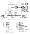
以下、本発明の第1の実施例について説明する。図1は本実施例の構成を示すブロック図である。本実施例の通電制御装置は、商用電源1と電気機器3との間に接続した、アダプタ101とコントローラ102とによって構成している。アダプタ101は、商用電源1に接続しているコンセント2に接続するプラグ3と、電気機器3が有しているプラグ4が接続されるアダプタコンセント104と、この間を接続する線路を有している。前記線路には、電力検出手段105と、電力検出手段105の電力情報を受けて、前記線路に設けている通電制限手段110の開閉を制御する駆動手段111を制御するアダプタ制御手段112と、アダプタ制御手段112の指示によってコントローラ102に前記電力情報を示す情報を送信する送受信手段108を設けている。
【0022】
前記電気機器3としては、電気洗濯機、ジャーポット、ジャー炊飯器、テレビ、温水洗浄暖房便座などが使用できる。
【0023】
また、電流検出手段106としては、カレントトランスやホール素子を用いた電流センサやシャント抵抗が使用できる。電圧検出手段107としては、トランスが使用できる。アダプタ送受信手段108としては、電力搬送通信手段や赤外通信手段や微弱無線通信手段や特定小電力無線通信手段が使用できる。また通電制限手段110としては、リレーやIGBTなどの半導体スイッチング素子が使用できる。またアダプタ制御手段112にとしては、本実施例ではマイクロコンピュータを使用している。
【0024】
またコントローラ102は、前記アダプタ送受信手段108が送信する電力情報を受けるコントローラ送受信手段113と、タイマ手段114と、データ記憶手段115と、機器使用状態学習・予測手段116と、コントローラ制御手段117を有している。前記各手段にはマイクロコンピュータを使用しており、コントローラ制御手段117は、コントローラ送受信手段113から電力情報を受けると、データ記憶手段115にこの電力情報を保存し、同時に機器使用状態学習・予測手段116に、前記電気機器3の使用状態を学習させ、また電気機器3の通電制御可能時間を予測させるものである。また、コントローラ制御手段117は、こうして機器使用状態学習・予測手段116から予測した電気機器3の通電制御可能時間から、通電の必要のない時間帯に達したことを認識すると、コントローラ送受信手段113に電気機器3への通電を停止する信号を送るものである。また同様に電気機器3が使用される時間帯に達したときは、コントローラ送受信手段113に電気機器3に対する通電を実行する信号を送るものである。このコントローラ送受信手段113が受けた信号は、アダプタ101のアダプタ送受信手段108からアダプタ制御手段112に伝達されるものである。
【0025】
つまり、アダプタ101とコントローラ102とは双方向の通信を行っているものである。アダプタ制御手段112は、コントローラ102から受けた信号が電気機器3に対する通電であれば、駆動手段111を駆動して、通電制御手段110を閉じる、あるいは通電デューティを100%通電となるように、または必要な通電率となるように通電デューティを制御する。また、コントローラ102から受けた信号が電気機器3に対する通電が不要である場合は、駆動手段111を駆動して、通電制御手段110を開く、あるいは0%通電となるように通電デューティを制御する。
【0026】
以下、本実施例の動作について説明する。コントローラ102は、コントローラ制御手段116により動作制御が行われている。すなわち、タイマ手段114が出力するサンプリングタイムに基づき、アダプタ101に対して、電力情報を観測しデータを送るように指示する。この指示は、コントローラ送受信手段113から、アダプタ101のアダプタ送受信手段108を通じて、アダプタ制御手段112に対して行われる。アダプタ制御手段112は、電力検出手段105を構成する電流検出手段106および電圧検出手段107を駆動して、電気機器3に流れている電流および電圧を測定させる。また、この電流信号と電圧信号を電力情報として、アダプタ送受信手段108からコントローラ送受信113に通信する。コントローラ制御手段117は、コントローラ送受信手段113から得られた電流情報と電圧情報を加工して電力データの演算を行い、タイマ手段114の時間情報と共にデータ記憶手段115に記憶させる。
【0027】
機器使用状態学習・予測手段116は、データ記憶手段115が記憶している前記電力データについて学習する。すなわち、ある時刻から電気機器3が消費する電力が急激に増加したような場合、その時刻の前後の状態も併せて記憶するものである。つまり、電気機器3の種類によっては、予備動作があって、本動作に入って、更に終了動作に入るものである。このような場合、各動作での消費電力は異なる場合が普通であり、本実施例の機器使用状態学習・予測手段116はこの一連の状態を学習して記憶する。更にこの記憶したデータから、タイマ手段114が出力する現在の時刻が、通電制御を行うべき時刻であるかどうかを判断して、コントローラ制御手段117にこの情報を伝達するものである。コントローラ制御手段117は、通電制御の可あるいは不可に応じた信号を、コントローラ送受信手段113からアダプタ送受信手段108に伝達するものである。アダプタ制御手段112は、コントローラ制御手段117からの指示に基づいて、駆動手段111を駆動して、通電制御手段110を動作させる。すなわち、通電制限手段110を開く、あるいは閉じる、または必要な時間の通電が行えるように通電デューティを制御するものである。
【0028】
次に本実施例で使用している機器使用状態学習・予測手段116が行う学習動作について、具体的に説明する。機器使用状態学習・予測手段116が学習を行う際は、データ記憶手段115が記憶している使用時間のデータと、電気機器3の使用電力のデータを用いている。機器使用学習状態学習・予測手段116は、待機電力より多くの電力を消費している時間を電気機器3が使用されている時間と判断し、所定時間毎(例えば10分)に設けられた記憶領域の使用可能性データを更新する。この際、電気機器3が使用されている場合は加算を行い(例えば+3)、使用されていない場合は減算を行う(−1)。このように電気機器3の使用可能性データを、電気機器3が使用されている時と使用されていない時の両方を学習することで、図2に示すような使用可能性グラフが得られる。これを機器使用状態予測に利用し、図2に示したように閾値(ここでは−7)よりも下の時間帯を通電制御可能時間と判断する。このように、不使用時間の可能性を減らしていくことによって、電気機器3の不使用時間帯の通電制御が行われるものである。
【0029】
以上のように本実施例によれば、アダプタ101に接続した電気機器3の電力情報を基に、コントローラ102が電力使用の時系列データと、電気機器3の使用時間または不使用時間、あるいはこれらの状況の頻度を学習することによって、電気機器3の通電制御可能時間を予測できるものであり、この予測に基づいて電気機器3の最適な通電状態を実現する制御信号を出力して、電気機器3の待機電力や保温電力を削減できるものである。すなわち、省エネルギー、省電力に大きな効果を有する通電制御装置を実現するものである。
【0030】
なお、本実施例では電気機器3が使用されている判断を、待機電力より多い場合として説明を行ったが、電力推移などから推定した結果を用いてもよいことは明らかである。
【0031】
(実施例2)
続いて、本発明の第2の実施例について説明する。図3は本実施例の構成を示すブロック図である。本実施例では、コントローラ102は接続機器認識手段301を備えている。接続機器認識手段301はマイクロコンピュータを用いているもので、接続された電気機器3の種類を特定するものである。
【0032】
以下、本実施例の動作について説明する。例えば、アダプタ101に接続されている電気機器3がジャーポットであった場合は、電気機器3が使用される時には、所望の温度の水になっていることが必要である。しかし、通電制御が行われた状態から復帰した場合は、ジャーポット内の水の温度は直ちには復帰できない。このように通電制御から復帰したときに、準備動作が必要な電気機器が電気機器3として接続されている場合は、通電制御から復帰した後の使用電力の推移は、最大電力運転を行った後に待機電力に戻るという形になる。
【0033】
接続機器認識手段301は、データ記憶手段115が記憶している電気機器3の使用電力の推移を分析し、通電制御から復帰した後の電力推移が準備動作を行っているかどうかを判定する。また、電気機器3が準備動作を行っていると判定した場合、接続機器認識手段301は、機器使用状態学習・予測手段116に指示を出して、学習を行う際に、電気機器3が使用されている場合の使用可能性データを加算する時に、予備動作の必要な時間だけ前の時間帯のものも加算させているものである。例えば、予備動作が15分であれば、20分前のデータまで加算させている。
【0034】
以上のように本実施例によれば、コントローラ102に接続機器認識手段301を接続した構成とすることによって、アダプタ101に接続した電気機器3が、予備動作を必要とする場合も、予め予備動作を考慮した機器使用状態学習を行うことによって、使用者の不便が起こらないようにした上で、電気機器の待機電力削減や保温電力削減などの省エネルギー、省電力に大きな効果を有する通電制御装置を実現できるものである。
【0035】
(実施例3)
続いて、本発明の第3の実施例について説明する。図4は本実施例の構成を示すブロック図である。本実施例では、コントローラ102が行う学習は、ファジィ集合による広がりを有するデータを使用して行っているものである。
【0036】
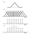
以下、本実施例の機器使用学習・予測手段401の学習動作について説明する。本実施例の機器使用学習・予測手段401は、入力部として、図5(a)に示すような二等辺三角型のファジィ集合μiを、横軸に時刻をとって、二等辺三角形の頂点と底辺の関係が図5(b)にある関係となるよう所定時間間隔に並べ(例えば頂点の間隔が10分)、2重に交わるような形に構成している。また、学習・予測演算用のデータには、各ファジィ集合μiに対応する実数値Riを用いている。
【0037】
ここで時刻tに電気機器3が使用された場合を用いて、機器使用学習・予測手段401が行う学習動作について説明する。図5(b)に示しているように、時刻tに電気機器3が使用された場合、入力部のファジィ集合で値を持つのはμ2,μ3,μ4,μ5となる。つまり、必ず4つのファジィ集合が値を持つものである。ファジィ集合μiが値μi(t)を持つ場合は、機器使用学習・予測手段401は電気機器3が使用されている状態であるとみなして対応する実数値Riの値を加算更新して、データ記憶手段115に保存する。このとき使用時の学習係数をα(例えば0.5)とすると、更新されるRiはRi=Ri+α*μi(t)*Riで表される(ここではi=2,3,4,5)。一方、ファジィ集合μ1,μ6,μ7,μ8は値を持たない。これらに対応する実数値Riについては、機器使用学習・予測手段401は電気機器3が不使用状態であると学習して、データ記憶手段115に保存する。不使用時の学習係数をβ(例えば0.9)とすると、更新されるRiはRi=β*Ri(ここではi=1,6,7,8)で表される。このような動作によって、機器使用学習・予測手段401は電気機器3の使われ方を学習する。また学習後にデータ記憶手段115に記憶する実数値Riは、図5(c)に示しているように変更される。
【0038】
次に、機器使用学習・予測手段401の予測動作について説明する。学習した時と同時刻t、すなわち図5(b)に示している時刻tにおける電気機器3の通電制御の可能性は、時刻tにおいて値を持つファジ集合の度合いをμ2(t),μ3(t),μ4(t),μ5(t)とすると、(数1)に示すような重心演算によって求められる。
【0039】
【数1】

【0040】
【数2】
【0041】
以上のように本実施例によれば、機器使用状態学習・予測手段401が、ファジィ集合によって予め広がりを有するデータを使用して電気機器3の使用状態を学習し、またこの学習によって電気機器3の通電制御の可能性を演算予測するようにして、正確な制御ができる通電制御装置を実現するものである。
【0042】
(実施例4)
以下、本発明の第4の実施例について説明する。図6は本実施例の構成を示すブロック図である。本実施例では、コントローラ102にニューラルネット手段601を設けている。ニューラルネット手段601にはマイクロコンピュータを用いており、自己組織型のニューラルネットワークを使用している。ニューラルネット手段601は、機器使用状態学習・予測手段116とデータ記憶手段115に接続している。
【0043】
以下本実施例の動作について説明する。電気機器3の使用者の日常の生活パターンは、平日と休日とでは大きく異なる場合が多い。例えば、休日に外出することの多い使用者の場合、外出時の電気機器3の利用が少なくなるため、通電制御を行うことのできる時間帯が平日より増える。そのため、これらを自動的に区別するため、ニューラルネット手段601には自己組織型のニューラルネットワークを使用し、データ記憶手段105が記憶している所定の時間毎(例えば10分毎)に、電気機器3の電力消費量と使用頻度のデータをアダプタ101に要求して、コントローラ送受信手段113からこのデータを受けるものである。本実施例のニューラルネット手段601は、自己組織型としているため、入力データから2つの集合を作るようにデータの結合を行うものである。従って使用者が電気機器3を使用すると、自動的に2つのパターンに区別するものである。ニューラルネット手段601は、出力するパターンを機器使用学習・予測手段116に知らせ、学習および予測に用いるデータをパターンによって切り替えるよう指示する。このように、生活パターンを区別して学習・予測を行うことで、電気機器3に対する通電制御の可能性のある時間帯の判断の精度が高まるものであり、機器使用学習・予測手段116はより長く通電制御を行うことができるようになる。
【0044】
以上のように本実施例によれば、ニューラルネット手段601を使用しているため、使用者の生活状況のパターン毎に、電気機器3の使用状況を学習できるため、電気機器3の通電制御を行う時間帯の予測精度を高め、更なる省エネルギーを行うことができる通電制御装置を提供することができる。
【0045】
なお、本実施例では平日と休日の2つのパターンに分ける場合について説明したが、使用者からのパターン数の入力などによって、より多くのパターンに分けても構わないことは言うまでもない。
【0046】
(実施例5)
続いて本発明の第5の実施例について説明する。図7は本実施例の構成を示すブロック図である。本実施例では、コントローラ102に閾値変更手段701を設けている。閾値変更手段701にはマイクロコンピュータを用いている。
【0047】
図8は本実施例の閾値変更手段701の動作を説明する説明図である。図8に示している時間帯tは、このデータでは電気機器3が使用されていない時間帯となっている。しかしこの時間帯は、本来は頻繁に電気機器3が使用されているものである。本実施例は、このような偶然によるデータを排除することによって、機器使用状態学習・予測手段116が正しい学習が行えて、電気機器3の通電制御を行う時間帯の正確な予想ができる通電制御装置としているものである。
【0048】
すなわち、制御を行うための閾値を一定としてあれば、前記時間帯tは通電制御の対象とされるものである。本実施例では、閾値変更手段701は、電気機器3の通電制御の可能時間を判定するための閾値を変更するための閾値(例えば10)を有している。こうしてこの閾値を超えた後の例えば20分間という所定時間の間は、通電制御可能時間判定のための閾値を例えば−10という所定値だけ低下させるようにしているものである。このため、使用頻度の高い時間帯には通電制御が行われ難くするものである。
【0049】
以上のように本実施例によれば、コントローラ102に閾値変更手段701を使用することによって、電気機器3の通電制御可能時間の予測のための閾値を、電気機器3のの使用状況を考慮して変更することができ、機器使用状況を学習する際に、電気機器3が偶然使われなかった時間帯を電気機器3の通電制御可能時間と誤判定することがない通電制御装置を実現するものである。
【0050】
(実施例6)
続いて本発明の第6の実施例について説明する。図9は本実施例の構成を示すブロック図である。本実施例では、コントローラ102に表示手段901を設けている。表示手段901には液晶表示器を用いている。
【0051】
次に動作について説明を行う。コントローラ制御手段117は、実施例1と同様に動作して、電気機器3の通電制御可能時間帯の判断を行う。ここで、コントローラ制御手段117は、タイマ手段114からの時間情報に基づいて、例えば24時間という所定時間毎に通電制御動作の予定時間を演算して、この予定の時間帯を表示手段901に表示するものである。
【0052】
以上のように本実施例によれば、コントローラ102に表示手段901を設けた構成として、コントローラ102が次回の通電制御の予定時間を表示することができ、使用者に省エネルギー、省電力の動機付けを行うことができる通電制御装置を実現できるものである。
【0053】
(実施例7)
以下、本発明の第7の実施例について説明する。図10は本実施例の構成を示すブロック図である。本実施例では、電気機器3は機器の使用状況を示す送信手段1001を備えている。前記送信手段1001は、例えば電気機器3がジャーポットである場合には給湯スイッチに連動して信号を発生するものである。つまり、給湯スイッチが入れられると機器が使用されているという信号を発生するものである。また、アダプタ101にはこの信号を受ける受信手段1002を設けている。前記受信手段1002が受けた信号は、アダプタ制御手段112に伝達されるようになっている。なお本実施例では、前記送信手段1001と受信手段1002として、電気的な接続を使用したり、あるいは電力線搬送通信や赤外通信または無線通信等の手段を使用できるものである。
【0054】
以下、本実施例の動作について説明する。電気機器3が例えばジャーポットである場合には、通常時にはジャーポットないの水を保温するのに必要な保温電力だけを消費しているものである。つまり、アダプタ101の電力検出手段105による電力の検出だけでは、使用者による給湯動作を検出することはできないものである。つまり、本当に電気機器3が使用された状態を検出することはできないものである。そこで本実施例では、電気機器3に送信手段1001を設けて、送信手段1001から電気機器3が使用される毎に対応する信号を発生させているものである。アダプタ101のアダプタ制御手段112は、受信手段1002から前記信号を受け取ると、アダプタ送受信手段108からコントローラ送受信手段113を介してコントローラ制御手段117にこの信号を送信するものである。コントローラ制御手段117は、この機器使用信号をタイマ手段114による時間と共にデータ記憶手段115に記憶し、機器使用学習・予測手段116が通電制御の判断を行う際の情報として利用する。
【0055】
以上のように本実施例によれば、電気機器3に送信手段1001を設け、送信手段1001が送信する信号をアダプタ101に設けている受信手段1002によって受ける構成としているため、電力情報だけでは待機電力に紛れて分からない電気機器3の使用情報を正確に知ることができ、より正確な通電制御を行うことができる通電制御装置を実現できるものである。
【0056】
なお、本実施例ではアダプタ101に受信手段1002を設けるようにしているが、アダプタ送受信手段108がこの機能を兼ねる構成としてもよいことは明らかである。
【0057】
(実施例8)
以下、本発明の第8の実施例について説明する。図11は本実施例の構成を示すブロック図である。本実施例では、電気機器3に機器側機器制御情報送受信手段1101を設けている。機器側機器制御情報送受信手段1101は、電気機器3が有している制御手段1103と連動して電気機器3の動作状態を示す信号を発生するものである。また、アダプタ101には、機器側機器制御情報送受信手段1101が発生する信号を受けるアダプタ側機器制御情報送受信手段1102を設けている。機器側機器制御情報送受信手段1101およびアダプタ側機器制御情報1102には、電気的な接続によるRS−232Cなどの通信手段、あるいは電力線搬送通信手段または赤外通信手段や無線通信手段が使用できる。また電気機器制御手段1103には、マイクロコンピュータを用いることができる。
【0058】
以下本実施例の動作について説明する。本実施例においても、コントローラ制御手段117は実施例1で説明しているように電気機器3の通電制御を行うものである。この際、電気機器3が電気機器制御手段1103のようなマイクロコンピュータを搭載した機器である場合、コントローラ制御手段117の指令によってアダプタ101の通電制御手段109が電源を切断すると、次に電源を復帰させた際に前記マイクロコンピュータの動作はリセットされるものである。すなわち、電気機器3のマイクロコンピュータは電源切断前に動作していたRAMの情報を失うものである。従って、通電制御前の動作状態に戻すことができなくなる。そこで本実施例では、コントローラ制御手段117は通電制御開始をアダプタ制御手段112に指示する際、アダプタ制御手段112に機器側機器制御情報送受信手段1101およびアダプタ側機器制御情報送受信手段1102を通して、電気器制御手段1103から機器制御情報を取得するよう指示する。この指示に基づいて、電気機器制御手段1103は予め定められた格納場所(RAMの所定アドレスなど)に存在する機器制御情報をアダプタ制御手段112に送信する。この機器制御情報は、アダプタ制御手段112によってコントローラ制御手段117に送られ、データ記憶手段115に記憶される。コントローラ制御手段117は、通電制御終了時に機器制御情報の読み出しを行い、通電制御終了の指示と共にアダプタ制御手段112に機器制御情報を送信する。アダプタ制御手段112は通電制御手段109により電気機器3への通電を再開し、機器制御手段1103を動作させた後、機器制御情報を機器側機器制御情報送受信手段1101およびアダプタ側機器制御情報送受信手段1102を通して送信し、通電制御前の状態に復帰させる。
【0059】
以上のように本実施例によれば、電気機器3に機器制御手段1103の機器制御信号に応じた信号を発生する機器側機器制御情報送受信手段1101を、アダプタ101に機器側機器制御情報送受信手段1101の信号を受けるアダプタ側機器制御情報送受信手段1102を設けた構成として、コントローラ102による通電制御開始直前の機器制御手段1103の動作情報を、通電制御終了時に機器制御手段1103に戻すことによって、電源切断後の復帰により失われる電気機器のマイコンが使用するRAM情報を復帰させ、元の状態で動作を継続させることができる通電制御装置を実現するものである。
【0060】
(実施例9)
続いて本発明の第9の実施例について説明する。図12は本実施例の構成を示すブロック図である。本実施例では、コントローラ102はカレンダー取得手段1201を備えている。カレンダー取得手段1201にはマイクロコンピュータを用いている。
【0061】
以下、本実施例の動作について説明する。使用者の日常の生活パターンは、平日と休日では大きく異なる場合が多い。本実施例では、コントローラ制御手段117は、カレンダー取得手段1201によって、電力情報などと共にカレンダー情報もデータ記憶手段115に記憶させている。こうして、コントローラ制御手段117が通電制御の判断を行う際に、その時間帯が平日か休日かの判断を行い、データ記憶手段115に記憶したデータの中で、該当する日のデータを用いて通電制御動作の判断を行うものである。
【0062】
以上のように本実施例によれば、コントローラ102にカレンダー取得手段1201を設けた構成として、生活パターンの異なる平日と休日とを区別でき、電気機器3の通電制御が可能であるかどうかの判断をより正確に行うことができる通電制御装置を実現するものである。
【0063】
(実施例10)
続いて本発明の第10の実施例について説明する。図13は本実施例の構成を示すブロック図である。本実施例では、アダプタ101に通電制御不可時間入力手段1301を設けている。通電制御不可時間入力手段1301は、マイクロコンピュータを用いており、この情報はアダプタ制御手段112に伝達されている。
【0064】
次に本実施例の動作について説明する。例えば来客があることが前もってわかっており、このときには電気機器3は確実に動作を継続してほしいといった場合に、通電制御不可時間入力手段1301を使用してこの時間を指定するものである。アダプタ制御手段112は、コントローラ制御手段117から電気機器3の通電を制御する信号を受けたときに、前記通電制御不可時間入力手段1301によって時間帯が指定されているときには、この時間帯に受けたコントローラ制御手段信号を無視するものである。
【0065】
以上のように本実施例によれば、アダプタ101に通電制御不可入力手段1301を設けることによって、不意の来客などの日常とは違う生活パターンとなる時に対応することができる通電制御装置を実現するものである。
【0066】
なお、本実施例ではアダプタ101に通電制御不可時間入力手段1301を設けたが、コントローラ102に設けるようにしても支障はないものである。
【0067】
(実施例11)
続いて、本発明の第11の実施例について説明する。図14は本実施例の構成を示すブロック図である。本実施例では、コントローラ102に電力積算量演算手段1401と、電力量表示手段1402を設けているものである。電力積算量演算手段1401にはマイクロコンピュータ、電力量表示手段1402には液晶表示器を用いることでこの構成を容易に実現できる。
【0068】
次に動作についての説明を行う。コントローラ制御手段117は、実施例1で示した動作により通電制御を行う。コントローラ制御手段117は通電制御を行った場合、その開始時間と終了時間を記憶手段115に記憶させる。使用者の指示で電力量表示の指示がコントローラ制御手段117に与えられると、コントローラ制御手段117は、電力積算量演算手段1401に電力量表示の指示を出す。電力積算量演算手段1401は、データ記憶手段115に記憶された電力情報を元に、所定期間(例えば1ヶ月)の積算電力量演算を行い、電力量表示手段1402により積算電力量の表示を行う。同時にデータ記憶手段115に記憶した通電制御開始時間と通電制御終了の時間から、通常電力を使用したと仮定した場合の通電制御による電力節約量の概算の演算を行い、電力量表示手段1402にこの値を表示するものである。
【0069】
以上のように本実施例によれば、コントローラ102に電力積算量演算手段1401と電力量表示手段1402を設けた構成とすることによって、省エネルギー、省電力の実感を使用者により分かり易く伝え、更に節約を促す動機付けを行うことができる通電制御装置を実現するものである。
【0070】
(実施例12)
続いて、本発明の第12の実施例について説明する。図15は本実施例の構成を示すブロック図である。本実施例では、室内温度測定アダプタ1501を設けており、室内温度の測定データをコントローラ102のコントローラ送受信手段113を介してコントローラ制御手段117に伝達している。前記室内温度測定アダプタ1501は、温度測定手段1502と室内温度測定アダプタデータ送受信手段1503によって構成している。本実施例では温度測定手段1502にはサーミスタを、室内温度測定アダプタデータ送受信手段1503には電気的な接続によるRS−232Cなどの通信手段や電力線搬送通信手段や赤外通信手段あるいは微弱無線通信手段や特定小電力無線通信手段をしようしているものである。
【0071】
以下、本実施例の動作について説明する。電気機器3が複数の空調機器である場合、効率よく温度制御を行うためには室内温度データの把握が必要になる。コントローラ制御手段117は、タイマ手段114が出力するサンプリングタイムに基づき、複数のアダプタ101に接続されている空調機器である電気機器3の電力情報と、室内温度測定アダプタ1501から室内の温度データを取得する。室内温度測定アダプタ1501は、コントローラ制御手段117からの指示を、コントローラ送受信手段113および室内温度測定アダプタデータ送受信手段1503を介して取得し、温度測定手段1502により得られた室温データを、コントローラ制御手段117に伝達する。コントローラ制御手段117は、室温データが所定値になるように、複数の空調機器である電気機器3の通電制御を行う。室内温度測定アダプタ1501は、使用者のいる場所の温度を提供することができるため、使用者から遠い位置に設置されている空調機器である電気機器3が各機器独自に温度調節を行う場合とは異なり、使用者のいる場所の温度を利用し、かつ複数機器を一つのコントローラにより制御を行うため、使用者の体感温度にあった効率的な空調を行うことができる。
【0072】
以上のように本実施例によれば、室内温度測定アダプタ1501によって室内温度をコントローラ102に伝達する構成として、特に空調機器などの電気機器3の通電制御をきめ細かく行うことができる通電制御装置を実現するものである。
【0073】
(実施例13)
次に、本発明の第13の実施例について説明する。図16は本実施例の構成を示すブロック図である。本実施例では、図15に示している実施例12で示した構成に加えて、室外の温度データを測定して通信する室外温度測定アダプタ1601を使用しているものである。室外温度測定アダプタ1601は、室外温度測定手段1602と室外温度測定アダプタデータ送受信手段1603によって構成している。室外温度測定手段1602にはサーミスタを使用しており、室外温度測定アダプタデータ送受信手段1603には、電気的な接続によるRS−232Cなどの通信手段、あるいは電力線搬送通信手段または赤外通信手段や微弱無線通信手段、特定小電力無線通信手段を用いることができるものである。
【0074】
以下本実施例の動作について説明する。本実施例では、実施例12で説明した室内温度測定アダプタ1501と室外温度測定アダプタ1601を使用している。室外温度測定アダプタ1601は、室外の温度データを室外温度測定アダプタデータ送受信手段1603から、コントローラ102のコントローラ送受信手段113を介してコントローラ制御手段117に伝達しているものである。コントローラ制御手段117は、伝達された室外の温度データを基に目標とする室温データを設定するものである。例えば、夏季であれば、室外の温度が30℃であれば室内の温度目標を26℃に設定するものである。このようにして設定した温度目標を達成するように、複数のアダプタ101に信号を送るものである。室内温度測定アダプタ1501は、使用者のいる場所の温度を提供するものであるため、使用者から遠い位置に設置してある空調機器である電気機器3の制御を効率的に行うことができるものである。すなわち、個々の空調機器が単独で行う空調では、使用者のいる場所の温度に関係なく個々の設定温度を実現するように制御が行われるものである。この点本実施例のように、使用者のいる場所の温度を利用し、かつ複数の機器を一つのコントローラ102によって制御する構成とすることによって、使用者の体感温度にあった効率的な空調を行うことができる。また、外気温度に応じて目標とする室温を決定するため、過冷房や過暖房を防ぐことができるものである。
【0075】
以上のように本実施例によれば、室外温度測定アダプタ1601と室内温度測定アダプタ1501を使用して、外気温と室内温度との差を認識することで、体感温度の違いを認識でき、空調機器などの通電制御をよりきめ細かく行うことができる通電制御装置を実現するものである。
【0076】
(実施例14)
以下、本発明の第14の実施例について説明する。図17は本実施例の構成を示すブロック図である。本実施例では、アダプタ101に使用グループ識別手段1701を設けている。使用グループ識別手段1701は、複数のスイッチを組み合わせた構成としており、コントローラ102を共用する複数のアダプタ101毎に予め定めているものである。
【0077】
以下本実施例の動作について説明する。本実施例では、アダプタ101は、電力情報をコントローラ102に送る際に、定められた使用グループ識別番号を同時に送信するものである。従ってコントローラ102のデータ記憶手段115には、使用グループ識別番号を含めて電力情報が記憶されるものである。このため、コントローラ102は、同一の使用グループ識別コードを有している複数のアダプタ101を一斉に制御できるものである。 以上のように本実施例によれば、アダプタ101に使用グループ識別手段1701を設けた構成として、使用グループ毎に電力制御を行うことで、同じ家に生活していても生活パターンの異なる家族に対しても、きめ細かい電力制御を行うことができる通電制御装置を実現することができる。
【0078】
(実施例15)
次に、本発明の第15の実施例について説明する。図18は本実施例の構成を示すブロック図である。本実施例では、コントローラ102にデータ複製手段1801を設けている。データ複製手段1801は、例えば半導体メモリによって構成しており、コントローラ制御手段117に接続している。また、データ複製手段1801は、データ記憶手段115が記憶しているデータを、コントローラ制御手段117の指示によって複製するものである。
【0079】
以下、本実施例の動作について説明する。本実施例では、コントローラ制御手段117は例えば1日に1回という頻度で定期的にデータ記憶手段115が記憶しているデータを、データ複製手段1801に複製するものである。また、使用者の指示によってもデータ記憶手段115の内容は、データ複製手段1801に複製されるものである。さらに本実施例では、データ複製手段1801は取り外して別の半導体メモリで構成したデータ複製手段1801に交換することができるものである。このため本実施例によれば、データ記憶手段115が記憶しているデータを確実に保護することができるものである。従って、データ記憶手段115が物理的に破壊されたときには、前記データ複製手段1801がデータ記憶手段115の代わりに作用するものである。また、データ記憶手段115の内容が失われた場合には、データ複製手段1801からデータ記憶手段115にデータを書き戻すことで、電力使用学習データを消失から守ることができる。
【0080】
以上のように本実施例によれば、コントローラ102にデータ複製手段1801を設けた構成としたため、学習済みのデータあるいは未学習のデータを保護することができ、安心して使用できる通電制御装置を実現するものである。
【0081】
なお本実施例によれば、予め定められたパターンを記憶したデータを使うことで、理想的なパターンの通電制御を学習することなく使用することもできる。
【0082】
請求項1に記載した発明は、商用電源と電気機器との間の電線路の通電と遮断を行うアダプタと、通信を行うコントローラにおいて、アダプタと情報の送受信を行うコントローラ送受信手段と、時刻を測定するタイマ手段と、タイマ手段で測定された時間情報と、コントローラ送受信手段で受信した電線路における電流情報と電圧情報を演算して得られる電力情報と、を保存するデータ記憶手段と、データ記憶手段に記憶されている時間情報と電力情報とに基づいて所定時間毎の使用可能性データを更新し、使用可能性データを閾値と比較することにより通電制御可能時間を生成する機器使用状態学習・予測手段と、通電制御可能時間の時間帯に応じて通電制御信号をコントローラ送受信手段からアダプタへと送信させ、電線路を遮断させる、もしくは電線路の通電率を制限させるコントローラ制御手段と、を備えたコントローラとしたものであり、自動的に省エネ、省電力ができるコントローラを実現するものである。
【0083】
請求項2に記載した発明は、機器使用状態学習・予測手段は、データ記憶手段に保存されている時間情報と電力情報とから電気機器の使用の有無を判断し、使用の有無に重み付けを行うことで所定時間毎の使用可能性データを更新するコントローラとすることにより、自動的に省エネ、省電力ができるコントローラを実現するものである。
【0084】
請求項3に記載した発明は、コントローラは、閾値変更手段を備え、閾値変更手段は、使用可能性データが閾値変更用閾値を超えたとき閾値を変更するコントローラとすることにより、誤判定のおそれのない、正確な制御が出来るコントローラを実現するものである。
【0085】
請求項4に記載した発明は、商用電源と電気機器との間の電線路の通電と遮断を行う通電制御装置において、電気機器に供給される電流と電圧とを検出する検出手段と、コントローラ送受信手段と情報の送受信を行うアダプタ送受信手段と、電線路を遮断する、もしくは電線路の通電率を制限する通電制御手段と、アダプタ送受信手段に検出手段で検出した電流情報と電圧情報とを送信させ、アダプタ送受信手段で受信した通電制御信号に応じて通電制御手段を制御するアダプタ制御手段と、を含むアダプタと、アダプタ送受信手段と情報の送受信を行うコントローラ送受信手段と、時刻を測定するタイマ手段と、タイマ手段で測定された時間情報と、コントローラ送受信手段で受信した電流情報と電圧情報を演算して得られる電力情報と、を保存するデータ記憶手段と、データ記憶手段に記憶されている時間情報と電力情報とに基づいて所定時間毎の使用可能性データを更新し、使用可能性データを閾値と比較することにより通電制御可能時間を生成する機器使用状態学習・予測手段と、通電制御可能時間の時間帯に応じて通電制御信号をコントローラ送受信手段からアダプタ送受信手段へと送信させるコントローラ制御手段と、を含むコントローラと、を備えた通電制御装置とすることにより、自動的に省エネ、省電力ができる通電制御装置を実現するものである。
【0086】
請求項5に記載した発明は、機器使用状態学習・予測手段は、データ記憶手段に保存されている時間情報と電力情報とから電気機器の使用の有無を判断し、使用の有無に重み付けを行うことで所定時間毎の使用可能性データを更新する通電制御装置とすることにより、自動的に省エネ、省電力ができる通電制御装置を実現するものである。
【0087】
請求項6に記載した発明は、コントローラは、閾値変更手段を備え、閾値変更手段は、使用可能性データが閾値変更用閾値を超えたとき閾値を変更する通電制御装置とすることにより、誤判定のおそれのない、正確な制御が出来る通電制御装置を実現するものである。
【0088】
請求項7に記載した発明は、アダプタは、電気機器が操作されたことを示す信号を機器から受信する機器使用情報受信手段を備え、機器使用状態学習・予測手段は、時間情報と電力情報と電気機器が操作されたことを示す信号とに基づいて通電制御可能時間を生成する通電制御装置とすることにより、より正確な制御ができる通電制御装置を実現するものである。
【0089】
請求項8に記載した発明は、アダプタは、通電制御を開始する前の電気機器の動作状態を示す情報を電気機器から受信するアダプタ側機器制御情報送受信手段を備え、アダプタ側機器制御情報送受信手段は、通電制御終了時に機器制御手段の動作状態を元に戻す信号を機器に送信する通電制御装置とすることにより、電気機器が有しているマイクロコンピュータのRAM情報を復帰でき、元の状態で使用を再開することができる使い勝手の良い通電制御装置を実現するものである。
【0090】
請求項9に記載した発明は、アダプタは、使用者に通電制御が不可能な時間帯を入力させる通電制御不可時間入力手段を備えた通電制御装置とすることにより、日常とは異なる生活パターンとなるときに対応することができる通電制御装置を実現するものである。
【0091】
請求項10に記載した発明は、コントローラに、室内の温度データを測定する室内温度測定アダプタを接続した通電制御装置とすることにより、空調機器の通電制御をきめ細かく行うことができる通電制御装置を実現するものである。
【0092】
請求項11に記載した発明は、コントローラに、室外の温度データを測定する室外温度測定アダプタを接続した通電制御装置とすることにより、外気温と室内温度との差を認識でき、空調機器の通電制御をきめ細かく行うことができる通電制御装置を実現するものである。
【0093】
請求項12に記載した発明は、コントローラは、データ記録手段が記憶しているデータを複製するデータ複製手段を備えた通電制御装置とすることにより、データ記憶手段が記憶しているデータを守ることができ、安心して使用できる通電制御装置を実現するものである。
【0094】
請求項13に記載した発明は、電気機器に供給される電流と電圧とを検出する検出ステップと、時刻を測定する計時ステップと、計時ステップで測定された時間情報と、検出ステップで検出された電流と電圧とから演算される電力情報を保存するデータ記憶ステップと、時間情報と電力情報とに基づいて所定時間毎の使用可能性データを更新する更新ステップと、更新ステップで更新された使用可能性データと閾値とを比較することにより通電制御可能時間を生成する生成ステップと、生成ステップで生成された通電制御可能時間の時間帯に達したことを確認すると、商用電源と電気機器との間の電線路を遮断する、もしくは電線路の通電率を制限する通電制限ステップと、を備えた通電制御方法とすることにより、自動的に省エネ、省電力ができる通電制御方法を実現するものである。
【0095】
請求項14に記載した発明は、電気機器に供給される電流と電圧とを検出する検出ステップと、時刻を測定する計時ステップと、計時ステップで測定された時間情報と、検出ステップで検出された電流と電圧とから演算される電力情報を保存するデータ記憶ステップと、時間情報と電力情報とに基づいて電気機器の使用の有無を判断し、使用の有無に重み付けを行うことで所定時間毎の使用可能性データを更新する更新ステップと、更新ステップで更新された使用可能性データと閾値とを比較することにより通電制御可能時間を生成する生成ステップと、生成ステップで生成された通電制御可能時間の時間帯に達したことを確認すると、商用電源と電気機器との間の電線路を遮断する、もしくは電線路の通電率を制限する通電制限ステップと、を備えた通電制御方法とすることにより、自動的に省エネ、省電力ができる通電制御方法を実現するものである。
【0096】
請求項15に記載した発明は、電気機器に供給される電流と電圧とを検出する検出ステップと、時刻を測定する計時ステップと、計時ステップで測定された時間情報と、検出ステップで検出された電流と電圧とから演算される電力情報を保存するデータ記憶ステップと、時間情報と電力情報とに基づいて電気機器の使用の有無を判断し、使用の有無に重み付けを行うことで所定時間毎の使用可能性データを更新する更新ステップと、使用可能性データが閾値変更用閾値を超えたとき閾値を変更する閾値変更ステップと、更新ステップで更新された使用可能性データと閾値とを比較することにより通電制御可能時間を生成する生成ステップと、生成ステップで生成された通電制御可能時間の時間帯に達したことを確認すると、商用電源と電気機器との間の電線路を遮断する、もしくは電線路の通電率を制限する通電制限ステップと、を備えた通電制御方法とすることにより、誤判定のおそれのない、正確な制御が出来る通電制御方法を実現するものである。
【図面の簡単な説明】
【図1】本発明の第1の実施例である通電制御装置の構成を示すブロック図
【図2】同、動作を説明する説明図
【図3】本発明の第2の実施例である通電制御装置の構成を示すブロック図
【図4】本発明の第3の実施例である通電制御装置の構成を示すブロック図
【図5】本発明の第3の実施例の動作を説明する説明図
(a)ファジィ集合の形状を説明する説明図
(b)ファジィ集合を使用したデータの形状を説明する説明図
(c)ファジィ集合を使用して学習した後の実数値の分布を説明する説明図
【図6】本発明の第4の実施例である通電制御装置の構成を示すブロック図
【図7】本発明の第5の実施例である通電制御装置の構成を示すブロック図
【図8】同、動作を説明する説明図
【図9】本発明の第6の実施例である通電制御装置の構成を示すブロック図
【図10】本発明の第7の実施例である通電制御装置の構成を示すブロック図
【図11】本発明の第8の実施例である通電制御装置の構成を示すブロック図
【図12】本発明の第9の実施例である通電制御装置の構成を示すブロック図
【図13】本発明の第10の実施例である通電制御装置の構成を示すブロック図
【図14】本発明の第11の実施例である通電制御装置の構成を示すブロック図
【図15】本発明の第12の実施例である通電制御装置の構成を示すブロック図
【図16】本発明の第13の実施例である通電制御装置の構成を示すブロック図
【図17】本発明の第14の実施例である通電制御装置の構成を示すブロック図
【図18】本発明の第15の実施例である通電制御装置の構成を示すブロック図
【図19】従来例である通電制御装置の構成を示すブロック図
【符号の説明】
1 商用電源
2 コンセント
3 電気機器
4 プラグ
5 通電制御装置
6 プラグ
7 コンセント
8 スイッチ
101 アダプタ
102 コントローラ
103 アダプタプラグ
104 アダプタコンセント
105 電力検出手段
106 電流検出手段
107 電圧検出手段
108 アダプタ送受信手段
109 通電制御手段
110 通電制限手段
111 駆動手段
112 アダプタ制御手段
113 コントローラ送受信手段
114 タイマ手段
115 データ記憶手段
116 機器使用状態学習・予測手段
117 コントローラ制御手段
301 接続機器認識手段
401 機器使用状態学習・予測手段
601 ニューラルネット手段
701 閾値変更手段
901 表示手段
1001 機器使用情報送信手段
1002 機器使用情報受信手段
1101 機器側機器制御情報送受信手段
1102 アダプタ側機器制御情報送受信手段
1103 電気機器制御手段
1201 カレンダー取得手段
1301 通電制御不可時間入力手段
1401 電力積算量演算手段
1402 電力量表示手段
1501 室内温度測定アダプタ
1502 温度測定手段
1503 室内温度測定アダプタデータ送受信手段
1601 室外温度測定アダプタ
1602 室外温度測定手段
1603 室外温度測定アダプタデータ送受信手段
1701 使用グループ識別手段
1801 データ複製手段[0001]
BACKGROUND OF THE INVENTION
The present invention relates to a device that controls the operating state of an electrical device in accordance with the usage status of the electrical device.
[0002]
[Prior art]
An example of an energization control device used conventionally will be described with reference to FIG. A conventional
[0003]
When this apparatus is used to stop energization of the
[0004]
[Problems to be solved by the invention]
The conventional energization control device has a problem that sufficient energy saving and power saving effects cannot be exhibited. That is, it is necessary for the user to press the switch one by one, and the user is completely conscious of the user's consciousness. Therefore, the habit of executing energy saving and power saving does not last long, and whether the control timing is correct or not remains a questionable device. In addition, when the user is absent, it cannot be operated.
[0005]
[Means for Solving the Problems]
The present invention is an energization control device that automatically creates energy saving and power saving by creating characteristics and actual usage of electrical equipment as power control signals using power data and the like without the user pressing a switch or the like. It is said.
[0006]
DETAILED DESCRIPTION OF THE INVENTION
The invention described in
[0007]
The invention described in
[0008]
The invention described in
[0009]
The invention described in
[0010]
The invention described in
[0011]
The invention described in
[0012]
The invention described in
[0013]
The invention described in
[0014]
The invention described in
[0015]
The invention described in
[0016]
The invention described in
[0017]
The invention described in
[0018]
The invention described in claim 13 Detection step for detecting the current and voltage supplied to the electrical equipment, timing step for measuring time, time information measured at the timing step, and power calculated from the current and voltage detected at the detection step A data storage step for storing information, an update step for updating availability data every predetermined time based on time information and power information, and comparing the availability data updated in the update step with a threshold value If the generation step for generating the energization controllable time and confirming that the time period of the energization controllable time generated in the generation step has been reached, the electric line between the commercial power source and the electric device is interrupted, or the electric wire An energization limiting step for limiting the energization rate of the road, It is said.
[0019]
The invention described in claim 14 is: Detection step for detecting the current and voltage supplied to the electrical equipment, timing step for measuring time, time information measured at the timing step, and power calculated from the current and voltage detected at the detection step A data storage step for storing information, and an update step for determining whether or not the electrical device is used based on the time information and the power information, and updating the availability data for each predetermined time by weighting the presence or absence of use The generation step for generating the energization controllable time by comparing the availability data updated in the update step and the threshold value, and confirming that the time period of the energization controllable time generated in the generation step has been reached Then, an energization control method comprising: an energization limiting step of interrupting the electric wire path between the commercial power source and the electric device or limiting the energization rate of the electric wire path It is said.
[0020]
The invention described in
[0021]
【Example】
Example 1
The first embodiment of the present invention will be described below. FIG. 1 is a block diagram showing the configuration of this embodiment. The energization control apparatus according to the present embodiment includes an
[0022]
As the
[0023]
As the current detection means 106, a current sensor or a shunt resistor using a current transformer or a Hall element can be used. A transformer can be used as the voltage detection means 107. As the adapter transmitting / receiving means 108, a power carrier communication means, an infrared communication means, a weak wireless communication means, or a specific low power wireless communication means can be used. Further, as the
[0024]
The
[0025]
That is, the
[0026]
Hereinafter, the operation of this embodiment will be described. The
[0027]
The device usage state learning /
[0028]
Next, the learning operation performed by the device usage state learning / prediction means 116 used in this embodiment will be specifically described. When the device usage state learning /
[0029]
As described above, according to the present embodiment, based on the power information of the
[0030]
In the present embodiment, the determination that the
[0031]
(Example 2)
Subsequently, a second embodiment of the present invention will be described. FIG. 3 is a block diagram showing the configuration of this embodiment. In the present embodiment, the
[0032]
Hereinafter, the operation of this embodiment will be described. For example, when the
[0033]
The connected
[0034]
As described above, according to the present embodiment, the configuration in which the connected
[0035]
(Example 3)
Subsequently, a third embodiment of the present invention will be described. FIG. 4 is a block diagram showing the configuration of this embodiment. In this embodiment, the learning performed by the
[0036]
Hereinafter, the learning operation of the device usage learning / prediction means 401 of this embodiment will be described. The device usage learning / prediction means 401 of the present embodiment uses, as an input unit, an isosceles triangular fuzzy set μi as shown in FIG. The bases are arranged at predetermined time intervals (for example, the vertex interval is 10 minutes) so that the bases are in the relationship shown in FIG. Further, the real value Ri corresponding to each fuzzy set μi is used for the learning / prediction calculation data.
[0037]
Here, the learning operation performed by the device usage learning /
[0038]
Next, the prediction operation of the device usage learning / prediction means 401 will be described. The possibility of energization control of the
[0039]
[Expression 1]
[0040]
[Expression 2]
[0041]
As described above, according to the present embodiment, the device use state learning /
[0042]
Example 4
The fourth embodiment of the present invention will be described below. FIG. 6 is a block diagram showing the configuration of this embodiment. In this embodiment, the
[0043]
The operation of this embodiment will be described below. The daily life pattern of the user of the
[0044]
As described above, according to the present embodiment, since the neural network unit 601 is used, the usage status of the
[0045]
In this embodiment, the case of dividing into two patterns, weekdays and holidays, has been described, but it goes without saying that the patterns may be divided into more patterns by inputting the number of patterns from the user.
[0046]
(Example 5)
Next, a fifth embodiment of the present invention will be described. FIG. 7 is a block diagram showing the configuration of this embodiment. In this embodiment, the
[0047]
FIG. 8 is an explanatory diagram for explaining the operation of the threshold value changing means 701 of this embodiment. The time zone t shown in FIG. 8 is a time zone in which the
[0048]
That is, if the threshold value for performing the control is constant, the time zone t is the target of energization control. In the present embodiment, the threshold
[0049]
As described above, according to the present embodiment, by using the
[0050]
(Example 6)
Next, a sixth embodiment of the present invention will be described. FIG. 9 is a block diagram showing the configuration of this embodiment. In this embodiment, the
[0051]
Next, the operation will be described. The
[0052]
As described above, according to the present embodiment, the
[0053]
(Example 7)
The seventh embodiment of the present invention will be described below. FIG. 10 is a block diagram showing the configuration of this embodiment. In the present embodiment, the
[0054]
Hereinafter, the operation of this embodiment will be described. When the
[0055]
As described above, according to the present embodiment, the
[0056]
In this embodiment, the receiving means 1002 is provided in the
[0057]
(Example 8)
The eighth embodiment of the present invention will be described below. FIG. 11 is a block diagram showing the configuration of this embodiment. In the present embodiment, the
[0058]
The operation of this embodiment will be described below. Also in the present embodiment, the controller control means 117 performs energization control of the
[0059]
As described above, according to the present embodiment, the device-side device control information transmission /
[0060]
Example 9
Next, a ninth embodiment of the present invention will be described. FIG. 12 is a block diagram showing the configuration of this embodiment. In the present embodiment, the
[0061]
Hereinafter, the operation of this embodiment will be described. The daily life patterns of users often differ greatly between weekdays and holidays. In this embodiment, the controller control means 117 causes the calendar acquisition means 1201 to store calendar information as well as power information in the data storage means 115. Thus, when the
[0062]
As described above, according to the present embodiment, as a configuration in which the
[0063]
(Example 10)
Next, a tenth embodiment of the present invention will be described. FIG. 13 is a block diagram showing the configuration of this embodiment. In this embodiment, the
[0064]
Next, the operation of this embodiment will be described. For example, when it is known in advance that there is a visitor and the
[0065]
As described above, according to the present embodiment, by providing the
[0066]
In this embodiment, the power supply control disabled time input means 1301 is provided in the
[0067]
(Example 11)
Next, an eleventh embodiment of the present invention will be described. FIG. 14 is a block diagram showing the configuration of this embodiment. In this embodiment, the
[0068]
Next, the operation will be described. The controller control means 117 performs energization control by the operation shown in the first embodiment. When the
[0069]
As described above, according to the present embodiment, the
[0070]
(Example 12)
Subsequently, a twelfth embodiment of the present invention will be described. FIG. 15 is a block diagram showing the configuration of this embodiment. In this embodiment, an indoor
[0071]
Hereinafter, the operation of this embodiment will be described. When the
[0072]
As described above, according to the present embodiment, as a configuration in which the room temperature is transmitted to the
[0073]
(Example 13)
Next, a thirteenth embodiment of the present invention is described. FIG. 16 is a block diagram showing the configuration of this embodiment. In the present embodiment, in addition to the configuration shown in the twelfth embodiment shown in FIG. 15, an outdoor
[0074]
The operation of this embodiment will be described below. In this embodiment, the indoor
[0075]
As described above, according to the present embodiment, by using the outdoor
[0076]
(Example 14)
The fourteenth embodiment of the present invention will be described below. FIG. 17 is a block diagram showing the configuration of this embodiment. In this embodiment, the
[0077]
The operation of this embodiment will be described below. In this embodiment, the
[0078]
(Example 15)
Next, a fifteenth embodiment of the present invention is described. FIG. 18 is a block diagram showing the configuration of this embodiment. In this embodiment, the
[0079]
Hereinafter, the operation of this embodiment will be described. In the present embodiment, the
[0080]
As described above, according to the present embodiment, the
[0081]
In addition, according to the present Example, it can also be used without learning the energization control of an ideal pattern by using the data which memorize | stored the predetermined pattern.
[0082]
The invention described in
[0083]
The invention described in
[0084]
The invention described in
[0085]
The invention described in
[0086]
The invention described in
[0087]
The invention described in
[0088]
The invention described in
[0089]
The invention described in
[0090]
The invention described in
[0091]
The invention described in
[0092]
The invention described in
[0093]
The invention described in
[0094]
The invention described in claim 13 Detection step for detecting the current and voltage supplied to the electrical equipment, timing step for measuring time, time information measured at the timing step, and power calculated from the current and voltage detected at the detection step A data storage step for storing information, an update step for updating availability data every predetermined time based on time information and power information, and comparing the availability data updated in the update step with a threshold value If the generation step for generating the energization controllable time and confirming that the time period of the energization controllable time generated in the generation step has been reached, the electric line between the commercial power source and the electric device is interrupted, or the electric wire An energization control method that automatically saves energy and saves power by using an energization control method that includes an energization limiting step that limits the energization rate of the road. Is realized.
[0095]
The invention described in claim 14 is: Detection step for detecting the current and voltage supplied to the electrical equipment, timing step for measuring time, time information measured at the timing step, and power calculated from the current and voltage detected at the detection step A data storage step for storing information, and an update step for determining whether or not the electrical device is used based on the time information and the power information, and updating the availability data for each predetermined time by weighting the presence or absence of use The generation step for generating the energization controllable time by comparing the availability data updated in the update step and the threshold value, and confirming that the time period of the energization controllable time generated in the generation step has been reached Then, it is set as the energization control method provided with the energization restriction step which interrupts the electric wire between commercial power supply and electric equipment, or restricts the energization rate of an electric wire. And the energization control method for automatically save energy, it is the power-saving Is realized.
[0096]
The invention described in
[Brief description of the drawings]
FIG. 1 is a block diagram showing a configuration of an energization control apparatus according to a first embodiment of the present invention.
FIG. 2 is an explanatory diagram for explaining the operation
FIG. 3 is a block diagram showing a configuration of an energization control apparatus according to a second embodiment of the present invention.
FIG. 4 is a block diagram showing a configuration of an energization control apparatus according to a third embodiment of the present invention.
FIG. 5 is an explanatory diagram for explaining the operation of the third embodiment of the present invention.
(A) Explanatory drawing explaining the shape of a fuzzy set
(B) Explanatory drawing explaining the shape of data using fuzzy sets
(C) Explanatory drawing explaining the distribution of real values after learning using a fuzzy set
FIG. 6 is a block diagram showing a configuration of an energization control apparatus according to a fourth embodiment of the present invention.
FIG. 7 is a block diagram showing a configuration of an energization control apparatus according to a fifth embodiment of the present invention.
FIG. 8 is an explanatory diagram for explaining the operation
FIG. 9 is a block diagram showing a configuration of an energization control apparatus according to a sixth embodiment of the present invention.
FIG. 10 is a block diagram showing a configuration of an energization control apparatus according to a seventh embodiment of the present invention.
FIG. 11 is a block diagram showing a configuration of an energization control apparatus according to an eighth embodiment of the present invention.
FIG. 12 is a block diagram showing a configuration of an energization control apparatus according to a ninth embodiment of the present invention.
FIG. 13 is a block diagram showing a configuration of an energization control apparatus according to a tenth embodiment of the present invention.
FIG. 14 is a block diagram showing a configuration of an energization control apparatus according to an eleventh embodiment of the present invention.
FIG. 15 is a block diagram showing a configuration of an energization control apparatus according to a twelfth embodiment of the present invention.
FIG. 16 is a block diagram showing a configuration of an energization control apparatus according to a thirteenth embodiment of the present invention.
FIG. 17 is a block diagram showing a configuration of an energization control apparatus according to a fourteenth embodiment of the present invention.
FIG. 18 is a block diagram showing a configuration of an energization control apparatus according to a fifteenth embodiment of the present invention.
FIG. 19 is a block diagram showing a configuration of a conventional energization control apparatus.
[Explanation of symbols]
1 Commercial power supply
2 outlet
3 Electrical equipment
4 plugs
5 Energization control device
6 plugs
7 Outlet
8 switches
101 adapter
102 controller
103 Adapter plug
104 Adapter outlet
105 Power detection means
106 Current detection means
107 Voltage detection means
108 Adapter transmission / reception means
109 Energization control means
110 Energization limiting means
111 Driving means
112 Adapter control means
113 Controller transmission / reception means
114 Timer means
115 Data storage means
116 Device usage state learning / prediction means
117 Controller control means
301 connected device recognition means
401 Device usage state learning / prediction means
601 Neural network means
701 Threshold change means
901 Display means
1001 Device usage information transmission means
1002 Device usage information receiving means
1101 Device side device control information transmitting / receiving means
1102 Adapter side device control information transmitting / receiving means
1103 Electric equipment control means
1201 Calendar acquisition means
1301 Energizing control disabled time input means
1401 Integrated power calculation means
1402 Electricity amount display means
1501 Indoor temperature measurement adapter
1502 Temperature measuring means
1503 Indoor temperature measurement adapter data transmission / reception means
1601 Outdoor temperature measurement adapter
1602 Outdoor temperature measuring means
1603 Outdoor temperature measurement adapter data transmission / reception means
1701 Use group identification means
1801 Data replication means
Claims (15)
前記アダプタと情報の送受信を行うコントローラ送受信手段と、
時刻を測定するタイマ手段と、
前記タイマ手段で測定された時間情報と、前記コントローラ送受信手段で受信した前記電線路における電流情報と電圧情報を演算して得られる電力情報と、を保存するデータ記憶手段と、
前記データ記憶手段に記憶されている前記時間情報と前記電力情報とに基づいて所定時間毎の使用可能性データを更新し、前記使用可能性データを閾値と比較することにより通電制御可能時間を生成する機器使用状態学習・予測手段と、
前記通電制御可能時間の時間帯に応じて通電制御信号を前記コントローラ送受信手段から前記アダプタへと送信させ、前記電線路を遮断させる、もしくは前記電線路の通電率を制限させるコントローラ制御手段と、
を備えたコントローラ。In the controller that conducts and shuts off the power line between the commercial power supply and the electrical equipment, and the controller that communicates,
Controller transmitting and receiving means for transmitting and receiving information to and from the adapter;
Timer means for measuring time;
Data storage means for storing time information measured by the timer means, and power information obtained by calculating current information and voltage information in the electrical line received by the controller transmission / reception means;
Based on the time information and the power information stored in the data storage means, update the availability data for each predetermined time, and compare the availability data with a threshold value to generate the energization controllable time Device usage state learning / prediction means to
Controller control means for transmitting an energization control signal from the controller transmission / reception means to the adapter according to a time zone of the energization control possible time, blocking the electric line, or limiting an electric conduction rate of the electric line,
With a controller .
前記閾値変更手段は、前記使用可能性データが閾値変更用閾値を超えたとき前記閾値を変更する請求項2に記載のコントローラ。 The controller includes a threshold value changing unit,
The controller according to claim 2, wherein the threshold value changing unit changes the threshold value when the availability data exceeds a threshold value changing threshold value .
電気機器に供給される電流と電圧とを検出する検出手段と、
コントローラ送受信手段と情報の送受信を行うアダプタ送受信手段と、
前記電線路を遮断する、もしくは前記電線路の通電率を制限する通電制御手段と、
前記アダプタ送受信手段に前記検出手段で検出した電流情報と電圧情報とを送信させ、前記アダプタ送受信手段で受信した通電制御信号に応じて前記通電制御手段を制御するアダプタ制御手段と、
を含むアダプタと、
前記アダプタ送受信手段と情報の送受信を行うコントローラ送受信手段と、
時刻を測定するタイマ手段と、
前記タイマ手段で測定された時間情報と、前記コントローラ送受信手段で受信した前記電流情報と前記電圧情報を演算して得られる電力情報と、を保存するデータ記憶手段と、
前記データ記憶手段に記憶されている前記時間情報と前記電力情報とに基づいて所定時間毎の使用可能性データを更新し、前記使用可能性データを閾値と比較することにより通電制御可能時間を生成する機器使用状態学習・予測手段と、
前記通電制御可能時間の時間帯に応じて前記通電制御信号を前記コントローラ送受信手段から前記アダプタ送受信手段へと送信させるコントローラ制御手段と、
を含むコントローラと、
を備えた通電制御装置。 In current controller for energizing the interruption of electric lines between the commercial power source and the electrical device,
Detecting means for detecting a current and a voltage supplied to the electric device;
Adapter transmission / reception means for transmitting / receiving information to / from the controller transmission / reception means;
An energization control means for interrupting the electric line or limiting the electric conduction rate of the electric line;
Adapter control means for causing the adapter transmission / reception means to transmit current information and voltage information detected by the detection means, and controlling the energization control means in accordance with an energization control signal received by the adapter transmission / reception means;
An adapter including:
Controller transmission / reception means for transmitting / receiving information to / from the adapter transmission / reception means;
Timer means for measuring time;
Data storage means for storing time information measured by the timer means, the current information received by the controller transmission / reception means, and power information obtained by calculating the voltage information;
Based on the time information and the power information stored in the data storage means, update the availability data for each predetermined time, and compare the availability data with a threshold value to generate the energization controllable time Device usage state learning / prediction means to
Controller control means for transmitting the energization control signal from the controller transmission / reception means to the adapter transmission / reception means according to a time zone of the energization control possible time;
A controller including:
An energization control device comprising:
前記閾値変更手段は、前記使用可能性データが閾値変更用閾値を超えたとき前記閾値を変更する請求項5に記載の通電制御装置。 The controller includes a threshold value changing unit,
The energization control device according to claim 5, wherein the threshold value changing unit changes the threshold value when the availability data exceeds a threshold value changing threshold value .
前記機器使用状態学習・予測手段は、前記時間情報と前記電力情報と前記電気機器が操作されたことを示す信号とに基づいて前記通電制御可能時間を生成する請求項4から6のいずれか1項に記載の通電制御装置。 The adapter includes device usage information receiving means for receiving a signal indicating that the electric device has been operated from the device,
The device usage state learning / prediction unit generates the energization controllable time based on the time information, the power information, and a signal indicating that the electric device has been operated. The energization control device according to item.
前記アダプタ側機器制御情報送受信手段は、通電制御終了時に機器制御手段の動作状態を元に戻す信号を前記機器に送信する請求項4から7のいずれか1項に記載の通電制御装置。 The adapter includes adapter-side device control information transmission / reception means for receiving information indicating an operation state of the electric device before starting energization control from the electric device,
The energization control device according to any one of claims 4 to 7, wherein the adapter-side device control information transmitting / receiving unit transmits a signal for returning the operation state of the device control unit to the original device when the energization control ends.
時刻を測定する計時ステップと、A time measuring step for measuring time;
前記計時ステップで測定された時間情報と、前記検出ステップで検出された電流と電圧とから演算される電力情報を保存するデータ記憶ステップと、A data storage step for storing power information calculated from the time information measured in the timing step and the current and voltage detected in the detection step;
前記時間情報と前記電力情報とに基づいて所定時間毎の使用可能性データを更新する更新ステップと、An update step of updating availability data every predetermined time based on the time information and the power information;
前記更新ステップで更新された前記使用可能性データと閾値とを比較することにより通電制御可能時間を生成する生成ステップと、Generating step of generating energization controllable time by comparing the availability data updated in the updating step and a threshold;
前記生成ステップで生成された前記通電制御可能時間の時間帯に達したことを確認すると、商用電源と電気機器との間の電線路を遮断する、もしくは前記電線路の通電率を制限する通電制限ステップと、When it is confirmed that the time period of the energization control possible time generated in the generation step has been reached, the energization restriction that cuts off the electric line between the commercial power source and the electric device or restricts the energization rate of the electric line Steps,
を備えた通電制御方法。An energization control method.
時刻を測定する計時ステップと、A time measuring step for measuring time;
前記計時ステップで測定された時間情報と、前記検出ステップで検出された電流と電圧とから演算される電力情報を保存するデータ記憶ステップと、A data storage step for storing power information calculated from the time information measured in the timing step and the current and voltage detected in the detection step;
前記時間情報と前記電力情報とに基づいて前記電気機器の使用の有無を判断し、使用の有無に重み付けを行うことで所定時間毎の使用可能性データを更新する更新ステップと、An update step of determining whether or not the electric device is used based on the time information and the power information, and updating availability data every predetermined time by weighting the presence or absence of use,
前記使用可能性データが閾値変更用閾値を超えたとき閾値を変更する閾値変更ステップと、A threshold change step for changing the threshold when the availability data exceeds a threshold for threshold change; and
前記更新ステップで更新された前記使用可能性データと前記閾値とを比較することにより通電制御可能時間を生成する生成ステップと、A generation step of generating energization controllable time by comparing the availability data updated in the update step and the threshold;
前記生成ステップで生成された前記通電制御可能時間の時間帯に達したことを確認すると、商用電源と電気機器との間の電線路を遮断する、もしくは前記電線路の通電率を制限する通電制限ステップと、When it is confirmed that the time period of the energization control possible time generated in the generation step has been reached, the energization restriction that cuts off the electric line between the commercial power source and the electric device or restricts the energization rate of the electric line Steps,
を備えた通電制御方法。An energization control method.
Priority Applications (1)
| Application Number | Priority Date | Filing Date | Title |
|---|---|---|---|
| JP2000056790A JP4491896B2 (en) | 2000-03-02 | 2000-03-02 | Energization control device |
Applications Claiming Priority (1)
| Application Number | Priority Date | Filing Date | Title |
|---|---|---|---|
| JP2000056790A JP4491896B2 (en) | 2000-03-02 | 2000-03-02 | Energization control device |
Publications (2)
| Publication Number | Publication Date |
|---|---|
| JP2001242948A JP2001242948A (en) | 2001-09-07 |
| JP4491896B2 true JP4491896B2 (en) | 2010-06-30 |
Family
ID=18577677
Family Applications (1)
| Application Number | Title | Priority Date | Filing Date |
|---|---|---|---|
| JP2000056790A Expired - Fee Related JP4491896B2 (en) | 2000-03-02 | 2000-03-02 | Energization control device |
Country Status (1)
| Country | Link |
|---|---|
| JP (1) | JP4491896B2 (en) |
Families Citing this family (5)
| Publication number | Priority date | Publication date | Assignee | Title |
|---|---|---|---|---|
| WO2004010232A1 (en) * | 2002-07-19 | 2004-01-29 | Matsushita Electric Industrial Co., Ltd. | Device linkage control apparatus |
| JP5151494B2 (en) * | 2008-01-11 | 2013-02-27 | 東京電力株式会社 | Supply power control system and supply power control method |
| WO2011111348A1 (en) | 2010-03-08 | 2011-09-15 | パナソニック株式会社 | Usage start interval prediction device and usage start interval prediction method |
| JP2011258562A (en) * | 2011-06-13 | 2011-12-22 | Toshiba Corp | Reporting device |
| CN104166349A (en) * | 2013-05-17 | 2014-11-26 | 惠州志顺电子实业有限公司 | Device and method for controlling power source power supplying |
Citations (1)
| Publication number | Priority date | Publication date | Assignee | Title |
|---|---|---|---|---|
| JP2000064387A (en) * | 1998-05-14 | 2000-02-29 | Toto Ltd | Sanitary equipment and controlling method for toilet environment |
Family Cites Families (7)
| Publication number | Priority date | Publication date | Assignee | Title |
|---|---|---|---|---|
| JPS603580A (en) * | 1983-06-21 | 1985-01-09 | Matsushita Electric Ind Co Ltd | Operation control device for house equipment apparatus |
| JP2623841B2 (en) * | 1989-07-11 | 1997-06-25 | 松下電器産業株式会社 | Hot water supply control device |
| JPH0443993A (en) * | 1990-06-11 | 1992-02-13 | Matsushita Electric Ind Co Ltd | Controller for reservation operation equipment |
| JP2814191B2 (en) * | 1993-12-28 | 1998-10-22 | 東京瓦斯株式会社 | Power supply cutoff system |
| JP2732211B2 (en) * | 1993-12-28 | 1998-03-25 | 東京瓦斯株式会社 | Power supply cutoff system |
| JPH08205381A (en) * | 1995-01-31 | 1996-08-09 | Matsushita Electric Works Ltd | Load control device |
| JPH1169625A (en) * | 1997-08-20 | 1999-03-09 | Matsushita Electric Ind Co Ltd | System and medium for power-consumption control |
-
2000
- 2000-03-02 JP JP2000056790A patent/JP4491896B2/en not_active Expired - Fee Related
Patent Citations (1)
| Publication number | Priority date | Publication date | Assignee | Title |
|---|---|---|---|---|
| JP2000064387A (en) * | 1998-05-14 | 2000-02-29 | Toto Ltd | Sanitary equipment and controlling method for toilet environment |
Also Published As
| Publication number | Publication date |
|---|---|
| JP2001242948A (en) | 2001-09-07 |
Similar Documents
| Publication | Publication Date | Title |
|---|---|---|
| US7881831B2 (en) | System and method for controlling temperature of a liquid residing within a tank | |
| US6989514B2 (en) | System and method for controlling temperature control elements that are used to alter liquid temperature | |
| US7795759B2 (en) | Load condition controlled power strip | |
| US7964995B2 (en) | Load condition controlled wall plate outlet system | |
| AU2009262848B2 (en) | Load condition controlled power circuit | |
| CN104767273A (en) | Power control device and instrument comprising same | |
| KR20130088485A (en) | Apparatus and method for managing energy by analyzing pattern of using electric device | |
| JP4491896B2 (en) | Energization control device | |
| JP4174945B2 (en) | Energization control device | |
| JP2000205627A (en) | Waiting operation controller for air conditioner | |
| JP2004363661A (en) | Demand control system for household electric appliance | |
| JP2001344027A (en) | Energizing controller | |
| CA2467452A1 (en) | Temperature control system | |
| RU2702285C1 (en) | Control device for temperature control system | |
| JP2002251201A (en) | Power supply controller and equipment having the same | |
| JP3588241B2 (en) | Display control device for electrical equipment | |
| JP2001345155A (en) | Electric equipment with current control function | |
| EP1895379B1 (en) | Improved control panel | |
| JP3991898B2 (en) | Water heater | |
| JP2000074494A (en) | Controlling method of temperature of electric water heater | |
| JP2001251759A (en) | Power feed controller | |
| AU2011236114B2 (en) | Load condition controlled power strip | |
| JPH09296949A (en) | Air conditioning apparatus | |
| JPH04210733A (en) | Home controlled system | |
| JP2000161768A (en) | Controller for hot water supply apparatus |
Legal Events
| Date | Code | Title | Description |
|---|---|---|---|
| A621 | Written request for application examination |
Free format text: JAPANESE INTERMEDIATE CODE: A621 Effective date: 20070109 |
|
| RD01 | Notification of change of attorney |
Free format text: JAPANESE INTERMEDIATE CODE: A7421 Effective date: 20070214 |
|
| RD01 | Notification of change of attorney |
Free format text: JAPANESE INTERMEDIATE CODE: A7421 Effective date: 20091119 |
|
| A131 | Notification of reasons for refusal |
Free format text: JAPANESE INTERMEDIATE CODE: A131 Effective date: 20091215 |
|
| A521 | Written amendment |
Free format text: JAPANESE INTERMEDIATE CODE: A523 Effective date: 20100215 |
|
| TRDD | Decision of grant or rejection written | ||
| A01 | Written decision to grant a patent or to grant a registration (utility model) |
Free format text: JAPANESE INTERMEDIATE CODE: A01 Effective date: 20100316 |
|
| A01 | Written decision to grant a patent or to grant a registration (utility model) |
Free format text: JAPANESE INTERMEDIATE CODE: A01 |
|
| A61 | First payment of annual fees (during grant procedure) |
Free format text: JAPANESE INTERMEDIATE CODE: A61 Effective date: 20100329 |
|
| FPAY | Renewal fee payment (event date is renewal date of database) |
Free format text: PAYMENT UNTIL: 20130416 Year of fee payment: 3 |
|
| FPAY | Renewal fee payment (event date is renewal date of database) |
Free format text: PAYMENT UNTIL: 20130416 Year of fee payment: 3 |
|
| FPAY | Renewal fee payment (event date is renewal date of database) |
Free format text: PAYMENT UNTIL: 20140416 Year of fee payment: 4 |
|
| LAPS | Cancellation because of no payment of annual fees |