JP4491765B2 - Port router - Google Patents
Port router Download PDFInfo
- Publication number
- JP4491765B2 JP4491765B2 JP2000592740A JP2000592740A JP4491765B2 JP 4491765 B2 JP4491765 B2 JP 4491765B2 JP 2000592740 A JP2000592740 A JP 2000592740A JP 2000592740 A JP2000592740 A JP 2000592740A JP 4491765 B2 JP4491765 B2 JP 4491765B2
- Authority
- JP
- Japan
- Prior art keywords
- port
- switch
- controller
- port switch
- connection
- Prior art date
- Legal status (The legal status is an assumption and is not a legal conclusion. Google has not performed a legal analysis and makes no representation as to the accuracy of the status listed.)
- Expired - Fee Related
Links
Images


Classifications
-
- G—PHYSICS
- G06—COMPUTING; CALCULATING OR COUNTING
- G06F—ELECTRIC DIGITAL DATA PROCESSING
- G06F9/00—Arrangements for program control, e.g. control units
- G06F9/06—Arrangements for program control, e.g. control units using stored programs, i.e. using an internal store of processing equipment to receive or retain programs
- G06F9/44—Arrangements for executing specific programs
- G06F9/4401—Bootstrapping
- G06F9/4411—Configuring for operating with peripheral devices; Loading of device drivers
-
- H—ELECTRICITY
- H04—ELECTRIC COMMUNICATION TECHNIQUE
- H04L—TRANSMISSION OF DIGITAL INFORMATION, e.g. TELEGRAPHIC COMMUNICATION
- H04L49/00—Packet switching elements
- H04L49/25—Routing or path finding in a switch fabric
-
- H—ELECTRICITY
- H04—ELECTRIC COMMUNICATION TECHNIQUE
- H04L—TRANSMISSION OF DIGITAL INFORMATION, e.g. TELEGRAPHIC COMMUNICATION
- H04L49/00—Packet switching elements
- H04L49/35—Switches specially adapted for specific applications
- H04L49/351—Switches specially adapted for specific applications for local area network [LAN], e.g. Ethernet switches
Description
【0001】
(発明の分野)
本発明は、半導体デバイス、特にポートルータに関するものである。
【0002】
(発明の背景)
現存の演算プラットフォームは、外部装置をコンピュータに取り付けて、演算プラットフォームと、外部装置を接続するポートとの間の入力/出力(IO)を実行するメカニズムになっている。慣例の方法は、ポートと演算プラットフォームの内部に存在するIOコントローラとの間の固定の接続を採用している。固定のルーティング(経路設定)メカニズムを設けるこの技術は、新たな装置を追加すること、あるいは単一のIOコントローラの全能力を必要とする装置を導入することのような変更要求に、システムが適応する能力を制限するものである。
【0003】
装置単体またはシステム内で、多数のIOコントローラが利用可能な環境が増えつつある。情報機器、セットトップボックス、ケーブルモデム、ゲーム操作器、インテリジェント機器、ハンドヘルドコンピュータ、パーム(手の平)サイズコンピュータ、埋め込み型制御システム、ワークステーション、及びサーバー等は、多数のIOコントローラを具えている。現在利用可能な技術は、ポートとIOコントローラとの間の動的な再ルーティング用のメカニズムを具えていない。従って、新たな装置を追加する際、あるいは単一のIOコントローラの全能力を必要とする装置を導入する際に、ルーティングを動的に変更できることが望ましい。物理的接続部(ポート)を、演算プラットフォームの内部に存在するIOコントローラに動的に接続するためのメカニズムの必要性が存在する。
【0004】
(発明の概要)
本発明の1つの要点では、コントローラスイッチ、ポートスイッチ、及びこれらのコントローラスイッチとポートスイッチとの間の1つ以上の接続を具えたポートルータを設ける。これらのコントローラスイッチ、ポートスイッチ、及び1つ以上の接続は、ポートスイッチの入力とコントローラスイッチの出力との間の動的な再ルーティングを提供すべく適応されている。
【0005】
本発明の他の要点は、ポートから演算プラットフォームの内部回路への動的なルーティングをする方法を提供するものである。この方法は、構成可能なスイッチング回路を用意するステップと、この構成可能なスイッチング回路に問い合わせをして、デフォルトのトポロジを決定するステップと、前記構成可能なスイッチング回路を通るデータフローの変更の発生により、最適トポロジを算出するステップと、この最適トポロジにもとづいて、動作を中断して、インタフェースポートと内部回路との間の再ルーティングを実行するステップと、前記構成可能なスイッチング回路を通るIO動作を再開するステップとを具えている。
【0006】
本発明はパーソナルコンピュータシステムに用いることができ、情報機器、セットトップボックス、ケーブルモデム、ゲーム操作器、インテリジェント機器、ハンドヘルドコンピュータ、パームサイズコンピュータ、埋め込み型制御システム、ワークステーション、等を含む他の種類の演算プラットフォームにも適用可能であるが、これらに限定されるものではない。
【0007】
(実施例の詳細な説明)
本発明は、ポートと内部回路との間の接続を動的に形成して、再ルーティングができるようにする構成可能なスイッチング回路を提供するものである。本発明の一実施例は、物理的接続部(ポート)どうしの間から、演算プラットフォームの内部に存在する1つ以上のIOコントローラへの動的ルーティング用の装置を提供するものである。本発明の1つの利点は、ポートからの再ルーティングをして、新たなトポロジが確立されるようにすることによって、(最適なデータフロー・トポロジに変化を発生させるような)IO装置の数または要求の変化に適応することができることにある。この適応的なルーティングを提供する能力は、競合のある環境では動作することができないシステムまたは装置が、帯域幅のリソースを専用することを可能にする。本発明の他の利点は、ポートルータをブロッキングメカニズム(阻止機構)として用いて、特定のIOポートをシステムから隔離できるようにする能力を含む。このことは特に、装置が誤動作したり、あるいは装置がシステムに不調を発生させている場合に有用である。
【0008】
IOコントローラは、データを送信及び受信するためのメカニズムをシステムソフトウエアに提供するものである。ポートは、装置を演算システムに接続するための装着メカニズムを提供するものである。次世代には、装置単体またはシステム内に多数のIOコントローラを有する演算プラットフォームが利用可能になる。慣例のハードウエア配線のルーティングメカニズムは、変化する要求にシステムが適応する能力を制限する。本発明はこれらの制限を回避して、システムに新たな装置を追加した際、あるいは単一のIOコントローラの全能力を必要とする装置を導入する際に、動的なルーティング及び再ルーティングができるようにするルーティングメカニズムを提供するものである。本発明はさらに、演算プラットフォーム内に存在しうる多数のIOコントローラ間で、装置から装置へのデータを動的に負荷平衡させるためのメカニズムを提供するものである。
【0009】
本発明はパーソナルコンピュータシステムに用いることができるが、情報機器、セットトップボックス、ケーブルモデム、ゲーム操作器、インテリジェント機器、ハンドヘルドコンピュータ、パームサイズコンピュータ、埋め込み型制御システムを含む他の種類のコンピュータプラットフォームにも適用することができるが、これらに限定されるものではない。
【0010】
以下、本発明の実施例について図面を参照して説明する。
図1〜図4の表現は例示目的のものに過ぎず、本発明の可能な実施を制限すべきものではない。本発明の選択した実施例を図式的に示す図1〜図4では、ポートルータ100が4つのポート及び4つまでのIOコントローラをサポートするように示してある。特定のシステムまたは機器内に存在するポート及びIOコントローラの数は、システムの要求にもとづいて変化する。これに加えて、本明細書に記載する「入力」及び「出力」はすべて、双方向のデータフロー(通常、「入力/出力」と称する)を取扱い可能な接続のことを称することは明らかである。
【0011】
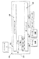
図1は、本発明の一実施例を示すブロック図である。ポートルータ100は、コントローラスイッチ120、ポートスイッチ140、及びコントローラスイッチ120とポートスイッチ140との間の接続200を具えている。接続200はハブ素子201を具えている。ポートルータ100は、ポートA〜Dを、単一のコントローラであるコントローラAに接続している。コントローラスイッチ120、ポートスイッチ140、及び接続200の各々は、特定の入力及び出力の能力を有する。ポートスイッチ140は、各々がインタフェースポートに接続された固定の入力141〜144を有する。ポートスイッチ140は、あらゆるポートから1つ以上のスイッチ出力へのルーティング(経路設定)をするものである。ポートスイッチ140は、すべてのルーティング素子をサポートするための合計数の出力を有する。図1の例では、ポートスイッチ140はハブ素子201用の4つの出力を有する。これらのハブ素子は、所定の機器用のIOインタフェースの要求に追従することが好ましい。各ハブ素子は、その入力どうしを組合わせて、コントローラスイッチに入力される単一の出力を供給する。一部のIOインタフェースは、ハブ素子201のことを、ブリッジ、コンセントレータ(集信装置)、あるいは物理インタフェースと称する。多数のハブ素子を用いて、ポートスイッチ140をコントローラスイッチ120に接続することができる。
【0012】
コントローラスイッチ120は、ハブ素子への接続毎に1つの入力を有し、かつポートスイッチ140への直接接続(図2〜図4に示す)毎に1つの入力を有することが好ましい。コントローラスイッチ120からの出力は、所定の機器において必要か、あるいは利用可能なコントローラの数に整合すべく固定されている。図1に示すように、コントローラスイッチは、ハブ素子201に接続した1つの入力121、及びコントローラAに接続した1つの出力127を有する。
【0013】
図2に、ポートDへの新たな装置の追加を示し、ここではコントローラAについての帯域幅の能力がしきい値に達している。装置をポートDに挿入すると、この装置が検出されて装置の能力要求が報告される。この能力は、コントローラAの有効能力より大きいものと計算される。新たなコントローラBをシステムに追加して、ポートルータ100を再構成して、ポートA、B、及びCの、コントローラAへの接続を行い、ポートDのみをコントローラBに接続する。ポートDのハブ素子201への接続を解除して、ポートスイッチ140とコントローラスイッチ120の間に新たな接続を設定する。コントローラBへの接続は、コントローラスイッチの出力128から設定する。ポートDから新たな装置への、及び新たな装置からポートDへのすべてのデータフローが、この新たな接続を通って、ポートスイッチの出力149からコントローラスイッチの入力122に流れる。ポートA、B、及びCからのすべてのデータフローは、ポートスイッチの出力145、146からハブ素子201への同じルーティングを有し続ける。この構成では、ポートA、B、及びCからのデータフローを組み合わせて、コントローラスイッチの入力121に送達する。
【0014】
図3に、インタフェースポートCに接続された他の装置の追加、コントローラCの追加、ハブ素子201の接続の解除、及び他の直接接続203を追加を示す。ポートCに装置を挿入すると、この装置が検出されて、装置の能力要求が報告される。この能力は専用コントローラを必要とするものとして計算される。コントローラCを設定して、システムに追加する。ポートAとポートBのコントローラAへの接続、ポートCのコントローラCへの接続、及びポートDのコントローラBへの接続を行うべく、ポートルータ100を再構成する。ポートCのハブ素子201への接続を解除して、ポートスイッチ140とコントローラスイッチ120との間に新たな直接接続203を設定する。コントローラスイッチの出力129からコントローラCへの接続を設定する。ポートCから最も新規の装置への、及び最も新規の装置からポートCへのすべてのデータフローは、この新たな接続を通って、ポートスイッチの出力150からコントローラスイッチの入力123に流れる。ポートA及びポートBからのデータフローは、ポートスイッチの出力145及び146からハブ素子201への同じルーティングを有し続ける。ポートDからのデータフローは、ポートスイッチの出力150から接続203を通ってコントローラスイッチの入力123へ、そしてコントローラスイッチの出力128を通ってコントローラBへ、となり続ける。この構成では、ポートA及びポートBからのデータフローがハブ素子201内で組み合わされて、コントローラスイッチの入力121に送達される。
【0015】
図4に、4つのポート及び4つのコントローラのポートルータの構成についての、合計接続数を示す。ありうる接続のすべてを示すが、図1〜図3に示すように、所望のトポロジに応じた所定の接続のみが作用している。トポロジは、有効なデータフローのために最適化されていることが好ましい。ポートスイッチ140は、存在するポート毎に単一の入力を有する(即ち4つのポートは4つの入力を必要とし、5つのポートは5つの入力を必要とする、等)ことが好ましい。ポートスイッチ140は、コントローラスイッチ120に直接接続するために、ポート毎に1つの4つの出力接続149〜152を有し、これらは接続202、203、204、及び205で表わす。ハブ素子の数は変化しうるものであり、図4に示すものは2つである。ハブ素子206はポートスイッチの出力145〜148、及びコントローラスイッチの入力121に接続されている。ハブ素子206はポートスイッチの出力153〜156、及びコントローラスイッチの入力126に接続されている。コントローラスイッチは、システム内に存在しうるコントローラ毎に1つの出力を有する。システム内のコントローラの数は変化しうる。コントローラの数はサポートするポートの数以下であることが好ましく、本実施例では4つである。コントローラスイッチの出力127〜130は、コントローラA〜D毎の入力に接続されている。
【0016】
動作中には、所定のポートが所望のコントローラに接続されたデフォルト状態で、ポートスイッチ100が始動することが好ましい。図1の例には、4つのポート、ポートA及びポートBに接続された2つの装置、1つのハブ素子201、及びコントローラAがあるデフォルト状態を有するシステムを示す。好適にはポートルータ100内に存在する一組のハードウエアレジスタ(図示せず)を通して、システム内で動作するソフトウエアがポートルータ100に問い合わせをして、デフォルトのトポロジを見出すことができる。システムソフトウエアは、前記ハードウエアレジスタに値をプログラムすることによって、ポートの任意の組合わせとコントローラとの間の信号のルーティングの変更を実行することができる。動作中に事象が発生する。事象は、新たな装置が除去されるか、あるいはポートに挿入されることである。この事象は前記ソフトウエアをトリガして、この新たなデバイスの要求を検査する。これらの要求には、装置のデータ能力の要求(帯域幅及びレイテンシ(呼出し時間))、及びそのデータ形式(非同期、等時性、バースト(突発的)、ストリーム(流れ))を含めることができる。これらの新たな要求を、既に設置されている装置からの、現在の一まとまりの要求と組み合わせて、ポートからのルーティングをするための最適なトポロジを算出する。システムソフトウエアがIO動作を中断して、ポートとIOコントローラとの間の再ルーティングを実行することが好ましい。次にシステムソフトウエアがIO動作を再開して、新たな事象が発生するまでは、この最適化したルーティングが新たなルーティングとなる。
【0017】
本発明の他の実施例では、ポートルータ100が、システムソフトウエアの調停を必要とせずに、ルーティング及び再ルーティングを内部的に実行できるような、埋め込み型のソフトウエアを具えていることが好ましい。これにより、ポートルータ100を通るデータの流れにもとづく、自己監視及び動的な負荷平衡の能力が提供される。
【0018】
このように、本発明の一実施例によるポートルータは、1つ以上の入力及び1つ以上の出力を有するコントローラスイッチ120と、1つ以上の入力及び1つ以上の出力を有するポートスイッチ140と、コントローラスイッチ120とポートスイッチ140との間の1つ以上の接続とを具えている。コントローラスイッチ120、ポートスイッチ140、及び1つ以上の接続200は、ポートスイッチの入力とコントローラスイッチの出力との間の動的な再ルーティングを行うべく適応されている。
【0019】
コントローラスイッチ120、ポートスイッチ140、及び1つ以上の接続200は、変化する負荷要求にもとづいて動的な負荷平衡を行うべく、動的に構成することができる。1つ以上の接続200は、1つ以上のハブ素子201、206を具え、さらにコントローラスイッチ120とポートスイッチ140との間の1つ以上の直接接続を任意に具えていることが好ましい。1つ以上のハブ素子201、206は、ポートスイッチ140からの出力を1つ以上受信して、コントローラスイッチ120に1つの入力を供給すべく適応されていることが好ましい。ポートスイッチの入力は、各々がインタフェースポートに接続されていることが好ましく、ポートスイッチ140は、1つ以上のインタフェースポートから、ポートスイッチの出力の1つ以上へのルーティングをすべく適応されていることが好ましい。コントローラスイッチ120はさらに、ポートスイッチ140への直接接続毎の1つの入力と、1つ以上のハブ素子201、206への接続毎の1つの入力とを具えている。コントローラスイッチ120からの1つ以上の出力の各々が、対応するコントローラに接続されていることが好ましい。コントローラスイッチ120及びポートスイッチ140はクロスバースイッチを具えていることが好ましい。
【0020】
本発明の他の要点は、各々が対応する1つ以上のインタフェースポートに接続された1つ以上の入力を有するポートスイッチ140と、コントローラスイッチ120と、ポートスイッチ140とコントローラスイッチ120との間の1つ以上の接続200とを具えた集積回路である。コントローラスイッチ120、ポートスイッチ140、及び1つ以上の接続200が協働して、1つ以上のインタフェースポートと演算装置の内部回路との間の接続を動的に再ルーティングすべく適応された構成可能なスイッチを提供する。
【0021】
1つ以上の接続200は、1つ以上のハブ素子を具え、さらにコントローラスイッチ120とポートスイッチ140との間の1つ以上の直接接続を任意に具えていることが好ましい。
【0022】
本発明の他の要点は、ポートから演算プラットフォームの内部回路への動的なルーティングをする方法であり、この方法は、構成可能なスイッチング回路を用意するステップと、この構成可能なスイッチング回路に問い合わせをして、デフォルトのトポロジを決定するステップと、構成可能なスイッチング回路を通るデータフローの変化の発生により、最適化したトポロジを算出するステップと、動作を中断して、最適化したトポロジにもとづいて、インタフェースポートと前記内部回路との間の再ルーティングを実行するステップと、構成可能なスイッチング回路を通るIO動作を再開するステップとを具えている。
【0023】
前記最適化したトポロジは、前記再構成可能なスイッチ回路を通るデータの流れにもとづいて、動的な負荷平衡を行うことが好ましい。前記構成可能なスイッチング回路を通るデータフローの変化には、前記ポートスイッチの入力または前記インタフェースポートに装置を動作的に接続するか、あるいはこれらの入力またはポートから装置を解放することを含めることができる。
【0024】
本発明は、好適な実施例について図面を参照して説明してきたが、本発明はこうした実施例に限定されるものではなく、当業者が本発明の範疇を逸脱することなく、種々の変更及び変形を行いうることは明らかである。
【図面の簡単な説明】
【図1】 本発明の一実施例を示すブロック図である。
【図2】 本発明の他の実施例を示すブロック図である。
【図3】 本発明の他の実施例を示すブロック図である。
【図4】 本発明の他の実施例を示すブロック図である。[0001]
(Field of Invention)
The present invention relates to a semiconductor device, and more particularly to a port router.
[0002]
(Background of the Invention)
Existing computing platforms provide a mechanism for attaching external devices to a computer and performing input / output (IO) between the computing platform and a port connecting the external devices. Conventional methods employ a fixed connection between the port and the IO controller that resides inside the computing platform. This technique of providing a fixed routing mechanism allows the system to adapt to change requests such as adding new devices or introducing devices that require the full capabilities of a single IO controller. It limits the ability to do.
[0003]
An environment in which a large number of IO controllers can be used in a single device or in a system is increasing. Information devices, set-top boxes, cable modems, game consoles, intelligent devices, handheld computers, palm-sized computers, embedded control systems, workstations, servers, and the like have multiple IO controllers. Currently available technologies do not provide a mechanism for dynamic rerouting between ports and IO controllers. Therefore, it is desirable to be able to dynamically change routing when adding new devices or introducing devices that require the full capabilities of a single IO controller. There is a need for a mechanism for dynamically connecting physical connections (ports) to IO controllers that reside within the computing platform.
[0004]
(Summary of Invention)
In one aspect of the invention, there is provided a port router with controller switches, port switches, and one or more connections between these controller switches and port switches. These controller switches, port switches, and one or more connections are adapted to provide dynamic rerouting between port switch inputs and controller switch outputs.
[0005]
Another aspect of the present invention is to provide a method for dynamic routing from ports to internal circuitry of the computing platform. The method comprises the steps of providing a configurable switching circuit, querying the configurable switching circuit to determine a default topology, and generating a change in data flow through the configurable switching circuit. Calculating the optimal topology, interrupting the operation based on the optimal topology, and performing rerouting between the interface port and the internal circuit, and the IO operation through the configurable switching circuit. And resuming the steps.
[0006]
The present invention can be used in personal computer systems and other types including information equipment, set top boxes, cable modems, game consoles, intelligent equipment, handheld computers, palm size computers, embedded control systems, workstations, etc. However, the present invention is not limited to these.
[0007]
(Detailed description of examples)
The present invention provides a configurable switching circuit that dynamically creates connections between ports and internal circuitry to allow rerouting. One embodiment of the present invention provides a device for dynamic routing from between physical connections (ports) to one or more IO controllers residing within a computing platform. One advantage of the present invention is that the number of IO devices (such as causing a change in the optimal data flow topology) or by rerouting from the port so that a new topology is established. The ability to adapt to changing requirements. This ability to provide adaptive routing allows a system or device that cannot operate in a competitive environment to dedicate bandwidth resources. Other advantages of the present invention include the ability to use a port router as a blocking mechanism to allow certain IO ports to be isolated from the system. This is particularly useful when the device malfunctions or the device is causing a system malfunction.
[0008]
The IO controller provides the system software with a mechanism for sending and receiving data. The port provides a mounting mechanism for connecting the device to the computing system. For the next generation, a computing platform having a large number of IO controllers in a single device or system becomes available. Conventional hardware wiring routing mechanisms limit the ability of the system to adapt to changing demands. The present invention avoids these limitations and allows for dynamic routing and rerouting when new devices are added to the system or when devices that require the full capabilities of a single IO controller are introduced. It provides a routing mechanism to do so. The present invention further provides a mechanism for dynamically load balancing data from device to device among multiple IO controllers that may exist within a computing platform.
[0009]
The present invention can be used in personal computer systems, but in other types of computer platforms including information equipment, set-top boxes, cable modems, game consoles, intelligent equipment, handheld computers, palm-sized computers, embedded control systems. Can also be applied, but is not limited thereto.
[0010]
Embodiments of the present invention will be described below with reference to the drawings.
The representation of FIGS. 1-4 is for illustrative purposes only and should not limit the possible implementation of the invention. 1-4, which schematically illustrate selected embodiments of the present invention,
[0011]
FIG. 1 is a block diagram showing an embodiment of the present invention. The
[0012]
The
[0013]
FIG. 2 shows the addition of a new device to port D, where the bandwidth capability for controller A has reached a threshold. When a device is inserted into port D, the device is detected and a device capability request is reported. This capacity is calculated to be greater than the effective capacity of controller A. A new controller B is added to the system, the
[0014]
3 shows the addition of another device connected to the interface port C, the addition of the controller C, the disconnection of the
[0015]
FIG. 4 shows the total number of connections for the configuration of the port router of four ports and four controllers. Although all possible connections are shown, only predetermined connections according to the desired topology are working as shown in FIGS. The topology is preferably optimized for effective data flow. The
[0016]
During operation, the
[0017]
In another embodiment of the present invention, the
[0018]
Thus, a port router according to one embodiment of the present invention includes a
[0019]
[0020]
Another aspect of the present invention is that there is a
[0021]
The one or
[0022]
Another aspect of the invention is a method for dynamic routing from a port to an internal circuit of a computing platform, the method comprising providing a configurable switching circuit and interrogating the configurable switching circuit. To determine a default topology, to calculate an optimized topology by the occurrence of a change in data flow through the configurable switching circuit, and to interrupt the operation and based on the optimized topology Performing rerouting between the interface port and the internal circuit and resuming IO operation through the configurable switching circuit.
[0023]
The optimized topology preferably performs dynamic load balancing based on the flow of data through the reconfigurable switch circuit. Changes in data flow through the configurable switching circuit may include operably connecting devices to the port switch inputs or the interface ports, or releasing devices from these inputs or ports. it can.
[0024]
Although the present invention has been described with reference to the preferred embodiments with reference to the drawings, the present invention is not limited to these embodiments, and various modifications and changes can be made by those skilled in the art without departing from the scope of the present invention. It is clear that deformations can be made.
[Brief description of the drawings]
FIG. 1 is a block diagram showing an embodiment of the present invention.
FIG. 2 is a block diagram showing another embodiment of the present invention.
FIG. 3 is a block diagram showing another embodiment of the present invention.
FIG. 4 is a block diagram showing another embodiment of the present invention.
Claims (10)
1つ以上の入力及び1つ以上の出力を有する動的なコントローラスイッチ;
1つ以上の入力及び1つ以上の出力を有する静的なポートスイッチ;及び
前記コントローラスイッチと前記ポートスイッチとの間の、1つ以上のハブ素子及び選択的に直接接続を含む接続
を具え、
前記コントローラスイッチ、前記ポートスイッチ、及び前記コントローラスイッチと前記ポートスイッチの間の前記接続が、前記1つ以上のハブ素子及び/又は前記1つ以上の直接接続を除去及び/又は挿入することによって、前記ポートスイッチの入力と前記コントローラスイッチの出力との間の接続の動的な再ルーティングを行うべく構成されていることを特徴とするポートルータ。 A port router,
A dynamic controller switch having one or more inputs and one or more outputs;
A static port switch having one or more inputs and one or more outputs; and a connection comprising one or more hub elements and optionally a direct connection between the controller switch and the port switch;
The controller switch, the port switch, and the connection between the controller switch and the port switch by removing and / or inserting the one or more hub elements and / or the one or more direct connections; A port router configured to dynamically reroute a connection between an input of the port switch and an output of the controller switch.
各々が1つ以上の対応するインタフェースポートに接続された1つ以上の入力を有する静的なポートスイッチ;
動的なコントローラスイッチ;及び
前記ポートスイッチと前記コントローラスイッチとの間の、1つ以上のハブ素子及び選択的に直接接続を含む接続
を具え、
前記コントローラスイッチ、前記ポートスイッチ、及び前記コントローラスイッチと前記ポートスイッチの間の前記接続が協働して、前記1つ以上のハブ素子及び/又は前記1つ以上の直接接続を除去及び/又は挿入することによって、前記1つ以上のインタフェースポートと演算装置の内部回路との間の接続を動的に再ルーティングすべく構成された構成可能なスイッチを提供することを特徴とする集積回路。 An integrated circuit,
A static port switch having one or more inputs each connected to one or more corresponding interface ports;
A dynamic controller switch; and a connection between the port switch and the controller switch , including one or more hub elements and optionally a direct connection ;
The controller switch, the port switch, and the connection between the controller switch and the port switch cooperate to remove and / or insert the one or more hub elements and / or the one or more direct connections. by an integrated circuit and providing a dynamically configured switch capable configured to reroute the connection between the internal circuit of said one or more interface ports and the arithmetic unit.
1つ以上のハブ素子及び選択的に直接接続を含む構成可能なスイッチング回路を用意するステップ;
前記構成可能なスイッチング回路に問い合わせをしてデフォルトのトポロジを決定するステップ;
前記構成可能なスイッチング回路を通るデータフローの変化の発生により、所望のトポロジを演算するステップ;
動作を中断して、前記1つ以上のハブ素子及び/又は前記1つ以上の直接接続を除去及び/又は挿入することによって、前記所望のトポロジに基づいて前記インタフェースポートと前記内部回路との間の再ルーティングを実行するステップ;及び
前記構成可能なスイッチング回路を通るIO動作を再開するステップ
を具える方法。A method for dynamic routing from a port to the internal circuitry of a computing platform,
Providing a configurable switching circuit including one or more hub elements and optionally direct connections ;
Interrogating the configurable switching circuit to determine a default topology;
Computing a desired topology by the occurrence of a change in data flow through the configurable switching circuit;
And interrupting the operation, the by one or more connection hub element and / or said one or more direct removal and / or insertion, and the interface ports and the internal circuit based on the desired topology Performing rerouting between; and resuming IO operations through the configurable switching circuit.
Applications Claiming Priority (9)
| Application Number | Priority Date | Filing Date | Title |
|---|---|---|---|
| US11477299P | 1999-01-05 | 1999-01-05 | |
| US11477199P | 1999-01-05 | 1999-01-05 | |
| US60/114,772 | 1999-01-05 | ||
| US60/114,771 | 1999-01-05 | ||
| US11476799P | 1999-01-06 | 1999-01-06 | |
| US60/114,767 | 1999-01-06 | ||
| US09/477,593 US6324613B1 (en) | 1999-01-05 | 2000-01-04 | Port router |
| US09/477,593 | 2000-01-04 | ||
| PCT/US2000/000176 WO2000041082A2 (en) | 1999-01-05 | 2000-01-05 | Port router |
Publications (3)
| Publication Number | Publication Date |
|---|---|
| JP2003526830A JP2003526830A (en) | 2003-09-09 |
| JP2003526830A5 JP2003526830A5 (en) | 2007-03-15 |
| JP4491765B2 true JP4491765B2 (en) | 2010-06-30 |
Family
ID=27493971
Family Applications (1)
| Application Number | Title | Priority Date | Filing Date |
|---|---|---|---|
| JP2000592740A Expired - Fee Related JP4491765B2 (en) | 1999-01-05 | 2000-01-05 | Port router |
Country Status (4)
| Country | Link |
|---|---|
| US (1) | US6324613B1 (en) |
| JP (1) | JP4491765B2 (en) |
| GB (1) | GB2361610B (en) |
| WO (1) | WO2000041082A2 (en) |
Families Citing this family (22)
| Publication number | Priority date | Publication date | Assignee | Title |
|---|---|---|---|---|
| US6901517B1 (en) * | 1999-07-16 | 2005-05-31 | Marconi Communications, Inc. | Hardware based security groups, firewall load sharing, and firewall redundancy |
| US6801971B1 (en) * | 1999-09-10 | 2004-10-05 | Agere Systems Inc. | Method and system for shared bus access |
| US6519660B1 (en) * | 1999-09-28 | 2003-02-11 | International Business Machines Corporation | Method, system and program products for determining I/O configuration entropy |
| US7568052B1 (en) * | 1999-09-28 | 2009-07-28 | International Business Machines Corporation | Method, system and program products for managing I/O configurations of a computing environment |
| US6986137B1 (en) * | 1999-09-28 | 2006-01-10 | International Business Machines Corporation | Method, system and program products for managing logical processors of a computing environment |
| US6598088B1 (en) * | 1999-12-30 | 2003-07-22 | Nortel Networks Corporation | Port switch |
| CN1173280C (en) * | 2000-10-26 | 2004-10-27 | 上海奇码数字信息有限公司 | Adaptive information processing system and with network topology |
| US6839793B2 (en) * | 2001-03-28 | 2005-01-04 | Intel Corporation | Method and apparatus to maximize bandwidth availability to USB devices |
| US6898202B2 (en) * | 2001-06-27 | 2005-05-24 | International Business Machines Corporation | Method, apparatus and computer program for informing a requesting device of port configuration changes in a computer network switching device |
| US20030135291A1 (en) * | 2002-01-11 | 2003-07-17 | Delano Eric R. | Customized ports in a crossbar and method for transmitting data between customized ports and system agents |
| US7852836B2 (en) * | 2003-11-19 | 2010-12-14 | Cray Inc. | Reduced arbitration routing system and method |
| US7058738B2 (en) * | 2004-04-28 | 2006-06-06 | Microsoft Corporation | Configurable PCI express switch which allows multiple CPUs to be connected to multiple I/O devices |
| US20060020720A1 (en) * | 2004-07-23 | 2006-01-26 | Lsi Logic Corporation | Multi-controller IO shipping |
| JP4509827B2 (en) * | 2005-03-04 | 2010-07-21 | 富士通株式会社 | Computer system using serial connect bus and method of connecting multiple CPU units by serial connect bus |
| JP4711709B2 (en) * | 2005-03-18 | 2011-06-29 | 富士通株式会社 | Partition allocation method and computer system |
| JP4673712B2 (en) * | 2005-09-28 | 2011-04-20 | 富士通株式会社 | Network configuration apparatus and network configuration method |
| US20070183337A1 (en) * | 2006-02-03 | 2007-08-09 | International Business Machines Corporation | FC-AL cabling management system |
| US7984228B2 (en) * | 2006-02-28 | 2011-07-19 | Microsoft Corporation | Device connection routing for controller |
| EP2073598B1 (en) * | 2007-12-21 | 2017-10-04 | Telefonaktiebolaget LM Ericsson (publ) | Technique for providing network access to different entities |
| US10938751B2 (en) * | 2018-04-18 | 2021-03-02 | Hewlett Packard Enterprise Development Lp | Hierarchical switching devices |
| US10757038B2 (en) | 2018-07-06 | 2020-08-25 | Hewlett Packard Enterprise Development Lp | Reservation-based switching devices |
| US11855913B2 (en) | 2018-10-31 | 2023-12-26 | Hewlett Packard Enterprise Development Lp | Hierarchical switching device with deadlockable storage and storage partitions |
Family Cites Families (21)
| Publication number | Priority date | Publication date | Assignee | Title |
|---|---|---|---|---|
| US3581286A (en) * | 1969-01-13 | 1971-05-25 | Ibm | Module switching apparatus with status sensing and dynamic sharing of modules |
| JPS63211060A (en) * | 1987-02-27 | 1988-09-01 | Nippon Telegr & Teleph Corp <Ntt> | Load distribution control system for multiprocessor system |
| JPH01175453A (en) | 1987-12-25 | 1989-07-11 | American Teleph & Telegr Co <Att> | Electric source with stable output voltage |
| US5107489A (en) * | 1989-10-30 | 1992-04-21 | Brown Paul J | Switch and its protocol for making dynamic connections |
| AU650242B2 (en) * | 1989-11-28 | 1994-06-16 | International Business Machines Corporation | Methods and apparatus for dynamically managing input/output (I/O) connectivity |
| JPH0756644B2 (en) * | 1990-08-31 | 1995-06-14 | インターナショナル・ビジネス・マシーンズ・コーポレイション | Status change notification device and method |
| GB2258581B (en) * | 1991-08-02 | 1995-03-29 | Plessey Telecomm | An ATM switching arrangement |
| JP3168681B2 (en) * | 1992-04-22 | 2001-05-21 | 株式会社日立製作所 | Data transmission method and system for concentrator network |
| GB2273224B (en) * | 1992-12-05 | 1997-01-22 | Netcomm Ltd | An ATM Cell switch suitable for multicast switching |
| JP3110583B2 (en) * | 1993-05-25 | 2000-11-20 | 三菱電機株式会社 | Router device |
| JP2637918B2 (en) * | 1993-10-15 | 1997-08-06 | インターナショナル・ビジネス・マシーンズ・コーポレイション | Method and apparatus for conflict resolution of cascade switch |
| US5530813A (en) | 1994-08-04 | 1996-06-25 | Pattern Processing Technology | Field-programmable electronic crossbar system and method for using same |
| JPH08249254A (en) * | 1995-03-15 | 1996-09-27 | Mitsubishi Electric Corp | Multicomputer system |
| US5892766A (en) * | 1996-02-22 | 1999-04-06 | Fujitsu, Ltd. | Method and apparatus for coordinating access to an output of a routing device in a packet switching network |
| JP3533859B2 (en) * | 1996-12-24 | 2004-05-31 | 松下電工株式会社 | Distributed integrated wiring system |
| US5734649A (en) * | 1996-05-31 | 1998-03-31 | Bbn Corporation | Data packet router |
| JP2944531B2 (en) * | 1996-09-12 | 1999-09-06 | 日本電気通信システム株式会社 | LAN connection device |
| US5909547A (en) * | 1996-10-24 | 1999-06-01 | Lucent Technologies Inc. | Method for shared memory management in network nodes |
| US5922077A (en) * | 1996-11-14 | 1999-07-13 | Data General Corporation | Fail-over switching system |
| US6289021B1 (en) * | 1997-01-24 | 2001-09-11 | Interactic Holdings, Llc | Scaleable low-latency switch for usage in an interconnect structure |
| US6035366A (en) * | 1997-03-07 | 2000-03-07 | Advanced Micro Devices Inc | Computer architecture using packet switches for internal data transfer |
-
2000
- 2000-01-04 US US09/477,593 patent/US6324613B1/en not_active Expired - Lifetime
- 2000-01-05 WO PCT/US2000/000176 patent/WO2000041082A2/en active Search and Examination
- 2000-01-05 JP JP2000592740A patent/JP4491765B2/en not_active Expired - Fee Related
- 2000-01-05 GB GB0114868A patent/GB2361610B/en not_active Expired - Fee Related
Also Published As
| Publication number | Publication date |
|---|---|
| WO2000041082A3 (en) | 2000-11-30 |
| JP2003526830A (en) | 2003-09-09 |
| GB2361610A (en) | 2001-10-24 |
| WO2000041082A2 (en) | 2000-07-13 |
| US6324613B1 (en) | 2001-11-27 |
| GB0114868D0 (en) | 2001-08-08 |
| GB2361610B (en) | 2004-02-25 |
Similar Documents
| Publication | Publication Date | Title |
|---|---|---|
| JP4491765B2 (en) | Port router | |
| JP4606589B2 (en) | Apparatus and method for dynamically reconfiguring input / output devices | |
| US6600739B1 (en) | Method and apparatus for switching among a plurality of universal serial bus host devices | |
| EP1687716B1 (en) | Method, system, and program for interfacing with a network adaptor supporting a plurality of devices | |
| US6308239B1 (en) | Interface switching apparatus and switching control method | |
| US7370224B1 (en) | System and method for enabling redundancy in PCI-Express architecture | |
| JP2019153300A (en) | SYSTEM AND METHOD FOR SUPPORTING MULTI-MODE AND/OR MULTI-SPEED NVMe-oF DEVICES | |
| KR20000006576A (en) | System and method for facilitating the sharing of resources such as storage subsystems among a plurality of host computers in a digital data processing system | |
| US7539129B2 (en) | Server, method for controlling data communication of server, computer product | |
| US7706259B2 (en) | Method for implementing redundant structure of ATCA (advanced telecom computing architecture) system via base interface and the ATCA system for use in the same | |
| US7702717B2 (en) | Method and apparatus for controlling management agents in a computer system on a packet-switched input/output network | |
| US6871294B2 (en) | Dynamically reconfigurable interconnection | |
| JP3988146B2 (en) | Multi-node system, inter-node crossbar switch, node, switch program and node program | |
| KR100936203B1 (en) | Data processing management apparatus, mode management apparatus and mode management method | |
| US5544330A (en) | Fault tolerant interconnect topology using multiple rings | |
| JP2002504793A (en) | Virtual connection protection switching | |
| EP1540473B1 (en) | System and method for network interfacing in a multiple network environment | |
| JP2003178045A (en) | System domain targeted configurable interconnection | |
| US6564277B1 (en) | Method and system for handling interrupts in a node controller without attached processors | |
| CN112463670A (en) | Storage controller access method and related device | |
| JP4089506B2 (en) | File sharing system, server and program | |
| US6801498B1 (en) | Asynchronous transfer mode communication equipment and method for switching virtual path of same | |
| JPS5878221A (en) | Bus controlling system | |
| JP2002207544A (en) | Concurrent operating system personal computer | |
| JPH0247752A (en) | Channel switching system |
Legal Events
| Date | Code | Title | Description |
|---|---|---|---|
| A521 | Written amendment |
Free format text: JAPANESE INTERMEDIATE CODE: A523 Effective date: 20061205 |
|
| A621 | Written request for application examination |
Free format text: JAPANESE INTERMEDIATE CODE: A621 Effective date: 20061205 |
|
| A521 | Written amendment |
Free format text: JAPANESE INTERMEDIATE CODE: A523 Effective date: 20070124 |
|
| RD03 | Notification of appointment of power of attorney |
Free format text: JAPANESE INTERMEDIATE CODE: A7423 Effective date: 20080708 |
|
| RD04 | Notification of resignation of power of attorney |
Free format text: JAPANESE INTERMEDIATE CODE: A7424 Effective date: 20080709 |
|
| A131 | Notification of reasons for refusal |
Free format text: JAPANESE INTERMEDIATE CODE: A131 Effective date: 20091116 |
|
| A521 | Written amendment |
Free format text: JAPANESE INTERMEDIATE CODE: A523 Effective date: 20100129 |
|
| TRDD | Decision of grant or rejection written | ||
| A01 | Written decision to grant a patent or to grant a registration (utility model) |
Free format text: JAPANESE INTERMEDIATE CODE: A01 Effective date: 20100301 |
|
| A01 | Written decision to grant a patent or to grant a registration (utility model) |
Free format text: JAPANESE INTERMEDIATE CODE: A01 |
|
| A711 | Notification of change in applicant |
Free format text: JAPANESE INTERMEDIATE CODE: A712 Effective date: 20100325 |
|
| A61 | First payment of annual fees (during grant procedure) |
Free format text: JAPANESE INTERMEDIATE CODE: A61 Effective date: 20100325 |
|
| R150 | Certificate of patent or registration of utility model |
Free format text: JAPANESE INTERMEDIATE CODE: R150 |
|
| FPAY | Renewal fee payment (event date is renewal date of database) |
Free format text: PAYMENT UNTIL: 20130416 Year of fee payment: 3 |
|
| FPAY | Renewal fee payment (event date is renewal date of database) |
Free format text: PAYMENT UNTIL: 20130416 Year of fee payment: 3 |
|
| FPAY | Renewal fee payment (event date is renewal date of database) |
Free format text: PAYMENT UNTIL: 20140416 Year of fee payment: 4 |
|
| R250 | Receipt of annual fees |
Free format text: JAPANESE INTERMEDIATE CODE: R250 |
|
| R250 | Receipt of annual fees |
Free format text: JAPANESE INTERMEDIATE CODE: R250 |
|
| S111 | Request for change of ownership or part of ownership |
Free format text: JAPANESE INTERMEDIATE CODE: R313113 |
|
| S533 | Written request for registration of change of name |
Free format text: JAPANESE INTERMEDIATE CODE: R313533 |
|
| R350 | Written notification of registration of transfer |
Free format text: JAPANESE INTERMEDIATE CODE: R350 |
|
| R250 | Receipt of annual fees |
Free format text: JAPANESE INTERMEDIATE CODE: R250 |
|
| R250 | Receipt of annual fees |
Free format text: JAPANESE INTERMEDIATE CODE: R250 |
|
| LAPS | Cancellation because of no payment of annual fees |