JP4490908B2 - Wastewater treatment equipment - Google Patents
Wastewater treatment equipment Download PDFInfo
- Publication number
- JP4490908B2 JP4490908B2 JP2005366696A JP2005366696A JP4490908B2 JP 4490908 B2 JP4490908 B2 JP 4490908B2 JP 2005366696 A JP2005366696 A JP 2005366696A JP 2005366696 A JP2005366696 A JP 2005366696A JP 4490908 B2 JP4490908 B2 JP 4490908B2
- Authority
- JP
- Japan
- Prior art keywords
- tank
- sludge
- wastewater treatment
- concentration
- wastewater
- Prior art date
- Legal status (The legal status is an assumption and is not a legal conclusion. Google has not performed a legal analysis and makes no representation as to the accuracy of the status listed.)
- Expired - Fee Related
Links
Images


Classifications
-
- Y—GENERAL TAGGING OF NEW TECHNOLOGICAL DEVELOPMENTS; GENERAL TAGGING OF CROSS-SECTIONAL TECHNOLOGIES SPANNING OVER SEVERAL SECTIONS OF THE IPC; TECHNICAL SUBJECTS COVERED BY FORMER USPC CROSS-REFERENCE ART COLLECTIONS [XRACs] AND DIGESTS
- Y02—TECHNOLOGIES OR APPLICATIONS FOR MITIGATION OR ADAPTATION AGAINST CLIMATE CHANGE
- Y02A—TECHNOLOGIES FOR ADAPTATION TO CLIMATE CHANGE
- Y02A50/00—TECHNOLOGIES FOR ADAPTATION TO CLIMATE CHANGE in human health protection, e.g. against extreme weather
- Y02A50/20—Air quality improvement or preservation, e.g. vehicle emission control or emission reduction by using catalytic converters
-
- Y—GENERAL TAGGING OF NEW TECHNOLOGICAL DEVELOPMENTS; GENERAL TAGGING OF CROSS-SECTIONAL TECHNOLOGIES SPANNING OVER SEVERAL SECTIONS OF THE IPC; TECHNICAL SUBJECTS COVERED BY FORMER USPC CROSS-REFERENCE ART COLLECTIONS [XRACs] AND DIGESTS
- Y02—TECHNOLOGIES OR APPLICATIONS FOR MITIGATION OR ADAPTATION AGAINST CLIMATE CHANGE
- Y02W—CLIMATE CHANGE MITIGATION TECHNOLOGIES RELATED TO WASTEWATER TREATMENT OR WASTE MANAGEMENT
- Y02W10/00—Technologies for wastewater treatment
- Y02W10/10—Biological treatment of water, waste water, or sewage
Landscapes
- Purification Treatments By Anaerobic Or Anaerobic And Aerobic Bacteria Or Animals (AREA)
- Treating Waste Gases (AREA)
- Biological Treatment Of Waste Water (AREA)
Description
この発明は、排水処理装置に関する。一例として、この発明は、2004年4月から施行された水質汚濁防止法の一部改正による窒素の総量規制および2001年4月から施行されたPRTR(Pollutant Release and Transfer Register)法による有害物質の排出量削減に対応する排水処理装置に関する。この発明は、例えば、主として半導体工場から排水されるアミノエタノールとジメチルスルホキシド含有排水と高濃度窒素排水(高濃度アンモニア排水、現像廃液およびジメチルホルムアミド廃液等)の2系統の排水を処理する排水処理装置に関する。アミノエタノールはPRTR法の第1種指定化学物質に指定されている。また、この発明は、一例として、悪臭処理ができ、かつ無希釈で微生物処理できるイニシャルコスト、ランニングコストおよびメンテナンスコストに優れた排水処理装置に関する。
This invention relates to wastewater treatment apparatus. As an example, the present invention relates to the regulation of the total amount of nitrogen by partial amendment of the Water Pollution Control Law, which came into effect from April 2004, and the use of harmful substances by the PRTR (Pollutant Release and Transfer Registry) Law, which came into effect from April 2001. about wastewater treatment apparatus that corresponds to the emission reduction. The present invention, for example, wastewater that processes mainly aminoethanol and dimethyl sulfoxide containing waste water and the high concentration nitrogen wastewater discharged from the semiconductor plant wastewater of two systems (high strength ammonia wastewater, waste developer and dimethylformamide waste liquid) The present invention relates to a processing apparatus. Aminoethanol is designated as a
従来、アミノエタノールとジメチルスルホキシドとを含有した排水、具体的一例としては、3000ppm程度の高濃度アミノエタノールとジメチルスルホキシドを含有した排水は、アミノエタノールの微生物毒性が高いので、一般的には、微生物処理できなかった。 Conventionally, wastewater containing aminoethanol and dimethylsulfoxide, for example, wastewater containing high-concentration aminoethanol and dimethylsulfoxide of about 3000 ppm is highly microbially toxic to aminoethanol. Could not process.
アミノエタノールとジメチルスルホキシドとを含有した排水が微生物処理されているケースは、アミノエタノールとジメチルスルホキシドの濃度がそれぞれ数百ppmと低い濃度での処理が一般的であった。 In the case where the wastewater containing aminoethanol and dimethyl sulfoxide is treated with microorganisms, treatment with a concentration of aminoethanol and dimethyl sulfoxide as low as several hundred ppm is common.
そのため、3000ppm以上の高濃度のアミノエタノールとジメチルスルホキシドを含有した排水は、物理的方法としての蒸発缶を用いて1/10程度まで濃縮し、その濃縮液を産業廃棄物として処分していた。 Therefore, wastewater containing high-concentration aminoethanol and dimethyl sulfoxide of 3000 ppm or more was concentrated to about 1/10 using an evaporator as a physical method, and the concentrated liquid was disposed as industrial waste.
この蒸発缶で濃縮して、産業廃棄物として工場より排出する方法では、濃縮物が産業廃棄物に該当するので、事業所からの産業廃棄物の増加を招いていた。また、その産業廃棄物としての濃縮液の処分方法が、一般的には焼却であることから、重油等の燃料の使用による大気汚染等の課題があった。また、蒸発缶にて処理する方法は、エネルギーを多量に消費し、かつ大きなプラント設備となるため、イニシャルコスト、ランニングコストおよびメンテナンスコストが大きいことに課題があった。 In the method of concentrating with this evaporator and discharging it from the factory as industrial waste, the concentrate corresponds to industrial waste, which has caused an increase in industrial waste from business establishments. Moreover, since the disposal method of the concentrate as the industrial waste is generally incineration, there are problems such as air pollution due to the use of fuel such as heavy oil. Further, the method of treating with an evaporator has a problem in that the initial cost, running cost, and maintenance cost are high because it consumes a large amount of energy and becomes a large plant facility.
また、従来技術としての生物処理法が、特許文献1(特許第3467671号公報)に記載されている。この生物処理法は、原水槽内の有機性排水を、送液ポンプにより脱窒槽および硝化槽に順々に送り込むとともに両槽間で循環させることより、有機性排水中に含まれるアンモニア態窒素を生物学的硝化および脱窒反応を用いて窒素ガスに還元して除去し、さらに吸引ポンプを用いて、硝化槽内の排水中に浸漬されたろ過膜ユニットにより汚泥と処理水とを分離する硝化脱窒方法である。 Moreover, the biological treatment method as a prior art is described in patent document 1 (patent 3467671). In this biological treatment method, the organic wastewater in the raw water tank is sequentially sent to the denitrification tank and the nitrification tank by a liquid feed pump and circulated between both tanks, so that ammonia nitrogen contained in the organic wastewater is circulated. Nitrogen gas is removed by reducing it to nitrogen gas using biological nitrification and denitrification, and using a suction pump, the sludge and treated water are separated by a filtration membrane unit immersed in the waste water in the nitrification tank. Denitrification method.
この硝化脱窒方法の特徴として、脱窒槽から硝化槽へ送る導管を途中で分岐させ、分岐部の先端を脱窒槽内に開口させ、脱窒槽から硝化槽へ送り込まれる有機性排水の一部を脱窒槽内の有機性排水中に吹き出させている。 As a feature of this nitrification / denitrification method, the pipe that feeds from the denitrification tank to the nitrification tank is branched in the middle, the tip of the branch is opened in the denitrification tank, and a part of the organic wastewater sent from the denitrification tank to the nitrification tank is It is blown out into the organic waste water in the denitrification tank.
また、今一つの従来技術としての生物処理法が、特許文献2(特許第3095620号公報)に記載されている。この生物処理法は、有機物を含む原水が流入する脱窒槽と、脱窒槽の脱窒槽混合液が流入する硝化槽と、硝化槽の硝化液を脱窒槽へ循環させる硝化液循環流路と、硝化槽内に配置した硝化槽散気装置とを備えた生物学的窒素除去装置による処理方法である。 Further, another biological treatment method as a conventional technique is described in Patent Document 2 (Japanese Patent No. 3095620). This biological treatment method includes a denitrification tank into which raw water containing organic substances flows in, a nitrification tank into which a denitrification tank mixed liquid in the denitrification tank flows in, a nitrification liquid circulation channel that circulates the nitrification liquid in the nitrification tank to the denitrification tank, It is the processing method by the biological nitrogen removal apparatus provided with the nitrification tank aeration apparatus arrange | positioned in the tank.
より詳しくは、上記生物学的窒素除去装置では、脱窒槽に流入する原水中の浮遊物質を捕捉し、除去する脱窒菌固定化担体充填ゾーンを脱窒槽内に設けている。また、原水導入流路および硝化液循環流路を脱窒槽の脱窒菌固定化担体充填ゾーンの下方位置に連通させ、脱窒槽の底部に脱窒菌固定化担体充填ゾーンで捕捉し、除去した浮遊物質を堆積するための汚泥ホッパー部を設け、汚泥ホッパー部にホッパー散気装置を設けている。 More specifically, in the biological nitrogen removing apparatus, a denitrifying bacterium immobilization carrier filling zone for capturing and removing suspended substances in the raw water flowing into the denitrifying tank is provided in the denitrifying tank. In addition, the raw water introduction flow path and the nitrification liquid circulation flow path are communicated with the lower position of the denitrifying bacteria-immobilized support filling zone of the denitrification tank, and trapped in the denitrifying bacteria-immobilized support filling zone at the bottom of the denitrification tank and removed. A sludge hopper is provided for depositing slag, and a hopper air diffuser is provided in the sludge hopper.
しかし、上述の如く、従来は、3000ppm程度の高濃度のアミノエタノールとジメチルスルホキシドを含有した排水は、生物毒性が高いため、一般的には、微生物処理はされていなかった。すなわち、生物毒性が高いため、微生物処理できない高濃度のアミノエタノールとジメチルスルホキシドを含有した排水は、前述の濃縮法で処理されていた。 However, as described above, conventionally, wastewater containing aminoethanol and dimethyl sulfoxide at a high concentration of about 3000 ppm has a high biotoxicity, and thus has generally not been treated with microorganisms. That is, wastewater containing aminoethanol and dimethyl sulfoxide at a high concentration that cannot be treated with microorganisms because of high biotoxicity has been treated by the above-described concentration method.
しかし、濃縮法では、エネルギーの多量消費と濃縮液による産業廃棄物の増加という問題が課題であった。 However, the problem with the concentration method is that it consumes a large amount of energy and increases industrial waste due to the concentrated liquid.
また一方で、排水処理時に発生したイオウを含む悪臭を、イニシャルコスト、ランニングコストおよびメンテナンスコストを低く抑えつつ、効率良く処理することが求められている。
そこで、この発明の課題は、被処理水と悪臭ガスを効率良く処理できると共に、イニシャルコストとランニングコストを低減できる排水処理装置を提供することにある。 Accordingly, an object of the present invention, along with the water to be treated and malodorous gas can efficiently process, is to provide a wastewater treatment equipment which can reduce the initial cost and running cost.
上記課題を解決するため、この一参考例の排水処理方法は、悪臭ガスと汚泥とを接触させる工程と、
上記悪臭ガスと接触させた汚泥と被処理水とを微生物濃度が10000ppm以上の高濃度微生物槽に導入する工程とを備える。
In order to solve the above-mentioned problem, the wastewater treatment method of this one reference example is a step of contacting malodorous gas and sludge,
A step of introducing the sludge brought into contact with the malodorous gas and the water to be treated into a high concentration microorganism tank having a microorganism concentration of 10,000 ppm or more.
この参考例の排水処理方法によれば、上記悪臭ガスと接触させたことで、この悪臭ガスの悪臭成分を含有する汚泥を、微生物濃度が10000ppm以上の高濃度微生物槽に導入する。これにより、上記悪臭ガスの悪臭成分と被処理水の被処理成分とを同時に処理することが可能となる。したがって、この参考例の排水処理方法によれば、悪臭除外設備と排水処理装置を兼用できる上に、悪臭ガスを処理するための薬品を使用する代わりに、例えば排水処理等で発生する汚泥を使用している。したがって、この発明によれば、被処理水と悪臭ガスを効率良く処理できると共に、イニシャルコストとランニングコストを低減できる。 According to the wastewater treatment method of this reference example, the sludge containing the malodorous component of this malodorous gas is introduced into the high-concentration microorganism tank having a microorganism concentration of 10,000 ppm or more by contacting with the malodorous gas. Thereby, the malodorous component of the malodorous gas and the component to be treated can be treated at the same time. Therefore, according to the wastewater treatment method of this reference example, in addition to using the odor exclusion equipment and the wastewater treatment equipment, instead of using chemicals for treating odorous gas, for example, using sludge generated in wastewater treatment etc. is doing. Therefore, according to the present invention, water to be treated and malodorous gas can be treated efficiently, and initial cost and running cost can be reduced.
また、一参考例の排水処理装置は、悪臭ガスと汚泥とが導入されると共に上記悪臭ガスと汚泥とを接触させる接触部と、
上記悪臭ガスと接触させた汚泥と被処理水とが導入されると共に微生物濃度が10000ppm以上の高濃度微生物槽とを備える。
Moreover, the wastewater treatment apparatus of one reference example, the malodorous gas and sludge are introduced, and the contact portion for bringing the malodorous gas and sludge into contact with each other,
The sludge brought into contact with the malodorous gas and the water to be treated are introduced, and a high concentration microorganism tank having a microorganism concentration of 10,000 ppm or more is provided.
この参考例の排水処理装置によれば、上記接触部で、悪臭ガスと汚泥とを接触させることによって、悪臭ガスの悪臭成分を上記汚泥に含有させる。そして、この悪臭成分を含有する汚泥と被処理水とを、微生物濃度が10000ppm以上の高濃度微生物槽に導入する。これにより、上記悪臭ガスの悪臭成分と被処理水の被処理成分とを同時に処理することが可能となる。したがって、この発明の排水処理装置によれば、悪臭除外設備と排水処理装置を兼用できる。しかも、悪臭ガスを処理するための薬品を使用する代わりに、例えば排水処理等で発生する汚泥を使用している。したがって、この発明によれば、被処理水と悪臭ガスを効率良く処理できると共に、イニシャルコストとランニングコストを低減できる。 According to the wastewater treatment apparatus of this reference example, the malodorous component of the malodorous gas is contained in the sludge by bringing the malodorous gas and sludge into contact with each other at the contact portion. And the sludge containing this malodorous component and to-be-processed water are introduce | transduced into a high concentration microorganisms tank whose microbial concentration is 10,000 ppm or more. Thereby, the malodorous component of the malodorous gas and the component to be treated can be treated at the same time. Therefore, according to the waste water treatment apparatus of the present invention, the malodor exclusion equipment and the waste water treatment apparatus can be used together. Moreover, instead of using chemicals for treating malodorous gas, for example, sludge generated by wastewater treatment or the like is used. Therefore, according to the present invention, water to be treated and malodorous gas can be treated efficiently, and initial cost and running cost can be reduced.
また、一参考例の排水処理装置では、上記接触部はスクラバーである。 Moreover, in the wastewater treatment apparatus of one reference example, the contact portion is a scrubber.
この参考例の排水処理装置によれば、上記接触部としてのスクラバーでもって、汚泥と悪臭ガスとを接触させることによって、悪臭ガスをより効率よく処理できる。 According to the wastewater treatment apparatus of this reference example, the odor gas can be treated more efficiently by bringing the sludge and the odor gas into contact with the scrubber as the contact portion.
また、一参考例の排水処理方法では、上記悪臭ガスは、アミノエタノールとジメチルスルホキシドを含有する排水を生物処理したときに発生するイオウを含む悪臭ガスである。 In the wastewater treatment method of one reference example, the malodorous gas is a malodorous gas containing sulfur that is generated when wastewater containing aminoethanol and dimethylsulfoxide is biologically treated.
この参考例の排水処理方法によれば、アミノエタノールとジメチルスルホキシドを含有する排水を脱窒処理したときに発生するイオウを含む悪臭ガスを汚泥に接触させて高濃度微生物槽で処理できる。したがって、一般的に処理が困難なイオウを含む悪臭ガスを低コストで処理できる。 According to the wastewater treatment method of this reference example, the malodorous gas containing sulfur generated when the wastewater containing aminoethanol and dimethyl sulfoxide is denitrified can be brought into contact with the sludge and treated in the high concentration microorganism tank. Therefore, malodorous gas containing sulfur that is generally difficult to treat can be treated at low cost.
また、一参考例の排水処理装置では、上記高濃度微生物槽は、塩化ビニリデン充填物を有する。 Moreover, in the waste water treatment apparatus of one reference example, the said high concentration microorganisms tank has a vinylidene chloride filling.
この参考例によれば、高濃度微生物槽に塩化ビニリデン充填物が存在していることによって、微生物が安定化し、汚泥に含まれる悪臭ガスの悪臭成分と被処理水中の被処理成分とを効率よく同時処理できる。 According to this reference example, the presence of the vinylidene chloride filler in the high-concentration microorganism tank stabilizes the microorganisms, and efficiently converts the malodorous component of the malodorous gas contained in the sludge and the component to be treated in the treated water. Can be processed simultaneously.
また、一参考例の排水処理装置では、上記高濃度微生物槽は、液中膜を有する。 Moreover, in the wastewater treatment apparatus of one reference example, the high concentration microorganism tank has a submerged membrane.
この参考例の排水処理装置によれば、高濃度微生物槽に液中膜が存在することによって、微生物処理に特有のバルキング現象等がなくなり、高濃度微生物槽での固液分離を確実にできる。また、液中膜で濃縮した汚泥は、悪臭を吸着する能力が格段にある。 According to the wastewater treatment apparatus of this reference example, the presence of a submerged membrane in the high-concentration microbial tank eliminates a bulking phenomenon or the like peculiar to microbial treatment, and can ensure solid-liquid separation in the high-concentration microbial tank. Moreover, the sludge concentrated by the submerged membrane has a remarkable ability to absorb malodors.
また、一参考例の排水処理装置では、悪臭ガスと汚泥とが導入されると共に上記悪臭ガスと汚泥とを接触させる接触部と、
上記悪臭ガスと接触させた汚泥と被処理水とが導入されると共に微生物濃度が10000ppm以上の高濃度微生物槽とを備え、
上記高濃度微生物槽は、下部の半嫌気部と、上部の好気部とを有する。
In addition, in the wastewater treatment apparatus of one reference example , the contact portion where the malodorous gas and sludge are introduced and the malodorous gas and sludge are brought into contact with each other,
The sludge brought into contact with the malodorous gas and the water to be treated are introduced, and a high concentration microorganism tank having a microorganism concentration of 10,000 ppm or more is provided.
The high-concentration microorganism tank has a lower semi-anaerobic part and an upper aerobic part.
この参考例の排水処理装置によれば、高濃度微生物槽は、下部の半嫌気部と、上部の好気部とを有しているので、高濃度微生物槽で繁殖する微生物の種類が多くなり、被処理水や悪臭を効率良く処理できる。 According to the wastewater treatment apparatus of this reference example , the high-concentration microorganism tank has a lower semi-anaerobic part and an upper aerobic part, so that the types of microorganisms that propagate in the high-concentration microorganism tank increase. The treated water and bad odor can be treated efficiently.
また、一参考例の排水処理装置では、窒素排水を脱窒硝化処理する脱窒硝化処理部を備え、上記高濃度微生物槽は、上記脱窒硝化処理部が有する硝化槽である。 Further, the wastewater treatment apparatus of one reference example includes a denitrification nitrification treatment unit that denitrifies and nitrifies nitrogen wastewater, and the high-concentration microorganism tank is a nitrification tank included in the denitrification nitrification treatment unit.
この参考例の排水処理装置によれば、脱窒硝化処理部が有する硝化槽によって、窒素排水に対する処理と悪臭ガスに対する処理との両方を行えるので、建設費(イニシャルコスト)を削減できる。 According to the wastewater treatment apparatus of this reference example , both the treatment for nitrogen wastewater and the treatment for malodorous gas can be performed by the nitrification tank of the denitrification and nitrification treatment section, so that construction costs (initial costs) can be reduced.
また、一参考例の排水処理装置では、上記脱窒硝化処理部は、脱窒槽と、上記硝化槽と、上記硝化槽から上記脱窒槽へ被処理水を循環させるエアーリフトポンプとを有する。 Moreover, in the wastewater treatment apparatus of one reference example , the denitrification nitrification processing unit includes a denitrification tank, the nitrification tank, and an air lift pump that circulates water to be treated from the nitrification tank to the denitrification tank.
この参考例の排水処理装置によれば、脱窒槽と硝化槽との間で被処理水を循環させることで、窒素排水を効率よく処理できると共に、この循環をエアーリフトポンプで行うことによって、循環のための電力を削減できる。 According to the wastewater treatment apparatus of this reference example, the wastewater can be efficiently treated by circulating the treated water between the denitrification tank and the nitrification tank, and the circulation can be performed by performing this circulation with an air lift pump. Can reduce the power for.
また、一参考例の排水処理装置では、上記脱窒硝化処理部に、生物処理された処理水または生物処理で発生する汚泥を導入する。 Moreover, in the waste water treatment apparatus of one reference example , the treated water treated by biological treatment or sludge generated by biological treatment is introduced into the denitrification and nitrification treatment section.
この参考例の排水処理装置によれば、生物処理された処理水または生物処理で発生した汚泥によって、微生物に必要な各種ミネラルが脱窒硝化処理部に補給される。これにより、脱窒硝化処理部で微生物が活性化され、脱窒硝化処理が安定化する。 According to the wastewater treatment apparatus of this reference example , various minerals necessary for microorganisms are replenished to the denitrification and nitrification treatment section by using the treated water or the sludge generated by the biological treatment. Thereby, microorganisms are activated in the denitrification and nitrification treatment unit, and the denitrification and nitrification treatment is stabilized.
また、本発明の排水処理装置では、第1の排水処理を行うと共に悪臭ガスを発生する第1の排水処理部と、第2の排水処理を行うと共に上記第1の排水処理部が発生する悪臭ガスを分解処理する第2の排水処理部とを備え、
上記第1の排水処理部は、アミノエタノールとジメチルスルホキシドを含有する排水が導入される第1の脱窒槽と、半嫌気部を有する第1の硝化槽とを有し、上記第2の排水処理部は、窒素排水が導入される第2の脱窒槽と、半嫌気部を有する第2の硝化槽と、上記第1の排水処理部からの悪臭ガスが導入されるスクラバーと、上記第2の硝化槽から上記スクラバーに汚泥を導入する第1汚泥導入部と、上記スクラバーから上記第2の硝化槽に上記汚泥を導入する第2汚泥導入部とを有する。
In the wastewater treatment apparatus of the present invention , the first wastewater treatment unit that performs the first wastewater treatment and generates malodorous gas, and the malodor that the second wastewater treatment and the first wastewater treatment unit generates. A second wastewater treatment unit for decomposing gas,
The first waste water treatment unit includes a first denitrification tank into which waste water containing aminoethanol and dimethyl sulfoxide is introduced, and a first nitrification tank having a semi-anaerobic part, and the second waste water treatment unit. A second denitrification tank into which nitrogen wastewater is introduced, a second nitrification tank having a semi-anaerobic part, a scrubber into which malodorous gas from the first wastewater treatment part is introduced, and the second A first sludge introduction section for introducing sludge from the nitrification tank to the scrubber; and a second sludge introduction section for introducing the sludge from the scrubber to the second nitrification tank.
この発明の排水処理装置によれば、第1の排水処理部が有する第1の脱窒槽に、アミノエタノールとジメチルスルホキシドを含有する排水が導入される。この第1の排水処理部が発生する悪臭ガスを、第1の排水処理部とは別の排水処理を行う別系統の第2の排水処理部で分解処理する。この悪臭ガスを分解処理する第2の排水処理部は、半嫌気部を有する第2の硝化槽を有し、この第2の硝化槽とスクラバーとの間で循環される汚泥でもって、第1の排水処理部からスクラバーに導入される悪臭ガスを処理する。 According to the waste water treatment apparatus of the present invention , waste water containing aminoethanol and dimethyl sulfoxide is introduced into the first denitrification tank of the first waste water treatment unit. The malodorous gas generated by the first wastewater treatment unit is decomposed by a second wastewater treatment unit of a separate system that performs a wastewater treatment different from the first wastewater treatment unit. The second wastewater treatment unit for decomposing the malodorous gas has a second nitrification tank having a semi-anaerobic part, and the first sludge circulated between the second nitrification tank and the scrubber, The malodorous gas that is introduced into the scrubber from the wastewater treatment section is processed.
したがって、この発明によれば、アミノエタノールとジメチルスルホキシドを含有する排水を第1の排水処理部で処理でき、高濃度窒素排水を第2の排水処理部で処理できると共に、第1の排水処理部で発生する悪臭ガスを第2の排水処理部で効率よく処理できる。 Therefore, according to the present invention , wastewater containing aminoethanol and dimethyl sulfoxide can be treated by the first wastewater treatment unit, and high-concentration nitrogen wastewater can be treated by the second wastewater treatment unit. The odorous gas generated at the second wastewater treatment section can be efficiently treated.
また、一参考例の排水処理方法では、上記悪臭ガスは、揮発性有機化合物を含むガスである。 Moreover, in the wastewater treatment method of one reference example, the malodorous gas is a gas containing a volatile organic compound.
この参考例の排水処理方法によれば、悪臭ガスに含まれる揮発性有機化合物を含有する汚泥を、高濃度微生物槽に導入して悪臭ガスに含まれる揮発性有機化合物を生物学的に処理できる。 According to the wastewater treatment method of this reference example, sludge containing a volatile organic compound contained in malodorous gas can be introduced into a high-concentration microorganism tank to biologically treat the volatile organic compound contained in the malodorous gas. .
また、一参考例の排水処理装置では、上記悪臭ガスは、揮発性有機化合物を含むガスである。 Moreover, in the waste water treatment apparatus of one reference example, the malodorous gas is a gas containing a volatile organic compound.
この参考例の排水処理装置によれば、悪臭ガスに含まれる揮発性有機化合物を含有する汚泥を、高濃度微生物槽に導入して悪臭ガスに含まれる揮発性有機化合物を生物学的に処理できる。 According to the wastewater treatment apparatus of this reference example, the volatile organic compound contained in the malodorous gas can be biologically treated by introducing the sludge containing the volatile organic compound contained in the malodorous gas into the high-concentration microorganism tank. .
また、一参考例の排水処理方法では、悪臭ガスと汚泥とを接触させる工程と、
上記悪臭ガスと接触させた汚泥と被処理水とを微生物濃度が10000ppm以上の高濃度微生物槽に導入する工程とを備え、
上記高濃度微生物槽は、下部の半嫌気部と、上部の好気部とを有し、
上記汚泥は、マイクロナノバブルを含む汚泥である。
Moreover, in the wastewater treatment method of one reference example , the step of contacting malodorous gas and sludge,
A step of introducing the sludge brought into contact with the malodorous gas and the water to be treated into a high concentration microorganism tank having a microorganism concentration of 10,000 ppm or more,
The high-concentration microorganism tank has a lower semi-anaerobic part and an upper aerobic part,
The sludge is sludge containing micro / nano bubbles.
この参考例の排水処理方法によれば、上記汚泥はマイクロナノバブルを含む汚泥であるので、この汚泥が導入される高濃度微生物槽では、微生物が活性化しており、悪臭ガスの成分を活性化した微生物により効率的に分解処理できる。 According to the wastewater treatment method of this reference example , since the sludge is sludge containing micro-nano bubbles, microorganisms are activated in the high-concentration microorganism tank into which the sludge is introduced, and the malodorous gas component is activated. It can be efficiently decomposed by microorganisms.
また、一実施形態の排水処理装置では、上記汚泥は、マイクロナノバブルを含む汚泥である。 Moreover, in the waste water treatment apparatus of one Embodiment, the said sludge is sludge containing a micro nano bubble.
この実施形態の排水処理装置によれば、上記汚泥はマイクロナノバブルを含む汚泥であるので、この汚泥が導入される高濃度微生物槽では微生物が活性化しており、悪臭ガスの成分を活性化した微生物により効率的に分解処理できる。 According to the wastewater treatment apparatus of this embodiment, since the sludge is sludge containing micro-nano bubbles, microorganisms are activated in the high-concentration microorganism tank into which the sludge is introduced, and microorganisms that have activated the malodorous gas components. Can be efficiently decomposed.
なお、マイクロナノバブルは、マイクロバブル(直径50ミクロン以下)とナノバブル(直径1ミクロン以下)の両方を含んでいるバブルである。マイクロナノバブルによれば、水中の溶存酸素を上昇させて維持する機能を有していると考えられる。また、ナノバブルは直径が1ミクロン以下のバブルであるので、生物への細胞レベルでの直接的な作用があると考えられ、特に微生物の活性を増加させる。さらに、マイクロナノバブルの代表的機能として、界面活性作用、汚れ成分の吸着機能、物体表面の高速洗浄機能、触媒的機能等が挙げられる。
Micro-nano bubbles are bubbles containing both micro-bubbles (
また、一参考例の排水処理方法では、上記悪臭ガスが含む揮発性有機化合物は、イソプロピールアルコール、アセトン、酢酸ブチルのうちの少なくとも1つを含む。 Moreover, in the waste water treatment method of one reference example, the volatile organic compound contained in the malodorous gas includes at least one of isopropyl alcohol, acetone, and butyl acetate.
この参考例の排水処理方法によれば、上記悪臭ガスに含まれる揮発性有機化合物としてのイソプロピールアルコール、アセトン、酢酸ブチルのうちの少なくとも1つを含有する汚泥を、高濃度微生物槽に導入して上記イソプロピールアルコール、アセトン、酢酸ブチル等を微生物によって容易に分解処理できる。 According to the wastewater treatment method of this reference example, sludge containing at least one of isopropyl alcohol, acetone, and butyl acetate as a volatile organic compound contained in the malodorous gas is introduced into a high-concentration microorganism tank. Thus, the isopropyl alcohol, acetone, butyl acetate and the like can be easily decomposed by microorganisms.
また、一参考例の排水処理装置では、上記悪臭ガスが含む揮発性有機化合物は、イソプロピールアルコール、アセトン、酢酸ブチルのうちの少なくとも1つを含む。 In one embodiment, the volatile organic compound contained in the malodorous gas includes at least one of isopropyl alcohol, acetone, and butyl acetate.
この参考例の排水処理装置によれば、上記悪臭ガスに含まれる揮発性有機化合物としてのイソプロピールアルコール、アセトン、酢酸ブチルのうちの少なくとも1つを含有する汚泥を、高濃度微生物槽に導入して上記イソプロピールアルコール、アセトン、酢酸ブチル等を微生物によって容易に分解処理できる。 According to the wastewater treatment apparatus of this reference example, sludge containing at least one of isopropyl alcohol, acetone, and butyl acetate as a volatile organic compound contained in the malodorous gas is introduced into a high-concentration microorganism tank. Thus, the isopropyl alcohol, acetone, butyl acetate and the like can be easily decomposed by microorganisms.
この発明の排水処理装置によれば、アミノエタノールとジメチルスルホキシドを含有する排水を第1の排水処理部で処理でき、高濃度窒素排水を第2の排水処理部で処理できると共に、第1の排水処理部で発生する悪臭ガスを第2の排水処理部で効率よく処理できる。したがって、この発明の排水処理装置によれば、悪臭除外設備と排水処理装置を兼用させることができる上に、悪臭ガスを処理するための薬品を使用する代わりに、例えば排水処理等で発生する汚泥を使用している。したがって、この発明によれば、被処理水と悪臭ガスを効率良く処理できると共に、イニシャルコストとランニングコストを低減できる。 According to wastewater treatment apparatus of the present invention, the waste water containing aminoethanol and dimethyl sulfoxide can be processed by the first waste water treatment unit, with a high concentration nitrogen wastewater can be processed by the second waste water treatment unit, the first The malodorous gas generated in the waste water treatment part can be efficiently treated in the second waste water treatment part. Therefore, according to the wastewater treatment device according to the present invention, on which can be combined with waste water treatment apparatus malodorous exclusion equipment, instead of using chemicals for treating malodorous gases, produced for example waste water treatment, etc. Uses sludge. Therefore, according to the present invention, water to be treated and malodorous gas can be treated efficiently, and initial cost and running cost can be reduced.
以下、この発明を図示の実施の形態により詳細に説明する。 Hereinafter, the present invention will be described in detail with reference to the illustrated embodiments.
(第1の実施の形態)
図1に、この発明の排水処理装置の第1実施形態を模式的に示す。この第1実施形態は、悪臭ガスを発生する第1の排水処理部としての排水処理装置28と、第1の排水処理装置28が発生する悪臭ガスを処理する第2の排水処理部としての第2の排水処理装置29とを備える。
(First embodiment)
FIG. 1 schematically shows a first embodiment of the wastewater treatment apparatus of the present invention. The first embodiment is a
悪臭を発生する第1の排水処理装置28を最初に説明する。この第1の排水処理装置28は、第1脱窒槽1と第1硝化槽6を有する。
First, the first
上記第1脱窒槽1の下部に、アミノエタノールとジメチルスルホキシドとを含有する排水が導入される。第1脱窒槽1では、重力により、上部よりも下部の方が、重力により微生物濃度が高濃度となっている。したがって、毒性のあるアミノエタノール含有排水を第1脱窒槽1の下部に導入することによって、微生物にとっての刺激が少なくなるので、微生物処理が安定する。
Drainage containing aminoethanol and dimethyl sulfoxide is introduced into the lower part of the
また、第1脱窒槽1には、生物処理された処理水または生物処理で発生した汚泥が導入される。この生物処理された処理水または生物処理で発生した汚泥に含まれるリン、カリウム、カルシウム、マグネシウム等の微量要素が、第1脱窒槽1と第1硝化槽6の各槽での全ての微生物の活性を促進する。特に、第1硝化槽6の上部の好気部24に配置された液中膜7Aを利用した高濃度微生物処理では、上記微量要素が被処理水に含有されていないと、処理が安定しない。
The
また、第1脱窒槽1には槽内を撹拌するための撹拌機2が設置されている。なお、この撹拌機2は、嫌気性微生物とアミノエタノールとジメチルスルホキシドとを含有する排水を効率良く混合することができれば、通常の撹拌機に替えて、水中に設置する水中撹拌機でも構わない。ただし、第1脱窒槽1の微生物濃度がMLSS(混合液懸濁物質(Mixed Liquor Suspended Solid))で10000ppmと高濃度であるので、撹拌機2では第1脱窒槽1内に撹拌ができない部分いわゆるデットスペースができる。これに対処するため、この実施形態では、エアーリフトポンプ3による循環撹拌を実施している。
The
すなわち、第1脱窒槽1の上部には、第1硝化槽6の下部の半嫌気部23からの微生物を含む返送汚泥がエアーリフトポンプ3により多量に導入される。
That is, a large amount of return sludge containing microorganisms from the
このエアーリフトポンプ3は、縦配管3Aの下部先端部に散気管5Aが設置されている。この散気管5Aはブロワー16に接続されている。ブロワー16から発生する空気が、縦配管3A内の散気管5Aから吐出し、上昇流によって、微生物を含む返送汚泥が縦配管3A内の下部から縦配管3A内の上部に移動する。
This air lift pump 3 is provided with a
次に、第1脱窒槽1に導入されたアミノエタノールとジメチルスルホキシドとを含有する排水は、嫌気的に処理された後、第1脱窒槽1の上部から自然流下によって、第1硝化槽6の下部の半嫌気部23に導入される。
Next, the waste water containing aminoethanol and dimethyl sulfoxide introduced into the
この第1硝化槽6においては、上部の好気部24に液中膜7が設置されているので、微生物は第1硝化槽6内に留まるか、エアーリフトポンプ3によって第1脱窒槽1に返送されるかである。このエアーリフトポンプ3による返送汚泥の移送は、空気を利用した方法であり、多量の返送汚泥を少ない動力で移送することができる。すなわち、このエアーリフトポンプ3による移送方式は省エネルギー方式である。一般に、機械駆動力による圧送ポンプ等のポンプ方式は、揚程は多く確保できるが、エアーリフトポンプ方式と比較して多くの動力が必要であり、省エネルギー方式にならない。
In the
上記エアーリフトポンプ3によって、第1脱窒槽1に返送された微生物汚泥は、再び第1硝化槽6に戻り、循環することとなる。両槽を微生物汚泥が循環することにより、両槽の微生物濃度がほぼ同様の濃度で維持される。前述の如く、微生物濃度が10000ppm以上と高いと通常の撹拌機や水中撹拌機では、撹拌ができないデットスペースが発生することに対する対策として、エアーリフトポンプ方式による循環撹拌を実施している。この第1脱窒槽1と第1硝化槽6の両槽の微生物濃度としては、MLSS(混合液懸濁物質(Mixed Liquor Suspended Solid))で10000ppm以上を維持する。なお、第1脱窒槽1には、嫌気性の度合いを測定するための酸化還元電位計(図示せず)が設置されている。
The microbial sludge returned to the
この第1脱窒槽1内では、エアーリフトポンプ3によって第1硝化槽6から導入された硝酸性窒素が、嫌気性微生物により、一般的な水素供与体であるメタノールの代替品としてのアミノエタノールの存在下で、窒素ガスまで還元処理される。この硝酸性窒素は、第1硝化槽6でアミノエタノールが微生物により分解されて硝酸性窒素に変化したものである。また、第1脱窒槽1内においては、アミノエタノール以外の有機物は、嫌気性微生物により、生物学的に分解処理される。
In the
次に、第1脱窒槽1内より流出した被処理水は、第1硝化槽6の下部の半嫌気部23に導入される。ここで、嫌気部とは、溶存酸素が全く無い状態であり、好気部とは溶存酸素が数ppmに維持されている状態であり、半嫌気部とは溶存酸素が0ppmか、溶存酸素が存在していても0.5ppm程度と定義する。
Next, the to-be-processed water which flowed out from the inside of the
この第1硝化槽6は、側面に分離壁4Aが設置されている。この分離壁4Aは、上部の好気部24と下部の半嫌気部23とを分離するためのものである。この分離壁4Aは、コンクリートで施工しても良いし、鋼鉄製で製作しても良い。すなわち、この分離壁4Aは、材質は限定しないが、鋼鉄製の場合、長期間使用の場合、塗装をしっかりして腐蝕防止することを要する。この分離壁4Aの設置により、第1硝化槽6の上部の好気部24で散気管5Bから吐出する空気により、水流が発生するが、この水流は下部の半嫌気部23に対して、多少は影響するが、より多くは影響しないことになる。この第1硝化槽6内の微生物濃度が高濃度であるため、図1に示す程度の大きさの分離壁4Aであっても、半嫌気部23に対する好気部24の影響を最小限とすることができる。
The
この実施形態では、第1脱窒槽1と第1硝化槽6との間のエアーリフトポンプ3による循環システムにおいて、この第1硝化槽6の下部に半嫌気部23を設けたことで、第1脱窒槽1で嫌気性微生物によって処理された被処理水と共に第1硝化槽6に移動してくる嫌気性微生物を、半嫌気部23を経て好気部24に導入している。これにより、上記嫌気性微生物を直接(ストレート)に好気部24に導入する場合に比べて、第1脱窒槽1から第1硝化槽6に移動して来る嫌気性微生物に対する環境ストレスが少なくなって、微生物で窒素を処理する際の効率を向上できる。
In this embodiment, in the circulation system by the air lift pump 3 between the
また、第1硝化槽6では、下部の半嫌気部23に特有の微生物が繁殖し、嫌気性微生物、好気性微生物のみならず半嫌気部23に繁殖する各種微生物によって被処理水を微生物処理することとなり、総合的な排水処理効率が向上する。また、第1硝化槽6の下部に半嫌気部23を設けたことで、この半嫌気部23で繁殖する微生物が汚泥の減溶化に役立つことを発見した。この半嫌気部23では、曝気設備が設置されていないので曝気されていないが、曝気されている上部の好気部24の多少の水流の影響を受け、半嫌気部の条件である溶存酸素が0ppmか、溶存酸素が存在していても0.5ppm程度となる。これにより、上記半嫌気部23で半嫌気性を維持できることとなる。
In the
また、エアーリフトポンプ3は、第1硝化槽6の半嫌気部23から好気部24に延在する縦配管3Aを有し、散気管5Aが吐出する空気が縦配管3A内を上昇する際に、この第1硝化槽6の半嫌気部23からの返送汚泥も同時に上昇移送されることとなる。このエアーリフトポンプ3は、エアーリフトポンプ3は比較的少ない揚程しか確保できないが、圧送ポンプ等に比べて、少ない電力で多量の返送汚泥を第1脱窒槽1に移送できる。このように、エアーリフトポンプ3によって、多量の返送汚泥を第1脱窒槽1に移送することによって、この返送汚泥を第1脱窒槽1の水槽内の撹拌にも役立てることもできる。
The air lift pump 3 has a
また、好気部24には、液中膜7Aを空気洗浄するための散気管5Bが液中膜7Aの下方に設置されている。この散気管5Bへの空気供給はブロワー16からの吐出空気により実施される。この液中膜7Aとしては、平膜タイプと中空糸状膜の2種類が市販されているがどちらを採用しても良い。
In the
液中膜7Aを通った処理水は、液中膜7Aに連結している重力配管9Aから、重力により、自然に流れ出てくる。すなわち、水頭差により重力配管9Aから処理水が出てくる。この水頭差による方法は電力を必要としないので、省エネルギー運転が可能となる。また、液中膜7Aが閉塞して、重力配管9Aからの吐出量が減少した場合は、液中膜7Aに配管によって連結している液中膜ポンプ8Aを運転することによって、処理水を確保できる。なお、液中膜7Aの活用方法の一例として、処理水の確保に重力配管方式と液中膜ポンプ方式の2種類を同時に採用して、それぞれの長所を生かし、処理水を確保することが、安全運転の観点からもより好ましい。また、液中膜7Aの透過水量が低下した場合、すなわち、処理水量が低下した場合は、液中膜7A自体を次亜塩素酸ソーダ等で洗浄している。この第1硝化槽6から、重力配管9Aまたは液中膜ポンプ8を経由して、導出された被処理水は第1処理水となる。
The treated water that has passed through the submerged
次に、この第1排水処理装置28で発生する悪臭について説明する。この第1排水処理装置28の第1脱窒槽1や第1硝化槽6においては、被処理水中のジメチルスルホキシドが分解されてイオウ化合物が発生する。イオウ化合物は悪臭ガス14となり、第1脱窒槽1や第1硝化槽6の上部から放出される。そこで、この第1排水処理装置28は、蓋部28Aを有し、この蓋部28Aで悪臭を発生する排水処理装置27全体を囲うと共に覆い、この蓋部28Aに接続した排気管L1と排気ファン10で悪臭ガス14をスクラバー11に導入する。
Next, the malodor generated in the first waste
このスクラバー11の上部11Aには、脱臭用汚泥の往路配管12A,12Bを経由して、悪臭を処理する第2の排水処理装置29の第2硝化槽20から微生物汚泥が導入される。上記往路配管12A,12Bからスクラバー11の上部11Aに導入された微生物汚泥は、下部11Bに向かってスプレー式に流下する。その際、この流下する微生物汚泥は、排気ファン10でスクラバー11に導入される悪臭ガスと気液(気体と液体)接触することによって、悪臭ガスが処理される。こうして、悪臭ガスはスクラバー11によって処理されて、スクラバー11の最上部から処理ガス15として排出される。
Microbial sludge is introduced into the
第2排水処理装置29では、第2脱窒槽17の下部に、高濃度窒素排水が導入される。この高濃度窒素排水としては、半導体工場で発生する高濃度アンモニア排水、現像廃液、およびジメチルホルムアミド廃液がある。この実施形態では、第2脱窒槽17の上部に比べて、重力により微生物濃度が高濃度となっている下部に高濃度窒素排水を導入するので、微生物に加わる刺激が少なくなり、微生物処理にとって好適である。
In the second waste
また、第2脱窒槽17には、生物処理された処理水または生物処理で発生した汚泥が導入される。この生物処理された処理水または生物処理で発生した汚泥は、リン、カリウム、カルシウム、マグネシウム等の微量要素を含んでいるので、この微量要素が、各槽全ての微生物の活性を促進する。特に、第2硝化槽20の上部の好気部26に配置された液中膜7Bによる高濃度微生物処理では、この微量要素が被処理水に含有されていることで、処理を安定化できる。
The
また、上記第2脱窒槽17には槽内を撹拌するための撹拌機18が設置されている。この撹拌機18は、嫌気性微生物と高濃度窒素排水とを効率良く混合できれば、通常の撹拌機に替えて、水中に設置する水中撹拌機でも構わない。ただし、第2脱窒槽17の微生物濃度が10000ppmと高濃度であるので、撹拌機18だけでは第2脱窒槽17内に撹拌ができない部分いわゆるデットスペースができる。これに対処するため、エアーリフトポンプ19による循環撹拌を実施している。
The
このエアーリフトポンプ19は、第2硝化槽20の下部の半嫌気部25からの微生物を含む返送汚泥を、第2脱窒槽17の上部に多量に導入する。この悪臭を処理する第2の排水処理装置29では、エアーリフトポンプ19の縦配管19Aが第2硝化槽20の下部に達している。この縦配管19Aの下部先端部に、散気管5Cが設置され、ブロワー16から発生する空気が、縦配管19A内の散気管5Cから吐出し、上昇流によって、微生物を含む返送汚泥が配管内下部から配管内上部に移動する。
The
この第2脱窒槽17に導入された高濃度窒素排水は、嫌気的に処理された後、第2脱窒槽17の上部から、自然流下によって第2硝化槽20の下部の半嫌気部25に導入される。この第2硝化槽20においては、上部の好気部26に液中膜7Bが設置されているので、微生物は第2硝化槽20に留まるか、エアーリフトポンプ19によって第2脱窒槽17に返送されるかである。このエアーリフトポンプ19による返送汚泥の移送は、空気を利用した方法であり、多量の返送汚泥を比較的少ない動力で移送することができる省エネルギー方式のポンプである。一般に、圧送ポンプ等のポンプ方式は、揚程は多く確保できるが、エアーリフトポンプ方式と比較して多くの動力が必要であり、省エネルギー方式にはならない。
The high-concentration nitrogen drainage introduced into the
この第2脱窒槽17に返送された微生物汚泥は、第2脱窒槽17から再び第2硝化槽20に戻り、循環することとなる。両槽を微生物汚泥が循環することにより、両槽の微生物濃度がほぼ同様の濃度で維持される。前述したように、微生物濃度が10000ppm以上と高いと通常の撹拌機や水中撹拌機では、撹拌ができないデットスペースが発生することに対する対策として、エアーリフトポンプ方式による循環撹拌を実施している。両槽の微生物濃度としては、MLSS(Mixed Liquor Suspended Solid)で10000ppm以上を維持する。なお、第2脱窒槽17には、嫌気性の度合いを測定するための酸化還元電位計(図示せず)が設置されている。
The microbial sludge returned to the
この第2脱窒槽17内では、エアーリフトポンプ19よって、第2硝化槽20から導入された硝酸性窒素が、嫌気性微生物により、窒素ガスまで還元処理される。この硝酸性窒素は、第2硝化槽20で高濃度窒素排水が微生物により分解されて硝酸性窒素に変化したものである。また、第2脱窒槽17内においては、被処理水中の有機物は、嫌気性微生物により、生物学的に分解処理される。
In the
次に、第2脱窒槽17内より流出した被処理水は、第2硝化槽20の下部の半嫌気部25に導入される。ここで、嫌気部とは、溶存酸素が全く無い状態であり、好気部とは溶存酸素が数ppm維持されている状態であり、半嫌気部とは溶存酸素が0ppmか、溶存酸素が存在していても0.5ppm程度と定義する。
Next, the to-be-processed water which flowed out from the inside of the
この第2硝化槽20は、上部の好気部26と下部の半嫌気部25を分離するための分離壁4Bが第2硝化槽20の側面に設置されている。この分離壁4Bは、コンクリートで施工しても良いし、鋼鉄製で製作しても良い。すなわち、この分離壁4Bは、材質は限定しないが、鋼鉄製とした場合、長期間の使用を行う場合は、腐蝕を防ぐために塗装をしっかりしておく必要がある。
In the
第2硝化槽20では、上部の好気部26で散気管5Dから吐出する空気によって水流が発生するが、分離壁4Bを設置したことで、上記水流は下部の半嫌気部25に対して、多少は影響するが、より多くは影響しないようにできる。この第2硝化槽20内では、微生物濃度が高濃度であるので、図1に示す程度の大きさの分離壁4Bであっても、半嫌気部25に対する好気部26の影響を最小限とすることができる。
In the
このように、この実施形態では、第2脱窒槽17と第2硝化槽20との間のエアーリフトポンプ19による循環システムにおいて、第2硝化槽20の下部に半嫌気部25を設けた。これにより、第2脱窒槽17で嫌気性微生物によって処理された被処理水と共に第2硝化槽20に移動してくる嫌気性微生物を、半嫌気部25を経て好気部26に導入できる。これにより、上記嫌気性微生物を、直接(ストレート)に好気部26に導入する場合に比べて、移動して来る嫌気性微生物に対する環境ストレスを少なくすることができ、窒素を処理する際の効率を向上できる。また、半嫌気部25では、特有の微生物が繁殖し、嫌気性微生物、好気性微生物のみならず半嫌気部25に繁殖する各種微生物によって被処理水を処理することになり、総合的な微生物処理効率を向上できる。
Thus, in this embodiment, in the circulation system by the
また、第2硝化槽20の下部に半嫌気部25が存在することによって、半嫌気部25で繁殖する微生物が汚泥の減溶化に役立つことを発見した。この半嫌気部25では、曝気設備が設置されておらず、曝気されていないが、曝気されている上部の好気部26からの多少の水流の影響を受けて、半嫌気部の条件である溶存酸素が0ppmか、溶存酸素が存在していても0.5ppm程度となる。これにより、半嫌気部25での半嫌気性を維持できることとなる。
Moreover, it discovered that the microorganisms which propagate in the
また、第2硝化槽20には、半嫌気部25と好気部26にまたがるエアーリフトポンプ19の縦配管19Aが設置されている。このエアーリフトポンプ19では、ブロワー16より吐出する空気が縦に設置された縦配管19Aの内部を上昇する際に返送汚泥も同時に上昇移送される。このエアーリフトポンプ19は比較的少ない揚程しか確保できないが、圧送ポンプに比べて少ない電力で多量の返送汚泥を第2脱窒槽17に移送できる。このエアーリフトポンプ19によれば、多量の返送汚泥を第2脱窒槽17に移送することができるので、第2脱窒槽17の水槽内の撹拌にも役立つこととなる。
The
また、この第2硝化槽20の好気部26では、液中膜7Bの下方に液中膜7Bを空気洗浄するための散気管5Dが設置されている。この散気管5Dへの空気供給はブロワー16からの吐出空気により行われる。液中膜7Bとしては、市販されている平膜タイプと中空糸状膜の2種類のうちのどちらを採用しても良い。
In the
この第2硝化槽20での処理水は、液中膜7Bと連結している重力配管9Bから、重力により、第2処理水として自然に流れ出てくる。すなわち、重力配管9Bからの第2処理水は、水頭差によって、導き出される。この重力を利用する方法は電力を必要としないため、省エネルギー運転が可能となる。また、液中膜7Bが閉塞して、重力配管9Bからの吐出量が減少した場合には、液中膜7Bに配管で連結している液中膜ポンプ8Bを運転することによって処理水を確保できる。
The treated water in the
なお、液中膜7Bの活用方法としては、第2処理水の確保に重力配管方式と液中膜ポンプ方式の2種類を同時に採用し、それぞれの長所を生かして、第2処理水を確保する方式とすることが、安全運転の観点からもより好ましい。また、液中膜7Bの透過水量が低下した場合、すなわち処理水量が低下した場合には、液中膜7B自体を次亜塩素酸ソーダ等で洗浄している。
In addition, as a method of utilizing the submerged
このように、第2硝化槽20からの被処理水は、重力配管9または液中膜ポンプ8を経由して、第2処理水として導出される。
Thus, the water to be treated from the
次に、この排水処理装置29による悪臭処理について説明する。この排水処理装置29が備える第2硝化槽20が有する上部の好気部26に存在する微生物汚泥は、イオウ化合物等の悪臭の原因となる物質を吸着して、この吸着後に微生物による一部分解が可能である。よって、好気部26の微生物汚泥を汚泥ポンプ22により、脱臭用の汚泥の往路配管12A,12Bを通じて、脱臭用汚泥としてスクラバー11の上部11Aに導入することで、排水処理装置28から導入された悪臭を吸着し一部分解処理することができる。すなわち、スクラバー11の上部11Aからスプレー式に微生物汚泥を散水して、悪臭ガスと接触させることにより、イオウ化合物等の悪臭成分を微生物汚泥で吸着して一部微生物分解する。このスクラバー11において、悪臭成分を吸着し一部微生物分解した後の汚泥は、スクラバー11の下部11Bに接続された脱臭用汚泥の帰路配管13を経由して、悪臭含有汚泥の導入配管21の上部に導入される。この導入配管21は、第2硝化槽20の上部から下部に亘って上下方向に延在している。
Next, the malodor treatment by the waste
したがって、上記悪臭成分を含む汚泥は、導入配管21の上部から、導入配管21の下部に移動した後、半嫌気部25に導入されて、微生物により悪臭の原因物質の大部分が分解処理される。この悪臭の原因物質が分解された後の微生物汚泥は再び好気部26に移動して、汚泥ポンプ22により、好気部26から脱臭用汚泥の往路配管12を通じて、スクラバー11の上部11Aに導入される。すなわち、この排水処理装置29では、脱臭用汚泥の往路12A,12Bと帰路13を経由して、第2硝化槽20の微生物汚泥が、第2硝化槽20の好気部26,半嫌気部25とスクラバー11との間を循環することとなる。この脱臭用汚泥の循環により、排水処理装置28で発生する悪臭ガスに含まれるイオウ等の悪臭化合物は、脱臭用汚泥に吸着され、スクラバー11での1段目の一部分解と、半嫌気部25と好気部26の微生物により実施される2段目の大部分の分解とによって処理されることとなる。
Therefore, the sludge containing the malodorous component moves from the upper part of the
(第2の実施の形態)
次に、図2に、この発明の排水処理装置の第2実施形態を示す。図1に示す第1実施形態では、第2硝化槽20の好気部26および半嫌気部25に充填材が充填されていなかったのに対し、この第2実施形態では、第2硝化槽20Nの好気部26Nおよび半嫌気部25Nに充填材として塩化ビニリデン充填物27が充填されている。よって、この第2実施形態では、前述の第1実施形態と同じ部分については、同じ符号を付けて、詳細説明を省略し、前述の第1実施形態と異なる部分を説明する。
(Second embodiment)
Next, FIG. 2 shows a second embodiment of the waste water treatment apparatus of the present invention. In the first embodiment shown in FIG. 1, the
この第2の実施形態は、第2の排水処理部としての排水処理装置29Nの第2硝化槽20Nの好気部26Nおよび半嫌気部25Nに塩化ビニリデン充填物27が充填されたことで、高濃度窒素排水に対する窒素処理効率を上げると共に、イオウ等の悪臭化合物の大部分を効率よく分解することができる。
In the second embodiment, the
すなわち、この第2硝化槽20Nの好気部26Nと半嫌気部25Nとに塩化ビニリデン充填物27を充填したので、充填物が無い場合に比べて、好気部26Nと半嫌気部25Nでの微生物濃度が、槽全体を平均すると高濃度となる。その上、塩化ビニリデン充填物27に微生物が付着し繁殖するので、充填物が無い場合に比べて、微生物がより安定化し、窒素と悪臭成分の処理能力が向上する。なお、この塩化ビニリデン充填物27を第2硝化槽20Nの水槽全体に配置した場合には、微生物濃度が槽全体に高濃度となるので、好ましい。
That is, since the
この第2実施形態では、排水処理装置29Nは、試運転から時間の経過とともに塩化ビニリデン充填物27に微生物が繁殖してくる。この塩化ビニリデン充填物27の表面の微生物濃度は30000ppm以上となり、窒素と悪臭成分の処理効率のアップにつながる。この塩化ビニリデン充填物27の材質は、強固で化学物質に侵されない塩化ビニリデンであり、半永久的に使用できる。なお、塩化ビニリデン充填物27としては、バイオコード、リングレース、バイオマルチリーフ、バイオモジュール等の商品があるが、排水の性状に合わせて選定すれば良い。この第2硝化槽20Nの好気部26Nでは、被処理水中のアンモニア性窒素が好気性微生物により酸化分解されて硝酸性窒素や亜硝酸性窒素となる。
In the second embodiment, in the
(第3の実施の形態)
次に、図3に、この発明の排水処理装置の第3実施形態を示す。図1に示す第1実施形態では、排水処理装置28の第1脱窒槽1と第1硝化槽6、および、排水処理装置29の第2脱窒槽17と第2硝化槽20に充填材が充填されていなかった。これに対して、この第3実施形態では、排水処理装置28Nの第1脱窒槽1Nと第1硝化槽6Nに充填材として塩化ビニリデン充填物27Aと27Bが充填されている。かつ、この第3実施形態では、排水処理装置29Nの第2脱窒槽17Nと第2硝化槽20Nに充填材として塩化ビニリデン充填物27Cと27Dが充填されている。よって、この第3実施形態では、前述の第1実施形態と同じ部分については、同じ符号を付けて、詳細説明を省略し、第1実施形態と異なる部分を説明する。
(Third embodiment)
Next, FIG. 3 shows a third embodiment of the waste water treatment apparatus of the present invention. In the first embodiment shown in FIG. 1, the
この第3実施形態では、排水処理装置28Nの第1脱窒槽1N,第1硝化槽6Nに塩化ビニリデン充填物27A,27Bを充填して、アミノエタノールとジメチルスルホキシド含有排水におけるアミノエタノールとジメチルスルホキシドの分解と窒素処理効率を上げている。また、この第3実施形態では、排水処理装置29Nの第2脱窒槽17N,第2硝化槽20Nに塩化ビニリデン充填物27C,27Dを充填して、高濃度窒素排水における窒素処理効率を上げている。
In the third embodiment, the
すなわち、第1脱窒槽1N、第1硝化槽6N、第2脱窒槽17N、および第2硝化槽20Nにも塩化ビニリデン充填物27A、27B、27C、27Dを充填したことで、各槽内の微生物濃度が、槽全体を平均すると充填物がない状態に比べて高濃度となる。その上、塩化ビニリデン充填物27A〜27Dに微生物が付着し繁殖して、充填物がない状態に比べて微生物がより安定化し、アミノエタノール、ジメチルスルホキシドおよび窒素の分解と窒素の処理能力が向上する。微生物濃度が各槽の全体に高濃度とするために、塩化ビニリデン充填物27A〜27Dを各槽の水槽全体に配置することが好ましい。塩化ビニリデン充填物27A〜27Dが存在することによって、充填物が無い状態に比べて、嫌気度(酸化還元電位で測定)が増加し、脱窒反応を促進できる。この実施形態の排水処理装置は、試運転から時間の経過に伴って塩化ビニリデン充填物27A〜27Dに微生物が繁殖する。各塩化ビニリデン充填物27A〜27Dの表面の微生物濃度は30000ppm以上となり、アミノエタノール、ジメチルスルホキシドおよび窒素の分解と窒素の処理能力が向上する。
That is, the
なお、塩化ビニリデン充填物27A〜27Dの材質は、強固で化学物質に侵されない塩化ビニリデンであり、半永久的に使用できる。この塩化ビニリデン充填物27A〜27Dとしては、バイオコード、リングレース、バイオマルチリーフ、バイオモジュール等の商品があるが、排水の性状に合わせて選定すれば良い。
In addition, the material of the
上記第1脱窒槽1Nおよび第2脱窒槽17Nでは、第1硝化槽6Nおよび第2硝化槽20Nから、エアーリフトポンプ3およびエアーリフトポンプ19により、返送された被処理水中の硝酸性窒素が還元されて窒素ガスとなり、窒素が処理される。また、この第1硝化槽6Nおよび第2硝化槽20Nでは、被処理水中のアミノエタノールやアンモニア性窒素が好気性微生物により酸化分解されて硝酸性窒素や亜硝酸性窒素となる。
In the
尚、上記第1〜第3実施形態では、排気ファン10が第1排水処理装置28からの悪臭ガス14をスクラバー11に導入するが、第1排水処理装置28外の揮発性有機化合物含有排ガスをスクラバー11に導入しない場合を説明したが、排気ファン10が第1排水処理装置28で発生する悪臭ガス14だけでなく、揮発性有機化合物を含むガスをもスクラバー11に導入してもよい。この場合、上記第1〜第3実施形態の一変形例となる。この一変形例では、スクラバー11内で両方のガスを合理的に微生物で処理する。なお、微生物によるガスの処理では、処理可能なガスの種類の適用範囲が広くて、スクラバー11では多種類のガスを処理できる。また、揮発性有機化合物を含むガスは悪臭ガスである場合もある。
In the first to third embodiments, the
また、上記第1〜第3実施形態では、好気部26の微生物汚泥をスクラバー11に導入するための脱臭用汚泥の往路配管12A,12Bを備えるが、脱臭用汚泥の往路配管12Cを備えない場合を説明したが、この一変形例では、配管12Bに替えて、マイクロナノバブル発生槽34を配設した一点鎖線で示す脱臭用汚泥の往路配管12Cを備えた。したがって、この一変形例では、悪臭を処理する第2の排水処理装置29の第2硝化槽20の微生物汚泥は、汚泥ポンプ22により脱臭用汚泥の往路配管12Cを経由して、マイクロナノバブル発生槽34に導入される。
Moreover, in the said 1st-3rd embodiment, although the deteriorating sludge
マイクロナノバブル発生槽34内には、マイクロナノバブル発生機31が設置され、このマイクロナノバブル発生機31には空気吸い込み配管33からの空気がバルブ32で調整されながら導入される。また、マイクロナノバブル発生機31には、マイクロナノバブル発生槽34内の汚泥が循環ポンプ30によって送水管36から1.5kg/cm2以上の圧力で送水される。上記汚泥は、大部分が水であるため、マイクロナノバブル発生機31は、マイクロナノバブルを効率良く発生させる。よって、マイクロナノバブル発生槽34では、上記汚泥とマイクロナノバブルとが混合されて、汚泥中の微生物が活性化される。
A micro /
そして、このマイクロナノバブル発生槽34で発生したマイクロナノバブルを含む微生物汚泥は、マイクロナノバブル発生槽ポンプ35によって、脱臭用汚泥の往路配管12Aを経由して、スクラバー11の上部11Aで散水される。これにより、スクラバー11では、このマイクロナノバブルを含む微生物汚泥を上部11Aから散水して、悪臭ガスや揮発性有機化合物を含むガスに接触させることにより、イオウ化合物等の悪臭成分や揮発性有機化合物を微生物汚泥で吸着して一部微生物分解する。上記微生物汚泥中の微生物はマイクロナノバブルによって活性化されているので、スクラバー11内でのガス処理の効率が向上する。
Microbial sludge containing micro / nano bubbles generated in the micro / nano
このスクラバー11において、悪臭成分や揮発性有機化合物を吸着し一部微生物分解した後の汚泥は、スクラバー11の下部11Bに接続された脱臭用汚泥の帰路配管13を経由して、悪臭含有汚泥の導入配管21の上部に導入される。この導入配管21は、第2硝化槽20の上部から下部に亘って上下方向に延在している。
In this
したがって、上記悪臭成分や揮発性有機化合物を含む汚泥は、導入配管21の上部から、導入配管21の下部に移動した後、半嫌気部25に導入されて、微生物により悪臭の原因物質,揮発性有機化合物の大部分が分解処理される。この悪臭の原因物質,揮発性有機化合物が分解された後の微生物汚泥は再び好気部26に移動して、汚泥ポンプ22により、好気部26から脱臭用汚泥の往路配管12C,マイクロナノバブル発生槽34を通じて、スクラバー11の上部11Aに導入される。すなわち、この排水処理装置29では、脱臭用汚泥の往路12A,12C,マイクロナノバブル発生槽34と帰路配管13を経由して、第2硝化槽20の微生物汚泥が、第2硝化槽20の好気部26,半嫌気部25とスクラバー11との間を循環することとなる。この脱臭用汚泥の循環により、排水処理装置28で発生する悪臭ガスに含まれるイオウ等の悪臭化合物,揮発性有機化合物含有排ガスに含まれる揮発性有機化合物は、脱臭用汚泥に吸着される。そして、スクラバー11での1段目の一部分解と、半嫌気部25と好気部26でマイクロナノバブルを含む汚泥によって活性化した微生物により実施される2段目の大部分の分解とによって処理されることとなる。
Therefore, the sludge containing the malodorous component and the volatile organic compound moves from the upper part of the
なお、上記一変形例において、上記揮発性有機化合物含有排ガスが含有する揮発性有機化合物としては、一例として、イソプロピールアルコール、アセトン、酢酸ブチル等が挙げられる。もっとも、上記揮発性有機化合物としては、揮発性有機化合物(VOC(Volatile Organic Compounds)と呼ばれるもののいずれもが該当することは勿論である。 In the above variation, examples of the volatile organic compound contained in the volatile organic compound-containing exhaust gas include isopropyl alcohol, acetone, butyl acetate, and the like. Of course, as the volatile organic compound, any of the so-called volatile organic compounds (VOC (Volatile Organic Compounds)) is applicable.
(実験例)
図2に示す第2実施形態と同じ構成の実験装置を製作した。この実験装置における第1脱窒槽1の容量は100リットル、第1硝化槽6の容量は200リットル、また、第2脱窒槽17の容量は100リットル、第2硝化槽20Nの容量は200リットルである。
(Experimental example)
An experimental apparatus having the same configuration as that of the second embodiment shown in FIG. 2 was manufactured. In this experimental apparatus, the capacity of the
また、工場の生産装置から排水されるアミノエタノールとジメチルスルホキシド含有排水として、アミノエタノール濃度2760ppm、ジメチルスルホキシド濃度130ppmの被処理水を採取した。そして、この実験装置での約2ケ月間にわたる微生物の訓養終了後、微生物濃度を17700ppmとして、上記被処理水を第1脱窒槽1に連続的に導入した。その1ケ月間の後、水質が安定するのを待って、第1処理水のアミノエタノール濃度を測定したところ、120ppmであり、ジメチルスルホキシド濃度を測定したところ8ppmであった。また、悪臭を発生する排水処理装置28(第1脱窒槽1と第1硝化槽6)から発生した悪臭ガス(人が実験装置に1m以内に近づいた時点で、臭気を感じるレベル)をスクラバー11で処理した後の排ガス15では、悪臭はほとんどしない状況であった。
Moreover, the treated water with an aminoethanol concentration of 2760 ppm and a dimethylsulfoxide concentration of 130 ppm was collected as the wastewater containing aminoethanol and dimethylsulfoxide discharged from the production apparatus of the factory. Then, after the microbial training for about two months in this experimental apparatus was completed, the water to be treated was continuously introduced into the
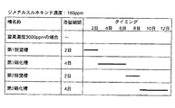
なお、図4Aのタイムチャートに、上記第1〜第3実施形態において、第1脱窒槽に導入される排水のジメチルスルホキシド濃度が約80ppmで、第2脱窒槽に導入される排水の窒素濃度が約3000ppmである場合の各槽の滞留時間を示す。また、図4Bのタイムチャートに、上記第1〜第3実施形態において、第1脱窒槽に導入される排水のジメチルスルホキシド濃度が約160ppmで、第2脱窒槽に導入される排水の窒素濃度が約3000ppmである場合の各槽の滞留時間を示す。 In the time chart of FIG. 4A, in the first to third embodiments, the dimethyl sulfoxide concentration of the wastewater introduced into the first denitrification tank is about 80 ppm, and the nitrogen concentration of the wastewater introduced into the second denitrification tank is The residence time of each tank in the case of about 3000 ppm is shown. Further, in the time chart of FIG. 4B, in the first to third embodiments, the dimethyl sulfoxide concentration of the wastewater introduced into the first denitrification tank is about 160 ppm, and the nitrogen concentration of the wastewater introduced into the second denitrification tank is The residence time of each tank in the case of about 3000 ppm is shown.
1 第1脱窒槽
2 撹拌機
3 エアーリフトポンプ
4A、4B 分離壁
5A〜5D 散気管
6、6N 第1硝化槽
7A、7B 液中膜
8A、8B 液中膜ポンプ
9A、9B 重力配管
10 排気ファン
11 スクラバー
12A、12B、12C 脱臭用汚泥の往路配管
13 脱臭用汚泥の帰路配管
14 悪臭ガス
15 処理ガス
16 ブロワー
17、17N 第2脱窒槽
18 撹拌機
19 エアーリフトポンプ
20、20N 第1硝化槽
21 悪臭含有汚泥導入配管
22 汚泥ポンプ
23 半嫌気部
24 好気部
25 半嫌気部
26 好気部
27 塩化ビニリデン充填物
28、28N 悪臭を発生する排水処理装置
29、29N 悪臭を処理する排水処理装置
30 循環ポンプ
31 マイクロナノバブル発生機
32 バルブ
33 空気吸い込み管
34 マイクロナノバブル発生槽
35 マイクロナノバブル発生槽ポンプ
DESCRIPTION OF
Claims (1)
第2の排水処理を行うと共に上記第1の排水処理部が発生する悪臭ガスを分解処理する第2の排水処理部とを備え、
上記第1の排水処理部は、
アミノエタノールとジメチルスルホキシドを含有する排水が導入される第1の脱窒槽と、
半嫌気部を有する第1の硝化槽とを有し、
上記第2の排水処理部は、
窒素排水が導入される第2の脱窒槽と、
半嫌気部を有する第2の硝化槽と、
上記第1の排水処理部からの悪臭ガスが導入されるスクラバーと、
上記第2の硝化槽から上記スクラバーに汚泥を導入する第1汚泥導入部と、
上記スクラバーから上記第2の硝化槽に上記汚泥を導入する第2汚泥導入部とを有することを特徴とする排水処理装置。 A first wastewater treatment unit that performs the first wastewater treatment and generates malodorous gas;
A second wastewater treatment unit that performs a second wastewater treatment and decomposes malodorous gas generated by the first wastewater treatment unit,
The first waste water treatment section is
A first denitrification tank into which a wastewater containing aminoethanol and dimethyl sulfoxide is introduced;
A first nitrification tank having a semi-anaerobic part,
The second wastewater treatment section is
A second denitrification tank into which nitrogen drainage is introduced;
A second nitrification tank having a semi-anaerobic part;
A scrubber into which malodorous gas from the first wastewater treatment section is introduced;
A first sludge introduction section for introducing sludge from the second nitrification tank to the scrubber;
A wastewater treatment apparatus, comprising: a second sludge introduction section for introducing the sludge from the scrubber into the second nitrification tank.
Priority Applications (2)
| Application Number | Priority Date | Filing Date | Title |
|---|---|---|---|
| JP2005366696A JP4490908B2 (en) | 2005-03-17 | 2005-12-20 | Wastewater treatment equipment |
| US11/519,217 US7713410B2 (en) | 2005-12-20 | 2006-09-12 | Wastewater treatment apparatus |
Applications Claiming Priority (2)
| Application Number | Priority Date | Filing Date | Title |
|---|---|---|---|
| JP2005076534 | 2005-03-17 | ||
| JP2005366696A JP4490908B2 (en) | 2005-03-17 | 2005-12-20 | Wastewater treatment equipment |
Publications (2)
| Publication Number | Publication Date |
|---|---|
| JP2006289343A JP2006289343A (en) | 2006-10-26 |
| JP4490908B2 true JP4490908B2 (en) | 2010-06-30 |
Family
ID=37410516
Family Applications (1)
| Application Number | Title | Priority Date | Filing Date |
|---|---|---|---|
| JP2005366696A Expired - Fee Related JP4490908B2 (en) | 2005-03-17 | 2005-12-20 | Wastewater treatment equipment |
Country Status (1)
| Country | Link |
|---|---|
| JP (1) | JP4490908B2 (en) |
Families Citing this family (7)
| Publication number | Priority date | Publication date | Assignee | Title |
|---|---|---|---|---|
| JP4485444B2 (en) * | 2005-09-28 | 2010-06-23 | シャープ株式会社 | Waste water treatment method and waste water treatment equipment |
| JP4896694B2 (en) * | 2006-12-14 | 2012-03-14 | シャープ株式会社 | Purification device |
| JP4754512B2 (en) * | 2007-02-27 | 2011-08-24 | シャープ株式会社 | Sanitizable hydroponics apparatus and hydroponics method |
| JP4996388B2 (en) * | 2007-08-03 | 2012-08-08 | オルガノ株式会社 | Method for treating water containing dimethyl sulfoxide and water treatment apparatus containing dimethyl sulfoxide |
| CN106315953B (en) * | 2016-09-09 | 2019-03-12 | 福州大学 | A kind of waste water advanced recovery processing technique of synthetic leather and device |
| CN113041835A (en) * | 2016-11-10 | 2021-06-29 | 江苏科威环保技术有限公司 | Processing system of exhaust gas that escapes in waste water |
| JP6281652B1 (en) * | 2017-03-16 | 2018-02-21 | 栗田工業株式会社 | Aerobic biological treatment equipment |
Citations (15)
| Publication number | Priority date | Publication date | Assignee | Title |
|---|---|---|---|---|
| JPH0691289A (en) * | 1992-09-11 | 1994-04-05 | Kurita Water Ind Ltd | Method for treating drainage containing dimethyl sulfoxide |
| JPH0899092A (en) * | 1994-08-03 | 1996-04-16 | Sharp Corp | Waste water treatment apparatus and method |
| JPH0970599A (en) * | 1995-09-06 | 1997-03-18 | Sharp Corp | Waste water treating device and treatment of waste water |
| JPH09314177A (en) * | 1996-05-28 | 1997-12-09 | Sharp Corp | Method and apparatus for treating organic waste water |
| JP2769973B2 (en) * | 1994-03-29 | 1998-06-25 | シャープ株式会社 | Method and apparatus for treating water to be treated containing organic sulfur compounds |
| JP2000279970A (en) * | 1999-03-31 | 2000-10-10 | Shinko Pantec Co Ltd | Treatment of organic sulfur compound-containing waste water and apparatus therefor |
| JP2002136992A (en) * | 2000-11-07 | 2002-05-14 | Sharp Corp | Neutralization method and apparatus |
| JP2002177978A (en) * | 2000-10-04 | 2002-06-25 | Sharp Corp | Treatment method for waste water and equipment for the same |
| JP3331623B2 (en) * | 1992-06-08 | 2002-10-07 | 栗田工業株式会社 | Aerobic treatment equipment |
| JP2003299935A (en) * | 2002-04-04 | 2003-10-21 | Matsushita Environment Airconditioning Eng Co Ltd | Method for treating organic exhaust gas and device |
| JP2005334780A (en) * | 2004-05-27 | 2005-12-08 | Toshiba Corp | Method and apparatus for preventing generation of bad smell when waste water is treated |
| JP2006231184A (en) * | 2005-02-24 | 2006-09-07 | Sharp Corp | Wastewater treatment apparatus and wastewater treatment method |
| JP2006272317A (en) * | 2005-03-04 | 2006-10-12 | Sharp Corp | Waste gas/waste water treatment equipment and method of treating waste gas/waste water |
| JP2006289344A (en) * | 2005-03-17 | 2006-10-26 | Sharp Corp | Exhaust gas treatment device and exhaust gas treatment method |
| JP4212588B2 (en) * | 2005-03-08 | 2009-01-21 | シャープ株式会社 | Waste water treatment apparatus and waste water treatment method |
-
2005
- 2005-12-20 JP JP2005366696A patent/JP4490908B2/en not_active Expired - Fee Related
Patent Citations (16)
| Publication number | Priority date | Publication date | Assignee | Title |
|---|---|---|---|---|
| JP3331623B2 (en) * | 1992-06-08 | 2002-10-07 | 栗田工業株式会社 | Aerobic treatment equipment |
| JPH0691289A (en) * | 1992-09-11 | 1994-04-05 | Kurita Water Ind Ltd | Method for treating drainage containing dimethyl sulfoxide |
| JP2769973B2 (en) * | 1994-03-29 | 1998-06-25 | シャープ株式会社 | Method and apparatus for treating water to be treated containing organic sulfur compounds |
| JPH0899092A (en) * | 1994-08-03 | 1996-04-16 | Sharp Corp | Waste water treatment apparatus and method |
| JPH0970599A (en) * | 1995-09-06 | 1997-03-18 | Sharp Corp | Waste water treating device and treatment of waste water |
| JPH09314177A (en) * | 1996-05-28 | 1997-12-09 | Sharp Corp | Method and apparatus for treating organic waste water |
| JP2000279970A (en) * | 1999-03-31 | 2000-10-10 | Shinko Pantec Co Ltd | Treatment of organic sulfur compound-containing waste water and apparatus therefor |
| JP2002177978A (en) * | 2000-10-04 | 2002-06-25 | Sharp Corp | Treatment method for waste water and equipment for the same |
| JP2002136992A (en) * | 2000-11-07 | 2002-05-14 | Sharp Corp | Neutralization method and apparatus |
| JP2003299935A (en) * | 2002-04-04 | 2003-10-21 | Matsushita Environment Airconditioning Eng Co Ltd | Method for treating organic exhaust gas and device |
| JP2005334780A (en) * | 2004-05-27 | 2005-12-08 | Toshiba Corp | Method and apparatus for preventing generation of bad smell when waste water is treated |
| JP2006231184A (en) * | 2005-02-24 | 2006-09-07 | Sharp Corp | Wastewater treatment apparatus and wastewater treatment method |
| JP2006272317A (en) * | 2005-03-04 | 2006-10-12 | Sharp Corp | Waste gas/waste water treatment equipment and method of treating waste gas/waste water |
| JP3893402B2 (en) * | 2005-03-04 | 2007-03-14 | シャープ株式会社 | Exhaust gas wastewater treatment apparatus and exhaust gas wastewater treatment method |
| JP4212588B2 (en) * | 2005-03-08 | 2009-01-21 | シャープ株式会社 | Waste water treatment apparatus and waste water treatment method |
| JP2006289344A (en) * | 2005-03-17 | 2006-10-26 | Sharp Corp | Exhaust gas treatment device and exhaust gas treatment method |
Also Published As
| Publication number | Publication date |
|---|---|
| JP2006289343A (en) | 2006-10-26 |
Similar Documents
| Publication | Publication Date | Title |
|---|---|---|
| JP3893402B2 (en) | Exhaust gas wastewater treatment apparatus and exhaust gas wastewater treatment method | |
| JP4212588B2 (en) | Waste water treatment apparatus and waste water treatment method | |
| JP4088630B2 (en) | Wastewater treatment equipment | |
| CN101132992B (en) | Method of wastewater treatment and wastewater treatment equipment | |
| US7615156B2 (en) | Device for in situ bioremediation of liquid waste | |
| JP4490908B2 (en) | Wastewater treatment equipment | |
| US7575684B2 (en) | Waste water treatment apparatus and waste water treatment method | |
| JP4782576B2 (en) | Wastewater treatment equipment | |
| JPH06190387A (en) | Method and apparatus for treating developer-containing waste water | |
| JP2011189286A (en) | Water treatment system for organic wastewater | |
| JP5992807B2 (en) | Waste water treatment apparatus and waste water treatment method | |
| JP4409532B2 (en) | Apparatus for treating wastewater containing high-concentration nitrogen such as livestock wastewater and manure, and its treatment method | |
| CN114315012A (en) | Excrement wastewater treatment system and method applied to scenic spot | |
| JP2004097856A (en) | Equipment and method for waste liquid treatment | |
| CN206736017U (en) | Antibiotic waste water processing unit | |
| JP2007326075A (en) | Waste water treatment method and waste water treatment equipment | |
| JP2006289344A (en) | Exhaust gas treatment device and exhaust gas treatment method | |
| US7713410B2 (en) | Wastewater treatment apparatus | |
| JP2007319783A (en) | Waste water treatment method and waste water treatment equipment | |
| JP4490848B2 (en) | Waste water treatment apparatus and waste water treatment method | |
| KR20080072685A (en) | Wastewater treatment apparatus and method | |
| JP4490659B2 (en) | Sewage treatment system | |
| KR102095467B1 (en) | Water treatment system | |
| JPH10192897A (en) | Sludge treating method | |
| JP6753106B2 (en) | Organic wastewater treatment equipment |
Legal Events
| Date | Code | Title | Description |
|---|---|---|---|
| A621 | Written request for application examination |
Free format text: JAPANESE INTERMEDIATE CODE: A621 Effective date: 20061026 |
|
| A977 | Report on retrieval |
Free format text: JAPANESE INTERMEDIATE CODE: A971007 Effective date: 20080911 |
|
| A131 | Notification of reasons for refusal |
Free format text: JAPANESE INTERMEDIATE CODE: A131 Effective date: 20081028 |
|
| A521 | Request for written amendment filed |
Free format text: JAPANESE INTERMEDIATE CODE: A523 Effective date: 20081215 |
|
| A131 | Notification of reasons for refusal |
Free format text: JAPANESE INTERMEDIATE CODE: A131 Effective date: 20100105 |
|
| A521 | Request for written amendment filed |
Free format text: JAPANESE INTERMEDIATE CODE: A523 Effective date: 20100302 |
|
| TRDD | Decision of grant or rejection written | ||
| A01 | Written decision to grant a patent or to grant a registration (utility model) |
Free format text: JAPANESE INTERMEDIATE CODE: A01 Effective date: 20100330 |
|
| A01 | Written decision to grant a patent or to grant a registration (utility model) |
Free format text: JAPANESE INTERMEDIATE CODE: A01 |
|
| A61 | First payment of annual fees (during grant procedure) |
Free format text: JAPANESE INTERMEDIATE CODE: A61 Effective date: 20100402 |
|
| FPAY | Renewal fee payment (event date is renewal date of database) |
Free format text: PAYMENT UNTIL: 20130409 Year of fee payment: 3 |
|
| R150 | Certificate of patent or registration of utility model |
Ref document number: 4490908 Country of ref document: JP Free format text: JAPANESE INTERMEDIATE CODE: R150 Free format text: JAPANESE INTERMEDIATE CODE: R150 |
|
| FPAY | Renewal fee payment (event date is renewal date of database) |
Free format text: PAYMENT UNTIL: 20130409 Year of fee payment: 3 |
|
| LAPS | Cancellation because of no payment of annual fees | ||
| S531 | Written request for registration of change of domicile |
Free format text: JAPANESE INTERMEDIATE CODE: R313531 |
|
| R360 | Written notification for declining of transfer of rights |
Free format text: JAPANESE INTERMEDIATE CODE: R360 |
|
| R360 | Written notification for declining of transfer of rights |
Free format text: JAPANESE INTERMEDIATE CODE: R360 |
|
| R371 | Transfer withdrawn |
Free format text: JAPANESE INTERMEDIATE CODE: R371 |