JP4490034B2 - Main liquid fuel injector for single combustion chamber with premixing chamber of gas turbine with low pollutant emissions - Google Patents
Main liquid fuel injector for single combustion chamber with premixing chamber of gas turbine with low pollutant emissions Download PDFInfo
- Publication number
- JP4490034B2 JP4490034B2 JP2002369155A JP2002369155A JP4490034B2 JP 4490034 B2 JP4490034 B2 JP 4490034B2 JP 2002369155 A JP2002369155 A JP 2002369155A JP 2002369155 A JP2002369155 A JP 2002369155A JP 4490034 B2 JP4490034 B2 JP 4490034B2
- Authority
- JP
- Japan
- Prior art keywords
- injection device
- liquid fuel
- main injection
- chamber
- combustion chamber
- Prior art date
- Legal status (The legal status is an assumption and is not a legal conclusion. Google has not performed a legal analysis and makes no representation as to the accuracy of the status listed.)
- Expired - Fee Related
Links
Images


Classifications
-
- F—MECHANICAL ENGINEERING; LIGHTING; HEATING; WEAPONS; BLASTING
- F23—COMBUSTION APPARATUS; COMBUSTION PROCESSES
- F23R—GENERATING COMBUSTION PRODUCTS OF HIGH PRESSURE OR HIGH VELOCITY, e.g. GAS-TURBINE COMBUSTION CHAMBERS
- F23R3/00—Continuous combustion chambers using liquid or gaseous fuel
- F23R3/28—Continuous combustion chambers using liquid or gaseous fuel characterised by the fuel supply
- F23R3/286—Continuous combustion chambers using liquid or gaseous fuel characterised by the fuel supply having fuel-air premixing devices
-
- F—MECHANICAL ENGINEERING; LIGHTING; HEATING; WEAPONS; BLASTING
- F23—COMBUSTION APPARATUS; COMBUSTION PROCESSES
- F23C—METHODS OR APPARATUS FOR COMBUSTION USING FLUID FUEL OR SOLID FUEL SUSPENDED IN A CARRIER GAS OR AIR
- F23C2900/00—Special features of, or arrangements for combustion apparatus using fluid fuels or solid fuels suspended in air; Combustion processes therefor
- F23C2900/07001—Air swirling vanes incorporating fuel injectors
Description
【0001】
【発明の属する技術分野】
本発明は、汚染物質低排出のガスタービンの、予混合室を有する(予混合室付き)単一燃焼室用の主液体燃料噴射装置に関する。
【0002】
【従来の技術】
公知のように、ガスタービンは、圧縮機及び1つ又はそれ以上の段を備えるタービンからなる機械であり、その中では、これらの構成部品が回転シャフトにより相互接続され、また少なくとも1つの燃焼室が圧縮機とタービンの間に設けられている。特に、ここでは単一燃焼室が設けられている場合について言及する。
【0003】
外部環境からの空気が圧縮機に供給されて、そこで空気は加圧される。
【0004】
加圧された空気は、ノズル又は収束部分において終端する予混合室を通って流れる。少なくとも1つ噴射器が、燃料をこの予混合室に供給し、該燃料は空気と混合されて、燃焼用の燃料空気混合気を形成する。
【0005】
従って、燃焼に必要とされる燃料は、加圧回路から燃焼室内に導入され、燃焼過程は、ガスの温度及びエンタルピーの増大を生じるように設計されている。
【0006】
パイロットフレームを生成するための並列燃料供給システムが、一般的にフレームの安定特性を向上させるために設けられる。
【0007】
最後に、高温かつ高圧のガスが、適当なダクトを通してタービンの様々な段に到達するように流され、これらタービンの様々な段が、ガスのエンタルピーをユーザが利用できる機械的エネルギーに変換する。
【0008】
ガスタービン用の燃焼室の設計において考慮すべき主な点は、フレーム安定性及び過剰空気の制御であり、その目標は燃焼にとって理想的な状態を確立することであることはよく知られている。
【0009】
また、主として窒素酸化物及び一酸化炭素の排出を減少させる燃焼を達成するために、予混合室により空気燃料混合気を形成させる傾向がある。これは、過剰燃焼空気の要因を最適化することによってなされる。
【0010】
より具体的には、従来技術では、燃焼室からすぐ上流に予混合室を設ける。
【0011】
予混合室及び燃焼室の両方は、燃焼室を出る燃焼生成物の流れと反対方向に循環する加圧空気を含む空洞によって取り囲まれている。
【0012】
前述の空気(軸流圧縮機の出口から取られた)は、予混合室で燃料と混合される燃焼空気として用いられ、また燃焼室及び燃焼生成物を冷却するための冷却空気としても用いられる。
【0013】
上述のシステムにおいては、タービンのあらゆる負荷レベルにおいて汚染物質、特に窒素酸化物の排出の低減を達成するために、空洞から予混合室の外面の開口を通して予混合室に至る燃焼空気の通路は、絞られることができる。
【0014】
この絞りは、燃焼空気と燃料との比率が最適値において一定に保たれるように、使用燃料の量の関数として施される。
【0015】
フレームが消炎されるか又はどちらにしても不安定になるのを防止するために、バーナの組が、追加のフレームの対応する組を燃焼領域に作り出すために、収束する軸線が予混合室の出口の円周方向周りに配置されるように設けられる。
【0016】
これらのバーナには、追加の燃料とタービンの圧縮機により供給された空気を更に圧縮して得られる高圧空気とが別々に供給される。この空気は、該空気に本質的に螺旋状の運動を与えるように捻られているブレードを通してバーナに送られる。
【0017】
従って、本質的にパイロットフレームであるバーナの追加のフレームを用いることによって、主要な中心燃焼フレームが安定し、該フレームが消炎されるのを防止するだけでなく、バーナにより別々に用いられる燃料及び空気の正確な量が分かっているので、システム全体は、最適な制御された点火が得られるように調節されることもできる。
【0018】
更に、バーナフレームに必要とされる追加燃料の量は、非常に少なくなり、その上、該燃料は最適状態で完全に燃焼されるので、窒素酸化物の汚染物質排出は大幅に低減される。
【0019】
しかしながら、汚染物質の排出を低減させるためには、液体燃料噴射器即ち主液体燃料噴射装置が、予混合室内に燃料空気混合気の満足できる分配をもたらすことが重要である。
【0020】
また、燃料供給チャネルは、該チャネルの壁が高温になる結果として生成される炭素堆積物が内部にも外部にもないように保たれることが必要である。
【0021】
従って、液体供給チャネルの壁の温度を低下させ、その温度を最大値にまでに制限することが必要であり、例えばGeneral Electricでは、通常最大値を120℃に特定している。
【0022】
この目的のために、液体燃料噴射器には、冷却空気用の内部流路が設けられ、これらの流路は、全ての液体燃料供給チャネルを取り囲んでいる。次に、この空気は、空気及び燃料の予混合チャネルの異なるポイントに噴射される。
【特許文献1】
米国特許公開第2003/0014975号
【0023】
【発明が解決しようとする課題】
従って、本発明の目的は、上述の欠点を克服すること、具体的には汚染物質の低排出を保証する、ガスタービンの予混合室付き単一燃焼室用の主液体燃料噴射装置を提供することである。
【0024】
また、本発明の別の目的は、良好なフレーム安定性をもたらしかつ燃焼室における圧力振動を減少させる、汚染物質低排出のガスタービンの予混合室付き単一燃焼室用の主液体燃料噴射装置を提供することである。
【0025】
本発明の更に別の目的は、高い燃焼効率が得られる、汚染物質低排出のガスタービンの予混合室付き単一燃焼室用の主液体燃料噴射装置を提供することである。
【0026】
本発明の更に別の目的は、炭素堆積物の生成の可能性を減少させることによって、高温にさらされる構成部品の平均寿命を増大させることができる、汚染物質低排出のガスタービンの予混合室付き単一燃焼室用の主液体燃料噴射装置を提供することである。
【0027】
本発明の更に別の目的は、特に信頼性が高く、単純かつ機能的であり、また製造及び保守コストが比較的低い、汚染物質低排出のガスタービンの予混合室付き単一燃焼室用の主液体燃料噴射装置を提供することである。
【0028】
【課題を解決するための手段】
本発明のこれら及び他の目的は、請求項1に記載したように汚染物質低排出のガスタービンの予混合室付き単一燃焼室用の主液体燃料噴射装置を作ることによって達成される。
【0029】
その他の特徴は、後続の請求項に特定されている。
【0030】
有利なことには、汚染物質低排出のガスタービンの予混合室付き単一燃焼室用の主液体燃料噴射装置は、液体燃料を噴射し霧化して空気と混合し、その結果燃焼室の入口の前方において燃料空気混合気の良好な分配を行う。
【0031】
更に、汚染物質低排出のガスタービンの予混合室付き単一燃焼室用の主液体燃料噴射装置はまた、高温に曝される壁の自然冷却を行い、装置の外面及び液体燃料噴射チャネルを炭素残滓の堆積によって生じる損傷に対して保護することを可能にする。
【0032】
【発明の実施の形態】
本発明による汚染物質低排出のガスタービンの予混合室付き単一燃焼室用の主液体燃料噴射装置の特徴と利点は、実例によって限定する意図ではなく添付の概略図面を参照してなされる以下の説明により一層明らかになるであろう。
【0033】
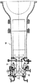
図1を参照すると、全体を符号10で表した、汚染物質低排出のガスタービンの単一燃焼室が示されており、ガスタービンは予混合室12を有してる。
【0034】
予混合室12はまた、図2、図3、図4及び図5により詳細に示す、本発明による主液体燃料噴射装置20を有する。
【0035】
主噴射装置20は、予混合室12内の燃焼領域に向かって先細になっている軸対称の細長い構造体を含む。
【0036】
より具体的には、装置20は、ほぼ円形でありかつ例えば穴24の円周方向の組を貫通するボルトにより予混合室12の軸線上に固定された基部22を有する。
【0037】
基部22から上流には、冷却空気の入口用ソケット38と、液体燃料の入口用ソケット39と、フラッシュバック熱電対、換言すれば該噴射装置20へのフラッシュバックを検知する安全装置を固定するための入口37とを有する円筒形部分40が設けられる。
【0038】
基部22を越えたところで、噴射装置20は、大きい半径の接続部分26により先細になって本質的に円筒形の部分28になる。
【0039】
この円筒形構造体28の後方で、装置20は、「ノーズ」とも呼ばれる丸みのある端部30まで再び先細になっている。
【0040】
ノーズ30の尖端において、噴射器は、冷却空気が予混合室12に流入するようにする穴を有している。冷却空気は、液体燃料を流すためのチャネルを冷却するのに用いられ、従って炭素残留物の形成を防止する。
【0041】
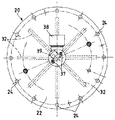
ブレード32の組は、例えば8つのブレードからなり、円筒形部分28の周りに設けられており、該ブレードは、装置20の軸線に対して等間隔で半径方向に配置されている。
【0042】
ブレード32は、中立翼形輪郭を有しており、軸方向に延びる。各ブレード32は、少なくとも1つの側面上に、少なくとも1つの液体燃料用噴射チャネル42と少なくとも1つの冷却空気噴射ポイント43とを有する。
【0043】
2つのフラッシュバック熱電対が、装置20に設けられる。これらの熱電対は、図4に示す、入口37に始まりノーズ30の近傍で終わるガイド36により正確な位置に容易に取り付けられる。
【0044】
好ましい実施形態においては、これらの熱電対は、丸みのある端部30及び室12の壁上の両方に設けられる。
【0045】
実例として説明し限定する意図ではない1つの実施形態においては、丸みのある端部30上に2つの熱電対が配置され、また室12の壁上には4つの熱電対が配置される。
【0046】
本発明による、汚染物質低排出のガスタービンの予混合室付き単一燃焼室10用の主液体噴射装置20の作動は、図を参照して上に説明した内容から明らかであり、要約すると次の通りである。
【0047】
液体燃料は、ブレード32を通して接線方向に、換言すればブレード32を貫通する空気の流れに対して垂直方向に噴射される。
【0048】
これらのブレード32は、予混合室12の主ダクト内に設置され、該主ダクトは、タービンの圧縮機により与えられる圧縮によって予熱された空気を受ける。
【0049】
従って、液体燃料及び空気間で最適に分配された混合が、燃焼領域に入る前に得られる。
【0050】
同時に、冷却空気が、各ブレード32から及びノーズ30の尖端から予混合室12内に噴射され、この冷却空気は、液体燃料供給チャネル42の温度を低く保ち、従って炭素残滓の形成を防止するのに用いられる。
【0051】
冷却空気は、安定した圧力及び温度でソケット38の入口に供給される。
【0052】
熱電対は、丸みのある端部30に配置された熱電対が最初に作動し、危険なフラッシュバックを検知して、危険なフラッシュバックが検知された場合には変換器を介してタービン制御ユニットに情報を送信する。
【0053】
本発明による主噴射装置で得られる液体燃料及び空気間の混合の分配に匹敵する液体燃料及び空気間の混合の分配を得るために、従来技術において用いられる燃焼室においては、本特許出願が関係する場合におけるような単一燃焼室に代えて、複数燃焼室又は複数の噴射ポイントを備える環状形状の燃焼室が使用されることをここで強調しておきたい。
【0054】
また、単一燃焼室の場合には、液体燃料及び空気間の良好な混合の分配の重要性が、複数燃焼室又は環状燃焼室の場合におけるより一層重大になってくること、及び、必要とされる混合の分配は、本発明による汚染物質低排出のガスタービンの予混合室付き単一燃焼室用の主液体燃料噴射装置により達成することができることを強調しておきたい。
【0055】
以上の説明は、本発明の目的である汚染物質低排出のガスタービンの予混合室付き単一燃焼室用の主液体燃料噴射装置の特徴を明白に示しており、かつ対応する利点も明らかにしている。それらの利点には、以下のことが含まれる。
・燃焼室内における圧力振動の低減と良好なフレーム安定性。
・高い燃焼効率。
・高温に曝される構成部品の平均寿命の増大。
・単純かつ信頼性の高い使用性。
・燃焼中に生成される炭素残滓の堆積により起きる損傷に対する保護。
・従来技術に従って複数燃焼室又は環状燃焼室を用いて、本発明による装置を設けることにより得られる燃料及び空気間の混合の分配に匹敵する燃料及び空気間の混合の分配を得る解決方法と比較しての、低いコストとより簡単な取付け及び保守。
【0056】
本発明による、汚染物質低排出のガスタービンの予混合室付き単一燃焼室用の主液体燃料噴射装置は、試験室テストにおいて、軸線に沿った装置の配置が僅かに変化した場合であっても、装置を通過後には空気及び燃料の混合の優れた分配が得られるという優れた結果を示した。
【0057】
更に、全負荷で数時間ガスタービンを作動させた後に、ブレード上には全く炭素堆積が見られなかったし、また全ての噴射チャネルはきれいで汚れがないことが認められた。
【0058】
最後に、このように設計された汚染物質低排出のガスタービンの予混合室付き単一燃焼室用の主液体燃料噴射装置は、その全てが本発明の技術的範囲内に含まれる多くの方法により修正及び変更することができることは明らかである。
【0059】
更に、全ての構成部品は、技術的に同等の要素と置き換えることが可能である。
【0060】
実施において、形状及び寸法だけでなく使用される材料も、技術的要求に応じて自由に変えることができる。
【0061】
従って、本発明の保護の範囲は、添付の特許請求の範囲により限界が定められる。
【0062】
特許請求の範囲内に示す参照符号は、本発明の技術的範囲を狭めるのではなくそれらを容易に理解するためのものである。
【図面の簡単な説明】
【図1】 本発明による主液体燃料噴射装置の配置を示す、汚染物質低排出のガスタービンの予混合室付き単一燃焼室の縦断面図。
【図2】 図1の主噴射装置の部分縦断面図。
【図3】 図2の主噴射装置の平面図。
【図4】 図2の平面IV―IVで切断した、図2の細部の断面図。
【図5】 液体燃料及び冷却空気を噴射するためのブレードを示す、図2の細部の拡大斜視図。
【符号の説明】
10 単一燃焼室
12 予混合室
20 主液体燃料噴射装置[0001]
BACKGROUND OF THE INVENTION
The present invention relates to a main liquid fuel injection device for a single combustion chamber having a premixing chamber (with a premixing chamber) of a gas turbine having a low pollutant emission.
[0002]
[Prior art]
As is known, a gas turbine is a machine consisting of a compressor and a turbine with one or more stages, in which these components are interconnected by a rotating shaft and at least one combustion chamber. Is provided between the compressor and the turbine. In particular, reference is made here to the case where a single combustion chamber is provided.
[0003]
Air from the outside environment is supplied to the compressor where it is pressurized.
[0004]
Pressurized air flows through a premixing chamber that terminates in a nozzle or converging section. At least one injector supplies fuel to the premixing chamber, which is mixed with air to form a fuel-air mixture for combustion.
[0005]
Therefore, the fuel required for combustion is introduced from the pressurization circuit into the combustion chamber, and the combustion process is designed to cause an increase in gas temperature and enthalpy.
[0006]
A parallel fuel supply system for generating the pilot frame is generally provided to improve the stability characteristics of the frame.
[0007]
Finally, hot, high pressure gas is flowed through appropriate ducts to reach the various stages of the turbine, which convert the enthalpy of the gas into mechanical energy available to the user.
[0008]
It is well known that the main points to consider in the design of combustion chambers for gas turbines are flame stability and excess air control, the goal of which is to establish ideal conditions for combustion. .
[0009]
Also, there is a tendency to form an air / fuel mixture in the premixing chamber to achieve combustion that primarily reduces emissions of nitrogen oxides and carbon monoxide. This is done by optimizing the factor of excess combustion air.
[0010]
More specifically, in the prior art, a premixing chamber is provided immediately upstream from the combustion chamber.
[0011]
Both the premixing chamber and the combustion chamber are surrounded by a cavity containing pressurized air that circulates in a direction opposite to the flow of combustion products exiting the combustion chamber.
[0012]
The aforementioned air (taken from the outlet of the axial compressor) is used as combustion air mixed with fuel in the premixing chamber and also as cooling air for cooling the combustion chamber and combustion products. .
[0013]
In the system described above, in order to achieve reduced emissions of pollutants, in particular nitrogen oxides, at all load levels of the turbine, the passage of combustion air from the cavity through the opening on the outer surface of the premixing chamber is Can be squeezed.
[0014]
This restriction is applied as a function of the amount of fuel used so that the ratio of combustion air to fuel is kept constant at the optimum value.
[0015]
In order to prevent the flame from being extinguished or in any case unstable, the set of burners creates a corresponding set of additional frames in the combustion zone so that the converging axis is in the premixing chamber. It is provided so as to be arranged around the circumferential direction of the outlet.
[0016]
These burners are separately supplied with additional fuel and high pressure air obtained by further compressing the air supplied by the turbine compressor. This air is sent to the burner through a blade that is twisted to impart an essentially helical motion to the air.
[0017]
Thus, using an additional frame of the burner that is essentially a pilot frame not only stabilizes the main central combustion frame and prevents it from being extinguished, but also the fuel used separately by the burner and Since the exact amount of air is known, the entire system can also be adjusted to obtain an optimal controlled ignition.
[0018]
Furthermore, the amount of additional fuel required for the burner frame is very small and, in addition, the nitrogen oxide pollutant emissions are greatly reduced since the fuel is completely burned in an optimal state.
[0019]
However, to reduce pollutant emissions, it is important that the liquid fuel injector or main liquid fuel injector provides a satisfactory distribution of the fuel-air mixture in the premix chamber.
[0020]
Also, the fuel supply channel needs to be kept so that no carbon deposits are generated inside or outside as a result of the channel walls becoming hot.
[0021]
Therefore, it is necessary to reduce the temperature of the wall of the liquid supply channel and limit the temperature to a maximum value. For example, General Electric normally specifies a maximum value of 120 ° C.
[0022]
For this purpose, the liquid fuel injector is provided with internal flow paths for cooling air, which surround all liquid fuel supply channels. This air is then injected into different points of the air and fuel premix channel.
[Patent Document 1]
US Patent Publication No. 2003/0014975
[Problems to be solved by the invention]
Accordingly, it is an object of the present invention to provide a main liquid fuel injector for a single combustion chamber with a premixing chamber of a gas turbine that overcomes the above-mentioned drawbacks and in particular ensures a low emission of pollutants. That is.
[0024]
Another object of the present invention is to provide a main liquid fuel injection system for a single combustion chamber with a premixing chamber of a low pollutant gas turbine that provides good flame stability and reduces pressure oscillations in the combustion chamber. Is to provide.
[0025]
Yet another object of the present invention is to provide a main liquid fuel injector for a single combustion chamber with a premixing chamber of a gas turbine with low pollutant emissions that provides high combustion efficiency.
[0026]
Yet another object of the present invention is to provide a pollutant low emission gas turbine premixing chamber that can increase the average life of components exposed to high temperatures by reducing the likelihood of carbon deposit formation. A main liquid fuel injection device for a single combustion chamber is provided.
[0027]
Yet another object of the present invention is for a single combustion chamber with a premixing chamber of a low pollutant gas turbine that is particularly reliable, simple and functional, and relatively low in manufacturing and maintenance costs. A main liquid fuel injection device is provided.
[0028]
[Means for Solving the Problems]
These and other objects of the invention are achieved by making a main liquid fuel injector for a single combustion chamber with a premixing chamber of a gas turbine with low pollutant emissions as claimed in claim 1.
[0029]
Other features are specified in the subsequent claims.
[0030]
Advantageously, the main liquid fuel injection system for a single combustion chamber with a premixing chamber of a gas turbine with low pollutant emissions injects and atomizes the liquid fuel and mixes it with air, so that the inlet of the combustion chamber Good distribution of the fuel-air mixture in front of the.
[0031]
In addition, the main liquid fuel injector for single combustion chamber with premixing chamber of gas turbine with low pollutant emissions also provides natural cooling of the walls exposed to high temperatures, carbonizing the outer surface of the apparatus and the liquid fuel injection channel. It makes it possible to protect against damage caused by the accumulation of residues.
[0032]
DETAILED DESCRIPTION OF THE INVENTION
Features and advantages of a main liquid fuel injection system for a single combustion chamber with a premixing chamber of a low pollutant gas turbine according to the present invention are not intended to be limited by example, but are made with reference to the accompanying schematic drawings in which: It will become clearer from the explanation of.
[0033]
Referring to FIG. 1, a single pollutant gas turbine single combustion chamber, generally designated 10, is shown, which has a
[0034]
The
[0035]
The
[0036]
More specifically, the
[0037]
Upstream from the
[0038]
Beyond the
[0039]
Behind this
[0040]
At the tip of the
[0041]
The set of
[0042]
The
[0043]
Two flashback thermocouples are provided in the
[0044]
In a preferred embodiment, these thermocouples are provided both on the
[0045]
In one embodiment described and not intended to be limiting by way of illustration, two thermocouples are disposed on the
[0046]
The operation of the main
[0047]
Liquid fuel is injected tangentially through the
[0048]
These
[0049]
Thus, an optimally distributed mixture between liquid fuel and air is obtained before entering the combustion zone.
[0050]
At the same time, cooling air is injected into each premixing
[0051]
Cooling air is supplied to the inlet of the
[0052]
The thermocouple is connected to the turbine control unit via a converter when a thermocouple located at the
[0053]
In the combustion chamber used in the prior art to obtain a mixture distribution between liquid fuel and air comparable to the distribution of mixture between liquid fuel and air obtained with the main injector according to the invention, this patent application is concerned. It should be emphasized here that instead of a single combustion chamber as in that case, an annular shaped combustion chamber with multiple combustion chambers or multiple injection points is used.
[0054]
Also, in the case of a single combustion chamber, the importance of a good mixing distribution between liquid fuel and air becomes more and more important than in the case of multiple or annular combustion chambers. It should be emphasized that the mixing distribution achieved can be achieved by a main liquid fuel injector for a single combustion chamber with a premixing chamber of a pollutant low emission gas turbine according to the present invention.
[0055]
The above description clearly shows the characteristics of the main liquid fuel injector for the single combustion chamber with premixing chamber of the low pollutant gas turbine which is the object of the present invention, and also clarifies the corresponding advantages. ing. These advantages include the following.
・ Reduced pressure vibration in the combustion chamber and good flame stability.
・ High combustion efficiency.
• Increased life expectancy of components exposed to high temperatures.
・ Simple and reliable usability.
-Protection against damage caused by the accumulation of carbon residues produced during combustion.
Compared to a solution that uses a multi-combustion chamber or an annular combustion chamber according to the prior art to obtain a fuel-air mixture distribution comparable to the fuel-air mixture distribution obtained by providing a device according to the invention. Lower cost and easier installation and maintenance.
[0056]
The main liquid fuel injection device for a single combustion chamber with a premixing chamber of a low pollutant gas turbine according to the present invention is a case where the arrangement of the device along the axis is slightly changed in a test chamber test. Also showed excellent results that an excellent distribution of air and fuel mixing was obtained after passing through the device.
[0057]
In addition, after running the gas turbine for several hours at full load, no carbon deposition was seen on the blades, and all injection channels were found to be clean and free of dirt.
[0058]
Finally, the main liquid fuel injector for a single combustion chamber with a premixing chamber of a pollutant low emission gas turbine designed in this way is a number of methods that are all within the scope of the present invention. Obviously, modifications and changes can be made.
[0059]
Furthermore, all components can be replaced by technically equivalent elements.
[0060]
In practice, the materials used as well as the shapes and dimensions can be freely changed according to the technical requirements.
[0061]
Accordingly, the scope of protection of the present invention is limited by the appended claims.
[0062]
Reference numerals appearing in the claims are not to limit the scope of the invention but to facilitate understanding thereof.
[Brief description of the drawings]
FIG. 1 is a longitudinal sectional view of a single combustion chamber with a premixing chamber of a gas pollutant low emission gas turbine showing the arrangement of a main liquid fuel injection device according to the present invention.
FIG. 2 is a partial longitudinal sectional view of the main injection device of FIG.
FIG. 3 is a plan view of the main injection device of FIG. 2;
4 is a cross-sectional view of the detail of FIG. 2 taken along the plane IV-IV of FIG.
FIG. 5 is an enlarged perspective view of the detail of FIG. 2 showing a blade for injecting liquid fuel and cooling air.
[Explanation of symbols]
10
Claims (14)
Applications Claiming Priority (2)
| Application Number | Priority Date | Filing Date | Title |
|---|---|---|---|
| IT2001A002780 | 2001-12-21 | ||
| IT2001MI002780A ITMI20012780A1 (en) | 2001-12-21 | 2001-12-21 | MAIN INJECTION DEVICE FOR LIQUID FUEL FOR SINGLE COMBUSTION CHAMBER EQUIPPED WITH PRE-MIXING CHAMBER OF A TU |
Publications (3)
| Publication Number | Publication Date |
|---|---|
| JP2003207130A JP2003207130A (en) | 2003-07-25 |
| JP2003207130A5 JP2003207130A5 (en) | 2006-02-09 |
| JP4490034B2 true JP4490034B2 (en) | 2010-06-23 |
Family
ID=11448746
Family Applications (1)
| Application Number | Title | Priority Date | Filing Date |
|---|---|---|---|
| JP2002369155A Expired - Fee Related JP4490034B2 (en) | 2001-12-21 | 2002-12-20 | Main liquid fuel injector for single combustion chamber with premixing chamber of gas turbine with low pollutant emissions |
Country Status (9)
| Country | Link |
|---|---|
| US (1) | US6834506B2 (en) |
| EP (1) | EP1321714B1 (en) |
| JP (1) | JP4490034B2 (en) |
| KR (1) | KR100760558B1 (en) |
| CA (1) | CA2413635C (en) |
| DE (1) | DE60235948D1 (en) |
| IT (1) | ITMI20012780A1 (en) |
| RU (1) | RU2320926C2 (en) |
| TW (1) | TWI296697B (en) |
Families Citing this family (18)
| Publication number | Priority date | Publication date | Assignee | Title |
|---|---|---|---|---|
| ITMI20012781A1 (en) * | 2001-12-21 | 2003-06-21 | Nuovo Pignone Spa | IMPROVED ASSEMBLY OF PRE-MIXING CHAMBER AND COMBUSTION CHAMBER, LOW POLLUTING EMISSIONS FOR GAS TURBINES WITH FUEL |
| US7165405B2 (en) * | 2002-07-15 | 2007-01-23 | Power Systems Mfg. Llc | Fully premixed secondary fuel nozzle with dual fuel capability |
| US6691516B2 (en) * | 2002-07-15 | 2004-02-17 | Power Systems Mfg, Llc | Fully premixed secondary fuel nozzle with improved stability |
| ITMI20032621A1 (en) | 2003-12-30 | 2005-06-30 | Nuovo Pignone Spa | COMBUSTION SYSTEM WITH LOW POLLUTING EMISSIONS |
| EP1821035A1 (en) * | 2006-02-15 | 2007-08-22 | Siemens Aktiengesellschaft | Gas turbine burner and method of mixing fuel and air in a swirling area of a gas turbine burner |
| US8061142B2 (en) * | 2008-04-11 | 2011-11-22 | General Electric Company | Mixer for a combustor |
| US20100024425A1 (en) * | 2008-07-31 | 2010-02-04 | General Electric Company | Turbine engine fuel nozzle |
| US8413446B2 (en) * | 2008-12-10 | 2013-04-09 | Caterpillar Inc. | Fuel injector arrangement having porous premixing chamber |
| DE102009045950A1 (en) * | 2009-10-23 | 2011-04-28 | Man Diesel & Turbo Se | swirl generator |
| EP2325542B1 (en) * | 2009-11-18 | 2013-03-20 | Siemens Aktiengesellschaft | Swirler vane, swirler and burner assembly |
| US9395084B2 (en) * | 2012-06-06 | 2016-07-19 | General Electric Company | Fuel pre-mixer with planar and swirler vanes |
| WO2015050987A1 (en) | 2013-10-04 | 2015-04-09 | United Technologies Corporation | Additive manufactured fuel nozzle core for a gas turbine engine |
| US10288293B2 (en) | 2013-11-27 | 2019-05-14 | General Electric Company | Fuel nozzle with fluid lock and purge apparatus |
| CA2933539C (en) | 2013-12-23 | 2022-01-18 | General Electric Company | Fuel nozzle with flexible support structures |
| JP6606080B2 (en) | 2013-12-23 | 2019-11-13 | ゼネラル・エレクトリック・カンパニイ | Fuel nozzle structure for air-assisted fuel injection |
| JP6611341B2 (en) * | 2016-03-30 | 2019-11-27 | 三菱重工業株式会社 | Combustor and gas turbine |
| JP6634658B2 (en) * | 2016-12-20 | 2020-01-22 | 三菱重工業株式会社 | Main nozzle, combustor and method of manufacturing main nozzle |
| RU2769616C2 (en) * | 2018-12-25 | 2022-04-04 | Ансальдо Энергия Свитзерленд Аг | Injection head for the combustion chamber of a gas turbine |
Family Cites Families (23)
| Publication number | Priority date | Publication date | Assignee | Title |
|---|---|---|---|---|
| GB1139004A (en) * | 1966-02-28 | 1969-01-08 | Mini Of Technology | Improvements in or relating to combustion devices |
| US3682390A (en) * | 1970-05-13 | 1972-08-08 | Lucas Industries Ltd | Liquid atomizing devices |
| US4154056A (en) * | 1977-09-06 | 1979-05-15 | Westinghouse Electric Corp. | Fuel nozzle assembly for a gas turbine engine |
| US4263780A (en) * | 1979-09-28 | 1981-04-28 | General Motors Corporation | Lean prechamber outflow combustor with sets of primary air entrances |
| DE3241162A1 (en) * | 1982-11-08 | 1984-05-10 | Kraftwerk Union AG, 4330 Mülheim | PRE-MIXING BURNER WITH INTEGRATED DIFFUSION BURNER |
| JPS60126521A (en) * | 1983-12-08 | 1985-07-06 | Nissan Motor Co Ltd | Fuel injection valve of combustor for gas turbine |
| US5251447A (en) * | 1992-10-01 | 1993-10-12 | General Electric Company | Air fuel mixer for gas turbine combustor |
| US5351477A (en) * | 1993-12-21 | 1994-10-04 | General Electric Company | Dual fuel mixer for gas turbine combustor |
| GB9326367D0 (en) * | 1993-12-23 | 1994-02-23 | Rolls Royce Plc | Fuel injection apparatus |
| JP2666117B2 (en) * | 1994-06-10 | 1997-10-22 | 財団法人石油産業活性化センター | Pre-evaporation premix combustor |
| US5778676A (en) * | 1996-01-02 | 1998-07-14 | General Electric Company | Dual fuel mixer for gas turbine combustor |
| JPH09210364A (en) * | 1996-02-06 | 1997-08-12 | Nissan Motor Co Ltd | Premixing combuster for gas turbine |
| US5857320A (en) * | 1996-11-12 | 1999-01-12 | Westinghouse Electric Corporation | Combustor with flashback arresting system |
| US5735466A (en) * | 1996-12-20 | 1998-04-07 | United Technologies Corporation | Two stream tangential entry nozzle |
| KR100550689B1 (en) * | 1998-02-10 | 2006-02-08 | 제너럴 일렉트릭 캄파니 | Burner with uniform fuel/air premixing for low emissions combustion |
| US6178752B1 (en) * | 1998-03-24 | 2001-01-30 | United Technologies Corporation | Durability flame stabilizing fuel injector with impingement and transpiration cooled tip |
| US6082111A (en) * | 1998-06-11 | 2000-07-04 | Siemens Westinghouse Power Corporation | Annular premix section for dry low-NOx combustors |
| US6094904A (en) * | 1998-07-16 | 2000-08-01 | United Technologies Corporation | Fuel injector with a replaceable sensor |
| EP1105678B1 (en) * | 1998-08-20 | 2004-10-20 | Siemens Aktiengesellschaft | Operating method for a hybrid burner |
| JP2001108237A (en) * | 1999-10-07 | 2001-04-20 | Hitachi Ltd | Gas turbine combustor |
| JP2001280641A (en) * | 2000-03-31 | 2001-10-10 | Mitsubishi Heavy Ind Ltd | Gas turbine combustor, and method for mixing fuel and air in gas turbine combustor |
| JP2002031343A (en) * | 2000-07-13 | 2002-01-31 | Mitsubishi Heavy Ind Ltd | Fuel injection member, burner, premixing nozzle of combustor, combustor, gas turbine and jet engine |
| JP2002039533A (en) * | 2000-07-21 | 2002-02-06 | Mitsubishi Heavy Ind Ltd | Combustor, gas turbine, and jet engine |
-
2001
- 2001-12-21 IT IT2001MI002780A patent/ITMI20012780A1/en unknown
-
2002
- 2002-12-05 CA CA002413635A patent/CA2413635C/en not_active Expired - Fee Related
- 2002-12-10 TW TW091135689A patent/TWI296697B/en not_active IP Right Cessation
- 2002-12-17 US US10/320,680 patent/US6834506B2/en not_active Expired - Fee Related
- 2002-12-18 EP EP02258734A patent/EP1321714B1/en not_active Expired - Lifetime
- 2002-12-18 DE DE60235948T patent/DE60235948D1/en not_active Expired - Lifetime
- 2002-12-20 KR KR1020020081805A patent/KR100760558B1/en not_active IP Right Cessation
- 2002-12-20 JP JP2002369155A patent/JP4490034B2/en not_active Expired - Fee Related
- 2002-12-20 RU RU2002134608/06A patent/RU2320926C2/en not_active IP Right Cessation
Also Published As
| Publication number | Publication date |
|---|---|
| TWI296697B (en) | 2008-05-11 |
| EP1321714A2 (en) | 2003-06-25 |
| TW200409887A (en) | 2004-06-16 |
| US6834506B2 (en) | 2004-12-28 |
| US20030121266A1 (en) | 2003-07-03 |
| EP1321714B1 (en) | 2010-04-14 |
| KR20030053434A (en) | 2003-06-28 |
| RU2320926C2 (en) | 2008-03-27 |
| KR100760558B1 (en) | 2007-09-20 |
| CA2413635A1 (en) | 2003-06-21 |
| CA2413635C (en) | 2009-10-13 |
| JP2003207130A (en) | 2003-07-25 |
| DE60235948D1 (en) | 2010-05-27 |
| ITMI20012780A1 (en) | 2003-06-21 |
| EP1321714A3 (en) | 2004-05-12 |
Similar Documents
| Publication | Publication Date | Title |
|---|---|---|
| JP4490034B2 (en) | Main liquid fuel injector for single combustion chamber with premixing chamber of gas turbine with low pollutant emissions | |
| US6951108B2 (en) | Gas turbine engine combustor can with trapped vortex cavity | |
| JP5860620B2 (en) | Injection nozzle for turbomachine | |
| EP1143199B1 (en) | Methods and apparatus for reducing gas turbine engine emissions | |
| JP4177812B2 (en) | Turbine engine fuel nozzle | |
| EP2647911B1 (en) | Combustor | |
| CA2393863C (en) | Pilot burner, premixing combustor, and gas turbine | |
| US11371706B2 (en) | Premixed pilot nozzle for gas turbine combustor | |
| JP2010281568A (en) | Method and apparatus for low emission gas turbine energy generation | |
| KR19990072562A (en) | Burner with uniform fuel/air premixing for low emissions combustion | |
| JP2012017971A5 (en) | ||
| JPH0828874A (en) | Gas turbine combustion device and gas turbine | |
| KR101626692B1 (en) | Burner | |
| JP2014122784A (en) | System for supplying fuel to combustor | |
| CN112594735B (en) | Gas turbine combustor | |
| JP4362284B2 (en) | Improved combination of pollutant low emission premixing and combustion chambers for gas turbines operating with liquid and / or gaseous fuels | |
| JP3192055B2 (en) | Gas turbine combustor | |
| KR100679596B1 (en) | Radial inflow dual fuel injector | |
| KR20190109955A (en) | Nozzle for combustor, combustor, and gas turbine including the same | |
| EP2383517A2 (en) | Fluid cooled injection nozzle assembly for a gas turbomachine | |
| KR100760557B1 (en) | Improved liquid fuel injector for burners of gas turbines | |
| KR20190136383A (en) | Nozzle for combustor, combustor, and gas turbine including the same | |
| KR102071324B1 (en) | Nozzle for combustor, combustor, and gas turbine including the same | |
| KR20190048053A (en) | Combustor and gas turbine comprising the same | |
| KR101041466B1 (en) | The low NOx gas turbine combustor having the multi-fuel mixing device |
Legal Events
| Date | Code | Title | Description |
|---|---|---|---|
| A521 | Written amendment |
Free format text: JAPANESE INTERMEDIATE CODE: A523 Effective date: 20051215 |
|
| A621 | Written request for application examination |
Free format text: JAPANESE INTERMEDIATE CODE: A621 Effective date: 20051215 |
|
| A131 | Notification of reasons for refusal |
Free format text: JAPANESE INTERMEDIATE CODE: A131 Effective date: 20080513 |
|
| A601 | Written request for extension of time |
Free format text: JAPANESE INTERMEDIATE CODE: A601 Effective date: 20080808 |
|
| A602 | Written permission of extension of time |
Free format text: JAPANESE INTERMEDIATE CODE: A602 Effective date: 20080813 |
|
| A521 | Written amendment |
Free format text: JAPANESE INTERMEDIATE CODE: A523 Effective date: 20081111 |
|
| A131 | Notification of reasons for refusal |
Free format text: JAPANESE INTERMEDIATE CODE: A131 Effective date: 20090331 |
|
| A601 | Written request for extension of time |
Free format text: JAPANESE INTERMEDIATE CODE: A601 Effective date: 20090626 |
|
| RD02 | Notification of acceptance of power of attorney |
Free format text: JAPANESE INTERMEDIATE CODE: A7422 Effective date: 20090626 |
|
| RD04 | Notification of resignation of power of attorney |
Free format text: JAPANESE INTERMEDIATE CODE: A7424 Effective date: 20090626 |
|
| A602 | Written permission of extension of time |
Free format text: JAPANESE INTERMEDIATE CODE: A602 Effective date: 20090701 |
|
| A521 | Written amendment |
Free format text: JAPANESE INTERMEDIATE CODE: A523 Effective date: 20090918 |
|
| TRDD | Decision of grant or rejection written | ||
| A01 | Written decision to grant a patent or to grant a registration (utility model) |
Free format text: JAPANESE INTERMEDIATE CODE: A01 Effective date: 20100309 |
|
| A01 | Written decision to grant a patent or to grant a registration (utility model) |
Free format text: JAPANESE INTERMEDIATE CODE: A01 |
|
| A61 | First payment of annual fees (during grant procedure) |
Free format text: JAPANESE INTERMEDIATE CODE: A61 Effective date: 20100401 |
|
| FPAY | Renewal fee payment (event date is renewal date of database) |
Free format text: PAYMENT UNTIL: 20130409 Year of fee payment: 3 |
|
| R150 | Certificate of patent or registration of utility model |
Free format text: JAPANESE INTERMEDIATE CODE: R150 |
|
| FPAY | Renewal fee payment (event date is renewal date of database) |
Free format text: PAYMENT UNTIL: 20130409 Year of fee payment: 3 |
|
| FPAY | Renewal fee payment (event date is renewal date of database) |
Free format text: PAYMENT UNTIL: 20140409 Year of fee payment: 4 |
|
| R250 | Receipt of annual fees |
Free format text: JAPANESE INTERMEDIATE CODE: R250 |
|
| R250 | Receipt of annual fees |
Free format text: JAPANESE INTERMEDIATE CODE: R250 |
|
| LAPS | Cancellation because of no payment of annual fees |