JP4489006B2 - Non-aqueous electrolyte secondary battery - Google Patents
Non-aqueous electrolyte secondary battery Download PDFInfo
- Publication number
- JP4489006B2 JP4489006B2 JP2005322128A JP2005322128A JP4489006B2 JP 4489006 B2 JP4489006 B2 JP 4489006B2 JP 2005322128 A JP2005322128 A JP 2005322128A JP 2005322128 A JP2005322128 A JP 2005322128A JP 4489006 B2 JP4489006 B2 JP 4489006B2
- Authority
- JP
- Japan
- Prior art keywords
- negative electrode
- positive electrode
- secondary battery
- aqueous electrolyte
- active material
- Prior art date
- Legal status (The legal status is an assumption and is not a legal conclusion. Google has not performed a legal analysis and makes no representation as to the accuracy of the status listed.)
- Expired - Fee Related
Links
Images


Classifications
-
- Y—GENERAL TAGGING OF NEW TECHNOLOGICAL DEVELOPMENTS; GENERAL TAGGING OF CROSS-SECTIONAL TECHNOLOGIES SPANNING OVER SEVERAL SECTIONS OF THE IPC; TECHNICAL SUBJECTS COVERED BY FORMER USPC CROSS-REFERENCE ART COLLECTIONS [XRACs] AND DIGESTS
- Y02—TECHNOLOGIES OR APPLICATIONS FOR MITIGATION OR ADAPTATION AGAINST CLIMATE CHANGE
- Y02E—REDUCTION OF GREENHOUSE GAS [GHG] EMISSIONS, RELATED TO ENERGY GENERATION, TRANSMISSION OR DISTRIBUTION
- Y02E60/00—Enabling technologies; Technologies with a potential or indirect contribution to GHG emissions mitigation
- Y02E60/10—Energy storage using batteries
-
- Y—GENERAL TAGGING OF NEW TECHNOLOGICAL DEVELOPMENTS; GENERAL TAGGING OF CROSS-SECTIONAL TECHNOLOGIES SPANNING OVER SEVERAL SECTIONS OF THE IPC; TECHNICAL SUBJECTS COVERED BY FORMER USPC CROSS-REFERENCE ART COLLECTIONS [XRACs] AND DIGESTS
- Y02—TECHNOLOGIES OR APPLICATIONS FOR MITIGATION OR ADAPTATION AGAINST CLIMATE CHANGE
- Y02P—CLIMATE CHANGE MITIGATION TECHNOLOGIES IN THE PRODUCTION OR PROCESSING OF GOODS
- Y02P70/00—Climate change mitigation technologies in the production process for final industrial or consumer products
- Y02P70/50—Manufacturing or production processes characterised by the final manufactured product
Description
本発明は、非水電解液二次電池に係わる。 The present invention relates to a non-aqueous electrolyte secondary battery.
現在、携帯電話などの携帯機器向けの非水電解液二次電池として、リチウムイオン二次電池が商品化されている。この電池は、正極にリチウムコバルト酸化物(LiCoO2)、負極に黒鉛質材料や炭素質材料、非水電解液にリチウム塩を溶解した有機溶媒、セパレータに多孔質膜が用いられている。前記電解液の溶媒としては低粘度、低沸点の非水溶媒が用いられている。 Currently, lithium ion secondary batteries are commercialized as non-aqueous electrolyte secondary batteries for portable devices such as mobile phones. In this battery, a lithium cobalt oxide (LiCoO 2 ) is used for the positive electrode, a graphite material or a carbonaceous material is used for the negative electrode, an organic solvent in which a lithium salt is dissolved in a nonaqueous electrolytic solution, and a porous film is used for the separator. A non-aqueous solvent having a low viscosity and a low boiling point is used as the solvent for the electrolytic solution.
例えば特許文献1(特開平4−14769号公報)には、プロピレンカーボネートとエチレンカーボネートとγ−ブチロラクトンからなる混合溶媒を主体とし、γ−ブチロラクトンの比率が溶媒全体の10〜50体積%である電解液を備えた非水電解液二次電池が記載されている。この公報では、円筒形非水電解液二次電池の低温放電特性を改善することを目的としている。 For example, Patent Document 1 (Japanese Patent Laid-Open No. 4-14769) discloses an electrolysis in which a mixed solvent composed of propylene carbonate, ethylene carbonate and γ-butyrolactone is mainly used, and the ratio of γ-butyrolactone is 10 to 50% by volume of the whole solvent. A non-aqueous electrolyte secondary battery with a solution is described. This publication aims to improve the low-temperature discharge characteristics of a cylindrical non-aqueous electrolyte secondary battery.
ところで、携帯機器の薄型化に伴って電池の厚さを薄くすることが要望されている。このためには、正極、負極、セパレータ及び非水電解液を収納する外装材の厚さを薄くする必要がある。しかしながら、前述した特許文献1(特開平4−14769号公報)に記載されたγ−ブチロラクトンの含有量が10〜50体積%である溶媒を含む非水電解液を備えたリチウムイオン二次電池は、初充電時に負極からガス発生が多くなったり、60℃以上の高温に貯蔵した時に正極と非水電解液が反応して非水電解液の酸化分解が生じ、ガス発生が起きる。このため、外装材の厚さを薄くすると、このガス発生により外装材が膨れ、変形するという問題点を生じる。外装材が変形すると、電池が電子機器に納まらなくなったり、あるいは電子機器の誤作動を招く恐れがある。 By the way, it is desired to reduce the thickness of the battery as the portable device becomes thinner. For this purpose, it is necessary to reduce the thickness of the exterior material that houses the positive electrode, the negative electrode, the separator, and the non-aqueous electrolyte. However, a lithium ion secondary battery provided with a non-aqueous electrolyte containing a solvent having a γ-butyrolactone content of 10 to 50% by volume described in Patent Document 1 (Japanese Patent Laid-Open No. 4-14769) described above is The gas generation from the negative electrode during the initial charge is increased, or when stored at a high temperature of 60 ° C. or higher, the positive electrode and the non-aqueous electrolyte react to cause oxidative decomposition of the non-aqueous electrolyte, resulting in gas generation. For this reason, when the thickness of the exterior material is reduced, there arises a problem that the exterior material is expanded and deformed by the generation of gas. If the exterior material is deformed, the battery may not fit in the electronic device, or the electronic device may malfunction.
一方、特許文献2(特開平11−97062号公報)には、γ−ブチロラクトンの比率が100体積%である溶媒にホウフッ化リチウム(LiBF4)を溶解させたものを非水電解液として備える非水電解液二次電池が開示されている。この公報では、リチウムコバルト複合酸化物を活物質として含む正極が非水電解液により酸化分解されるのを抑制することを目的としている。 On the other hand, in Patent Document 2 (Japanese Patent Laid-Open No. 11-97062), a nonaqueous electrolytic solution in which lithium borofluoride (LiBF 4 ) is dissolved in a solvent having a γ-butyrolactone ratio of 100% by volume is provided. A water electrolyte secondary battery is disclosed. This publication aims to suppress the oxidative decomposition of a positive electrode containing a lithium cobalt composite oxide as an active material by a non-aqueous electrolyte.
しかしながら、特許文献2(特開平11−97062号公報)に開示されたγ−ブチロラクトンの比率が100体積%である溶媒にホウフッ化リチウム(LiBF4)を溶解させた非水電解液は、負極と反応して還元分解が生じやすい。その結果、負極において電流集中が生じやすくなるため、負極表面にリチウム金属が析出したり、あるいは負極界面のインピーダンスが高くなり、負極の充放電効率が低下し、充放電サイクル特性の低下を招く。 However, a nonaqueous electrolytic solution in which lithium borofluoride (LiBF 4 ) is dissolved in a solvent having a γ-butyrolactone ratio of 100% by volume disclosed in Patent Document 2 (Japanese Patent Application Laid-Open No. 11-97062) includes: Reductive decomposition is likely to occur due to reaction. As a result, current concentration is likely to occur in the negative electrode, so that lithium metal is deposited on the negative electrode surface, or the impedance at the negative electrode interface is increased, the charge / discharge efficiency of the negative electrode is lowered, and charge / discharge cycle characteristics are degraded.
また、非水電解液二次電池においては、大電流放電特性及び充放電サイクル特性の更なる改善が要望されている。
本発明の目的は、放電容量、大電流放電特性及び充放電サイクル特性に優れる非水電解液二次電池を提供しようとするものである。 An object of the present invention is to provide a non-aqueous electrolyte secondary battery excellent in discharge capacity, large current discharge characteristics and charge / discharge cycle characteristics.
本発明によれば、正極と、リチウムイオンを吸蔵・放出する材料を含む負極と、前記正極及び前記負極の間に配置されるセパレータとを備える電極群;前記電極群に含浸され、非水溶媒と、前記非水溶媒に溶解されるリチウム塩とを含む非水電解液;前記電極群が収納され、樹脂層を含む厚さが0.5mm以下のシートからなる外装材;を具備し、
前記非水溶媒は、γ−ブチロラクトンを非水溶媒全体の50体積%より多く、95体積%以下含有する非水電解液二次電池が提供される。
According to the present invention, an electrode group comprising a positive electrode, a negative electrode containing a material that absorbs and releases lithium ions, and a separator disposed between the positive electrode and the negative electrode; the electrode group impregnated with a nonaqueous solvent And a non-aqueous electrolyte solution containing a lithium salt dissolved in the non-aqueous solvent; an exterior material made of a sheet having a thickness of 0.5 mm or less containing the electrode group and including a resin layer;
A non-aqueous electrolyte secondary battery is provided in which the non-aqueous solvent contains γ-butyrolactone in an amount of more than 50% by volume and not more than 95% by volume of the whole non-aqueous solvent.
本発明によれば、正極と、リチウムイオンを吸蔵・放出する材料を含む負極と、前記正極及び前記負極の間に配置されるセパレータとを備える電極群;前記電極群に含浸され、非水溶媒と、前記非水溶媒に溶解されるリチウム塩とを含む非水電解液;前記電極群が収納される厚さが0.3mm以下の外装材;を具備し、
前記非水溶媒は、γ−ブチロラクトンを非水溶媒全体の50体積%より多く、95体積%以下含有する非水電解液二次電池が提供される。
According to the present invention, an electrode group comprising a positive electrode, a negative electrode containing a material that absorbs and releases lithium ions, and a separator disposed between the positive electrode and the negative electrode; the electrode group impregnated with a nonaqueous solvent And a non-aqueous electrolyte solution containing a lithium salt dissolved in the non-aqueous solvent; an exterior material having a thickness of 0.3 mm or less in which the electrode group is housed;
A non-aqueous electrolyte secondary battery is provided in which the non-aqueous solvent contains γ-butyrolactone in an amount of more than 50% by volume and not more than 95% by volume of the whole non-aqueous solvent.
本発明によれば、正極集電体及び前記正極集電体の片面もしくは両面に担持される正極活物質層を含む正極と、負極集電体及び前記負極集電体の片面もしくは両面に担持され、リチウムイオンを吸蔵・放出する材料を含有する負極活物質層を含む負極と、前記正極及び前記負極の間に配置されるセパレータとを備える電極群;前記電極群に含浸され、非水溶媒と、前記非水溶媒に溶解されるリチウム塩とを含む非水電解液;前記電極群が収納され、樹脂層を含む厚さが0.5mm以下のシートからなる外装材;を具備し、
前記正極活物質層の空隙率を前記負極活物質層の空隙率に比べて低くし、前記正極活物質層の厚さは10〜100μmであり、
前記非水溶媒は、γ−ブチロラクトンを非水溶媒全体の40体積%以上95体積%以下含有する非水電解液二次電池が提供される。
According to the present invention, a positive electrode including a positive electrode current collector and a positive electrode active material layer supported on one or both surfaces of the positive electrode current collector, and supported on one or both surfaces of the negative electrode current collector and the negative electrode current collector. An electrode group comprising a negative electrode including a negative electrode active material layer containing a material that absorbs and releases lithium ions; and a separator disposed between the positive electrode and the negative electrode; and a nonaqueous solvent impregnated in the electrode group; A non-aqueous electrolyte containing a lithium salt dissolved in the non-aqueous solvent; an exterior material made of a sheet having a thickness of 0.5 mm or less containing the electrode group and including a resin layer;
The porosity of the positive electrode active material layer is lower than the porosity of the negative electrode active material layer, and the thickness of the positive electrode active material layer is 10 to 100 μm,
A non-aqueous electrolyte secondary battery in which the non-aqueous solvent contains γ-butyrolactone in an amount of 40% by volume to 95% by volume of the whole non-aqueous solvent is provided.
本発明によれば、正極集電体及び前記正極集電体の片面もしくは両面に担持される正極活物質層を含む正極と、負極集電体及び前記負極集電体の片面もしくは両面に担持され、リチウムイオンを吸蔵・放出する材料を含有する負極活物質層を含む負極と、前記正極及び前記負極の間に配置されるセパレータとを備える電極群;前記電極群に含浸され、非水溶媒と、前記非水溶媒に溶解されるリチウム塩とを含む非水電解液;前記電極群が収納される厚さが0.3mm以下の外装材;を具備し、
前記正極活物質層の空隙率を前記負極活物質層の空隙率に比べて低くし、前記正極活物質層の厚さは10〜100μmであり、前記非水溶媒は、γ−ブチロラクトンを非水溶媒全体の40体積%以上95体積%以下含有する非水電解液二次電池が提供される。
According to the present invention, a positive electrode including a positive electrode current collector and a positive electrode active material layer supported on one or both surfaces of the positive electrode current collector, and supported on one or both surfaces of the negative electrode current collector and the negative electrode current collector. An electrode group comprising a negative electrode including a negative electrode active material layer containing a material that absorbs and releases lithium ions; and a separator disposed between the positive electrode and the negative electrode; and a nonaqueous solvent impregnated in the electrode group; A non-aqueous electrolyte solution containing a lithium salt dissolved in the non-aqueous solvent; an exterior material having a thickness of 0.3 mm or less in which the electrode group is housed;
The porosity of the positive electrode active material layer is lower than the porosity of the negative electrode active material layer, the thickness of the positive electrode active material layer is 10 to 100 μm, and the non-aqueous solvent is γ-butyrolactone is non-aqueous. A nonaqueous electrolyte secondary battery containing 40% by volume or more and 95% by volume or less of the entire solvent is provided.
本発明によれば、高温で貯蔵した際の外装材の変形が抑制され、重量エネルギー密度、体積エネルギー密度、大電流放電特性及び充放電サイクル特性が向上された非水電解液二次電池を提供することができる。 According to the present invention, there is provided a non-aqueous electrolyte secondary battery in which deformation of an exterior material when stored at a high temperature is suppressed and weight energy density, volume energy density, large current discharge characteristics and charge / discharge cycle characteristics are improved. can do.
本発明に係る第1の非水電解液二次電池は、正極と、リチウムイオンを吸蔵・放出する材料を含む負極と、前記正極及び前記負極の間に配置されるセパレータとを備える電極群;前記電極群に含浸され、非水溶媒と、前記非水溶媒に溶解されるリチウム塩とを含む非水電解液;前記電極群が収納される外装材;を具備する。また、前記非水溶媒は、γ−ブチロラクトンを非水溶媒全体の50体積%より多く、95体積%以下含有する。 The first non-aqueous electrolyte secondary battery according to the present invention includes an electrode group including a positive electrode, a negative electrode including a material that absorbs and releases lithium ions, and a separator disposed between the positive electrode and the negative electrode; A non-aqueous electrolyte containing a non-aqueous solvent and a lithium salt dissolved in the non-aqueous solvent; and an exterior material in which the electrode group is housed. The non-aqueous solvent contains γ-butyrolactone in an amount of more than 50% by volume and not more than 95% by volume of the whole non-aqueous solvent.
この二次電池は、前記正極、前記負極及び前記セパレータが一体化されていなくても良いが、以下の(a)、または(b)に説明するような条件で一体化されていることが好ましい。 In this secondary battery, the positive electrode, the negative electrode, and the separator do not have to be integrated, but it is preferable that they are integrated under the conditions described in (a) or (b) below. .
(a)前記正極及び前記セパレータがこれらの境界の少なくとも一部に存在する接着性を有する高分子により一体化されていると共に、前記負極及び前記セパレータがこれらの境界の少なくとも一部に存在する接着性を有する高分子により一体化されている。特に、前記正極及び前記セパレータがこれらの内部及び境界に点在する接着性を有する高分子により一体化されていると共に、前記負極及び前記セパレータがこれらの内部及び境界に点在する接着性を有する高分子により一体化されていることが望ましい。 (A) Adhesion in which the positive electrode and the separator are integrated by an adhesive polymer present at at least a part of these boundaries, and the negative electrode and the separator are present at at least a part of these boundaries It is integrated with a polymer having properties. In particular, the positive electrode and the separator are integrated with an adhesive polymer scattered in the interior and boundary thereof, and the negative electrode and the separator have adhesiveness scattered in the interior and boundary thereof. It is desirable that they are integrated by a polymer.
(b)前記正極、前記負極及び前記セパレータが、前記正極及び前記負極に含まれる結着剤を熱硬化させることにより一体化されている。 (B) The positive electrode, the negative electrode, and the separator are integrated by thermosetting the binder contained in the positive electrode and the negative electrode.
この(a)または(b)の構成にすることによって、外装材の膨れをより一層低減することができる。 By adopting the configuration of (a) or (b), the swelling of the exterior material can be further reduced.
また、前記二次電池は、電池容量(Ah)と1kHzの電池内部インピーダンス(mΩ)の積が10mΩ・Ah以上、110mΩ・Ah以下であることが望ましい。容量とインピーダンスの積を前記範囲内にすることによって、大電流放電特性と充放電サイクル特性をより向上することができる。ここで、電池容量とは、公称容量あるいは0.2Cで放電した際の放電容量である。より好ましい範囲は、20mΩ・Ah以上、60mΩ・Ah以下である。 The secondary battery preferably has a product of battery capacity (Ah) and 1 kHz battery internal impedance (mΩ) of 10 mΩ · Ah or more and 110 mΩ · Ah or less. By setting the product of the capacity and the impedance within the above range, the large current discharge characteristics and the charge / discharge cycle characteristics can be further improved. Here, the battery capacity is a nominal capacity or a discharge capacity when discharged at 0.2C. A more preferable range is 20 mΩ · Ah or more and 60 mΩ · Ah or less.
電池容量とインピーダンスの積を10mΩ・Ah以上、110mΩ・Ah以下にするのは、例えば、後述する(I)の製造方法か、あるいは後述する(II)の製造方法により可能である。但し、(I)において、接着性高分子の添加量、接着性高分子の分布及び初充電条件を、電池容量とインピーダンスの積が10mΩ・Ah以上、110mΩ・Ah以下になるように設定する。また、(II)においては、電極群を成形する際の温度とプレス圧、及び初充電条件を、電池容量とインピーダンスの積が10mΩ・Ah以上、110mΩ・Ah以下になるように設定する。 The product of the battery capacity and the impedance can be 10 mΩ · Ah or more and 110 mΩ · Ah or less, for example, by the manufacturing method (I) described later or the manufacturing method (II) described later. However, in (I), the addition amount of the adhesive polymer, the distribution of the adhesive polymer, and the initial charging conditions are set so that the product of the battery capacity and the impedance is 10 mΩ · Ah or more and 110 mΩ · Ah or less. In (II), the temperature, press pressure, and initial charge condition when forming the electrode group are set so that the product of the battery capacity and impedance is 10 mΩ · Ah or more and 110 mΩ · Ah or less.
以下、前述した(a)を満足する電極群を備える非水電解液二次電池について説明する。 Hereinafter, a non-aqueous electrolyte secondary battery including an electrode group that satisfies the above-described (a) will be described.
1)正極
この正極は、活物質を含む正極層が集電体の片面もしくは両面に担持された構造を有する。
1) Positive electrode This positive electrode has a structure in which a positive electrode layer containing an active material is supported on one side or both sides of a current collector.
前記正極層は、正極活物質及び導電剤を含む。また、前記正極層は、接着性を有する高分子とは別に、正極活物質同士を結着する結着剤を含んでいる。 The positive electrode layer includes a positive electrode active material and a conductive agent. In addition, the positive electrode layer includes a binder that binds the positive electrode active materials to each other, apart from the adhesive polymer.
前記正極活物質としては、種々の酸化物、例えば二酸化マンガン、リチウムマンガン複合酸化物、リチウム含有ニッケル酸化物、リチウム含有コバルト酸化物、リチウム含有ニッケルコバルト酸化物、リチウム含有鉄酸化物、リチウムを含むバナジウム酸化物や、二硫化チタン、二硫化モリブデンなどのカルコゲン化合物などを挙げることができる。中でも、リチウム含有コバルト酸化物(例えば、LiCoO2 )、リチウム含有ニッケルコバルト酸化物(例えば、LiNi0.8 Co0.2 O2 )、リチウムマンガン複合酸化物(例えば、LiMn2 O4 、LiMnO2 )を用いると、高電圧が得られるために好ましい。 Examples of the positive electrode active material include various oxides such as manganese dioxide, lithium manganese composite oxide, lithium-containing nickel oxide, lithium-containing cobalt oxide, lithium-containing nickel cobalt oxide, lithium-containing iron oxide, and lithium. Examples thereof include vanadium oxide and chalcogen compounds such as titanium disulfide and molybdenum disulfide. Among them, when a lithium-containing cobalt oxide (for example, LiCoO 2 ), a lithium-containing nickel cobalt oxide (for example, LiNi 0.8 Co 0.2 O 2 ), or a lithium manganese composite oxide (for example, LiMn 2 O 4 , LiMnO 2 ) is used. This is preferable because a high voltage can be obtained.
前記導電剤としては、例えばアセチレンブラック、カーボンブラック、黒鉛等を挙げることができる。 Examples of the conductive agent include acetylene black, carbon black, and graphite.
前記結着剤は、活物質を集電体に保持させ、かつ活物質同士をつなぐ機能を有する。前記結着剤としては、例えばポリテトラフルオロエチレン(PTFE)、ポリフッ化ビニリデン(PVdF)、エチレン−プロピレン−ジエン共重合体(EPDM)、スチレン−ブタジエンゴム(SBR)等を用いることができる。 The binder has a function of holding the active material on the current collector and connecting the active materials to each other. Examples of the binder include polytetrafluoroethylene (PTFE), polyvinylidene fluoride (PVdF), ethylene-propylene-diene copolymer (EPDM), and styrene-butadiene rubber (SBR).
前記正極活物質、導電剤および結着剤の配合割合は、正極活物質80〜95重量%、導電剤3〜20重量%、結着剤2〜7重量%の範囲にすることが好ましい。 The mixing ratio of the positive electrode active material, the conductive agent and the binder is preferably in the range of 80 to 95% by weight of the positive electrode active material, 3 to 20% by weight of the conductive agent, and 2 to 7% by weight of the binder.
前記集電体としては、多孔質構造の導電性基板か、あるいは無孔の導電性基板を用いることができる。これら導電性基板は、例えば、アルミニウム、ステンレス、またはニッケルから形成することができる。 As the current collector, a conductive substrate having a porous structure or a non-porous conductive substrate can be used. These conductive substrates can be formed from, for example, aluminum, stainless steel, or nickel.
中でも、直径3mm以下の孔が10cm2 当り1個以上の割合で存在する二次元的な多孔質構造を有する導電性基板を用いることが好ましい。すなわち、導電性基板に開口された孔の直径が3mmよりも大きくなると、十分な正極強度が得られなくなる恐れがある。一方、直径3mm以下の孔の存在割合が前記範囲よりも少なくなると、電極群に非水電解液を均一に浸透させることが困難になるため、十分な充放電サイクル特性が得られなくなる恐れがある。孔の直径は、0.1〜1mmの範囲にすることがより好ましい。また、孔の存在割合は、10cm2 当り10〜20個の範囲にすることがより好ましい。 Among them, it is preferable to use a conductive substrate having a two-dimensional porous structure in which holes having a diameter of 3 mm or less exist at a rate of 1 or more per 10 cm 2 . That is, when the diameter of the hole opened in the conductive substrate is larger than 3 mm, there is a possibility that sufficient positive electrode strength cannot be obtained. On the other hand, if the proportion of holes having a diameter of 3 mm or less is smaller than the above range, it is difficult to uniformly infiltrate the non-aqueous electrolyte into the electrode group, so that sufficient charge / discharge cycle characteristics may not be obtained. . The diameter of the hole is more preferably in the range of 0.1 to 1 mm. Moreover, it is more preferable that the existence ratio of the holes is in the range of 10 to 20 per 10 cm 2 .
前述した直径3mm以下の孔が10cm2 当り1個以上の割合で存在する二次元的な多孔質構造を有する導電性基板は、厚さを15〜100μmの範囲にすることが好ましい。厚さを15μm未満にすると、十分な正極強度が得られなくなる恐れがある。一方、厚さが100μmを越えると、電池重量および電極群の厚さが増加し、薄型二次電池の重量エネルギー密度や、体積エネルギー密度を十分に高くすることが困難になる恐れがある。厚さのより好ましい範囲は、30〜80μmである。 The conductive substrate having a two-dimensional porous structure in which holes having a diameter of 3 mm or less are present at a rate of 1 or more per 10 cm 2 is preferably in the range of 15 to 100 μm. If the thickness is less than 15 μm, sufficient positive electrode strength may not be obtained. On the other hand, if the thickness exceeds 100 μm, the battery weight and the thickness of the electrode group increase, which may make it difficult to sufficiently increase the weight energy density and volume energy density of the thin secondary battery. A more preferable range of the thickness is 30 to 80 μm.
2)負極
前記負極は、負極層が集電体の片面もしくは両面に担持された構造を有する。
2) Negative electrode The negative electrode has a structure in which a negative electrode layer is supported on one side or both sides of a current collector.
前記負極層は、リチウムイオンを吸蔵・放出する炭素質物を含む。また、前記負極層は、接着性を有する高分子とは別に、負極材料を結着する結着剤を含んでいる。 The negative electrode layer includes a carbonaceous material that occludes / releases lithium ions. The negative electrode layer contains a binder for binding the negative electrode material, in addition to the adhesive polymer.
前記炭素質物としては、黒鉛、コークス、炭素繊維、球状炭素などの黒鉛質材料もしくは炭素質材料、熱硬化性樹脂、等方性ピッチ、メソフェーズピッチ、メソフェーズピッチ系炭素繊維、メソフェーズ小球体など(特に、メソフェーズピッチ系炭素繊維が容量や充放電サイクル特性が高くなり好ましい)に500〜3000℃で熱処理を施すことにより得られる黒鉛質材料または炭素質材料等を挙げることができる。中でも、前記熱処理の温度を2000℃以上にすることにより得られ、(002)面の面間隔d002 が0.340nm以下である黒鉛結晶を有する黒鉛質材料を用いるのが好ましい。このような黒鉛質材料を炭素質物として含む負極を備えた非水電解液二次電池は、電池容量および大電流放電特性を大幅に向上することができる。前記面間隔d002 は、0.336nm以下であることが更に好ましい。 Examples of the carbonaceous material include graphite or carbonaceous materials such as graphite, coke, carbon fiber, and spherical carbon, thermosetting resin, isotropic pitch, mesophase pitch, mesophase pitch-based carbon fiber, mesophase microspheres, etc. And a mesophase pitch-based carbon fiber is preferable because of its high capacity and charge / discharge cycle characteristics), and a graphite material or a carbonaceous material obtained by heat treatment at 500 to 3000 ° C. Among them, it is preferable to use a graphitic material having graphite crystals obtained by setting the temperature of the heat treatment to 2000 ° C. or more and having a (002) plane spacing d 002 of 0.340 nm or less. A non-aqueous electrolyte secondary battery equipped with a negative electrode containing such a graphite material as a carbonaceous material can greatly improve battery capacity and large current discharge characteristics. The spacing d 002 is more preferably at most 0.336 nm.
前記結着剤としては、例えばポリテトラフルオロエチレン(PTFE)、ポリフッ化ビニリデン(PVdF)、エチレン−プロピレン−ジエン共重合体(EPDM)、スチレン−プタジエンゴム(SBR)、カルボキシメチルセルロース(CMC)等を用いることができる。 Examples of the binder include polytetrafluoroethylene (PTFE), polyvinylidene fluoride (PVdF), ethylene-propylene-diene copolymer (EPDM), styrene-butadiene rubber (SBR), carboxymethyl cellulose (CMC), and the like. be able to.
前記炭素質物及び前記結着剤の配合割合は、炭素質物90〜98重量%、結着剤2〜20重量%の範囲であることが好ましい。 The blending ratio of the carbonaceous material and the binder is preferably in the range of 90 to 98% by weight of the carbonaceous material and 2 to 20% by weight of the binder.
前記集電体としては、多孔質構造の導電性基板か、あるいは無孔の導電性基板を用いることができる。これら導電性基板は、例えば、銅、ステンレス、またはニッケルから形成することができる。 As the current collector, a conductive substrate having a porous structure or a non-porous conductive substrate can be used. These conductive substrates can be formed from, for example, copper, stainless steel, or nickel.
中でも、直径3mm以下の孔が10cm2 当り1個以上の割合で存在する二次元的な多孔質構造を有する導電性基板を用いることが好ましい。すなわち、導電性基板の孔の直径が3mmよりも大きくなると、十分な負極強度が得られなくなる恐れがある。一方、直径3mm以下の孔の存在割合が前記範囲よりも少なくなると、電極群に非水電解液を均一に浸透させることが困難になるため、十分な充放電サイクル特性が得られなくなる恐れがある。孔の直径は、0.1〜1mmの範囲にすることがより好ましい。また、孔の存在割合は、10cm2 当り10〜20個の範囲にすることがより好ましい。 Among them, it is preferable to use a conductive substrate having a two-dimensional porous structure in which holes having a diameter of 3 mm or less exist at a rate of 1 or more per 10 cm 2 . That is, when the diameter of the hole of the conductive substrate is larger than 3 mm, there is a possibility that sufficient negative electrode strength cannot be obtained. On the other hand, if the proportion of holes having a diameter of 3 mm or less is smaller than the above range, it is difficult to uniformly infiltrate the non-aqueous electrolyte into the electrode group, so that sufficient charge / discharge cycle characteristics may not be obtained. . The diameter of the hole is more preferably in the range of 0.1 to 1 mm. Moreover, it is more preferable that the existence ratio of the holes is in the range of 10 to 20 per 10 cm 2 .
前述した直径3mm以下の孔が10cm2 当り1個以上の割合で存在する二次元的な多孔質構造を有する導電性基板は、厚さを10〜50μmの範囲にすることが好ましい。厚さを10μm未満にすると、十分な負極強度が得られなくなる恐れがある。一方、厚さが50μmを越えると、電池重量および電極群の厚さが増加し、薄型二次電池の重量エネルギー密度や、体積エネルギー密度を十分に高くすることが困難になる恐れがある。 The conductive substrate having a two-dimensional porous structure in which at least one hole having a diameter of 3 mm or less exists at a rate of 1 or more per 10 cm 2 is preferably in the range of 10 to 50 μm. If the thickness is less than 10 μm, sufficient negative electrode strength may not be obtained. On the other hand, if the thickness exceeds 50 μm, the weight of the battery and the thickness of the electrode group increase, and it may be difficult to sufficiently increase the weight energy density and volume energy density of the thin secondary battery.
前記負極層は、前述したリチウムイオンを吸蔵・放出する炭素物質を含むものの他に、アルミニウム、マグネシウム、スズ、けい素等の金属か、金属酸化物か、金属硫化物か、もしくは金属窒化物から選ばれる金属化合物や、リチウム合金を含むものであってもよい。 The negative electrode layer is made of a metal such as aluminum, magnesium, tin, or silicon, a metal oxide, a metal sulfide, or a metal nitride, in addition to the carbon material that absorbs and releases lithium ions. It may contain a selected metal compound or lithium alloy.
前記金属酸化物としては、例えば、スズ酸化物、ケイ素酸化物、リチウムチタン酸化物、ニオブ酸化物、タングステン酸化物等を挙げることができる。 Examples of the metal oxide include tin oxide, silicon oxide, lithium titanium oxide, niobium oxide, and tungsten oxide.
前記金属硫化物としては、例えば、スズ硫化物、チタン硫化物等を挙げることができる。 Examples of the metal sulfide include tin sulfide and titanium sulfide.
前記金属窒化物としては、例えば、リチウムコバルト窒化物、リチウム鉄窒化物、リチウムマンガン窒化物等を挙げることができる。 Examples of the metal nitride include lithium cobalt nitride, lithium iron nitride, and lithium manganese nitride.
前記リチウム合金としては、例えば、リチウムアルミニウム合金、リチウムスズ合金、リチウム鉛合金、リチウムケイ素合金等を挙げることができる。 Examples of the lithium alloy include a lithium aluminum alloy, a lithium tin alloy, a lithium lead alloy, and a lithium silicon alloy.
3)セパレータ
このセパレータは、多孔質シートから形成される。
3) Separator This separator is formed from a porous sheet.
前記多孔質シートとしては、例えば、多孔質フィルム、もしくは不織布を用いることができる。前記多孔質シートは、例えば、ポリオレフィン及びセルロースから選ばれる少なくとも1種類の材料からなることが好ましい。前記ポリオレフィンとしては、例えば、ポリエチレン、ポリプロピレンを挙げることができる。中でも、ポリエチレンか、あるいはポリプロピレン、または両者からなる多孔質フィルムは、二次電池の安全性を向上できるため、好ましい。 For example, a porous film or a non-woven fabric can be used as the porous sheet. The porous sheet is preferably made of at least one material selected from, for example, polyolefin and cellulose. Examples of the polyolefin include polyethylene and polypropylene. Among these, a porous film made of polyethylene, polypropylene, or both is preferable because it can improve the safety of the secondary battery.
前記多孔質シートの厚さは、30μm以下にすることが好ましい。厚さが30μmを越えると、正負極間の距離が大きくなって内部抵抗が大きくなる恐れがある。また、厚さの下限値は、5μmにすることが好ましい。厚さを5μm未満にすると、セパレータの強度が著しく低下して内部ショートが生じやすくなる恐れがある。厚さの上限値は、25μmにすることがより好ましく、また、下限値は10μmにすることがより好ましい。 The thickness of the porous sheet is preferably 30 μm or less. If the thickness exceeds 30 μm, the distance between the positive and negative electrodes may be increased and the internal resistance may be increased. Further, the lower limit value of the thickness is preferably 5 μm. If the thickness is less than 5 μm, the strength of the separator is remarkably lowered and an internal short circuit is likely to occur. The upper limit value of the thickness is more preferably 25 μm, and the lower limit value is more preferably 10 μm.
前記多孔質シートは、120℃、1時間での熱収縮率を20%以下であることが好ましい。前記熱収縮率が20%を越えると、正負極およびセパレータの接着強度を十分なものにすることが困難になる恐れがある。前記熱収縮率は、15%以下にすることがより好ましい。 The porous sheet preferably has a heat shrinkage rate of 20% or less at 120 ° C. for 1 hour. If the heat shrinkage rate exceeds 20%, it may be difficult to make the adhesive strength between the positive and negative electrodes and the separator sufficient. The heat shrinkage rate is more preferably 15% or less.
前記多孔質シートは、多孔度が30〜60%の範囲であることが好ましい。これは次のような理由によるものである。多孔度を30%未満にすると、セパレータにおいて高い電解液保持性を得ることが困難になる恐れがある。一方、多孔度が60%を越えると、十分なセパレータ強度を得られなくなる恐れがある。多孔度のより好ましい範囲は、35〜50%である。 The porous sheet preferably has a porosity in the range of 30 to 60%. This is due to the following reason. If the porosity is less than 30%, it may be difficult to obtain high electrolyte retention in the separator. On the other hand, if the porosity exceeds 60%, sufficient separator strength may not be obtained. A more preferable range of the porosity is 35 to 50%.
前記多孔質シートは、空気透過率が600秒/100cm3 以下であることが好ましい。空気透過率は、100cm3の空気が多孔質シートを透過するのに要した時間(秒)を意味する。空気透過率が600秒/100cm3 を越えると、セパレータにおいて高いリチウムイオン移動度を得ることが困難になる恐れがある。また、空気透過率の下限値は、100秒/100cm3 にすることが好ましい。空気透過率を100秒/100cm3 未満にすると、十分なセパレータ強度を得られなくなる恐れがあるからである。空気透過率の上限値は500秒/100cm3 にすることがより好ましく、更に好ましい上限値は400秒/100cm3 である。また、下限値は150秒/100cm3 にすることがより好ましい。 The porous sheet preferably has an air permeability of 600 seconds / 100 cm 3 or less. The air permeability means time (seconds) required for 100 cm 3 of air to pass through the porous sheet. If the air permeability exceeds 600 seconds / 100 cm 3 , it may be difficult to obtain high lithium ion mobility in the separator. Further, the lower limit value of the air permeability is preferably 100 seconds / 100 cm 3 . This is because if the air permeability is less than 100 seconds / 100 cm 3 , sufficient separator strength may not be obtained. The upper limit value of the air permeability is more preferably 500 seconds / 100 cm 3, and a more preferable upper limit value is 400 seconds / 100 cm 3 . The lower limit is more preferably 150 seconds / 100 cm 3 .
4)非水電解液
前記非水電解液は、γ−ブチロラクトン(BL)を主体とする混合非水溶媒にリチウム塩を溶解したもので、BLの組成比率は混合非水溶媒全体の50体積%より多く、95体積%以下である。比率が50体積%以下であると、高温時にガスが発生し易くなる。また、混合非水溶媒がBL及び環状カーボネートを含むものである場合、環状カーボネートの比率が相対的に高くなるため、溶媒粘度が高くなり、非水電解液の導電率が低下する。その結果、充放電サイクル特性、大電流放電特性及び−20℃付近の低温環境下での放電特性が低下する。一方、比率が95体積%を越えると、負極とBLとの反応が生じるため、充放電サイクル特性が低下する。すなわち、負極(例えば、リチウムイオンを吸蔵放出する炭素質物を含むもの)とBLとが反応して非水電解液の還元分解が生じると、負極の表面に充放電反応を阻害する被膜が形成される。その結果、負極において電流集中が生じやすくなるため、負極表面にリチウム金属が析出したり、あるいは負極界面のインピーダンスが高くなり、負極の充放電効率が低下し、充放電サイクル特性の低下を招く。より好ましい範囲は、60体積%以上、95体積%以下である。この範囲にすることによって、高温貯蔵時のガス発生を抑制する効果をより高くすることができると共に、−20℃付近の低温環境下での放電容量をより向上することができる。更に好ましい範囲は65体積%以上、90体積%以下である。
4) Non-aqueous electrolyte The non-aqueous electrolyte is prepared by dissolving a lithium salt in a mixed non-aqueous solvent mainly composed of γ-butyrolactone (BL), and the composition ratio of BL is 50% by volume of the entire mixed non-aqueous solvent. More than, it is 95 volume% or less. When the ratio is 50% by volume or less, gas is likely to be generated at a high temperature. Further, when the mixed non-aqueous solvent contains BL and cyclic carbonate, the ratio of the cyclic carbonate becomes relatively high, so that the solvent viscosity increases and the conductivity of the non-aqueous electrolyte decreases. As a result, the charge / discharge cycle characteristics, the large current discharge characteristics, and the discharge characteristics under a low temperature environment around −20 ° C. are deteriorated. On the other hand, if the ratio exceeds 95% by volume, the reaction between the negative electrode and BL occurs, and the charge / discharge cycle characteristics deteriorate. That is, when the negative electrode (for example, containing a carbonaceous material that occludes and releases lithium ions) reacts with BL to cause reductive decomposition of the non-aqueous electrolyte, a coating that inhibits the charge / discharge reaction is formed on the surface of the negative electrode. The As a result, current concentration is likely to occur in the negative electrode, so that lithium metal is deposited on the negative electrode surface, or the impedance at the negative electrode interface is increased, the charge / discharge efficiency of the negative electrode is lowered, and charge / discharge cycle characteristics are degraded. A more preferable range is 60% by volume or more and 95% by volume or less. By setting it within this range, it is possible to further increase the effect of suppressing gas generation during high-temperature storage, and to further improve the discharge capacity in a low temperature environment around −20 ° C. A more preferable range is 65 volume% or more and 90 volume% or less.
BLと混合される溶媒としては、環状カーボネートが負極の充放電効率を高める点で望ましい。 As a solvent mixed with BL, a cyclic carbonate is desirable in terms of increasing the charge / discharge efficiency of the negative electrode.
前記環状カーボネートとしては、プロピレンカーボネート(PC)、エチレンカーボネート(EC)、ビニレンカーボネート(VC)、トリフロロプロピレンカーボネート(TFPC)等が望ましい。特に、BLと混合される溶媒としてECを用いると、充放電サイクル特性と大電流放電特性を大幅に向上することができる。また、BLと混合する他の溶媒としては、PC、VC、TFPC、ジエチルカーボネート(DEC)、メチルエチルカーボネート(MEC)及び芳香族化合物からなる群より選ばれる少なくとも一種からなる第3溶媒とECとの混合溶媒であると、充放電サイクル特性を高める点で望ましい。 As the cyclic carbonate, propylene carbonate (PC), ethylene carbonate (EC), vinylene carbonate (VC), trifluoropropylene carbonate (TFPC) and the like are desirable. In particular, when EC is used as a solvent mixed with BL, charge / discharge cycle characteristics and large current discharge characteristics can be significantly improved. Moreover, as another solvent mixed with BL, a third solvent consisting of at least one selected from the group consisting of PC, VC, TFPC, diethyl carbonate (DEC), methyl ethyl carbonate (MEC), and an aromatic compound, and EC The mixed solvent is desirable in terms of enhancing the charge / discharge cycle characteristics.
さらに溶媒粘度を低下させる観点から低粘度溶媒を20体積%以下含んでもよい。低粘度溶媒としては例えば鎖状カーボネート、鎖状エーテル、環状エーテル等が挙げられる。 Further, from the viewpoint of lowering the solvent viscosity, a low viscosity solvent may be contained in an amount of 20% by volume or less. Examples of the low viscosity solvent include chain carbonates, chain ethers, cyclic ethers and the like.
本発明に係る非水溶媒のより好ましい組成は、BLとEC、BLとPC、BLとECとDEC、BLとECとMEC、BLとECとMECとVC、BLとECとVC、BLとPCとVC、あるいはBLとECとPCとVCである。このとき、ECの体積比率は5〜40体積%とすることが好ましい。これは次のような理由によるものである。ECの比率を5体積%未満にすると、負極表面を保護膜で緻密に覆うことが困難になる恐れがあるため、負極とBLとの反応が生じ、充放電サイクル特性を十分に改善することが困難になる可能性がある。一方、ECの比率が40体積%を超えると、非水電解液の粘度が高くなってイオン伝導度が低下する恐れがあるため、充放電サイクル特性、大電流放電特性及び低温放電特性を十分に改善することが困難になる可能性がある。ECの比率の更に好ましい範囲は、10〜35体積%である。また、DEC、MEC、PC及びVCから選ばれる少なくとも1種類からなる溶媒は、負極の表面に緻密な保護膜を形成し、負極の界面インピーダンスを低下させる作用をなす。この溶媒の添加量は、特に限定されるものではなく、この作用が生じるような量に設定される。但し、非水溶媒におけるDEC、MEC、PC及びVCから選ばれる少なくとも1種類の溶媒の比率が10体積%を超えると、高温環境下で非水電解液が酸化分解するのを十分に抑制することが困難になるか、あるいは非水電解液の粘度が高くなってイオン導電率が低下する恐れがある。このため、非水溶媒におけるDEC、MEC、PC及びVCから選ばれる少なくとも1種類の溶媒の体積比率は、10体積%以下とすることが望ましい。更に好ましい体積比率は、2体積%以下である。また、体積比率の下限値は、0.001体積%にすることが好ましく、更に好ましい下限値は0.05体積%である。 More preferred compositions of the non-aqueous solvent according to the present invention include BL and EC, BL and PC, BL and EC and DEC, BL and EC and MEC, BL and EC and MEC and VC, BL and EC and VC, and BL and PC. And VC, or BL, EC, PC, and VC. At this time, the volume ratio of EC is preferably 5 to 40% by volume. This is due to the following reason. If the EC ratio is less than 5% by volume, it may be difficult to cover the negative electrode surface densely with a protective film, so that the reaction between the negative electrode and BL occurs, and the charge / discharge cycle characteristics can be sufficiently improved. It can be difficult. On the other hand, if the EC ratio exceeds 40% by volume, the viscosity of the non-aqueous electrolyte solution is increased and the ionic conductivity may be lowered. Therefore, sufficient charge / discharge cycle characteristics, large current discharge characteristics, and low temperature discharge characteristics are sufficiently obtained. It can be difficult to improve. A more preferable range of the EC ratio is 10 to 35% by volume. Moreover, the solvent which consists of at least 1 sort (s) chosen from DEC, MEC, PC, and VC forms the dense protective film on the surface of a negative electrode, and makes the effect | action which reduces the interface impedance of a negative electrode. The amount of the solvent added is not particularly limited, and is set to such an amount that this action occurs. However, when the ratio of at least one solvent selected from DEC, MEC, PC and VC in the non-aqueous solvent exceeds 10% by volume, the non-aqueous electrolyte is sufficiently suppressed from being oxidatively decomposed in a high temperature environment. May be difficult, or the viscosity of the non-aqueous electrolyte solution may increase and the ionic conductivity may decrease. For this reason, it is desirable that the volume ratio of at least one solvent selected from DEC, MEC, PC and VC in the non-aqueous solvent is 10% by volume or less. A more preferable volume ratio is 2% by volume or less. The lower limit of the volume ratio is preferably 0.001% by volume, and a more preferable lower limit is 0.05% by volume.
特に、50体積%より多く、95体積%以下のBL、EC及びVCを含む非水溶媒が好ましい。この非水溶媒を含む非水電解液と、リチウムイオンを吸蔵放出する炭素質物を含む負極とを備えた非水電解液二次電池は、負極の界面のインピーダンスを大幅に低下させることができると共に、負極に金属リチウムが析出するのを抑制することができるため、負極の充放電効率を向上することができる。その結果、優れた大電流放電特性と、長寿命を実現しつつ、高温貯蔵時のガス発生を抑制して外装材の変形を抑えることができる。このように負極特性が改善されるのは、以下に説明するような作用によるものと推測される。前記二次電池においては、前記負極の表面にECによる保護皮膜が形成されるに加えて、VCによる薄くて、緻密な被膜が形成される。その結果、BLと負極との反応が更に抑えられるため、インピーダンスの低下及び金属リチウムの析出防止が達成されるものと考えられる。 In particular, a non-aqueous solvent containing BL, EC and VC of more than 50% by volume and not more than 95% by volume is preferable. A non-aqueous electrolyte secondary battery comprising a non-aqueous electrolyte containing a non-aqueous solvent and a negative electrode containing a carbonaceous material that occludes and releases lithium ions can greatly reduce the impedance at the interface of the negative electrode. Since it is possible to suppress the deposition of metallic lithium on the negative electrode, the charge / discharge efficiency of the negative electrode can be improved. As a result, it is possible to suppress deformation of the exterior material by suppressing gas generation during high-temperature storage while realizing excellent large current discharge characteristics and a long life. It is estimated that the negative electrode characteristics are improved in this way due to the action described below. In the secondary battery, in addition to forming a protective film by EC on the surface of the negative electrode, a thin and dense film by VC is formed. As a result, since the reaction between BL and the negative electrode is further suppressed, it is considered that the reduction in impedance and the prevention of precipitation of metallic lithium are achieved.
また、非水溶媒としては、前述した組成を有するものの代わりに、50体積%より多く、95体積%以下のBL、EC及び芳香族化合物を含むものを用いても良い。前記芳香族化合物としては、例えば、ベンゼン、トルエン、キシレン、ビフェニル及びテルフェニルから選ばれる少なくとも1種類を挙げることができる。ECは、負極(例えば、リチウムイオンを吸蔵放出する炭素質物を含むもの)の表面に付着して保護膜を形成し、負極とBLとの反応を抑制することができる。このとき、ECの体積比率は、前述したのと同様な理由により5〜40体積%とすることが好ましい。また、ECの比率の更に好ましい範囲は、10〜35体積%である。一方、前記芳香族化合物のベンゼン環は、負極(例えば、リチウムイオンを吸蔵放出する炭素質物を含むもの)の表面に吸着しやすいため、負極とBLとの反応を抑制することができる。従って、50体積%より多く、95体積%以下のBL、EC及び芳香族化合物を含む非水溶媒を含有する非水電解液は、負極とBLとの反応を十分に抑えることができるため、二次電池の充放電サイクル特性を向上することができる。このような非水溶媒は、さらに、DEC、MEC、PC、TFPC及びVCから選ばれる少なくとも1種類からなる溶媒を含むことが好ましい。DEC、MEC、PC、TFPC及びVCから選ばれる少なくとも1種類からなる溶媒を添加することによって、負極とBLとの反応を更に抑制することができるため、充放電サイクル特性をさらに向上することができる。中でも、VCが好ましい。芳香族化合物、DEC、MEC、PC、TFPC及びVCから選ばれる少なくとも1種類からなる第3溶媒の添加量は、特に限定されるものではなく、この作用が生じるような量に設定される。但し、非水溶媒における前記第3溶媒の比率が10体積%を超えると、高温環境下で非水電解液が酸化分解するのを十分に抑制することが困難になるか、あるいは非水電解液の粘度が高くなってイオン導電率が低下する恐れがある。このため、非水溶媒における前記第3溶媒の体積比率は、10体積%以下とすることが望ましい。更に好ましい体積比率は、2体積%以下である。また、体積比率の下限値は、0.001体積%にすることが好ましく、更に好ましい下限値は0.05体積%である。 Moreover, as a non-aqueous solvent, you may use what contains BL, EC, and an aromatic compound of more than 50 volume% and 95 volume% or less instead of what has the composition mentioned above. Examples of the aromatic compound include at least one selected from benzene, toluene, xylene, biphenyl, and terphenyl. EC adheres to the surface of a negative electrode (for example, containing a carbonaceous material that occludes and releases lithium ions) to form a protective film, and can suppress the reaction between the negative electrode and BL. At this time, the volume ratio of EC is preferably 5 to 40% by volume for the same reason as described above. Further, a more preferable range of the EC ratio is 10 to 35% by volume. On the other hand, since the benzene ring of the aromatic compound is easily adsorbed on the surface of the negative electrode (for example, containing a carbonaceous material that occludes and releases lithium ions), the reaction between the negative electrode and BL can be suppressed. Therefore, a non-aqueous electrolyte solution containing a non-aqueous solvent containing BL, EC and aromatic compound in an amount of more than 50% by volume and not more than 95% by volume can sufficiently suppress the reaction between the negative electrode and BL. The charge / discharge cycle characteristics of the secondary battery can be improved. Such a non-aqueous solvent preferably further contains at least one solvent selected from DEC, MEC, PC, TFPC and VC. By adding at least one solvent selected from DEC, MEC, PC, TFPC and VC, the reaction between the negative electrode and BL can be further suppressed, so that the charge / discharge cycle characteristics can be further improved. . Of these, VC is preferable. The addition amount of the third solvent consisting of at least one selected from the aromatic compound, DEC, MEC, PC, TFPC and VC is not particularly limited, and is set to such an amount that this action occurs. However, if the ratio of the third solvent in the non-aqueous solvent exceeds 10% by volume, it may be difficult to sufficiently prevent the non-aqueous electrolyte from undergoing oxidative decomposition in a high temperature environment, or the non-aqueous electrolyte. There is a possibility that the ionic conductivity may be lowered due to an increase in the viscosity of. For this reason, the volume ratio of the third solvent in the non-aqueous solvent is desirably 10% by volume or less. A more preferable volume ratio is 2% by volume or less. The lower limit of the volume ratio is preferably 0.001% by volume, and a more preferable lower limit is 0.05% by volume.
前記非水電解液に含まれる電解質としては、例えば過塩素酸リチウム(LiClO4 )、六フッ化リン酸リチウム(LiPF6 )、ホウフッ化リチウム(LiBF4 )、六フッ化砒素リチウム(LiAsF6 )、トリフルオロメタスルホン酸リチウム(LiCF3 SO3 )、ビストリフルオロメチルスルホニルイミドリチウム[(LiN(CF3 SO2 )2 ]などのリチウム塩(電解質)が挙げられる。中でもLiPF6 かあるいはLiBF4 を用いるのが好ましい。 Examples of the electrolyte contained in the non-aqueous electrolyte include lithium perchlorate (LiClO 4 ), lithium hexafluorophosphate (LiPF 6 ), lithium borofluoride (LiBF 4 ), and lithium arsenic hexafluoride (LiAsF 6 ). And lithium salts (electrolytes) such as lithium trifluorometasulfonate (LiCF 3 SO 3 ) and lithium bistrifluoromethylsulfonylimide [(LiN (CF 3 SO 2 ) 2 ]), among which LiPF 6 or LiBF 4 It is preferable to use it.
前記電解質の前記非水溶媒に対する溶解量は、0.5〜2.0モル/lとすることが望ましい。 The amount of the electrolyte dissolved in the non-aqueous solvent is preferably 0.5 to 2.0 mol / l.
前記非水電解液の量は、電池単位容量100mAh当たり0.2〜0.6gにすることが好ましい。これは次のような理由によるものである。非水電解量を0.2g/100mAh未満にすると、正極と負極のイオン伝導度を十分に保つことができなくなる恐れがある。一方、非水電解液量が0.6g/100mAhを越えると、電解液量が多量になってフィルム製外装材による封止が困難になる恐れがある。非水電解液量のより好ましい範囲は、0.4〜0.55g/100mAhである。 The amount of the non-aqueous electrolyte is preferably 0.2 to 0.6 g per 100 mAh of battery unit capacity. This is due to the following reason. If the amount of nonaqueous electrolysis is less than 0.2 g / 100 mAh, the ionic conductivity of the positive electrode and the negative electrode may not be sufficiently maintained. On the other hand, if the amount of the non-aqueous electrolyte exceeds 0.6 g / 100 mAh, the amount of the electrolyte may become so large that sealing with a film exterior material may be difficult. A more preferable range of the amount of the non-aqueous electrolyte is 0.4 to 0.55 g / 100 mAh.
5)接着性を有する高分子
前記接着性を有する高分子は、非水電解液を保持した状態で高い接着性を維持できるものであることが望ましい。さらに、かかる高分子は、リチウムイオン伝導性が高いとなお好ましい。具体的には、ポリアクリロニトリル(PAN)、ポリアクリレート(PMMA)、ポリフッ化ビニリデン(PVdF)、ポリ塩化ビニル(PVC)、またはポリエチレンオキサイド(PEO)等を挙げることができる。特に、ポリフッ化ビニリデンが好ましい。ポリフッ化ビニリデンは、非水電解液を保持することができ、非水電解液を含むと一部ゲル化を生じるため、イオン伝導度をより向上することができる。
5) Polymer having adhesiveness It is desirable that the polymer having adhesiveness can maintain high adhesiveness in a state where a non-aqueous electrolyte is held. Furthermore, it is more preferable that such a polymer has high lithium ion conductivity. Specific examples include polyacrylonitrile (PAN), polyacrylate (PMMA), polyvinylidene fluoride (PVdF), polyvinyl chloride (PVC), and polyethylene oxide (PEO). In particular, polyvinylidene fluoride is preferable. Polyvinylidene fluoride can hold a non-aqueous electrolyte, and if it contains a non-aqueous electrolyte, it partially gels, so that the ionic conductivity can be further improved.
前記接着性を有する高分子は、正極、負極、セパレータの空隙内において微細な孔を有する多孔質構造をとることが好ましい。多孔質構造を有する接着性を有する高分子は、非水電解液を保持することができる。 The polymer having adhesiveness preferably has a porous structure having fine pores in the gaps of the positive electrode, the negative electrode, and the separator. The adhesive polymer having a porous structure can hold a non-aqueous electrolyte.
前記電池に含まれる接着性を有する高分子の総量は、電池容量100mAh当たり0.1〜6mgにすることが好ましい。これは次のような理由によるものである。接着性を有する高分子の総量を電池容量100mAh当たり0.1mg未満にすると、正極、セパレータ及び負極の密着性を十分に向上させることが困難になる恐れがある。一方、前記総量が電池容量100mAh当たり6mgを越えると、二次電池のリチウムイオン伝導度の低下や、内部抵抗の上昇を招く恐れがあり、放電容量、大電流放電特性及び充放電サイクル特性を改善することが困難になる恐れがある。接着性を有する高分子の総量のより好ましい範囲は、電池容量100mAh当たり0.2〜1mgである。 The total amount of adhesive polymer contained in the battery is preferably 0.1 to 6 mg per 100 mAh of battery capacity. This is due to the following reason. If the total amount of the polymer having adhesiveness is less than 0.1 mg per 100 mAh of battery capacity, it may be difficult to sufficiently improve the adhesion between the positive electrode, the separator and the negative electrode. On the other hand, if the total amount exceeds 6 mg per 100 mAh of battery capacity, the lithium ion conductivity of the secondary battery may decrease and the internal resistance may increase, improving the discharge capacity, large current discharge characteristics, and charge / discharge cycle characteristics. It can be difficult to do. A more preferable range of the total amount of the polymer having adhesiveness is 0.2 to 1 mg per 100 mAh of battery capacity.
6)外装材
この外装材には、樹脂層を含む厚さが0.5mm以下のシート製の第1の外装材か、厚さが0.3mm以下の第2の外装材が用いられる。この第1及び第2の外装材は、軽量であるために電池重量当たりのエネルギー密度を高くすることができるものの、可撓性(flexibility)を有するために電極群または非水電解液から発生するガスにより変形しやすい。
6) Exterior material As the exterior material, a first exterior material made of a sheet having a thickness of 0.5 mm or less including a resin layer or a second exterior material having a thickness of 0.3 mm or less is used. Although the first and second exterior materials are lightweight and can increase the energy density per weight of the battery, they are generated from the electrode group or the non-aqueous electrolyte in order to have flexibility. Easily deformed by gas.
第1の外装材に含まれる樹脂層は、例えば、ポリエチレン、ポリプロピレン等から形成することができる。具体的には、前記第1の外装材は、金属層と、前記金属層の両面に配置された保護層とが一体化されたシートからなる。前記金属層は、水分を遮断する役割をなす。前記金属層は、例えば、アルミニウム、ステンレス、鉄、銅、ニッケル等を挙げることができる。中でも、軽量で、水分を遮断する機能が高いアルミニウムが好ましい。前記金属層は、1種類の金属から形成しても良いが、2種類以上の金属層を一体化させたものから形成しても良い。前記2つの保護層のうち、外部と接する保護層は前記金属層の損傷を防止する役割をなす。この外部保護層は、1種類の樹脂層、もしくは2種類以上の樹脂層から形成される。一方、内部保護層は、前記金属層が非水電解液により腐食されるのを防止する役割を担う。この内部保護層は、1種類の樹脂層、もしくは2種類以上の樹脂層から形成される。また、かかる内部保護層の表面に熱融着性樹脂を配することができる。 The resin layer included in the first exterior material can be formed from, for example, polyethylene, polypropylene, or the like. Specifically, the first exterior material is a sheet in which a metal layer and protective layers disposed on both surfaces of the metal layer are integrated. The metal layer serves to block moisture. Examples of the metal layer include aluminum, stainless steel, iron, copper, and nickel. Among these, aluminum that is lightweight and has a high function of blocking moisture is preferable. The metal layer may be formed from one type of metal, but may be formed from a combination of two or more types of metal layers. Of the two protective layers, the protective layer in contact with the outside serves to prevent damage to the metal layer. This external protective layer is formed of one type of resin layer or two or more types of resin layers. On the other hand, the internal protective layer plays a role of preventing the metal layer from being corroded by the non-aqueous electrolyte. This internal protective layer is formed of one type of resin layer or two or more types of resin layers. Further, a heat-fusible resin can be disposed on the surface of the internal protective layer.
前記第1の外装材の厚さが0.5mmを超えると、電池の重量当たりの容量が低下する。第1の外装材の厚さは0.3mm以下にすることが好ましく、更に好ましくは0.25mm以下で、最も好ましくは0.15mm以下である。また、厚さが0.05mmより薄いと、変形や破損し易くなる。このため、厚さの下限値は0.05mmにすることが好ましい。更に好ましい下限値は0.08mmで、最も好ましい範囲は0.1mmである。 When the thickness of the first exterior material exceeds 0.5 mm, the capacity per weight of the battery decreases. The thickness of the first exterior material is preferably 0.3 mm or less, more preferably 0.25 mm or less, and most preferably 0.15 mm or less. On the other hand, if the thickness is less than 0.05 mm, deformation or breakage tends to occur. For this reason, the lower limit value of the thickness is preferably 0.05 mm. A more preferred lower limit is 0.08 mm, and a most preferred range is 0.1 mm.
前記第2の外装材には、例えば、金属缶、または水分を遮断する機能を有するフィルムを用いることができる。前記金属缶は、例えば、鉄、ステンレス、アルミニウムから形成することができる。一方、前記フィルムとしては、例えば、金属層と、前記金属層の少なくとも一部に形成された可撓性を有する合成樹脂層とを含むラミネートフィルムを挙げることができる。前記金属層は、例えば、アルミニウム、ステンレス、鉄、銅、ニッケル等を挙げることができる。中でも、軽量で、水分を遮断する機能が高いアルミニウムが好ましい。また、前記合成樹脂としては、例えば、ポリエチレン、ポリプロピレン等を挙げることができる。 As the second exterior material, for example, a metal can or a film having a function of blocking moisture can be used. The metal can can be formed from, for example, iron, stainless steel, or aluminum. On the other hand, examples of the film include a laminate film including a metal layer and a flexible synthetic resin layer formed on at least a part of the metal layer. Examples of the metal layer include aluminum, stainless steel, iron, copper, and nickel. Among these, aluminum that is lightweight and has a high function of blocking moisture is preferable. Examples of the synthetic resin include polyethylene and polypropylene.
前記第2の外装材の厚さが0.3mmより厚いと、薄型化の効果が小さい、つまり重量エネルギー密度を十分に高くすることが困難になる。前記第2の外装材の厚さは、0.25mm以下にすることが好ましく、更に好ましい範囲は0.15mm以下である。また、厚さが0.05mmより薄いと、変形や破損し易くなる。このため、厚さの下限値は0.05mmにすることが好ましい。更に好ましい下限値は0.08mmで、最も好ましい範囲は0.1mmである。特に、前記第2の外装材の厚さは、0.05〜0.3mmの範囲内であることが好ましい。さらに好ましい範囲は0.08〜0.15mmである。 If the thickness of the second exterior material is greater than 0.3 mm, the effect of thinning is small, that is, it is difficult to sufficiently increase the weight energy density. The thickness of the second exterior material is preferably 0.25 mm or less, and more preferably 0.15 mm or less. On the other hand, if the thickness is less than 0.05 mm, deformation or breakage tends to occur. For this reason, the lower limit value of the thickness is preferably 0.05 mm. A more preferred lower limit is 0.08 mm, and a most preferred range is 0.1 mm. In particular, the thickness of the second exterior material is preferably in the range of 0.05 to 0.3 mm. A more preferable range is 0.08 to 0.15 mm.
外装材の厚さは、以下に説明する方法で測定される。すなわち、外装材の封止部を除く領域において、互いに1cm以上離れて存在する3点を任意に選択し、各点の厚さを測定し、平均値を算出し、この値を外装材の厚さとする。なお、前記外装材の表面に異物(例えば、樹脂)が付着している場合、この異物を除去してから厚さの測定を行う。例えば、前記外装材の表面にPVdFが付着している場合、前記外装材の表面をジメチルホルムアミド溶液で拭き取ることによりPVdFを除去した後、厚さの測定を行う。 The thickness of the exterior material is measured by the method described below. That is, in the region excluding the sealing portion of the exterior material, three points that are separated from each other by 1 cm or more are arbitrarily selected, the thickness of each point is measured, an average value is calculated, and this value is calculated as the thickness of the exterior material. Say it. In addition, when the foreign material (for example, resin) has adhered to the surface of the said exterior material, thickness is measured after removing this foreign material. For example, when PVdF adheres to the surface of the exterior material, the PVdF is removed by wiping the surface of the exterior material with a dimethylformamide solution, and then the thickness is measured.
前記フィルム製外装材を用いる場合、前記電極群がその表面の少なくとも一部に形成された接着層により前記外装材の内面に接着されていることが望ましい。このような構成にすると、前記電極群の表面に前記外装材を固定することができるため、電解液が電極群と外装材の間に浸透するのを抑えることができる。 When the film exterior material is used, it is desirable that the electrode group is adhered to the inner surface of the exterior material by an adhesive layer formed on at least a part of the surface thereof. With such a configuration, since the exterior material can be fixed to the surface of the electrode group, it is possible to prevent the electrolyte from penetrating between the electrode group and the exterior material.
この非水電解液二次電池の一例である薄型リチウムイオン二次電池を図1及び図2を参照して詳細に説明する。 A thin lithium ion secondary battery which is an example of this non-aqueous electrolyte secondary battery will be described in detail with reference to FIGS.
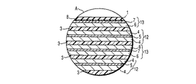
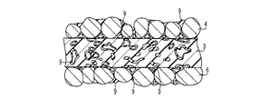
図1は、本発明に係わる第1の非水電解液二次電池の一例である薄型リチウムイオン二次電池を示す断面図、図2は図1のA部を示す拡大断面図、図3は図1の二次電池における正極層、セパレータ及び負極層の境界付近を示す模式図である。 FIG. 1 is a cross-sectional view showing a thin lithium ion secondary battery as an example of a first non-aqueous electrolyte secondary battery according to the present invention, FIG. 2 is an enlarged cross-sectional view showing part A of FIG. 1, and FIG. FIG. 2 is a schematic diagram showing the vicinity of a boundary between a positive electrode layer, a separator, and a negative electrode layer in the secondary battery of FIG. 1.
図1に示すように、例えばフィルムからなる外装材1は、電極群2を包囲している。前記電極群2は、正極、セパレータおよび負極からなる積層物が偏平形状に捲回された構造を有する。前記積層物は、図2に示すように、(図の下側から)セパレータ3、正極層4と正極集電体5と正極層4を備えた正極12、セパレータ3、負極層6と負極集電体7と負極層6を備えた負極13、セパレータ3、正極層4と正極集電体5と正極層4を備えた正極12、セパレータ3、負極層6と負極集電体7を備えた負極13がこの順番に積層されたものからなる。前記電極群2は、最外層に前記負極集電体7が位置している。前記電極群2の表面は、接着部8が存在している。前記外装材1の内面は、前記接着部8に接着されている。図3に示すように、正極層4、セパレータ3及び負極層6の空隙には、接着性を有する高分子9がそれぞれ保持されている。正極12及びセパレータ3は、正極層4及びセパレータ3の内部及びこれらの境界に点在する接着性を有する高分子9により接着されている。一方、負極13及びセパレータ3は、負極層6及びセパレータ3の内部及びこれらの境界に点在する接着性を有する高分子9により接着されている。非水電解液は、前記外装材1内の前記電極群2に含浸されている。帯状の正極リード10は、一端が前記電極群2の前記正極集電体5に接続され、かつ他端が前記外装材1から延出されている。一方、帯状の負極リード11は、一端が前記電極群2の前記負極集電体7に接続され、かつ他端が前記外装材1から延出されている。
As shown in FIG. 1, an exterior material 1 made of, for example, a film surrounds an electrode group 2. The electrode group 2 has a structure in which a laminate composed of a positive electrode, a separator, and a negative electrode is wound into a flat shape. As shown in FIG. 2, the laminate includes a
なお、前述した図1においては、電極群2の表面全体に接着部8を形成したが、電極群2の一部に接着部8を形成しても良い。電極群2の一部に接着部8を形成する場合、少なくとも電極群の最外周に相当する面に形成することが好ましい。また、接着部8はなくても良い。
In FIG. 1 described above, the
この前述した(a)の条件を満足する電極群を備える非水電解液二次電池は、例えば、以下に説明する(I)方法で製造される。ただし、本発明に係る非水電解液二次電池の製造方法は本発明の範囲にあるものであれば以下の形態に限定されるものではない。 The non-aqueous electrolyte secondary battery including the electrode group that satisfies the above-described condition (a) is manufactured by, for example, the method (I) described below. However, the manufacturing method of the non-aqueous electrolyte secondary battery according to the present invention is not limited to the following embodiment as long as it is within the scope of the present invention.
<製造方法(I)>
(第1工程)
正極及び負極の間にセパレータとして多孔質シートを介在させて電極群を作製する。
<Manufacturing method (I)>
(First step)
An electrode group is prepared by interposing a porous sheet as a separator between the positive electrode and the negative electrode.
前記電極群は、正極と負極をその間に接着性を有する高分子未保持のセパレータを介して渦巻き状に捲回するか、もしくは渦巻き状に捲回した後、径方向に圧縮するか、あるいは正極と負極をその間に接着性を有する高分子未保持のセパレータを介して複数回折り曲げることにより作製されることが望ましい。このような方法で作製すると、後述する第2工程において、正極、負極及びセパレータに接着性を有する高分子の溶液を浸透させつつ、正極とセパレータの境界及び負極とセパレータの境界全体に前記溶液が浸透するのを防止することができる。その結果、正極、負極及びセパレータに接着性を有する高分子を点在させることが可能になると共に、正極とセパレータの境界及び負極とセパレータの境界に接着性を有する高分子を点在させることができる。 In the electrode group, the positive electrode and the negative electrode are spirally wound through a separator having no polymer between them, or wound in a spiral shape and then compressed in the radial direction, or the positive electrode It is desirable that the negative electrode is fabricated by bending a plurality of times through a separator having no polymer between them and having an adhesive property therebetween. When produced by such a method, in the second step to be described later, while the polymer solution having adhesiveness is infiltrated into the positive electrode, the negative electrode, and the separator, the solution is applied to the entire boundary between the positive electrode and the separator and between the negative electrode and the separator. Infiltration can be prevented. As a result, it is possible to intersperse the polymer having adhesiveness to the positive electrode, the negative electrode and the separator, and to interpose the polymer having adhesiveness to the boundary between the positive electrode and the separator and the boundary between the negative electrode and the separator. it can.
前記正極は、例えば、正極活物質に導電剤および結着剤を適当な溶媒に懸濁し、この懸濁物を集電体に塗布、乾燥して薄板状にすることにより作製される。前記正極活物質、導電剤、結着剤及び集電体としては、前述した(1)正極の欄で説明したのと同様なものを挙げることができる。 The positive electrode is produced, for example, by suspending a conductive agent and a binder in an appropriate solvent in a positive electrode active material, applying the suspension to a current collector, and drying to form a thin plate. Examples of the positive electrode active material, the conductive agent, the binder, and the current collector include the same materials as those described in the section of (1) Positive electrode described above.
前記負極は、例えば、リチウムイオンを吸蔵・放出する炭素質物と結着剤とを溶媒の存在下で混練し、得られた懸濁物を集電体に塗布し、乾燥した後、所望の圧力で1回プレスもしくは2〜5回多段階プレスすることにより作製される。 The negative electrode is, for example, kneaded with a carbonaceous material that occludes / releases lithium ions and a binder in the presence of a solvent, and the resulting suspension is applied to a current collector and dried, followed by a desired pressure. It is produced by pressing once or multistage pressing 2-5 times.
前記炭素質物、結着剤及び集電体としては、前述した(2)負極の欄で説明したのと同様なものを挙げることができる。 Examples of the carbonaceous material, the binder, and the current collector include the same materials as those described in the section of (2) Negative electrode.
前記セパレータの多孔質シートとしては、前述した(3)セパレータの欄で説明したのと同様なものを用いることができる。 As the porous sheet of the separator, the same sheet as described in the section of (3) Separator described above can be used.
(第2工程)
袋状に加工された外装材内に前記電極群を積層面が開口部から見えるように収納する。溶媒に接着性を有する高分子を溶解させることにより得られた溶液を開口部から前記外装材内の電極群に注入し、前記溶液を前記電極群に含浸させる。
(Second step)
The electrode group is accommodated in a bag-shaped exterior material so that the laminated surface can be seen from the opening. A solution obtained by dissolving a polymer having adhesiveness in a solvent is injected into the electrode group in the exterior material from the opening, and the electrode group is impregnated with the solution.
前記外装材しては、前述した(6)外装材の欄で説明したのと同様なものを挙げることができる。 Examples of the exterior material include the same materials as those described in the section of (6) Exterior material described above.
前記接着性を有する高分子としては、前述した(5)の接着性を有する高分子の欄で説明したのと同様なものを挙げることができる。特に、PVdFが好ましい。 Examples of the adhesive polymer include the same polymers as described in the column of the adhesive polymer (5) described above. In particular, PVdF is preferable.
前記溶媒には、沸点が200℃以下の有機溶媒を用いることが望ましい。かかる有機溶媒としは、例えば、ジメチルフォルムアミド(沸点153℃)を挙げることができる。有機溶媒の沸点が200℃を越えると、後述する真空乾燥の温度を100℃以下にした際、乾燥時間が長く掛かる恐れがある。また、有機溶媒の沸点の下限値は、50℃にすることが好ましい。有機溶媒の沸点を50℃未満にすると、前記溶液を電極群に注入している間に前記有機溶媒が蒸発してしまう恐れがある。沸点の上限値は、180℃にすることがさらに好ましく、また、沸点の下限値は100℃にすることがさらに好ましい。 As the solvent, it is desirable to use an organic solvent having a boiling point of 200 ° C. or lower. An example of such an organic solvent is dimethylformamide (boiling point 153 ° C.). If the boiling point of the organic solvent exceeds 200 ° C., the drying time may take a long time when the vacuum drying temperature described below is set to 100 ° C. or lower. The lower limit of the boiling point of the organic solvent is preferably 50 ° C. If the boiling point of the organic solvent is less than 50 ° C., the organic solvent may evaporate while the solution is injected into the electrode group. The upper limit of the boiling point is more preferably 180 ° C., and the lower limit of the boiling point is further preferably 100 ° C.
前記溶液中の接着性を有する高分子の濃度は、0.05〜2.5重量%の範囲にすることが好ましい。これは次のような理由によるものである。前記濃度を0.05重量%未満にすると、正負極及びセパレータを十分な強度で接着することが困難になる恐れがある。一方、前記濃度が2.5重量%を越えると、非水電解液を保持できるだけの十分な多孔度を得ることが困難になって電極の界面インピーダンスが著しく大きくなる恐れがある。界面インピーダンスが増大すると、容量及び大電流放電特性が大幅に低下する。濃度のより好ましい範囲は、0.1〜1.5重量%である。 The concentration of the polymer having adhesiveness in the solution is preferably in the range of 0.05 to 2.5% by weight. This is due to the following reason. If the concentration is less than 0.05% by weight, it may be difficult to bond the positive and negative electrodes and the separator with sufficient strength. On the other hand, if the concentration exceeds 2.5% by weight, it may be difficult to obtain a sufficient porosity to hold the non-aqueous electrolyte, and the interface impedance of the electrode may be significantly increased. As the interfacial impedance increases, the capacity and large current discharge characteristics are significantly reduced. A more preferable range of the concentration is 0.1 to 1.5% by weight.
前記溶液の注入量は、前記溶液の接着性を有する高分子の濃度が0.05〜2.5重量%である場合、電池容量100mAh当たり0.1〜2mlの範囲にすることが好ましい。これは次のような理由によるものである。前記注入量を0.1ml未満にすると、正極、負極及びセパレータの密着性を十分に高めることが困難になる恐れがある。一方、前記注入量が2mlを越えると、二次電池のリチウムイオン伝導度の低下や、内部抵抗の上昇を招く恐れがあり、放電容量、大電流放電特性及び充放電サイクル特性を改善することが困難になる恐れがある。前記注入量のより好ましい範囲は、電池容量100mAh当たり0.15〜1mlである。 The amount of the solution injected is preferably in the range of 0.1 to 2 ml per 100 mAh of battery capacity when the concentration of the polymer having adhesiveness in the solution is 0.05 to 2.5% by weight. This is due to the following reason. If the injection amount is less than 0.1 ml, it may be difficult to sufficiently improve the adhesion between the positive electrode, the negative electrode, and the separator. On the other hand, if the injection amount exceeds 2 ml, the lithium ion conductivity of the secondary battery may be decreased and the internal resistance may be increased, which may improve the discharge capacity, large current discharge characteristics, and charge / discharge cycle characteristics. It can be difficult. A more preferable range of the injection amount is 0.15 to 1 ml per 100 mAh of battery capacity.
(第3工程)
前記電極群に真空乾燥を施すことにより前記溶液中の溶媒を蒸発させ、前記正極、負極及びセパレータの空隙内に接着性を有する高分子を存在せしめる。この工程により、前記正極と前記セパレータがこれらの内部及び境界に点在する接着性を有する高分子により接着されると共に、前記負極と前記セパレータがこれらの内部及び境界に点在する接着性を有する高分子により接着される。また、この真空乾燥により前記電極群中に含まれる水分の除去を同時に行うことができる。
(Third step)
By subjecting the electrode group to vacuum drying, the solvent in the solution is evaporated, and an adhesive polymer is present in the gaps of the positive electrode, the negative electrode, and the separator. By this step, the positive electrode and the separator are adhered by a polymer having adhesiveness scattered in the inside and the boundary thereof, and the negative electrode and the separator have adhesiveness scattered in the interior and the boundary thereof. Bonded by polymer. Moreover, the moisture contained in the electrode group can be removed simultaneously by this vacuum drying.
なお、前記電極群は、微量の溶媒を含むことを許容する。 In addition, the said electrode group accept | permits containing a trace amount solvent.
前記真空乾燥は、100℃以下で行うことが好ましい。これは次のような理由によるものである。真空乾燥の温度が100℃を越えると、前記セパレータが大幅に熱収縮する恐れがある。熱収縮が大きくなると、セパレータが反るため、正極、負極及びセパレータを強固に接着することが困難になる。また、前述した熱収縮は、ポリエチレンまたはポリプロピレンを含む多孔質フィルムをセパレータとして用いる場合に顕著に生じやすい。真空乾燥の温度が低くなるほどセパレータの熱収縮を抑制できるものの、真空乾燥の温度を40℃未満にすると、十分に溶媒を蒸発させることが困難になる恐れがある。このため、真空乾燥温度は、40〜100℃にすることがより好ましい。 The vacuum drying is preferably performed at 100 ° C. or lower. This is due to the following reason. When the temperature of vacuum drying exceeds 100 ° C., the separator may be significantly heat-shrinked. When the thermal shrinkage increases, the separator warps, and it becomes difficult to firmly bond the positive electrode, the negative electrode, and the separator. In addition, the above-described heat shrinkage tends to occur remarkably when a porous film containing polyethylene or polypropylene is used as a separator. Although the thermal shrinkage of the separator can be suppressed as the vacuum drying temperature becomes lower, if the temperature of the vacuum drying is lower than 40 ° C., it may be difficult to sufficiently evaporate the solvent. For this reason, it is more preferable that the vacuum drying temperature is 40 to 100 ° C.
(第4工程)
前記外装材内の電極群に非水電解液を注入した後、前記外装材の開口部を封止することにより薄型非水電解液二次電池を組み立てる。
(4th process)
After injecting a non-aqueous electrolyte into the electrode group in the exterior material, a thin non-aqueous electrolyte secondary battery is assembled by sealing the opening of the exterior material.
前記非水電解液としては、前述した(4)非水電解液の欄で説明したものと同様なものを用いることができる。 As said non-aqueous electrolyte, the thing similar to what was demonstrated in the column of (4) non-aqueous electrolyte mentioned above can be used.
前述した製造方法においては、接着性を有する高分子が溶解された溶液の注入を外装材に電極群を収納してから行ったが、外装材に収納せずに注入を行っても良い。この場合、まず、正極と負極の間にセパレータを介在させて電極群を作製する。前記電極群に前記溶液を含浸させた後、前記電極群に真空乾燥を施すことにより前記溶液の溶媒を蒸発させ、前記正極、負極及びセパレータの空隙内に接着性を有する高分子を存在せしめる。このような電極群を外装材に収納した後、非水電解液を注入し、封口等を行うことにより薄型の非水電解液二次電池を製造することができる。外装材への収納前に電極群外周に接着剤を塗布してもよい。それにより外装材に電極群を接着することができる。また、この場合、外装材としてフィルムの代わりに金属缶を用いることができる。 In the manufacturing method described above, the solution in which the adhesive polymer is dissolved is injected after the electrode group is stored in the exterior material. However, the injection may be performed without being stored in the exterior material. In this case, first, an electrode group is produced by interposing a separator between the positive electrode and the negative electrode. After the electrode group is impregnated with the solution, the electrode group is vacuum-dried to evaporate the solvent of the solution, and the adhesive polymer is present in the gaps of the positive electrode, the negative electrode, and the separator. A thin non-aqueous electrolyte secondary battery can be manufactured by injecting such a group of electrodes into an exterior material, then injecting a non-aqueous electrolyte and performing sealing or the like. You may apply | coat an adhesive agent to the electrode group outer periphery before the accommodation to an exterior material. Thereby, an electrode group can be adhere | attached on an exterior material. In this case, a metal can can be used as an exterior material instead of a film.
(第5工程)
上記の如くに組み立てた二次電池に30℃〜80℃の温度条件下で、0.05C以上、0.5C以下の充電レートで初充電を施す。この条件での充電は1サイクルのみでも良いし、2サイクル以上行ってもよい。また、初充電前に30℃〜80℃の温度条件下に1時間〜20時間程度保管してもよい。
(5th process)
The secondary battery assembled as described above is initially charged at a charge rate of 0.05 C or more and 0.5 C or less under a temperature condition of 30 ° C. to 80 ° C. Charging under this condition may be performed only for one cycle or may be performed for two or more cycles. Moreover, you may store for about 1 hour-20 hours on 30 degreeC-80 degreeC temperature conditions before the first charge.
ここで、1C充電レートとは公称容量(Ah)を1時間で充電するために必要な電流値である。 Here, the 1C charging rate is a current value necessary for charging the nominal capacity (Ah) in one hour.
前記初充電の温度を前記範囲に規定するのは次のような理由によるものである。初充電温度が30℃未満であると、非水電解液の粘度が高いままであるために非水電解液を正極、負極及びセパレータに均一に含浸させることが困難になり、内部インピーダンスが増加し、また活物質の利用率が低下する。一方、初充電温度が80℃を超えると、正極及び負極に含まれる結着剤が劣化する。 The reason for defining the initial charging temperature within the above range is as follows. If the initial charging temperature is less than 30 ° C., the viscosity of the nonaqueous electrolyte solution remains high, so that it is difficult to uniformly impregnate the nonaqueous electrolyte solution in the positive electrode, negative electrode, and separator, and the internal impedance increases. Moreover, the utilization factor of an active material falls. On the other hand, when the initial charging temperature exceeds 80 ° C., the binder contained in the positive electrode and the negative electrode is deteriorated.
初充電の充電レートを0.05〜0.5Cの範囲にすることによって、充電による正極と負極の膨張を適度に遅くすることができるため、正極及び負極に非水電解液を均一に浸透させることができる。 By making the charge rate of the initial charge in the range of 0.05 to 0.5 C, the expansion of the positive electrode and the negative electrode due to the charge can be moderately slowed, so that the nonaqueous electrolyte uniformly penetrates the positive electrode and the negative electrode be able to.
このような工程を具備することによって、電極やセパレータの空隙に非水電解液を均一に含浸させることができるため、非水電解液二次電池の1kHzの内部インピーダンスを小さくすることができ、電池容量と1kHzの内部インピーダンスの積を10mΩ・Ah以上110mΩ・Ah以下の範囲にすることができる。その結果、活物質の利用率を増大させることができるため、実質的な電池の容量を大きくすることができる。また、電池の充放電サイクル特性及び大電流放電特性を向上させることができる。 By providing such a process, the non-aqueous electrolyte can be uniformly impregnated in the gaps of the electrodes and the separator, so that the internal impedance of 1 kHz of the non-aqueous electrolyte secondary battery can be reduced. The product of the capacity and the internal impedance of 1 kHz can be in the range of 10 mΩ · Ah to 110 mΩ · Ah. As a result, since the utilization factor of the active material can be increased, the substantial capacity of the battery can be increased. Moreover, the charge / discharge cycle characteristics and the large current discharge characteristics of the battery can be improved.
次いで、前述した(b)を満足する電極群と、前述した50体積%より多く、95体積%以下のγ−ブチロラクトンを含む非水溶媒を含有した非水電解液を備える非水電解液二次電池について説明する。 Next, a non-aqueous electrolyte secondary comprising an electrode group satisfying the above-mentioned (b) and a non-aqueous electrolyte containing a non-aqueous solvent containing γ-butyrolactone in an amount of more than 50% by volume and not more than 95% by volume. The battery will be described.
この二次電池においては、前記正極、前記負極及び前記セパレータが、前記正極及び前記負極に含まれる結着剤を熱硬化させることにより一体化されている。 In this secondary battery, the positive electrode, the negative electrode, and the separator are integrated by thermosetting the binder contained in the positive electrode and the negative electrode.
前記セパレータとしては、前述した(3)セパレータの欄で説明したのと同様なものが用いられる。また、前記電極群を収納する外装材としては、前述した(6)外装材の欄で説明したのと同様なものが用いられる。 As the separator, the same separator as described in the section of (3) Separator described above is used. Moreover, as an exterior material which accommodates the said electrode group, the thing similar to what was demonstrated in the column of (6) exterior material mentioned above is used.
前記正極は、活物質、結着剤及び導電剤を含む正極層が集電体の片面もしくは両面に担持された構造を有する。前記活物質、結着剤、導電剤及び集電体としては、前述した(1)正極の欄で説明したのと同様なものが用いられる。 The positive electrode has a structure in which a positive electrode layer containing an active material, a binder, and a conductive agent is supported on one side or both sides of a current collector. As the active material, the binder, the conductive agent, and the current collector, the same materials as those described in the section of (1) Positive electrode described above are used.
前記負極は、リチウムイオンを吸蔵・放出する炭素質物及び結着剤を含む負極層が集電体の片面もしくは両面に担持された構造を有する。前記炭素質物、結着剤及び集電体としては、前述した(2)負極の欄で説明したのと同様なものが用いられる。 The negative electrode has a structure in which a negative electrode layer containing a carbonaceous material that occludes / releases lithium ions and a binder is supported on one side or both sides of a current collector. As the carbonaceous material, the binder, and the current collector, the same materials as those described in the section of (2) Negative electrode are used.
前記負極層は、前述したリチウムイオンを吸蔵・放出する炭素物質を含むものの他に、アルミニウム、マグネシウム、スズ、けい素等の金属か、金属酸化物か、金属硫化物か、もしくは金属窒化物から選ばれる金属化合物や、リチウム合金を含むものであってもよい。前記金属酸化物、前記金属硫化物、前記金属窒化物及び前記リチウム合金としては、前述した(2)負極の欄で説明したのと同様なものが用いられる。 The negative electrode layer is made of a metal such as aluminum, magnesium, tin, or silicon, a metal oxide, a metal sulfide, or a metal nitride, in addition to the carbon material that absorbs and releases lithium ions. It may contain a selected metal compound or lithium alloy. As the metal oxide, the metal sulfide, the metal nitride, and the lithium alloy, the same materials as those described in the section of (2) Negative electrode are used.
この二次電池は、例えば、以下に説明する方法(II)で製造される。 This secondary battery is manufactured by, for example, the method (II) described below.
<製造方法(II)>
(第1工程)
以下の(a)〜(c)に説明する方法により電極群を作製する。
<Production method (II)>
(First step)
An electrode group is produced by the method described in the following (a) to (c).
(a)正極及び負極をその間にセパレータを介在させて渦巻き状に捲回する。 (A) The positive electrode and the negative electrode are wound spirally with a separator interposed therebetween.
(b)正極及び負極をその間にセパレータを介在させて渦巻き状に捲回した後、径方向に圧縮する。 (B) The positive electrode and the negative electrode are wound spirally with a separator interposed therebetween, and then compressed in the radial direction.
(c)正極及び負極をその間にセパレータを介在させて2回以上折り曲げる。 (C) The positive electrode and the negative electrode are bent twice or more with a separator interposed therebetween.
(第2工程)
袋状のフィルム製外装材内に前記電極群を収納する。
(Second step)
The electrode group is housed in a bag-shaped film exterior material.
(第3工程)
前記電極群を40〜120℃に加熱しながら成形する。
(Third step)
The electrode group is molded while being heated to 40 to 120 ° C.
前記成形は、前記電極群が前記(a)の方法で作製される場合には径方向に、前記電極群が前記(b)または(c)の方法で作製される場合には積層方向に圧縮されるように行う。 The molding is compressed in the radial direction when the electrode group is produced by the method (a), and compressed in the laminating direction when the electrode group is produced by the method (b) or (c). To be done.
前記成形は、例えば、プレス成形、あるいは成形型への填め込み等により行うことができる。 The molding can be performed, for example, by press molding or insertion into a mold.
電極群の成形を行う際に前記電極群の加熱を行う理由を説明する。前記電極群には接着性を有する高分子が含まれていない。このため、この電極群に常温で成形を行うと、成形後にスプリングバックが生じる、つまり正極とセパレータ、及び負極とセパレータの間に隙間が生じる。その結果、正極とセパレータの接触面積及び負極とセパレータの接触面積が低下するため、内部インピーダンスが大きくなる。前記電極群に40℃以上で成形を行うことによって、正極及び負極に含まれる結着剤を熱硬化させることができるため、電極群の硬度を高めることができる。その結果、成形後のスプリングバックを抑制することができるため、正極とセパレータの接触面積及び負極とセパレータの接触面積を向上することができ、その接触面積を充放電サイクルを繰り返しても維持することができる。一方、前記電極群の温度が120℃を超えると、セパレータが大幅に熱収縮する恐れがある。より好ましい温度は、60〜100℃である。 The reason why the electrode group is heated when forming the electrode group will be described. The electrode group does not contain an adhesive polymer. For this reason, when this electrode group is molded at room temperature, springback occurs after molding, that is, gaps are formed between the positive electrode and the separator and between the negative electrode and the separator. As a result, the contact area between the positive electrode and the separator and the contact area between the negative electrode and the separator are reduced, so that the internal impedance is increased. By forming the electrode group at 40 ° C. or higher, the binder contained in the positive electrode and the negative electrode can be thermally cured, so that the hardness of the electrode group can be increased. As a result, since the spring back after molding can be suppressed, the contact area between the positive electrode and the separator and the contact area between the negative electrode and the separator can be improved, and the contact area can be maintained even after repeated charge / discharge cycles. Can do. On the other hand, when the temperature of the electrode group exceeds 120 ° C., the separator may be significantly heat-shrinked. A more preferable temperature is 60 to 100 ° C.
前述した特定温度に加熱しながらの成形は、例えば、常圧下、もしくは減圧下、あるいは真空下で行うことができる。減圧下、あるいは真空下で行うと、電極群からの水分除去効率が向上されるため、望ましい。 The molding while heating to the specific temperature described above can be performed, for example, under normal pressure, under reduced pressure, or under vacuum. It is desirable to perform under reduced pressure or under vacuum because the water removal efficiency from the electrode group is improved.
前記成形をプレス成形により行う場合、プレス圧は、0.01〜20kg/cm2の範囲にすることが好ましい。これは次のような理由によるものである。プレス圧を0.01kg/cm2より低くすると、成形後のスプリングバックを抑制することが困難になる恐れがある。一方、プレス圧が20kg/cm2より高いと、電極群中の空隙率が低下する恐れがあるため、電極群の非水電解液保持量が不足する恐れがある。 When the molding is performed by press molding, the pressing pressure is preferably in the range of 0.01 to 20 kg / cm 2 . This is due to the following reason. If the pressing pressure is lower than 0.01 kg / cm 2, it may be difficult to suppress the spring back after molding. On the other hand, if the press pressure is higher than 20 kg / cm 2 , the porosity in the electrode group may be reduced, and therefore the amount of nonaqueous electrolyte retained in the electrode group may be insufficient.
(第4工程)
前記外装材内の電極群に非水電解液を注入した後、前記外装材の開口部を封止することにより前述した非水電解液二次電池を組み立てる。
(4th process)
After injecting a nonaqueous electrolyte into the electrode group in the exterior material, the nonaqueous electrolyte secondary battery described above is assembled by sealing the opening of the exterior material.
前述した製造方法においては、外装材に電極群を収納してから電極群を特定温度に加熱しつつ成形したが、外装材に収納する前に前述した加熱成形を行っても良い。この場合、まず、前述した第1の工程により電極群を作製する。前記電極群を40〜120℃に加熱しながら成形する。次いで、前記電極群を外装材に収納した後、非水電解液を注入し、封口等を行うことにより前述した非水電解液二次電池を組み立てることができる。このとき、外装材としてフィルムの代わりに金属缶を用いることができる。 In the manufacturing method described above, the electrode group is housed in the exterior material and then molded while heating the electrode group to a specific temperature. However, the heat molding described above may be performed before housing in the exterior material. In this case, first, an electrode group is fabricated by the first process described above. The electrode group is molded while being heated to 40 to 120 ° C. Next, after the electrode group is housed in an exterior material, the nonaqueous electrolyte secondary battery described above can be assembled by injecting a nonaqueous electrolyte and performing sealing or the like. At this time, a metal can can be used as an exterior material instead of a film.
(第5工程)
上記の如くに組み立てた二次電池に30℃〜80℃の温度条件下で、0.05C以上、0.5C以下の充電レートで初充電を施す。この条件での充電は1サイクルのみでも良いし、2サイクル以上行ってもよい。また、初充電前に30℃〜80℃の温度条件下に1時間〜20時間程度保管してもよい。
(5th process)
The secondary battery assembled as described above is initially charged at a charge rate of 0.05 C or more and 0.5 C or less under a temperature condition of 30 ° C. to 80 ° C. Charging under this condition may be performed only for one cycle or may be performed for two or more cycles. Moreover, you may store for about 1 hour-20 hours on 30 degreeC-80 degreeC temperature conditions before the first charge.
前記初充電の温度及び初充電の充電レートを前記範囲に規定するのは、前述したのと同様な理由によるものである。 The reason why the temperature of the initial charge and the charge rate of the initial charge are defined in the range is for the same reason as described above.
このような工程を具備することによって、電極やセパレータの空隙に非水電解液を均一に含浸させることができるため、非水電解液二次電池の1kHzの内部インピーダンスを小さくすることができ、電池容量と1kHzの内部インピーダンスの積を10mΩ・Ah以上110mΩ・Ah以下の範囲にすることができる。その結果、活物質の利用率を増大させることができるため、実質的な電池の容量を大きくすることができる。また、電池の充放電サイクル特性及び大電流放電特性を向上させることができる。 By providing such a process, the non-aqueous electrolyte can be uniformly impregnated in the gaps of the electrodes and the separator, so that the internal impedance of 1 kHz of the non-aqueous electrolyte secondary battery can be reduced. The product of the capacity and the internal impedance of 1 kHz can be in the range of 10 mΩ · Ah to 110 mΩ · Ah. As a result, since the utilization factor of the active material can be increased, the substantial capacity of the battery can be increased. Moreover, the charge / discharge cycle characteristics and the large current discharge characteristics of the battery can be improved.
なお、本発明に係る第1の非水電解液二次電池においては、外装材としてアルミニウムなどからなる缶を用い、正極、負極及びセパレータからなる電極群を捲回し缶に挿入した構造であってもよい。その場合、接着部あるいは接着性を有する高分子はなくとも良い。 The first nonaqueous electrolyte secondary battery according to the present invention has a structure in which a can made of aluminum or the like is used as an exterior material, and an electrode group consisting of a positive electrode, a negative electrode, and a separator is wound and inserted into the can. Also good. In that case, there is no need for an adhesive part or a polymer having adhesiveness.
次いで、本発明に係る第2の非水電解液二次電池について説明する。 Next, the second nonaqueous electrolyte secondary battery according to the present invention will be described.
この二次電池は、正極集電体、及び前記正極集電体の片面もしくは両面に担持される正極活物質層を含む正極と、負極集電体、及び前記負極集電体の片面もしくは両面に担持され、リチウムイオンを吸蔵・放出する材料を含む負極活物質層を含む負極と、前記正極及び前記負極の間に配置されるセパレータとを備える電極群;
前記電極群に含浸され、非水溶媒と、前記非水溶媒に溶解されるリチウム塩とを含む非水電解液;
前記電極群が収納される外装材;を具備する。
The secondary battery includes a positive electrode current collector and a positive electrode including a positive electrode active material layer carried on one or both surfaces of the positive electrode current collector, a negative electrode current collector, and one or both surfaces of the negative electrode current collector. An electrode group including a negative electrode including a negative electrode active material layer that is supported and includes a material that absorbs and releases lithium ions; and a separator disposed between the positive electrode and the negative electrode;
A non-aqueous electrolyte solution impregnated in the electrode group and comprising a non-aqueous solvent and a lithium salt dissolved in the non-aqueous solvent;
An exterior material in which the electrode group is housed.
前記正極活物質層の空隙率は、前記負極活物質層の空隙率に比べて低い。また、前記正極活物質層の厚さは10〜100μmである。さらに、前記非水溶媒は、γ−ブチロラクトンを非水溶媒全体の40体積%以上95体積%以下含有する。 The porosity of the positive electrode active material layer is lower than the porosity of the negative electrode active material layer. The positive electrode active material layer has a thickness of 10 to 100 μm. Further, the non-aqueous solvent contains γ-butyrolactone in an amount of 40% by volume to 95% by volume based on the total amount of the non-aqueous solvent.
この二次電池は、前記正極、前記負極及び前記セパレータが一体化されていなくても良いが、以下の(a)、または(b)に説明するような条件で一体化されていることが好ましい。 In this secondary battery, the positive electrode, the negative electrode, and the separator do not have to be integrated, but it is preferable that they are integrated under the conditions described in (a) or (b) below. .
(a)前記正極及び前記セパレータがこれらの境界の少なくとも一部に存在する接着性を有する高分子により一体化されていると共に、前記負極及び前記セパレータがこれらの境界の少なくとも一部に存在する接着性を有する高分子により一体化されている。特に、前記正極及び前記セパレータがこれらの内部及び境界に点在する接着性を有する高分子により一体化されていると共に、前記負極及び前記セパレータがこれらの内部及び境界に点在する接着性を有する高分子により一体化されていることが望ましい。 (A) Adhesion in which the positive electrode and the separator are integrated by an adhesive polymer present at at least a part of these boundaries, and the negative electrode and the separator are present at at least a part of these boundaries It is integrated with a polymer having properties. In particular, the positive electrode and the separator are integrated with an adhesive polymer scattered in the interior and boundary thereof, and the negative electrode and the separator have adhesiveness scattered in the interior and boundary thereof. It is desirable that they are integrated by a polymer.
(b)前記正極、前記負極及び前記セパレータが、前記正極及び前記負極に含まれる結着剤を熱硬化させることにより一体化されている。 (B) The positive electrode, the negative electrode, and the separator are integrated by thermosetting the binder contained in the positive electrode and the negative electrode.
この(a)または(b)の構成にすることによって、外装材の膨れをより一層低減することができる。 By adopting the configuration of (a) or (b), the swelling of the exterior material can be further reduced.
また、前記二次電池は、電池容量(Ah)と1kHzの電池内部インピーダンス(mΩ)の積が10mΩ・Ah以上、110mΩ・Ah以下であることが望ましい。容量とインピーダンスの積を前記範囲内にすることによって、大電流放電特性と充放電サイクル特性をより向上することができる。ここで、電池容量とは、公称容量あるいは0.2Cで放電した際の放電容量である。より好ましい範囲は、20mΩ・Ah以上、60mΩ・Ah以下である。 The secondary battery preferably has a product of battery capacity (Ah) and 1 kHz battery internal impedance (mΩ) of 10 mΩ · Ah or more and 110 mΩ · Ah or less. By setting the product of the capacity and the impedance within the above range, the large current discharge characteristics and the charge / discharge cycle characteristics can be further improved. Here, the battery capacity is a nominal capacity or a discharge capacity when discharged at 0.2C. A more preferable range is 20 mΩ · Ah or more and 60 mΩ · Ah or less.
電池容量とインピーダンスの積を10mΩ・Ah以上、110mΩ・Ah以下にするのは、例えば、前述した(I)の製造方法か、あるいは前述した(II)の製造方法により可能である。但し、(I)において、接着性高分子の添加量、接着性高分子の分布及び初充電条件を、電池容量とインピーダンスの積が10mΩ・Ah以上、110mΩ・Ah以下になるように設定する。また、(II)においては、電極群を成形する際の温度とプレス圧、及び初充電条件を、電池容量とインピーダンスの積が10mΩ・Ah以上、110mΩ・Ah以下になるように設定する。 The product of the battery capacity and the impedance can be 10 mΩ · Ah or more and 110 mΩ · Ah or less, for example, by the manufacturing method (I) described above or the manufacturing method (II) described above. However, in (I), the addition amount of the adhesive polymer, the distribution of the adhesive polymer, and the initial charging conditions are set so that the product of the battery capacity and the impedance is 10 mΩ · Ah or more and 110 mΩ · Ah or less. In (II), the temperature, press pressure, and initial charge condition when forming the electrode group are set so that the product of the battery capacity and impedance is 10 mΩ · Ah or more and 110 mΩ · Ah or less.
以下、前述した(a)を満足する電極群を備える非水電解液二次電池について説明する。 Hereinafter, a non-aqueous electrolyte secondary battery including an electrode group that satisfies the above-described (a) will be described.
1)正極
この正極は、活物質、導電剤、接着性を有する高分子及び結着剤を含む正極活物質層が集電体の片面もしくは両面に担持された構造を有する。
1) Positive Electrode This positive electrode has a structure in which a positive electrode active material layer including an active material, a conductive agent, an adhesive polymer, and a binder is supported on one side or both sides of a current collector.
前記活物質、導電剤、接着性を有する高分子及び結着剤としては、前述した第1の非水電解液二次電池で説明したのと同様なものを挙げることができる。 Examples of the active material, the conductive agent, the adhesive polymer, and the binder include the same materials as those described in the first non-aqueous electrolyte secondary battery.
前記正極活物質層の厚さは、10〜100μmの範囲にする。ここで、正極活物質層の厚さとは、セパレータと対向する正極活物質表面と集電体と接する正極活物質表面との距離を意味する。例えば、図4に示すように、集電体Sの両面に正極活物質層Pが担持されている場合、セパレータと対向する正極活物質表面P1と集電体と接する正極活物質表面P2との距離が正極活物質層の厚さTである。従って、正極集電体の両面に正極活物質層が担持されている場合、正極活物質層の片面の厚さが10〜100μmで、正極活物質層の合計厚さが20〜200μmの範囲となる。正極活物質層の厚さを10μm未満にすると、集電体重量比率と体積比率が高くなるため、エネルギー密度が低下する。厚さの好ましい下限値は、30μmで、更に好ましい下限値は50μmである。一方、正極活物質層の厚さが100μmを超えると、急速充放電サイクル時に非水電解液が正極表面に集中し、正極内部における電極反応がほとんど進行しなくなるため、サイクル寿命が低下する。厚さの好ましい上限値は85μmで、更に好ましい上限値は60μmである。特に、正極活物質層の厚さは、10〜60μmの範囲にすることが好ましい。この範囲内であると、大電流放電特性とサイクル寿命が大幅に向上する。更に好ましい範囲は、30〜50μmである。 The positive electrode active material layer has a thickness in the range of 10 to 100 μm. Here, the thickness of the positive electrode active material layer means the distance between the surface of the positive electrode active material facing the separator and the surface of the positive electrode active material in contact with the current collector. For example, as shown in FIG. 4, when the positive electrode active material layer P is supported on both surfaces of the current collector S, the positive electrode active material surface P 1 facing the separator and the positive electrode active material surface P 2 in contact with the current collector Is the thickness T of the positive electrode active material layer. Therefore, when the positive electrode active material layer is supported on both surfaces of the positive electrode current collector, the thickness of one surface of the positive electrode active material layer is 10 to 100 μm and the total thickness of the positive electrode active material layer is 20 to 200 μm. Become. When the thickness of the positive electrode active material layer is less than 10 μm, the weight ratio of the current collector and the volume ratio are increased, so that the energy density is decreased. A preferable lower limit of the thickness is 30 μm, and a more preferable lower limit is 50 μm. On the other hand, when the thickness of the positive electrode active material layer exceeds 100 μm, the non-aqueous electrolyte concentrates on the positive electrode surface during the rapid charge / discharge cycle, and the electrode reaction inside the positive electrode hardly progresses, so that the cycle life is reduced. A preferable upper limit value of the thickness is 85 μm, and a more preferable upper limit value is 60 μm. In particular, the thickness of the positive electrode active material layer is preferably in the range of 10 to 60 μm. Within this range, the large current discharge characteristics and cycle life are greatly improved. A more preferable range is 30 to 50 μm.
前記正極活物質層の厚さは、以下に説明する方法で測定される。まず、互いに1cm以上離れて存在する10点を任意に選択し、各点の厚さを測定し、その平均値を算出することにより正極の厚さを測定する。但し、測定しようとしている正極が、集電体の両面に正極活物質層が担持された構造を有する場合には、片方の正極活物質層を除去してから正極の厚さを測定する。次いで、集電体から正極活物質層を除去し、集電体の厚さを測定する。集電体の厚さは、互いに1cm以上離れて存在する10点を任意に選択し、各点の厚さを測定し、その平均値を算出することにより求められる。前記正極の厚さと前記集電体の厚さの差を、求める正極活物質層の厚さとする。 The thickness of the positive electrode active material layer is measured by the method described below. First, 10 points that are separated from each other by 1 cm or more are arbitrarily selected, the thickness of each point is measured, and the average value is calculated to measure the thickness of the positive electrode. However, when the positive electrode to be measured has a structure in which the positive electrode active material layer is supported on both sides of the current collector, the thickness of the positive electrode is measured after removing one of the positive electrode active material layers. Next, the positive electrode active material layer is removed from the current collector, and the thickness of the current collector is measured. The thickness of the current collector can be obtained by arbitrarily selecting 10 points that are separated from each other by 1 cm or more, measuring the thickness of each point, and calculating the average value. The difference between the thickness of the positive electrode and the thickness of the current collector is taken as the thickness of the positive electrode active material layer to be obtained.
前記正極活物質層の空隙率は、前記負極活物質層の空隙率に比べて低い。前記正極活物質層の空隙率は、25〜40%の範囲にすることが好ましい。これは次のような理由によるものである。空隙率を25%未満にすると、正極活物質層の厚さを規制していても非水電解液を均一に浸透させることが困難になる恐れがある。一方、空隙率が40%を超えると、高容量、つまり高エネルギー密度を得られなくなる恐れがある。空隙率のより好ましい範囲は、30〜35%である。 The porosity of the positive electrode active material layer is lower than the porosity of the negative electrode active material layer. The porosity of the positive electrode active material layer is preferably in the range of 25 to 40%. This is due to the following reason. If the porosity is less than 25%, it may be difficult to uniformly infiltrate the non-aqueous electrolyte even if the thickness of the positive electrode active material layer is regulated. On the other hand, if the porosity exceeds 40%, a high capacity, that is, a high energy density may not be obtained. A more preferable range of the porosity is 30 to 35%.
前記集電体としては、多孔質構造の導電性基板か、あるいは無孔の導電性基板を用いることができる。これら導電性基板は、例えば、アルミニウム、ステンレス、またはニッケルから形成することができる。集電体の厚さは、5〜20μmの範囲にすることが好ましい。この範囲内であると、正極強度と軽量化のバランスがとれるからである。 As the current collector, a conductive substrate having a porous structure or a non-porous conductive substrate can be used. These conductive substrates can be formed from, for example, aluminum, stainless steel, or nickel. The thickness of the current collector is preferably in the range of 5 to 20 μm. This is because within this range, the balance between the positive electrode strength and the weight reduction can be achieved.
2)負極
この負極は、リチウムイオンを吸蔵・放出する炭素質物、接着性を有する高分子及び結着剤を含む負極活物質層が集電体の片面もしくは両面に担持された構造を有する。
2) Negative electrode This negative electrode has a structure in which a negative electrode active material layer containing a carbonaceous material that occludes / releases lithium ions, an adhesive polymer, and a binder is supported on one side or both sides of a current collector.
前記リチウムイオンを吸蔵・放出する炭素質物、導電剤、接着性を有する高分子、結着剤及び集電体としては、前述した第1の非水電解液二次電池で説明したのと同様なものを挙げることができる。 The carbonaceous material that absorbs and releases lithium ions, the conductive agent, the adhesive polymer, the binder, and the current collector are the same as those described in the first nonaqueous electrolyte secondary battery. Things can be mentioned.
前記負極活物質層の厚さは、10〜100μmの範囲にすることが好ましい。ここで、負極活物質層の厚さとは、セパレータと対向する負極活物質表面と集電体と接する負極活物質表面との距離を意味する。なお、負極集電体の両面に負極活物質層が担持されている場合、負極活物質層の片面の厚さを10〜100μmにし、かつ負極活物質層の合計厚さを20〜200μmの範囲にすることが望ましい。負極活物質層の厚さを10μm未満にすると、集電体重量比率と体積比率が高くなるため、エネルギー密度を十分に向上させることが困難になる恐れがある。厚さの好ましい下限値は、30μmで、更に好ましい下限値は50μmである。一方、負極活物質層の厚さが100μmを超えると、非水電解液が負極表面に集中しやすくなるため、サイクル寿命を十分に改善することが困難になる恐れがある。厚さの好ましい上限値は85μmで、更に好ましい上限値は60μmである。特に、負極活物質層の厚さは、10〜60μmの範囲にすることが好ましい。この範囲内であると、大電流放電特性とサイクル寿命が大幅に向上する。更に好ましい範囲は、30〜50μmである。 The thickness of the negative electrode active material layer is preferably in the range of 10 to 100 μm. Here, the thickness of the negative electrode active material layer means the distance between the surface of the negative electrode active material facing the separator and the surface of the negative electrode active material in contact with the current collector. When the negative electrode active material layer is supported on both sides of the negative electrode current collector, the thickness of one side of the negative electrode active material layer is 10 to 100 μm, and the total thickness of the negative electrode active material layer is in the range of 20 to 200 μm. It is desirable to make it. If the thickness of the negative electrode active material layer is less than 10 μm, the weight ratio of the current collector and the volume ratio are increased, which may make it difficult to sufficiently improve the energy density. A preferable lower limit of the thickness is 30 μm, and a more preferable lower limit is 50 μm. On the other hand, if the thickness of the negative electrode active material layer exceeds 100 μm, the non-aqueous electrolyte tends to concentrate on the surface of the negative electrode, which may make it difficult to sufficiently improve the cycle life. A preferable upper limit value of the thickness is 85 μm, and a more preferable upper limit value is 60 μm. In particular, the thickness of the negative electrode active material layer is preferably in the range of 10 to 60 μm. Within this range, the large current discharge characteristics and cycle life are greatly improved. A more preferable range is 30 to 50 μm.
前記負極活物質層の厚さは、以下に説明する方法で測定される。まず、互いに1cm以上離れて存在する10点を任意に選択し、各点の厚さを測定し、その平均値を算出することにより負極の厚さを測定する。但し、測定しようとしている負極が、集電体の両面に負極活物質層が担持された構造を有する場合には、片方の負極活物質層を除去してから負極の厚さを測定する。次いで、集電体から負極活物質層を除去し、集電体の厚さを測定する。集電体の厚さは、互いに1cm以上離れて存在する10点を任意に選択し、各点の厚さを測定し、その平均値を算出することにより求められる。前記負極の厚さと前記集電体の厚さの差を、求める負極活物質層の厚さとする。 The thickness of the negative electrode active material layer is measured by the method described below. First, 10 points that are separated from each other by 1 cm or more are arbitrarily selected, the thickness of each point is measured, and the average value is calculated to measure the thickness of the negative electrode. However, when the negative electrode to be measured has a structure in which the negative electrode active material layer is supported on both sides of the current collector, the thickness of the negative electrode is measured after removing one of the negative electrode active material layers. Next, the negative electrode active material layer is removed from the current collector, and the thickness of the current collector is measured. The thickness of the current collector can be obtained by arbitrarily selecting 10 points that are separated from each other by 1 cm or more, measuring the thickness of each point, and calculating the average value. The difference between the thickness of the negative electrode and the thickness of the current collector is taken as the thickness of the desired negative electrode active material layer.
前記負極活物質層の空隙率は、35〜50%の範囲にすることが好ましい。これは次のような理由によるものである。空隙率を35%未満にすると、非水電解液の分布が不均一になる恐れがあるため、リチウムデンドライドが析出する可能性がある。一方、空隙率が50%を超えると、高容量、つまり高エネルギー密度を得られなくなる恐れがある。空隙率のより好ましい範囲は、35〜45%である。 The porosity of the negative electrode active material layer is preferably in the range of 35 to 50%. This is due to the following reason. If the porosity is less than 35%, the distribution of the non-aqueous electrolyte may become non-uniform, so that lithium dendride may be deposited. On the other hand, if the porosity exceeds 50%, a high capacity, that is, a high energy density may not be obtained. A more preferable range of the porosity is 35 to 45%.
前記炭素質物及び前記結着剤の配合割合は、炭素質物90〜98重量%、結着剤2〜20重量%の範囲であることが好ましい。特に、前記炭素質物は負極を作製した状態で片面で10〜70g/cm2 の範囲にすることが好ましい。 The blending ratio of the carbonaceous material and the binder is preferably in the range of 90 to 98% by weight of the carbonaceous material and 2 to 20% by weight of the binder. In particular, the carbonaceous material is preferably in the range of 10 to 70 g / cm 2 on one side in a state where a negative electrode is produced.
前記負極活物質層の密度は、1.20〜1.50g/cm3 の範囲にすることが好ましい。 The density of the negative electrode active material layer is preferably in the range of 1.20 to 1.50 g / cm 3 .
前記集電体としては、多孔質構造の導電性基板か、あるいは無孔の導電性基板を用いることができる。これら導電性基板は、例えば、銅、ステンレス、またはニッケルから形成することができる。集電体の厚さは、5〜20μmの範囲にすることが好ましい。この範囲内であると、負極強度と軽量化のバランスがとれるからである。 As the current collector, a conductive substrate having a porous structure or a non-porous conductive substrate can be used. These conductive substrates can be formed from, for example, copper, stainless steel, or nickel. The thickness of the current collector is preferably in the range of 5 to 20 μm. This is because the negative electrode strength and weight reduction can be balanced within this range.
前記負極活物質層は、前述したリチウムイオンを吸蔵・放出する炭素物質を含むものの代わりに、アルミニウム、マグネシウム、スズ、けい素等の金属か、金属酸化物か、金属硫化物か、もしくは金属窒化物から選ばれる金属化合物や、リチウム合金を含むものであってもよい。 The negative electrode active material layer may be a metal such as aluminum, magnesium, tin, or silicon, a metal oxide, a metal sulfide, or a metal nitridation instead of the above-described carbon material that absorbs and releases lithium ions. It may contain a metal compound selected from those or a lithium alloy.
前記金属酸化物、前記金属硫化物、前記金属窒化物、前記リチウム合金としては、前述した第1の非水電解液二次電池で説明したのと同様なものを挙げることができる。 Examples of the metal oxide, the metal sulfide, the metal nitride, and the lithium alloy include the same as those described in the first nonaqueous electrolyte secondary battery.
3)セパレータ
このセパレータは、多孔質シートから形成される。
3) Separator This separator is formed from a porous sheet.
前記多孔質シートとしては、前述した第1の非水電解液二次電池で説明したのと同様なものを挙げることができる。 Examples of the porous sheet include the same ones as described in the first non-aqueous electrolyte secondary battery.
4)非水電解液
前記非水電解液は、γ−ブチロラクトン(BL)を含む混合非水溶媒にリチウム塩を溶解したもので、BLの組成比率は混合非水溶媒全体の40体積%以上、95体積%以下である。前記混合非水溶媒では、BLの組成比率を最も多くすることが好ましい。比率が40体積%未満であると、正極活物質層の厚さを規制していても高温時にガスが発生し易くなる。また、混合非水溶媒がBL及び環状カーボネートを含むものである場合、環状カーボネートの比率が相対的に高くなるため、溶媒粘度が著しく高くなる。その結果、非水電解液の導電率及び浸透性が大幅に低下するため、正極活物質層の厚さを規制しても充放電サイクル特性、大電流放電特性及び−20℃付近の低温環境下での放電特性が低下する。一方、比率が95体積%を越えると、負極とBLとの反応が生じるため、充放電サイクル特性が低下する。すなわち、負極(例えば、リチウムイオンを吸蔵放出する炭素質物を含むもの)とBLとが反応して非水電解液の還元分解が生じると、負極の表面に充放電反応を阻害する被膜が形成される。その結果、負極において電流集中が生じやすくなるため、負極表面にリチウム金属が析出したり、あるいは負極界面のインピーダンスが高くなり、負極の充放電効率が低下し、充放電サイクル特性の低下を招く。より好ましい範囲は、60体積%以上、90体積%以下である。この範囲にすることによって、高温貯蔵時のガス発生を抑制する効果をより高くすることができると共に、−20℃付近の低温環境下での放電容量をより向上することができる。更に好ましい範囲は75体積%以上、90体積%以下である。
4) Nonaqueous electrolyte The nonaqueous electrolyte is obtained by dissolving a lithium salt in a mixed nonaqueous solvent containing γ-butyrolactone (BL), and the composition ratio of BL is 40% by volume or more of the total mixed nonaqueous solvent, It is 95 volume% or less. In the mixed non-aqueous solvent, it is preferable that the BL composition ratio is maximized. When the ratio is less than 40% by volume, gas is likely to be generated at a high temperature even if the thickness of the positive electrode active material layer is regulated. In addition, when the mixed non-aqueous solvent contains BL and cyclic carbonate, the ratio of cyclic carbonate becomes relatively high, so that the solvent viscosity is remarkably increased. As a result, the conductivity and permeability of the non-aqueous electrolyte solution are greatly reduced. Therefore, even if the thickness of the positive electrode active material layer is regulated, the charge / discharge cycle characteristics, the large current discharge characteristics, and the low temperature environment around −20 ° C. The discharge characteristics at are deteriorated. On the other hand, if the ratio exceeds 95% by volume, the reaction between the negative electrode and BL occurs, and the charge / discharge cycle characteristics deteriorate. That is, when the negative electrode (for example, containing a carbonaceous material that occludes and releases lithium ions) reacts with BL to cause reductive decomposition of the non-aqueous electrolyte, a coating that inhibits the charge / discharge reaction is formed on the surface of the negative electrode. The As a result, current concentration is likely to occur in the negative electrode, so that lithium metal is deposited on the negative electrode surface, or the impedance at the negative electrode interface is increased, the charge / discharge efficiency of the negative electrode is lowered, and charge / discharge cycle characteristics are degraded. A more preferable range is 60% by volume or more and 90% by volume or less. By setting it within this range, it is possible to further increase the effect of suppressing gas generation during high-temperature storage, and to further improve the discharge capacity in a low temperature environment around −20 ° C. A more preferable range is 75% by volume or more and 90% by volume or less.
BLと混合される溶媒としては、環状カーボネートが負極の充放電効率を高める点で望ましい。 As a solvent mixed with BL, a cyclic carbonate is desirable in terms of increasing the charge / discharge efficiency of the negative electrode.
前記環状カーボネートとしては、プロピレンカーボネート(PC)、エチレンカーボネート(EC)、ビニレンカーボネート(VC)、トリフロロプロピレンカーボネート(TFPC)等が望ましい。特に、BLと混合される溶媒としてECを用いると、充放電サイクル特性と大電流放電特性を大幅に向上することができる。また、BLと混合する他の溶媒としては、PC、VC、TFPC、ジエチルカーボネート(DEC)、メチルエチルカーボネート(MEC)及び芳香族化合物からなる群より選ばれる少なくとも一種からなる第3溶媒とECとの混合溶媒であると、充放電サイクル特性を高める点で望ましい。 As the cyclic carbonate, propylene carbonate (PC), ethylene carbonate (EC), vinylene carbonate (VC), trifluoropropylene carbonate (TFPC) and the like are desirable. In particular, when EC is used as a solvent mixed with BL, charge / discharge cycle characteristics and large current discharge characteristics can be significantly improved. Moreover, as another solvent mixed with BL, a third solvent consisting of at least one selected from the group consisting of PC, VC, TFPC, diethyl carbonate (DEC), methyl ethyl carbonate (MEC), and an aromatic compound, and EC The mixed solvent is desirable in terms of enhancing the charge / discharge cycle characteristics.
さらに溶媒粘度を低下させる観点から低粘度溶媒を20体積%以下含んでもよい。低粘度溶媒としては例えば鎖状カーボネート、鎖状エーテル、環状エーテル等が挙げられる。 Further, from the viewpoint of lowering the solvent viscosity, a low viscosity solvent may be contained in an amount of 20% by volume or less. Examples of the low viscosity solvent include chain carbonates, chain ethers, cyclic ethers and the like.
本発明に係る非水溶媒のより好ましい組成は、BLとEC、BLとPC、BLとECとDEC、BLとECとMEC、BLとECとMECとVC、BLとECとVC、BLとPCとVC、あるいはBLとECとPCとVCである。このとき、ECの体積比率は5〜40体積%とすることが好ましい。これは次のような理由によるものである。ECの比率を5体積%未満にすると、負極表面を保護膜で緻密に覆うことが困難になる恐れがあるため、負極とBLとの反応が生じ、充放電サイクル特性を十分に改善することが困難になる可能性がある。一方、ECの比率が40体積%を超えると、非水電解液の粘度が高くなってイオン伝導度が低下する恐れがあるため、充放電サイクル特性、大電流放電特性及び低温放電特性を十分に改善することが困難になる可能性がある。ECの比率の更に好ましい範囲は、10〜35体積%である。また、DEC、MEC、PC及びVCから選ばれる少なくとも1種類からなる溶媒は、負極の表面に緻密な保護膜を形成し、負極の界面インピーダンスを低下させる作用をなす。この溶媒の添加量は、特に限定されるものではなく、この作用が生じるような量に設定される。但し、非水溶媒におけるDEC、MEC、PC及びVCから選ばれる少なくとも1種類の溶媒の比率が10体積%を超えると、高温環境下で非水電解液が酸化分解するのを十分に抑制することが困難になるか、あるいは非水電解液の粘度が高くなってイオン導電率が低下する恐れがある。このため、非水溶媒におけるDEC、MEC、PC及びVCから選ばれる少なくとも1種類の溶媒の体積比率は、10体積%以下とすることが望ましい。更に好ましい体積比率は、2体積%以下である。また、体積比率の下限値は、0.001体積%にすることが好ましく、更に好ましい下限値は0.05体積%である。 More preferred compositions of the non-aqueous solvent according to the present invention include BL and EC, BL and PC, BL and EC and DEC, BL and EC and MEC, BL and EC and MEC and VC, BL and EC and VC, and BL and PC. And VC, or BL, EC, PC, and VC. At this time, the volume ratio of EC is preferably 5 to 40% by volume. This is due to the following reason. If the EC ratio is less than 5% by volume, it may be difficult to cover the negative electrode surface densely with a protective film, so that the reaction between the negative electrode and BL occurs, and the charge / discharge cycle characteristics can be sufficiently improved. It can be difficult. On the other hand, if the EC ratio exceeds 40% by volume, the viscosity of the non-aqueous electrolyte solution is increased and the ionic conductivity may be lowered. Therefore, sufficient charge / discharge cycle characteristics, large current discharge characteristics, and low temperature discharge characteristics are sufficiently obtained. It can be difficult to improve. A more preferable range of the EC ratio is 10 to 35% by volume. Moreover, the solvent which consists of at least 1 sort (s) chosen from DEC, MEC, PC, and VC forms the dense protective film on the surface of a negative electrode, and makes the effect | action which reduces the interface impedance of a negative electrode. The amount of the solvent added is not particularly limited, and is set to such an amount that this action occurs. However, when the ratio of at least one solvent selected from DEC, MEC, PC and VC in the non-aqueous solvent exceeds 10% by volume, the non-aqueous electrolyte is sufficiently suppressed from being oxidatively decomposed in a high temperature environment. May be difficult, or the viscosity of the non-aqueous electrolyte solution may increase and the ionic conductivity may decrease. For this reason, it is desirable that the volume ratio of at least one solvent selected from DEC, MEC, PC and VC in the non-aqueous solvent is 10% by volume or less. A more preferable volume ratio is 2% by volume or less. The lower limit of the volume ratio is preferably 0.001% by volume, and a more preferable lower limit is 0.05% by volume.
特に、40〜95体積%のBL、EC及びVCを含む非水溶媒が好ましい。この非水溶媒を含む非水電解液と、リチウムイオンを吸蔵放出する炭素質物を含む負極とを備えた非水電解液二次電池は、負極の界面のインピーダンスを大幅に低下させることができると共に、負極に金属リチウムが析出するのを抑制することができるため、負極の充放電効率を向上することができる。その結果、優れた大電流放電特性と、長寿命を実現しつつ、高温貯蔵時のガス発生を抑制して外装材の変形を抑えることができる。このように負極特性が改善されるのは、以下に説明するような作用によるものと推測される。前記二次電池においては、前記負極の表面にECによる保護皮膜が形成されるに加えて、VCによる薄くて、緻密な被膜が形成される。その結果、BLと負極との反応が更に抑えられるため、インピーダンスの低下及び金属リチウムの析出防止が達成されるものと考えられる。 In particular, a non-aqueous solvent containing 40 to 95% by volume of BL, EC and VC is preferable. A non-aqueous electrolyte secondary battery comprising a non-aqueous electrolyte containing a non-aqueous solvent and a negative electrode containing a carbonaceous material that occludes and releases lithium ions can greatly reduce the impedance at the interface of the negative electrode. Since it is possible to suppress the deposition of metallic lithium on the negative electrode, the charge / discharge efficiency of the negative electrode can be improved. As a result, it is possible to suppress deformation of the exterior material by suppressing gas generation during high-temperature storage while realizing excellent large current discharge characteristics and a long life. It is estimated that the negative electrode characteristics are improved in this way due to the action described below. In the secondary battery, in addition to forming a protective film by EC on the surface of the negative electrode, a thin and dense film by VC is formed. As a result, since the reaction between BL and the negative electrode is further suppressed, it is considered that the reduction in impedance and the prevention of precipitation of metallic lithium are achieved.
また、非水溶媒としては、前述した組成を有するものの代わりに、40〜95体積%のBL、EC及び芳香族化合物を含むものを用いても良い。前記芳香族化合物としては、例えば、ベンゼン、トルエン、キシレン、ビフェニル及びテルフェニルから選ばれる少なくとも1種類を挙げることができる。ECは、負極(例えば、リチウムイオンを吸蔵放出する炭素質物を含むもの)の表面に付着して保護膜を形成し、負極とBLとの反応を抑制することができる。このとき、ECの体積比率は、前述したのと同様な理由により5〜40体積%とすることが好ましい。また、ECの比率の更に好ましい範囲は、10〜35体積%である。一方、前記芳香族化合物のベンゼン環は、負極(例えば、リチウムイオンを吸蔵放出する炭素質物を含むもの)の表面に吸着しやすいため、負極とBLとの反応を抑制することができる。従って、40〜95体積%のBL、EC及び芳香族化合物を含む非水溶媒を含有する非水電解液は、負極とBLとの反応を十分に抑えることができるため、二次電池の充放電サイクル特性を向上することができる。このような非水溶媒は、さらに、DEC、MEC、PC、TFPC及びVCから選ばれる少なくとも1種類からなる溶媒を含むことが好ましい。DEC、MEC、PC、TFPC及びVCから選ばれる少なくとも1種類からなる溶媒を添加することによって、負極とBLとの反応を更に抑制することができるため、充放電サイクル特性をさらに向上することができる。中でも、VCが好ましい。芳香族化合物、DEC、MEC、PC、TFPC及びVCから選ばれる少なくとも1種類からなる第3溶媒の添加量は、特に限定されるものではなく、この作用が生じるような量に設定される。但し、非水溶媒における前記第3溶媒の比率が10体積%を超えると、高温環境下で非水電解液が酸化分解するのを十分に抑制することが困難になるか、あるいは非水電解液の粘度が高くなってイオン導電率が低下する恐れがある。このため、非水溶媒における前記第3溶媒の体積比率は、10体積%以下とすることが望ましい。更に好ましい体積比率は、2体積%以下である。また、体積比率の下限値は、0.001体積%にすることが好ましく、更に好ましい下限値は0.05体積%である。 Moreover, as a nonaqueous solvent, you may use what contains 40-95 volume% BL, EC, and an aromatic compound instead of what has the composition mentioned above. Examples of the aromatic compound include at least one selected from benzene, toluene, xylene, biphenyl, and terphenyl. EC adheres to the surface of a negative electrode (for example, containing a carbonaceous material that occludes and releases lithium ions) to form a protective film, and can suppress the reaction between the negative electrode and BL. At this time, the volume ratio of EC is preferably 5 to 40% by volume for the same reason as described above. Further, a more preferable range of the EC ratio is 10 to 35% by volume. On the other hand, since the benzene ring of the aromatic compound is easily adsorbed on the surface of the negative electrode (for example, containing a carbonaceous material that occludes and releases lithium ions), the reaction between the negative electrode and BL can be suppressed. Therefore, since the non-aqueous electrolyte containing a non-aqueous solvent containing 40 to 95% by volume of BL, EC, and an aromatic compound can sufficiently suppress the reaction between the negative electrode and BL, charging and discharging of the secondary battery Cycle characteristics can be improved. Such a non-aqueous solvent preferably further contains at least one solvent selected from DEC, MEC, PC, TFPC and VC. By adding at least one solvent selected from DEC, MEC, PC, TFPC and VC, the reaction between the negative electrode and BL can be further suppressed, so that the charge / discharge cycle characteristics can be further improved. . Of these, VC is preferable. The addition amount of the third solvent consisting of at least one selected from the aromatic compound, DEC, MEC, PC, TFPC and VC is not particularly limited, and is set to such an amount that this action occurs. However, if the ratio of the third solvent in the non-aqueous solvent exceeds 10% by volume, it may be difficult to sufficiently prevent the non-aqueous electrolyte from undergoing oxidative decomposition in a high temperature environment, or the non-aqueous electrolyte. There is a possibility that the ionic conductivity may be lowered due to an increase in the viscosity of. For this reason, the volume ratio of the third solvent in the non-aqueous solvent is desirably 10% by volume or less. A more preferable volume ratio is 2% by volume or less. The lower limit of the volume ratio is preferably 0.001% by volume, and a more preferable lower limit is 0.05% by volume.
前記非水電解液に含まれる電解質としては、前述した第1の非水電解液二次電池で説明したのと同様なものを挙げることができる。中でも、LiPF6 かあるいはLiBF4 を用いるのが好ましい。 Examples of the electrolyte contained in the non-aqueous electrolyte include the same ones as described in the first non-aqueous electrolyte secondary battery. Among them, it is preferable to use LiPF 6 or LiBF 4 .
前記電解質の前記非水溶媒に対する溶解量は、0.5〜2.0モル/lとすることが望ましい。 The amount of the electrolyte dissolved in the non-aqueous solvent is preferably 0.5 to 2.0 mol / l.
前記非水電解液には、セパレータとの塗れ性を良くするために、トリオクチルフォスフェートなどの界面活性剤を0.1〜1%の範囲で添加しても良い。 In order to improve the paintability with the separator, a surfactant such as trioctyl phosphate may be added to the non-aqueous electrolyte in the range of 0.1 to 1%.
前記非水電解液の量は、前述した第1の非水電解液二次電池で説明したのと同様な理由により、電池単位容量100mAh当たり0.2〜0.6gにすることが好ましい。非水電解液量のより好ましい範囲は、0.4〜0.55g/100mAhである。 The amount of the non-aqueous electrolyte is preferably 0.2 to 0.6 g per 100 mAh battery unit capacity for the same reason as described in the first non-aqueous electrolyte secondary battery. A more preferable range of the amount of the non-aqueous electrolyte is 0.4 to 0.55 g / 100 mAh.
5)接着性を有する高分子
前記接着性を有する高分子は、非水電解液を保持した状態で高い接着性を維持できるものであることが望ましい。さらに、かかる高分子は、リチウムイオン伝導性が高いとなお好ましい。具体的には、前述した第1の非水電解液二次電池で説明したのと同様なものを挙げることができる。特に、ポリフッ化ビニリデンが好ましい。
5) Polymer having adhesiveness It is desirable that the polymer having adhesiveness can maintain high adhesiveness in a state where a non-aqueous electrolyte is held. Furthermore, it is more preferable that such a polymer has high lithium ion conductivity. Specifically, the same thing as having demonstrated with the 1st non-aqueous-electrolyte secondary battery mentioned above can be mentioned. In particular, polyvinylidene fluoride is preferable.
前記接着性を有する高分子は、正極、負極、セパレータの空隙内において微細な孔を有する多孔質構造をとることが好ましい。多孔質構造を有する接着性を有する高分子は、非水電解液を保持することができる。 The polymer having adhesiveness preferably has a porous structure having fine pores in the gaps of the positive electrode, the negative electrode, and the separator. The adhesive polymer having a porous structure can hold a non-aqueous electrolyte.
前記電池に含まれる接着性を有する高分子の総量は、前述した第1の非水電解液二次電池で説明したのと同様な理由により、電池容量100mAh当たり0.1〜6mgにすることが好ましい。接着性を有する高分子の総量のより好ましい範囲は、電池容量100mAh当たり0.2〜1mgである。 The total amount of the polymer having adhesiveness contained in the battery is 0.1 to 6 mg per 100 mAh of battery capacity for the same reason as described in the first non-aqueous electrolyte secondary battery. preferable. A more preferable range of the total amount of the polymer having adhesiveness is 0.2 to 1 mg per 100 mAh of battery capacity.
6)外装材
この外装材には、樹脂層を含む厚さが0.5mm以下のシートからなる第1の外装材か、厚さが0.3mm以下の第2の外装材が用いられる。前記第1の外装材及び前記第2の外装材は、前述した第1の非水電解液二次電池で説明した通りである。
6) Exterior material As this exterior material, a first exterior material made of a sheet including a resin layer and having a thickness of 0.5 mm or less or a second exterior material having a thickness of 0.3 mm or less is used. The first exterior material and the second exterior material are as described in the first non-aqueous electrolyte secondary battery.
前記フィルム製外装材を用いる場合、前記電極群がその表面の少なくとも一部に形成された接着層により前記外装材の内面に接着されていることが望ましい。このような構成にすると、前記電極群の表面に前記外装材を固定することができるため、電解液が電極群と外装材の間に浸透するのを抑えることができる。 When the film exterior material is used, it is desirable that the electrode group is adhered to the inner surface of the exterior material by an adhesive layer formed on at least a part of the surface thereof. With such a configuration, since the exterior material can be fixed to the surface of the electrode group, it is possible to prevent the electrolyte from penetrating between the electrode group and the exterior material.
この非水電解液二次電池の一例である薄型リチウムイオン二次電池を図5〜図7を参照して詳細に説明する。 A thin lithium ion secondary battery which is an example of this non-aqueous electrolyte secondary battery will be described in detail with reference to FIGS.
図5は、本発明に係わる第2の非水電解液二次電池の一例である薄型リチウムイオン二次電池を示す断面図、図6は図5のB部を示す拡大断面図、図7は図5の二次電池における正極層、セパレータ及び負極層の境界付近を示す模式図である。 FIG. 5 is a cross-sectional view showing a thin lithium ion secondary battery which is an example of a second non-aqueous electrolyte secondary battery according to the present invention, FIG. 6 is an enlarged cross-sectional view showing part B of FIG. 5, and FIG. FIG. 6 is a schematic diagram showing the vicinity of a boundary between a positive electrode layer, a separator, and a negative electrode layer in the secondary battery of FIG. 5.
図5に示すように、例えばフィルムからなる外装材21は、電極群22を包囲している。前記電極群22は、正極、セパレータおよび負極からなる積層物が偏平形状に捲回された構造を有する。前記積層物は、図6に示すように、(図の下側から)セパレータ23、正極層24と正極集電体25と正極層24を備えた正極32、セパレータ23、負極層26と負極集電体27と負極層26を備えた負極33、セパレータ23、正極層24と正極集電体25と正極層24を備えた正極32、セパレータ23、負極層26と負極集電体27を備えた負極33がこの順番に積層されたものからなる。前記電極群22は、最外層に前記負極集電体27が位置している。前記電極群22の表面は、接着部28が存在している。前記外装材21の内面は、前記接着部28に接着されている。図7に示すように、正極層24、セパレータ23及び負極層26の空隙には、接着性を有する高分子29がそれぞれ保持されている。正極32及びセパレータ23は、正極層24及びセパレータ23の内部及びこれらの境界に点在する接着性を有する高分子29により接着されている。一方、負極33及びセパレータ23は、負極層26及びセパレータ23の内部及びこれらの境界に点在する接着性を有する高分子29により接着されている。非水電解液は、前記外装材21内の前記電極群22に含浸されている。帯状の正極リード30は、一端が前記電極群22の前記正極集電体25に接続され、かつ他端が前記外装材21から延出されている。一方、帯状の負極リード31は、一端が前記電極群22の前記負極集電体27に接続され、かつ他端が前記外装材21から延出されている。
As shown in FIG. 5, an
なお、前述した図5においては、電極群22の表面全体に接着部28を形成したが、電極群2の一部に接着部28を形成しても良い。電極群22の一部に接着部28を形成する場合、少なくとも電極群の最外周に相当する面に形成することが好ましい。また、接着部28はなくても良い。
In FIG. 5 described above, the
この前述した(a)の条件を満足する電極群を備える非水電解液二次電池は、例えば、前述した第1の非水電解液二次電池において説明した製造方法(I)、すなわち、正極及び負極の間にセパレータとして多孔質シートを介在させて電極群を作製する工程と、溶媒に接着性を有する高分子を溶解させることにより得られた溶液を前記電極群に含浸させる工程と、前記電極群に真空乾燥を施す工程と、前記電極群に非水電解液を含浸させた後、前記電極群を前記外装材内に密封することにより薄型非水電解液二次電池を組み立てる工程と、前記二次電池に30℃〜80℃の温度条件下で、0.05C以上、0.5C以下の充電レートで初充電を施す工程とを具備する方法により製造される。ただし、本発明に係る非水電解液二次電池の製造方法は本発明の範囲にあるものであれば上記の形態に限定されるものではない。 The non-aqueous electrolyte secondary battery including the electrode group that satisfies the above-described condition (a) is, for example, the manufacturing method (I) described in the first non-aqueous electrolyte secondary battery, that is, the positive electrode. And a step of producing an electrode group by interposing a porous sheet as a separator between the negative electrode, a step of impregnating the electrode group with a solution obtained by dissolving an adhesive polymer in a solvent, A step of vacuum drying the electrode group, a step of assembling a thin non-aqueous electrolyte secondary battery by impregnating the electrode group with a non-aqueous electrolyte and then sealing the electrode group in the exterior material; The secondary battery is manufactured at a temperature of 30 ° C. to 80 ° C. at a charge rate of 0.05 C or more and 0.5 C or less. However, the manufacturing method of the non-aqueous electrolyte secondary battery according to the present invention is not limited to the above embodiment as long as it is within the scope of the present invention.
次いで、前述した(b)を満足する電極群と、前述した40〜95体積%のγ−ブチロラクトンを含む非水溶媒を含有した非水電解液を備える非水電解液二次電池について説明する。 Next, a non-aqueous electrolyte secondary battery including an electrode group satisfying the above-described (b) and a non-aqueous electrolyte containing a non-aqueous solvent containing 40 to 95% by volume of γ-butyrolactone will be described.
この二次電池においては、前記正極、前記負極及び前記セパレータが、前記正極及び前記負極に含まれる結着剤を熱硬化させることにより一体化されている。 In this secondary battery, the positive electrode, the negative electrode, and the separator are integrated by thermosetting the binder contained in the positive electrode and the negative electrode.
前記セパレータとしては、前述した第2の非水電解液二次電池における(3)セパレータの欄で説明したのと同様なものが用いられる。また、前記電極群を収納する外装材としては、前述した前述した第2の非水電解液二次電池における(6)外装材の欄で説明したのと同様なものが用いられる。 As the separator, the same separator as described in the section of (3) Separator in the above-described second nonaqueous electrolyte secondary battery is used. Moreover, as the exterior material for housing the electrode group, the same material as that described in the section of (6) exterior material in the above-described second nonaqueous electrolyte secondary battery is used.
前記正極は、活物質、結着剤及び導電剤を含む正極活物質層が集電体の片面もしくは両面に担持された構造を有する。前記活物質、結着剤、導電剤及び集電体としては、前述した前述した第2の非水電解液二次電池における(1)正極の欄で説明したのと同様なものが用いられる。 The positive electrode has a structure in which a positive electrode active material layer containing an active material, a binder, and a conductive agent is supported on one side or both sides of a current collector. As the active material, the binder, the conductive agent, and the current collector, the same materials as those described in the column of (1) positive electrode in the above-described second nonaqueous electrolyte secondary battery are used.
前記正極活物質層の厚さは、前述したのと同様な理由により、10〜100μmの範囲にする。なお、正極集電体の両面に正極活物質層が担持されている場合、正極活物質層の合計厚さは20〜200μmの範囲となる。正極活物質層の下限値は30μmにすることが好ましく、更に好ましい範囲は50μmである。一方、正極活物質層の上限値は85μmにすることが好ましく、更に好ましい範囲は60μmである。正極活物質層の厚さは、前述した第2の非水電解液二次電池において説明したのと同様な理由により、10〜60μmの範囲にすることが好ましい。更に好ましい範囲は、30〜50μmである。 The thickness of the positive electrode active material layer is set in the range of 10 to 100 μm for the same reason as described above. In addition, when the positive electrode active material layer is carry | supported on both surfaces of a positive electrode electrical power collector, the total thickness of a positive electrode active material layer becomes the range of 20-200 micrometers. The lower limit value of the positive electrode active material layer is preferably 30 μm, and more preferably 50 μm. On the other hand, the upper limit of the positive electrode active material layer is preferably 85 μm, and more preferably 60 μm. The thickness of the positive electrode active material layer is preferably in the range of 10 to 60 μm for the same reason as described in the second non-aqueous electrolyte secondary battery described above. A more preferable range is 30 to 50 μm.
前記正極活物質層の空隙率は、前記負極活物質層の空隙率に比べて低い。前記正極活物質層の空隙率は、前述したのと同様な理由により、25〜40%の範囲にすることが好ましい。空隙率のより好ましい範囲は、30〜35%である。 The porosity of the positive electrode active material layer is lower than the porosity of the negative electrode active material layer. The porosity of the positive electrode active material layer is preferably in the range of 25 to 40% for the same reason as described above. A more preferable range of the porosity is 30 to 35%.
前記負極は、リチウムイオンを吸蔵・放出する炭素質物及び結着剤を含む負極活物質層が集電体の片面もしくは両面に担持された構造を有する。前記炭素質物、結着剤及び集電体としては、前述した第2の非水電解液二次電池における(2)負極の欄で説明したのと同様なものが用いられる。 The negative electrode has a structure in which a negative electrode active material layer containing a carbonaceous material that occludes / releases lithium ions and a binder is supported on one side or both sides of a current collector. As the carbonaceous material, the binder, and the current collector, the same materials as those described in the column of (2) negative electrode in the above-described second nonaqueous electrolyte secondary battery are used.
前記負極活物質層の厚さは、前述したのと同様な理由により、10〜100μmの範囲にすることが好ましい。なお、負極集電体の両面に負極活物質層が担持されている場合、負極活物質層の合計厚さを20〜200μmの範囲にすることが望ましい。負極活物質層の下限値は30μmにすることが好ましく、更に好ましい範囲は50μmである。一方、負極活物質層の上限値は85μmにすることが好ましく、更に好ましい範囲は60μmである。負極活物質層の厚さは、前述した第2の非水電解液二次電池において説明したのと同様な理由により、10〜60μmの範囲にすることが好ましい。更に好ましい範囲は、30〜50μmである。 The thickness of the negative electrode active material layer is preferably in the range of 10 to 100 μm for the same reason as described above. In addition, when the negative electrode active material layer is carry | supported on both surfaces of a negative electrode collector, it is desirable to make the total thickness of a negative electrode active material layer into the range of 20-200 micrometers. The lower limit value of the negative electrode active material layer is preferably 30 μm, and more preferably 50 μm. On the other hand, the upper limit value of the negative electrode active material layer is preferably 85 μm, and more preferably 60 μm. The thickness of the negative electrode active material layer is preferably in the range of 10 to 60 μm for the same reason as described in the second non-aqueous electrolyte secondary battery described above. A more preferable range is 30 to 50 μm.
前記負極活物質層の空隙率は、前述したのと同様な理由により、35〜50%の範囲にすることが好ましい。空隙率のより好ましい範囲は、35〜45%である。 The porosity of the negative electrode active material layer is preferably in the range of 35 to 50% for the same reason as described above. A more preferable range of the porosity is 35 to 45%.
前記炭素質物及び前記結着剤の配合割合は、炭素質物90〜98重量%、結着剤2〜20重量%の範囲であることが好ましい。特に、前記炭素質物は負極を作製した状態で片面で10〜70g/cm2 の範囲にすることが好ましい。 The blending ratio of the carbonaceous material and the binder is preferably in the range of 90 to 98% by weight of the carbonaceous material and 2 to 20% by weight of the binder. In particular, the carbonaceous material is preferably in the range of 10 to 70 g / cm 2 on one side in a state where a negative electrode is produced.
前記負極活物質層の密度は、1.20〜1.50g/cm3 の範囲にすることが好ましい。 The density of the negative electrode active material layer is preferably in the range of 1.20 to 1.50 g / cm 3 .
この二次電池は、例えば、前述した第1の非水電解液二次電池において説明した製造方法(II)、すなわち、正極と負極の間にセパレータを介在して電極群を作成する工程と、前記電極群を40〜120℃に加熱しながら成形する工程と、前記電極群に非水電解液を含浸させた後、前記電極群を外装材に密封することにより非水電解液二次電池を組み立てる工程と、前記二次電池に30℃〜80℃の温度条件下で、0.05C以上、0.5C以下の充電レートで初充電を施す工程とを具備する方法により製造される。 This secondary battery is, for example, the manufacturing method (II) described in the first nonaqueous electrolyte secondary battery described above, that is, a step of creating an electrode group with a separator interposed between the positive electrode and the negative electrode, A step of forming the electrode group while heating to 40 to 120 ° C., and impregnating the electrode group with a nonaqueous electrolyte solution, and then sealing the electrode group with an exterior material, thereby forming a nonaqueous electrolyte secondary battery It is manufactured by a method comprising an assembling step and a step of subjecting the secondary battery to initial charging at a charging rate of 0.05 C or more and 0.5 C or less under a temperature condition of 30 ° C. to 80 ° C.
なお、本発明に係る第2の非水電解液二次電池においては、外装材としてアルミニウムなどからなる缶を用い、正極、負極及びセパレータからなる電極群を捲回し缶に挿入した構造であってもよい。その場合、接着部あるいは接着性を有する高分子はなくとも良い。 The second nonaqueous electrolyte secondary battery according to the present invention has a structure in which a can made of aluminum or the like is used as an exterior material, and an electrode group consisting of a positive electrode, a negative electrode, and a separator is wound and inserted into the can. Also good. In that case, there is no need for an adhesive part or a polymer having adhesiveness.
以上詳述したように本発明に係る非水電解液二次電池は、正極と、リチウムイオンを吸蔵・放出する材料を含む負極と、前記正極及び前記負極の間に配置されるセパレータとを備える電極群;前記電極群に含浸され、非水溶媒と、前記非水溶媒に溶解されるリチウム塩とを含む非水電解液;前記電極群が収納される厚さが0.3mm以下の外装材;を具備する。また、前記非水溶媒は、γ−ブチロラクトンを非水溶媒全体の50体積%より多く、95体積%以下含有する。 As described above in detail, the nonaqueous electrolyte secondary battery according to the present invention includes a positive electrode, a negative electrode containing a material that absorbs and releases lithium ions, and a separator disposed between the positive electrode and the negative electrode. An electrode group; a nonaqueous electrolyte solution containing a nonaqueous solvent impregnated in the electrode group and a lithium salt dissolved in the nonaqueous solvent; a packaging material having a thickness of 0.3 mm or less in which the electrode group is accommodated Comprising. The non-aqueous solvent contains γ-butyrolactone in an amount of more than 50% by volume and not more than 95% by volume of the whole non-aqueous solvent.
非水電解液二次電池においては、厚さを3〜4mm程度と薄くすることが要望されている。薄型化のために電極群の厚さを薄くするのは、電池容量が低下するため、好ましくない。電池容量を犠牲にせずに厚さを薄くするには、外装材の厚さを薄くする必要がある。しかしながら、外装材の厚さを0.3mm以下にすると、高温貯蔵持に発生するガスにより外装材が変形する。このため、厚さが0.3mm以下の外装材を使用することは困難で、電池の薄型化には電池容量の犠牲が伴っていた。 In the nonaqueous electrolyte secondary battery, it is desired to reduce the thickness to about 3 to 4 mm. It is not preferable to reduce the thickness of the electrode group in order to reduce the thickness because the battery capacity decreases. In order to reduce the thickness without sacrificing the battery capacity, it is necessary to reduce the thickness of the exterior material. However, when the thickness of the exterior material is 0.3 mm or less, the exterior material is deformed by the gas generated during high-temperature storage. For this reason, it is difficult to use an exterior material having a thickness of 0.3 mm or less, and the battery capacity is sacrificed to make the battery thinner.
γ−ブチロラクトンは化学的安定性にすぐれているため、非水溶媒中にγ−ブチロラクトンを特定量含有させることによって、高温条件下で貯蔵を行った際に正極活物質と非水電解液が反応して非水電解液が酸化分解するのを抑制することができる。その結果、ガス発生量を少なくすることができるため、厚さが0.3mm以下と薄い外装材が膨れるのを抑えることができる。従って、実用的な大電流放電特性及び充放電サイクル特性を維持し、かつ電池容量をほとんど犠牲にすることなく、薄型化を図ることができるため、大電流放電特性に優れ、長寿命で、かつ重量エネルギー密度及び体積エネルギー密度が高い薄型の非水電解液二次電池を実現することができる。 Since γ-butyrolactone is excellent in chemical stability, the positive electrode active material reacts with the nonaqueous electrolyte when stored under high temperature conditions by containing a specific amount of γ-butyrolactone in the nonaqueous solvent. Thus, the oxidative decomposition of the nonaqueous electrolytic solution can be suppressed. As a result, since the amount of gas generated can be reduced, it is possible to suppress the expansion of a thin exterior material having a thickness of 0.3 mm or less. Accordingly, it is possible to reduce the thickness while maintaining practical large current discharge characteristics and charge / discharge cycle characteristics and almost without sacrificing battery capacity. A thin non-aqueous electrolyte secondary battery having high weight energy density and high volume energy density can be realized.
前記二次電池に初充電を行う際、充電温度を30〜80℃にし、かつ充電レートを0.05〜0.5Cにすることによって、負極とγ−ブチロラクトンとが反応して非水電解液が還元分解するのを抑制することができるため、負極の界面インピーダンスを低くすることができ、かつ金属リチウムの析出を抑えることができる。従って、前記二次電池の大電流放電特性及び充放電サイクル特性を向上することができる。 When the secondary battery is initially charged, the non-aqueous electrolyte is prepared by reacting the negative electrode with γ-butyrolactone by setting the charging temperature to 30 to 80 ° C. and the charging rate to 0.05 to 0.5 C. Can be suppressed from reductive decomposition, so that the interfacial impedance of the negative electrode can be lowered and precipitation of metallic lithium can be suppressed. Therefore, the large current discharge characteristics and charge / discharge cycle characteristics of the secondary battery can be improved.
本発明に係る二次電池において、非水電解液のリチウム塩の濃度を0.5mol/l以上にすることによって、非水電解液のイオン伝導率を向上することができるため、大電流放電特性及びサイクル寿命をより向上することができる。 In the secondary battery according to the present invention, the ionic conductivity of the non-aqueous electrolyte can be improved by setting the concentration of the lithium salt in the non-aqueous electrolyte to 0.5 mol / l or more. In addition, the cycle life can be further improved.
本発明に係る二次電池において、負極としてリチウムイオンを吸蔵放出する炭素質物を含むものを用いる際、前記非水溶媒がエチレンカーボネートを更に含有することによって、負極の表面に保護膜を形成することができるため、負極とγ−ブチロラクトンとの反応を更に抑制することができ、大電流放電特性及びサイクル寿命をより向上することができる。この非水溶媒に、ビニレンカーボネート、プロピレンカーボネート、ジエチルカーボネート、メチルエチルカーボネート、トリフロロプロピレン及び芳香族化合物から選ばれる少なくとも1種類からなる第3溶媒を更に含有させることによって、負極表面を保護膜で緻密に覆うことができるため、負極とγ−ブチロラクトンとの反応を大幅に低減することができ、大電流放電特性及びサイクル寿命をより一層向上することができる。 In the secondary battery according to the present invention, when a negative electrode containing a carbonaceous material that occludes and releases lithium ions is used, the nonaqueous solvent further contains ethylene carbonate, thereby forming a protective film on the surface of the negative electrode. Therefore, the reaction between the negative electrode and γ-butyrolactone can be further suppressed, and the large current discharge characteristics and cycle life can be further improved. The non-aqueous solvent further contains a third solvent composed of at least one selected from vinylene carbonate, propylene carbonate, diethyl carbonate, methyl ethyl carbonate, trifluoropropylene, and an aromatic compound, whereby the surface of the negative electrode is covered with a protective film. Since it can cover densely, reaction of a negative electrode and (gamma) -butyrolactone can be reduced significantly, and a large current discharge characteristic and cycle life can be improved further.
本発明に係る二次電池において、電池容量(Ah)と1kHzの電池内部インピーダンス(mΩ)の積を10mΩ・Ah以上、110mΩ・Ah以下にすることによって、大電流放電特性及びサイクル寿命をより向上させることができる。 In the secondary battery according to the present invention, the product of the battery capacity (Ah) and the battery internal impedance (mΩ) of 1 kHz is made 10 mΩ · Ah or more and 110 mΩ · Ah or less to further improve the large current discharge characteristics and cycle life. Can be made.
本発明に係る二次電池において、前記セパレータが空気透過率が600秒/100cm3 以下である多孔質シートを含むことによって、前述したγ−ブチロラクトンを特定量含有した非水電解液をセパレータに均一に含浸させることができる。その結果、セパレータのイオン伝導度を向上することができるため、大電流放電特性及びサイクル寿命をより向上させることができる。 In the secondary battery according to the present invention, the separator includes a porous sheet having an air permeability of 600 seconds / 100 cm 3 or less, so that the non-aqueous electrolyte containing a specific amount of the above-described γ-butyrolactone is uniformly formed in the separator. Can be impregnated. As a result, since the ion conductivity of the separator can be improved, the large current discharge characteristics and the cycle life can be further improved.
ところで、本発明に係る二次電池に含まれる厚さが0.3mm以下の外装材は、充放電反応に伴う電極群の膨張・収縮に追従して変形しやすく、電極群を挟持する力が弱い。このため、充放電サイクルが進行すると、正極とセパレータの接触面積及び負極とセパレータの接触面積が減少する恐れがある。前記正極及び前記セパレータをこれらの境界の少なくとも一部に存在する接着性を有する高分子により一体化すると共に、前記負極及び前記セパレータをこれらの境界の少なくとも一部に存在する接着性を有する高分子により一体化することによって、充放電サイクルが進行しても正極とセパレータ並びに負極とセパレータを接着させておくことができる。その結果、内部インピーダンスの上昇を抑えることができるため、サイクル寿命をより向上することができる。同時に、高温時のガス発生をより一層低減することができる。 By the way, the outer packaging material having a thickness of 0.3 mm or less included in the secondary battery according to the present invention easily deforms following the expansion / contraction of the electrode group accompanying the charge / discharge reaction, and has a force to sandwich the electrode group. weak. For this reason, when a charging / discharging cycle progresses, there exists a possibility that the contact area of a positive electrode and a separator and the contact area of a negative electrode and a separator may reduce. The positive electrode and the separator are integrated with an adhesive polymer present at at least a part of these boundaries, and the negative electrode and the separator are integrated at least a part of these boundaries with an adhesive polymer. By integrating, the positive electrode and the separator and the negative electrode and the separator can be adhered even if the charge / discharge cycle proceeds. As a result, an increase in internal impedance can be suppressed, so that the cycle life can be further improved. At the same time, gas generation at high temperatures can be further reduced.
本発明に係る二次電池において、前記正極及び前記セパレータをこれらの内部及び境界に点在する接着性を有する高分子により一体化させると共に、前記負極及び前記セパレータをこれらの内部及び境界に点在する接着性を有する高分子により一体化させることによって、内部抵抗を低く保ったまま、正極とセパレータの接着強度並びに負極とセパレータの接着強度を向上することができる。その結果、内部インピーダンスの上昇を抑えることができるため、サイクル寿命をより向上することができる。同時に、高温時のガス発生をより一層低減することができる。 In the secondary battery according to the present invention, the positive electrode and the separator are integrated with an adhesive polymer scattered in the inside and the boundary, and the negative electrode and the separator are scattered in the inside and the boundary. By integrating with a polymer having adhesive properties, the adhesive strength between the positive electrode and the separator and the adhesive strength between the negative electrode and the separator can be improved while keeping the internal resistance low. As a result, an increase in internal impedance can be suppressed, so that the cycle life can be further improved. At the same time, gas generation at high temperatures can be further reduced.
本発明に係る二次電池において、前記正極、前記負極及び前記セパレータを前記正極及び前記負極に含まれる結着剤を熱硬化させることにより一体化させることによって、内部抵抗を低く保ったまま、正極とセパレータの接触面積並びに負極とセパレータの接触面積を向上することができ、かつその接触面積を充放電サイクルを繰り返しても維持することができる。その結果、内部インピーダンスの上昇を抑えることができるため、サイクル寿命をより向上することができる。同時に、高温時のガス発生をより一層低減することができる。 In the secondary battery according to the present invention, the positive electrode, the negative electrode, and the separator are integrated by thermally curing the binder contained in the positive electrode and the negative electrode, thereby keeping the internal resistance low. The contact area between the separator and the contact area between the negative electrode and the separator can be improved, and the contact area can be maintained even after repeated charge / discharge cycles. As a result, an increase in internal impedance can be suppressed, so that the cycle life can be further improved. At the same time, gas generation at high temperatures can be further reduced.
また、本発明に係わる非水電解液二次電池の製造方法は、正極と、リチウムイオンを吸蔵・放出する材料を含む負極と、正極及び負極の間に配置されるセパレータとを備える電極群;前記電極群に含浸され、非水溶媒と、前記非水溶媒に溶解されるリチウム塩とを含む非水電解液;を具備する非水電解液二次電池の製造方法であって、前記非水溶媒は、γ−ブチロラクトンを非水溶媒全体の55体積%以上95体積%以下含有しており、かつ30℃以上80℃以下の温度で0.05C以上0.5C以下の充電レートで初充電を行う工程を具備する。 Moreover, the manufacturing method of the non-aqueous-electrolyte secondary battery concerning this invention is an electrode group provided with a positive electrode, the negative electrode containing the material which occludes / releases lithium ion, and the separator arrange | positioned between a positive electrode and a negative electrode; A non-aqueous electrolyte secondary battery manufacturing method comprising: a non-aqueous electrolyte solution impregnated in the electrode group and including a non-aqueous solvent and a lithium salt dissolved in the non-aqueous solvent. The solvent contains γ-butyrolactone in an amount of 55% to 95% by volume of the entire non-aqueous solvent, and the initial charge is performed at a temperature of 30 ° C. to 80 ° C. at a charge rate of 0.05C to 0.5C. The process to perform is comprised.
本発明の非水電解液二次電池の製造方法によれば、前記非水電解液を電極内やセパレータに良く浸透させることができるため、二次電池のインピーダンスを小さくすることができ、活物質の利用率を高くすることができ、実質的な電池容量を向上することができる。 According to the method for producing a non-aqueous electrolyte secondary battery of the present invention, since the non-aqueous electrolyte can be well permeated into the electrode or the separator, the impedance of the secondary battery can be reduced, and the active material Utilization rate can be increased, and substantial battery capacity can be improved.
また、本発明に係る非水電解液二次電池は、正極と、リチウムイオンを吸蔵・放出する材料を含む負極と、前記正極及び前記負極の間に配置されるセパレータとを備える電極群;前記電極群に含浸され、非水溶媒と、前記非水溶媒に溶解されるリチウム塩とを含む非水電解液;前記電極群が収納され、樹脂層を含む厚さが0.5mm以下のシートからなる外装材;を具備する。また、前記非水溶媒は、γ−ブチロラクトンを非水溶媒全体の50体積%より多く、95体積%以下含有する。 The non-aqueous electrolyte secondary battery according to the present invention includes an electrode group including a positive electrode, a negative electrode including a material that absorbs and releases lithium ions, and a separator disposed between the positive electrode and the negative electrode; A non-aqueous electrolyte comprising a non-aqueous solvent impregnated in an electrode group and a lithium salt dissolved in the non-aqueous solvent; from a sheet having a thickness of 0.5 mm or less containing the electrode group and including a resin layer The exterior material which comprises. The non-aqueous solvent contains γ-butyrolactone in an amount of more than 50% by volume and not more than 95% by volume of the whole non-aqueous solvent.
このような二次電池によれば、ガス発生量を少なくすることができるため、樹脂層を含む厚さが0.5mm以下のシートからなる外装材が膨れるのを抑えることができる。その結果、軽量な外装材の使用が可能になり、そのうえ実用的な大電流放電特性及び充放電サイクル特性を維持することができるため、大電流放電特性に優れ、長寿命で、かつ重量エネルギー密度が高い非水電解液二次電池を実現することができる。 According to such a secondary battery, since the amount of gas generation can be reduced, it is possible to prevent the exterior material made of a sheet having a thickness of 0.5 mm or less including the resin layer from expanding. As a result, it is possible to use a lightweight exterior material, and furthermore, it is possible to maintain practical large current discharge characteristics and charge / discharge cycle characteristics, so that it has excellent large current discharge characteristics, long life, and weight energy density. A non-aqueous electrolyte secondary battery having a high value can be realized.
本発明に係る非水電解液二次電池は、正極集電体、及び前記正極集電体の片面もしくは両面に担持される正極活物質層を含む正極と、負極集電体、及び前記負極集電体の片面もしくは両面に担持され、リチウムイオンを吸蔵・放出する材料を含む負極活物質層を含む負極と、前記正極及び前記負極の間に配置されるセパレータとを備える電極群;前記電極群に含浸され、非水溶媒と、前記非水溶媒に溶解されるリチウム塩とを含む非水電解液;前記電極群が収納される厚さが0.3mm以下の外装材;を具備する。前記正極活物質層の空隙率は、前記負極活物質層の空隙率に比べて低い。また、前記正極活物質層の厚さは10〜100μmである。さらに、前記非水溶媒は、γ−ブチロラクトンを非水溶媒全体の40体積%以上95体積%以下含有する。 The non-aqueous electrolyte secondary battery according to the present invention includes a positive electrode current collector, a positive electrode including a positive electrode active material layer supported on one or both surfaces of the positive electrode current collector, a negative electrode current collector, and the negative electrode current collector. An electrode group comprising a negative electrode including a negative electrode active material layer that is supported on one or both surfaces of an electric body and includes a material that absorbs and releases lithium ions; and a separator disposed between the positive electrode and the negative electrode; And a non-aqueous electrolyte solution containing a non-aqueous solvent and a lithium salt dissolved in the non-aqueous solvent; and a packaging material having a thickness of 0.3 mm or less in which the electrode group is accommodated. The porosity of the positive electrode active material layer is lower than the porosity of the negative electrode active material layer. The positive electrode active material layer has a thickness of 10 to 100 μm. Further, the non-aqueous solvent contains γ-butyrolactone in an amount of 40% by volume to 95% by volume based on the total amount of the non-aqueous solvent.
非水電解液二次電池では、負極の非水電解液の分布に偏りがあると、負極において電流集中が生じ、リチウムデンドライドが析出しやすくなる。これを回避するために、負極では空隙率を高くし、非水電解液の浸透性を向上させている。一方、正極においてはこのような問題が生じないばかりか、空隙率を負極と同様にすると、正極活物質層密度が低下し、高い容量が得られなくなる。このようなことから、正極活物質の空隙率は、負極活物質層に比べて低くすることが行われている。 In a non-aqueous electrolyte secondary battery, if the distribution of the non-aqueous electrolyte in the negative electrode is uneven, current concentration occurs in the negative electrode, and lithium dendride tends to precipitate. In order to avoid this, the porosity of the negative electrode is increased and the permeability of the non-aqueous electrolyte is improved. On the other hand, not only such a problem does not occur in the positive electrode, but if the porosity is the same as that of the negative electrode, the positive electrode active material layer density decreases and a high capacity cannot be obtained. For this reason, the porosity of the positive electrode active material is made lower than that of the negative electrode active material layer.
ところで、γ−ブチロラクトンを含む非水電解液は、正極や負極のような電極に均一に浸透し難い傾向がある。この非水電解液を前述した空隙率の低い正極に含浸させようとすると、表面しか浸透させることができないため、サイクル寿命が著しく低下する。 By the way, the non-aqueous electrolyte containing γ-butyrolactone tends to hardly penetrate into electrodes such as a positive electrode and a negative electrode. If the above-mentioned positive electrode having a low porosity is impregnated with this non-aqueous electrolyte, only the surface can be impregnated, and the cycle life is significantly reduced.
本願発明のように、空隙率の低い正極活物質層の厚さを10〜100μmにすることによって、正極活物質層の電解液浸透性を改善することができる。その結果、γ−ブチロラクトンを含む非水電解液を正極活物質層及び負極活物質層の双方に均一に浸透させることができるため、γ−ブチロラクトンの特長である優れた耐酸化性を存分に生かすことができ、40体積%以上、95体積%以下のγ−ブチロラクトンを含む非水溶媒を含有する非水電解液により、高温条件下で貯蔵を行った際のガス発生を抑制し、厚さが0.3mm以下と薄い外装材が膨れるのを抑えることができる。従って、実用的な大電流放電特性及び充放電サイクル特性を維持し、かつ電池容量をほとんど犠牲にすることなく薄型化を図ることができるため、大電流放電特性に優れ、長寿命で、かつ重量エネルギー密度及び体積エネルギー密度が高い薄型の非水電解液二次電池を実現することができる。 As in the present invention, by setting the thickness of the positive electrode active material layer having a low porosity to 10 to 100 μm, the electrolyte permeability of the positive electrode active material layer can be improved. As a result, the non-aqueous electrolyte containing γ-butyrolactone can be uniformly permeated into both the positive electrode active material layer and the negative electrode active material layer, so that the excellent oxidation resistance characteristic of γ-butyrolactone is fully utilized. The non-aqueous electrolyte containing a non-aqueous solvent containing 40% by volume or more and 95% by volume or less of γ-butyrolactone can suppress the generation of gas when stored under high temperature conditions, and has a thickness. Can be prevented from swelling as thin as 0.3 mm or less. Therefore, it is possible to reduce the thickness without sacrificing the battery capacity while maintaining practical large current discharge characteristics and charge / discharge cycle characteristics. Therefore, it has excellent high current discharge characteristics, long life, and weight. A thin non-aqueous electrolyte secondary battery with high energy density and volume energy density can be realized.
前記二次電池に初充電を行う際、充電温度を30〜80℃にし、かつ充電レートを0.05〜0.5Cにすることによって、負極とγ−ブチロラクトンとが反応して非水電解液が還元分解するのを抑制することができるため、負極の界面インピーダンスを低くすることができ、かつ金属リチウムの析出を抑えることができる。従って、前記二次電池の大電流放電特性及び充放電サイクル特性を向上することができる。 When the secondary battery is initially charged, the non-aqueous electrolyte is prepared by reacting the negative electrode with γ-butyrolactone by setting the charging temperature to 30 to 80 ° C. and the charging rate to 0.05 to 0.5 C. Can be suppressed from reductive decomposition, so that the interfacial impedance of the negative electrode can be lowered and precipitation of metallic lithium can be suppressed. Therefore, the large current discharge characteristics and charge / discharge cycle characteristics of the secondary battery can be improved.
本発明に係る二次電池において、負極活物質層の厚さを10〜100μmにすることによって、負極活物質層の電解液浸透性を向上することができるため、高温貯蔵持のガス発生量をさらに少なくすることができ、かつ大電流放電特性及び充放電サイクル特性をより向上することができる。 In the secondary battery according to the present invention, the electrolyte solution permeability of the negative electrode active material layer can be improved by setting the thickness of the negative electrode active material layer to 10 to 100 μm. Furthermore, it can reduce, and can improve a large current discharge characteristic and charging / discharging cycling characteristics more.
本発明に係る二次電池において、非水電解液のリチウム塩の濃度を0.5mol/l以上にすることによって、非水電解液のイオン伝導率を向上することができるため、大電流放電特性及びサイクル寿命をより向上することができる。 In the secondary battery according to the present invention, the ionic conductivity of the non-aqueous electrolyte can be improved by setting the concentration of the lithium salt in the non-aqueous electrolyte to 0.5 mol / l or more. In addition, the cycle life can be further improved.
本発明に係る二次電池において、負極としてリチウムイオンを吸蔵放出する炭素質物を含むものを用いる際、前記非水溶媒がエチレンカーボネートを更に含有することによって、負極の表面に保護膜を形成することができるため、負極とγ−ブチロラクトンとの反応を更に抑制することができ、大電流放電特性及びサイクル寿命をより向上することができる。この非水溶媒に、ビニレンカーボネート、プロピレンカーボネート、ジエチルカーボネート、メチルエチルカーボネート、トリフロロプロピレン及び芳香族化合物から選ばれる少なくとも1種類からなる第3溶媒を更に含有させることによって、負極表面を保護膜で緻密に覆うことができるため、負極とγ−ブチロラクトンとの反応を大幅に低減することができ、大電流放電特性及びサイクル寿命をより一層向上することができる。 In the secondary battery according to the present invention, when a negative electrode containing a carbonaceous material that occludes and releases lithium ions is used, the nonaqueous solvent further contains ethylene carbonate, thereby forming a protective film on the surface of the negative electrode. Therefore, the reaction between the negative electrode and γ-butyrolactone can be further suppressed, and the large current discharge characteristics and cycle life can be further improved. The non-aqueous solvent further contains a third solvent composed of at least one selected from vinylene carbonate, propylene carbonate, diethyl carbonate, methyl ethyl carbonate, trifluoropropylene, and an aromatic compound, whereby the surface of the negative electrode is covered with a protective film. Since it can cover densely, reaction of a negative electrode and (gamma) -butyrolactone can be reduced significantly, and a large current discharge characteristic and cycle life can be improved further.
本発明に係る二次電池において、前記セパレータが空気透過率が600秒/100cm3 以下である多孔質シートを含むことによって、前述したγ−ブチロラクトンを特定量含有した非水電解液をセパレータに均一に含浸させることができる。その結果、セパレータのイオン伝導度を向上することができるため、大電流放電特性及びサイクル寿命をより向上させることができる。 In the secondary battery according to the present invention, the separator includes a porous sheet having an air permeability of 600 seconds / 100 cm 3 or less, so that the non-aqueous electrolyte containing a specific amount of the above-described γ-butyrolactone is uniformly formed in the separator. Can be impregnated. As a result, since the ion conductivity of the separator can be improved, the large current discharge characteristics and the cycle life can be further improved.
本発明に係る二次電池において、前記正極及び前記セパレータをこれらの境界の少なくとも一部に存在する接着性を有する高分子により一体化すると共に、前記負極及び前記セパレータをこれらの境界の少なくとも一部に存在する接着性を有する高分子により一体化することによって、充放電サイクルの進行に伴う内部インピーダンスの上昇を抑えることができるため、サイクル寿命をより向上することができる。同時に、高温時のガス発生をより一層低減することができる。 In the secondary battery according to the present invention, the positive electrode and the separator are integrated with an adhesive polymer present at at least part of these boundaries, and the negative electrode and the separator are integrated at least part of these boundaries. By integrating with a polymer having adhesiveness existing in, an increase in internal impedance accompanying the progress of the charge / discharge cycle can be suppressed, so that the cycle life can be further improved. At the same time, gas generation at high temperatures can be further reduced.
本発明に係る二次電池において、前記正極及び前記セパレータをこれらの内部及び境界に点在する接着性を有する高分子により一体化させると共に、前記負極及び前記セパレータをこれらの内部及び境界に点在する接着性を有する高分子により一体化させることによって、充放電サイクル初期の内部インピーダンスを低くすることができ、その値を充放電サイクルが進行しても維持することができるため、サイクル寿命をより向上することができる。同時に、高温時のガス発生をより一層低減することができる。 In the secondary battery according to the present invention, the positive electrode and the separator are integrated with an adhesive polymer scattered in the inside and the boundary, and the negative electrode and the separator are scattered in the inside and the boundary. By integrating with a polymer having adhesive properties, the internal impedance at the beginning of the charge / discharge cycle can be lowered, and the value can be maintained even if the charge / discharge cycle progresses. Can be improved. At the same time, gas generation at high temperatures can be further reduced.
本発明に係る二次電池において、前記正極、前記負極及び前記セパレータを前記正極及び前記負極に含まれる結着剤を熱硬化させることにより一体化させることによって、充放電サイクル初期の内部インピーダンスを低くすることができ、その値を充放電サイクルが進行しても維持することができるため、サイクル寿命をより向上することができる。同時に、高温時のガス発生をより一層低減することができる。 In the secondary battery according to the present invention, by integrating the positive electrode, the negative electrode, and the separator by thermosetting the binder contained in the positive electrode and the negative electrode, the internal impedance at the initial stage of the charge / discharge cycle is lowered. Since the value can be maintained even when the charge / discharge cycle proceeds, the cycle life can be further improved. At the same time, gas generation at high temperatures can be further reduced.
また、本発明に係る非水電解液二次電池は、正極集電体、及び前記正極集電体の片面もしくは両面に担持される正極活物質層を含む正極と、負極集電体、及び前記負極集電体の片面もしくは両面に担持され、リチウムイオンを吸蔵・放出する材料を含有する負極活物質層を含む負極と、前記正極及び前記負極の間に配置されるセパレータとを備える電極群;前記電極群に含浸され、非水溶媒と、前記非水溶媒に溶解されるリチウム塩とを含む非水電解液;前記電極群が収納され、樹脂層を含む厚さが0.5mm以下のシートからなる外装材;を具備する。前記正極活物質層の空隙率は、前記負極活物質層の空隙率に比べて低い。前記正極活物質層の厚さは10〜100μmである。さらに、前記非水溶媒は、γ−ブチロラクトンを非水溶媒全体の40体積%以上95体積%以下含有する。 The non-aqueous electrolyte secondary battery according to the present invention includes a positive electrode current collector, a positive electrode including a positive electrode active material layer carried on one or both surfaces of the positive electrode current collector, a negative electrode current collector, An electrode group comprising a negative electrode including a negative electrode active material layer supported on one or both surfaces of a negative electrode current collector and containing a material that absorbs and releases lithium ions; and a separator disposed between the positive electrode and the negative electrode; A non-aqueous electrolyte containing a non-aqueous solvent impregnated in the electrode group and a lithium salt dissolved in the non-aqueous solvent; a sheet containing the electrode group and including a resin layer and having a thickness of 0.5 mm or less The exterior material which consists of; The porosity of the positive electrode active material layer is lower than the porosity of the negative electrode active material layer. The positive electrode active material layer has a thickness of 10 to 100 μm. Further, the non-aqueous solvent contains γ-butyrolactone in an amount of 40% by volume to 95% by volume based on the total amount of the non-aqueous solvent.
このような二次電池によれば、ガス発生量を少なくすることができるため、樹脂層を含む厚さが0.5mm以下のシートからなる外装材が膨れるのを抑えることができる。その結果、軽量な外装材の使用が可能になり、そのうえ実用的な大電流放電特性及び充放電サイクル特性を維持することができるため、大電流放電特性に優れ、長寿命で、かつ重量エネルギー密度が高い非水電解液二次電池を実現することができる。 According to such a secondary battery, since the amount of gas generation can be reduced, it is possible to prevent the exterior material made of a sheet having a thickness of 0.5 mm or less including the resin layer from expanding. As a result, it is possible to use a lightweight exterior material, and furthermore, it is possible to maintain practical large current discharge characteristics and charge / discharge cycle characteristics, so that it has excellent large current discharge characteristics, long life, and weight energy density. A non-aqueous electrolyte secondary battery having a high value can be realized.
[実施例]
以下、本発明の好ましい実施例を詳細に説明する。
[Example]
Hereinafter, preferred embodiments of the present invention will be described in detail.
(参考例1)
<正極の作製>
まず、リチウムコバルト酸化物(Lix CoO2 ;但し、Xは0≦X≦1である)粉末91重量%をアセチレンブラック3.5重量%、グラファイト3.5重量%及びエチレンプロピレンジエンモノマ粉末2重量%とトルエンを加えて共に混合し、10cm2 当たり10個の割合で直径0.5mmの孔が存在する多孔質アルミニウム箔(厚さが15μm)からなる集電体の両面に塗布した後、プレスすることにより電極密度が3g/cm3 で、正極層が集電体の両面に担持された構造の正極を作製した。
( Reference Example 1)
<Preparation of positive electrode>
First, 91% by weight of lithium cobalt oxide (Li x CoO 2 ; X is 0 ≦ X ≦ 1) powder, 3.5% by weight of acetylene black, 3.5% by weight of graphite, and ethylene propylene diene monomer powder 2 After adding wt% and toluene and mixing together, it was applied to both sides of a current collector made of a porous aluminum foil (thickness 15 μm) having 10 mm 2 pores with a diameter of 0.5 mm, A positive electrode having a structure in which the electrode density was 3 g / cm 3 and the positive electrode layer was supported on both sides of the current collector was produced by pressing.
<負極の作製>
炭素質材料として3000℃で熱処理したメソフェーズピッチ系炭素繊維(繊維径が8μm、平均繊維長が20μm、平均面間隔(d002 )が0.3360nm)の粉末を93重量%と、結着剤としてポリフッ化ビニリデン(PVdF)7重量%とを混合し、これを10cm2 当たり10個の割合で直径0.5mmの孔が存在する多孔質銅箔(厚さが15μm)からなる集電体に塗布し、乾燥し、プレスすることにより電極密度が1.3g/cm3 で、負極層が集電体に担持された構造の負極を作製した。
<Production of negative electrode>
93% by weight of powder of mesophase pitch carbon fiber (
<セパレータ>
厚さが25μm、120℃、1時間での熱収縮が20%で、多孔度が50%のポリエチレン製多孔質フィルムからなるセパレータを用意した。
<Separator>
A separator made of a polyethylene porous film having a thickness of 25 μm, a heat shrinkage of 20% at 120 ° C. for 1 hour, and a porosity of 50% was prepared.
<非水電解液の調製>
四フッ化ホウ酸リチウム(LiBF4 )をエチレンカーボネート(EC)とγ−ブチロラクトン(BL)の混合溶媒(混合体積比率25:75)に1.5モル/1溶解して非水電解液を調製した。
<Preparation of non-aqueous electrolyte>
Lithium tetrafluoroborate (LiBF 4 ) is dissolved in a mixed solvent of ethylene carbonate (EC) and γ-butyrolactone (BL) (mixing volume ratio 25:75) at 1.5 mol / 1 to prepare a non-aqueous electrolyte. did.
<電極群の作製>
前記正極の集電体に帯状の正極リードを溶接し、前記負極の集電体に帯状の負極リードを溶接した後、前記正極及び前記負極をその間に前記セパレータを介して渦巻き状に捲回した後、偏平状に成形し、電極群を作製した。
<Production of electrode group>
A belt-like positive electrode lead was welded to the positive electrode current collector, and a belt-like negative electrode lead was welded to the negative electrode current collector, and then the positive electrode and the negative electrode were spirally wound through the separator therebetween. Then, it shape | molded in flat shape and produced the electrode group.
アルミニウム箔の両面をポリプロピレンで覆った厚さ100μmのラミネートフィルムを袋状に成形し、これに前記電極群を前述した図3に示す積層面が袋の開口部から見えるように収納した。接着性を有する高分子であるポリフッ化ビニリデン(PVdF)を有機溶媒であるジメチルフォルムアミド(沸点が153℃)に0.3重量%溶解させた。得られた溶液を前記ラミネートフィルム内の電極群に電池容量100mAh当たりの量が0.2mlとなるように注入し、前記溶液を前記電極群の内部に浸透させると共に、前記電極群の表面全体に付着させた。 A laminate film having a thickness of 100 μm in which both surfaces of an aluminum foil were covered with polypropylene was formed into a bag shape, and the electrode group was accommodated in the bag so that the laminated surface shown in FIG. 3 described above could be seen from the opening of the bag. Polyvinylidene fluoride (PVdF) which is an adhesive polymer was dissolved in 0.3% by weight in dimethylformamide (boiling point: 153 ° C.) which is an organic solvent. The obtained solution was injected into the electrode group in the laminate film so that the amount per battery capacity of 100 mAh was 0.2 ml, and the solution was infiltrated into the electrode group, and was applied to the entire surface of the electrode group. Attached.
次いで、前記ラミネートフィルム内の電極群に80℃で真空乾燥を12時間施すことにより前記有機溶媒を蒸発させ、正極、負極及びセパレータの空隙に接着性を有する高分子を保持させると共に、前記電極群の表面に多孔質な接着部を形成した。PVdFの総量は、電池容量100mAh当たり0.6mgであった。 Next, the electrode group in the laminate film is vacuum-dried at 80 ° C. for 12 hours to evaporate the organic solvent, and hold the polymer having adhesiveness in the gaps between the positive electrode, the negative electrode, and the separator, and the electrode group A porous adhesive part was formed on the surface of the film. The total amount of PVdF was 0.6 mg per 100 mAh battery capacity.
前記ラミネートフィルム内の電極群に前記非水電解液を電池容量1Ah当たりの量が4.7gとなるように注入し、前述した図1、2に示す構造を有し、厚さが3mm、幅が40mm、高さが70mmの薄型非水電解液二次電池を組み立てた。 The non-aqueous electrolyte is injected into the electrode group in the laminate film so that the amount per battery capacity of 1 Ah is 4.7 g, and has the structure shown in FIGS. A thin nonaqueous electrolyte secondary battery having a height of 40 mm and a height of 70 mm was assembled.
この非水電解液二次電池に対し、初充電工程として以下の処置を施した。まず、40℃の高温環境下に5h放置した後、その環境下で0.2C(120mA)で4.2Vまで定電流・定電圧充電を10時間行った。その後0.2Cで2.7Vまで放電し、さらに2サイクル目も1サイクル目と同様な条件で充電を行い非水電解液二次電池を製造した。 The following treatment was applied to the non-aqueous electrolyte secondary battery as an initial charging step. First, after being left in a high temperature environment of 40 ° C. for 5 hours, constant current / constant voltage charging was performed for 10 hours to 4.2 V at 0.2 C (120 mA) in that environment. Thereafter, the battery was discharged at 2.7 C to 2.7 V, and the second cycle was charged under the same conditions as in the first cycle to produce a nonaqueous electrolyte secondary battery.
得られた非水溶媒二次電池の容量及び1kHzの内部インピーダンスを測定した。また大電流放電特性を調べるために室温(20℃)での2C放電時の容量維持率を測定した。また、充放電サイクル特性を調べるために0.5Cレートでの4.2V定電流・定電圧の3時間充電と1Cレートの2.7V放電のサイクルを繰り返し300サイクル後の容量維持率を測定した。また、4.2V充電後85℃で120時間の高温度貯蔵後の膨れを測定した。以上の参考例1の電池の電解液組成、初充電条件、及び電池特性を表1に示す。 The capacity of the obtained nonaqueous solvent secondary battery and the internal impedance of 1 kHz were measured. Moreover, in order to investigate a large current discharge characteristic, the capacity maintenance rate at the time of 2C discharge at room temperature (20 degreeC) was measured. In order to investigate the charge / discharge cycle characteristics, the capacity retention rate after 300 cycles was measured by repeating a cycle of 4.2 V constant current / constant voltage at 0.5 C rate for 3 hours and 1 C rate 2.7 V discharge. . Moreover, the swelling after high-temperature storage for 120 hours at 85 degreeC after 4.2V charge was measured. Table 1 shows the electrolyte composition, initial charge condition, and battery characteristics of the battery of Reference Example 1 described above.
(参考例2〜参考例7)
電解液の溶媒の組成を表1に示す如く変えた以外は参考例1と同様にして薄型非水電解液二次電池を得て電池評価を行った。各参考例の電池の電解液組成、初充電条件、及び電池特性を表1に示す。
( Reference Example 2 to Reference Example 7)
A thin non-aqueous electrolyte secondary battery was obtained and evaluated in the same manner as in Reference Example 1 except that the composition of the solvent of the electrolyte solution was changed as shown in Table 1. Table 1 shows the electrolyte composition, initial charge conditions, and battery characteristics of the batteries of each reference example.
(参考例8)
参考例8は外装材として厚さが0.2mmのアルミニウム缶を使用し、接着性を有する高分子を添加せず、外寸を厚さ3.2mm、幅40mm、高さ70mmとした以外は参考例1の薄型非水電解液二次電池と同様にして薄型非水電解液二次電池を得て電池評価を行った。参考例8の電池の電解液組成、初充電条件、及び電池特性を表1に示す。
( Reference Example 8)
Reference Example 8 uses an aluminum can having a thickness of 0.2 mm as an exterior material, does not add an adhesive polymer, and has outer dimensions of 3.2 mm in thickness, 40 mm in width, and 70 mm in height. A thin nonaqueous electrolyte secondary battery was obtained in the same manner as the thin nonaqueous electrolyte secondary battery of Reference Example 1, and the battery was evaluated. Table 1 shows the electrolyte composition, initial charge conditions, and battery characteristics of the battery of Reference Example 8.
(参考例9〜参考例11)
参考例1と初充電時の温度を表1に示す如く変えた以外は参考例1と同様にして薄型非水電解液二次電池を得て電池評価を行った。各参考例の電池の電解液組成、初充電条件、及び電池の特性を表1に示す。
( Reference Example 9 to Reference Example 11)
A thin nonaqueous electrolyte secondary battery was obtained and evaluated in the same manner as in Reference Example 1 except that the temperature at the time of initial charge was changed as shown in Table 1 in Reference Example 1. Table 1 shows the electrolyte composition, initial charge conditions, and battery characteristics of each reference example.
(参考例12、13)
電解液の溶媒の組成を表1に示す如く変えた以外は参考例1と同様にして薄型非水電解液二次電池を得て電池評価を行った。各参考例の電池の電解液組成、初充電条件、及び電池特性を表1に示す。
( Reference Examples 12 and 13)
A thin non-aqueous electrolyte secondary battery was obtained and evaluated in the same manner as in Reference Example 1 except that the composition of the solvent of the electrolyte solution was changed as shown in Table 1. Table 1 shows the electrolyte composition, initial charge conditions, and battery characteristics of the batteries of each reference example.
(比較例1)
非水電解液として100%BLに1.5モル/lのLiBF4 を溶解したものを用いる以外参考例1と同様にして薄型非水電解液二次電池を得て電池評価を行った。比較例1の電池の電解液組成、初充電条件、及び電池特性を表2に示す。
(Comparative Example 1)
A thin nonaqueous electrolyte secondary battery was obtained and evaluated in the same manner as in Reference Example 1 except that 1.5 mol / l LiBF 4 dissolved in 100% BL was used as the nonaqueous electrolyte. Table 2 shows the electrolyte composition, initial charge conditions, and battery characteristics of the battery of Comparative Example 1.
(比較例2)
非水電解液にBLとECとMECとの混合溶媒(体積比率50:25:25)に1.5モル/lのLiBF4 を溶解したものを用いる以外、参考例1と同様な薄型非水電解液二次電池を得て電池評価を行った。比較例2の電池の電解液組成、初充電条件、及び電池特性を表2に示す。
(Comparative Example 2)
A thin non-aqueous solution similar to Reference Example 1 except that a non-aqueous electrolyte is prepared by dissolving 1.5 mol / l LiBF 4 in a mixed solvent of BL, EC and MEC (volume ratio 50:25:25). An electrolyte secondary battery was obtained and evaluated. Table 2 shows the electrolyte composition, initial charge condition, and battery characteristics of the battery of Comparative Example 2.
(比較例3)
非水電解液にBLとEC(体積比率50:50)に1.5モル/lのLiBF4 を溶解したものを用い、初充電時の温度と充電レートを変えた以外は参考例1と同様な薄型非水電解液二次電池を得て電池評価を行った。比較例3の電池の電解液組成、初充電条件、及び電池特性を表2に示す。
(Comparative Example 3)
The same as Reference Example 1 except that 1.5 mol / l LiBF 4 dissolved in BL and EC (volume ratio 50:50) was used in the non-aqueous electrolyte, and the temperature and the charge rate at the first charge were changed. A thin non-aqueous electrolyte secondary battery was obtained and evaluated. Table 2 shows the electrolyte composition, initial charge condition, and battery characteristics of the battery of Comparative Example 3.
(比較例4)
非水電解液にBLとMEC(体積比率25:75)に1モル/lのLiPF6 を溶解したものを用いる以外参考例1と同様な薄型非水電解液二次電池を得て電池評価を行った。比較例4の電池の電解液組成、初充電条件、及び電池特性を表2に示す。
(Comparative Example 4)
A thin non-aqueous electrolyte secondary battery similar to that of Reference Example 1 was obtained except that BL and MEC (volume ratio 25:75) dissolved in 1 mol / l LiPF 6 were used as the non-aqueous electrolyte, and battery evaluation was performed. went. Table 2 shows the electrolyte composition, initial charge condition, and battery characteristics of the battery of Comparative Example 4.
(比較例5)
非水電解液にBLとEC(体積比率25:75)に1.5モル/lのLiBF4 を溶解したものを用いる以外参考例1と同様な薄型非水電解液二次電池を得て電池評価を行った。比較例5の電池の電解液組成、初充電条件、及び電池特性を表2に示す。
(Comparative Example 5)
A thin nonaqueous electrolyte secondary battery similar to that of Reference Example 1 was obtained except that 1.5 mol / l LiBF 4 dissolved in BL and EC (volume ratio 25:75) was used as the nonaqueous electrolyte. Evaluation was performed. Table 2 shows the electrolyte composition, initial charge conditions, and battery characteristics of the battery of Comparative Example 5.
(比較例6)
非水電解液にBLとEC(体積比率50:50)に0.8モル/lのLiPF6 を溶解したものを用い、初充電時の温度を25℃とした以外参考例1と同様な薄型非水電解液二次電池を得て電池評価を行った。比較例6の電池の電解液組成、初充電条件、及び電池特性を表2に示す。
(Comparative Example 6)
A non-aqueous electrolyte solution prepared by dissolving 0.8 mol / l LiPF 6 in BL and EC (volume ratio 50:50), and the same thinness as in Reference Example 1 except that the temperature at the initial charge was 25 ° C. A non-aqueous electrolyte secondary battery was obtained and evaluated. Table 2 shows the electrolyte composition, initial charge conditions, and battery characteristics of the battery of Comparative Example 6.
(比較例7)
非水電解液にBLとEC(体積比率50:50)に1.5モル/lのLiBF4 を溶解したものを用い、初充電時の温度を25℃とした以外参考例8と同様な薄型非水電解液二次電池を得て電池評価を行った。比較例7の電池の電解液組成、初充電条件、及び電池特性を表2に示す。
(Comparative Example 7)
A non-aqueous electrolyte solution prepared by dissolving 1.5 mol / l LiBF 4 in BL and EC (volume ratio 50:50), and the same thinness as in Reference Example 8 except that the temperature at the initial charge was 25 ° C. A non-aqueous electrolyte secondary battery was obtained and evaluated. Table 2 shows the electrolytic solution composition, initial charge conditions, and battery characteristics of the battery of Comparative Example 7.
(比較例8)
非水電解液にBLとEC(体積比率99:1)に1.5モル/lのLiBF4 を溶解したものを用い、初充電時の温度を25℃とした以外参考例1と同様な薄型非水電解液二次電池を得て電池評価を行った。比較例8の電池の電解液組成、初充電条件、及び電池特性を表2に示す。
(Comparative Example 8)
A non-aqueous electrolyte solution prepared by dissolving 1.5 mol / l LiBF 4 in BL and EC (volume ratio 99: 1), and the same thinness as in Reference Example 1 except that the temperature at the initial charge was 25 ° C. A non-aqueous electrolyte secondary battery was obtained and evaluated. Table 2 shows the electrolyte composition, initial charge condition, and battery characteristics of the battery of Comparative Example 8.
(比較例9)
非水電解液にBLとECとDEC(体積比率50:25:25)に1.5モル/lのLiBF4 を溶解したものを用いる以外参考例1と同様な薄型非水電解液二次電池を得て電池評価を行った。比較例9の電池の電解液組成、初充電条件、及び電池特性を表2に示す。
(Comparative Example 9)
A thin nonaqueous electrolyte secondary battery similar to Reference Example 1 except that a nonaqueous electrolyte is prepared by dissolving 1.5 mol / l LiBF 4 in BL, EC and DEC (volume ratio 50:25:25). The battery was evaluated. Table 2 shows the electrolyte composition, initial charge condition, and battery characteristics of the battery of Comparative Example 9.
(比較例10)
非水電解液にBLとECとMEC(体積比率50:25:25)に1.5モル/lのLiBF4 を溶解したものを用いる以外参考例1と同様な薄型非水電解液二次電池を得て電池評価を行った。比較例10の電池の電解液組成、初充電条件、及び電池特性を表2に示す。
(Comparative Example 10)
Thin non-aqueous electrolyte secondary battery similar to Reference Example 1 except that non-aqueous electrolyte is prepared by dissolving 1.5 mol / l LiBF 4 in BL, EC and MEC (volume ratio 50:25:25). The battery was evaluated. Table 2 shows the electrolyte composition, initial charge conditions, and battery characteristics of the battery of Comparative Example 10.
(比較例11)
非水電解液としてBLとPCとEC(体積比率50:25:25)に1.5モル/lのLiBF4 を溶解したものを用いる以外参考例1と同様にして薄型非水電解液二次電池を得て電池評価を行った。比較例11の電池の電解液組成、初充電条件、及び電池特性を表2に示す。
(Comparative Example 11)
A thin nonaqueous electrolyte secondary solution as in Reference Example 1 except that 1.5 mol / l LiBF 4 dissolved in BL, PC and EC (volume ratio 50:25:25) is used as the nonaqueous electrolyte solution. A battery was obtained and evaluated. Table 2 shows the electrolyte composition, initial charge condition, and battery characteristics of the battery of Comparative Example 11.

表1、表2から明らかなように、厚さが0.3mm以下の外装材と、50体積%より多く、95体積%以下のBLを含む非水溶媒を含有する非水電解液を備えた参考例1〜13の二次電池は、高温貯蔵時に外装材が膨れるのを抑制することができ、2Cでの放電容量及び300サイクル後の容量維持率を向上できることがわかる。 As is apparent from Tables 1 and 2, a non-aqueous electrolyte solution containing a non-aqueous solvent containing a packaging material having a thickness of 0.3 mm or less and a BL containing more than 50% by volume and 95% by volume or less of BL It can be seen that the secondary batteries of Reference Examples 1 to 13 can suppress the expansion of the exterior material during high-temperature storage, and can improve the discharge capacity at 2C and the capacity retention rate after 300 cycles.
これに対し、比較例1〜3、11の二次電池は、高温貯蔵時の外装材の膨れを抑制できるものの、2Cでの放電容量及び300サイクル後の容量維持率が参考例1〜13に比べて劣ることがわかる。また、比較例4〜10の二次電池は、高温貯蔵時の外装材の膨れが参考例1〜13に比べて大きいことがわかる。なお、比較例1の二次電池に含まれる非水電解液は、前述した特開平11−97062号公報に開示された非水電解液に相当するものである。また、比較例11の二次電池に含まれる非水電解液は、前述した特開平4−14769号公報に開示された非水電解液に相当するものである。 In contrast, the secondary batteries of Comparative Examples 1 to 3 and 11 can suppress the swelling of the exterior material during high-temperature storage, but the discharge capacity at 2C and the capacity retention rate after 300 cycles are in Reference Examples 1 to 13. It turns out that it is inferior compared. Moreover, it turns out that the secondary battery of Comparative Examples 4-10 has a large swelling of the exterior material at the time of high temperature storage compared with Reference Examples 1-13. Note that the non-aqueous electrolyte contained in the secondary battery of Comparative Example 1 corresponds to the non-aqueous electrolyte disclosed in Japanese Patent Laid-Open No. 11-97062 described above. Further, the non-aqueous electrolyte contained in the secondary battery of Comparative Example 11 corresponds to the non-aqueous electrolyte disclosed in the above-mentioned JP-A-4-14769.
(参考例14)
外装材として厚さが0.35mmのアルミニウム缶を用い、電池寸法が参考例1と同様(厚さが3mm,幅が40mm、高さが70mm)になるように電極群の厚さを薄くすること以外は、前述した参考例1と同様にして薄型非水電解液二次電池を製造した。得られた二次電池は、容量が0.4Ahであった。
( Reference Example 14)
Use an aluminum can with a thickness of 0.35 mm as the exterior material, and reduce the thickness of the electrode group so that the battery dimensions are the same as in Reference Example 1 (thickness is 3 mm, width is 40 mm, and height is 70 mm). A thin non-aqueous electrolyte secondary battery was produced in the same manner as in Reference Example 1 described above. The obtained secondary battery had a capacity of 0.4 Ah.
(参考例15)
非水電解液として、24体積%のエチレンカーボネート(EC)、75体積%のγ―ブチロラクトン(BL)及び1体積%のビニレンカーボネート(VC)からなる非水溶媒に四フッ化ホウ酸リチウム(LiBF4 )を1.5モル/l溶解したものを用いること以外は、前述した参考例1と同様にして薄型非水電解液二次電池を製造した。
( Reference Example 15)
As a non-aqueous electrolyte, lithium tetrafluoroborate (LiBF) was added to a non-aqueous solvent composed of 24% by volume of ethylene carbonate (EC), 75% by volume of γ-butyrolactone (BL) and 1% by volume of vinylene carbonate (VC). 4 ) A thin non-aqueous electrolyte secondary battery was produced in the same manner as in Reference Example 1 except that 1.5 mol / l dissolved was used.
(参考例16)
非水電解液として、23体積%のエチレンカーボネート(EC)、75体積%のγ―ブチロラクトン(BL)及び2体積%のビニレンカーボネート(VC)からなる非水溶媒に四フッ化ホウ酸リチウム(LiBF4 )を1.5モル/l溶解したものを用いること以外は、前述した参考例1と同様にして薄型非水電解液二次電池を製造した。
( Reference Example 16)
As a non-aqueous electrolyte, lithium tetrafluoroborate (LiBF) was added to a non-aqueous solvent consisting of 23% by volume of ethylene carbonate (EC), 75% by volume of γ-butyrolactone (BL) and 2% by volume of vinylene carbonate (VC). 4 ) A thin non-aqueous electrolyte secondary battery was produced in the same manner as in Reference Example 1 except that 1.5 mol / l dissolved was used.
(参考例17)
非水電解液として、24.5体積%のエチレンカーボネート(EC)、75体積%のγ―ブチロラクトン(BL)及び0.5体積%のビニレンカーボネート(VC)からなる非水溶媒に四フッ化ホウ酸リチウム(LiBF4 )を1.5モル/l溶解したものを用いること以外は、前述した参考例1と同様にして薄型非水電解液二次電池を製造した。
( Reference Example 17)
As a non-aqueous electrolyte, boron tetrafluoride was added to a non-aqueous solvent comprising 24.5% by volume of ethylene carbonate (EC), 75% by volume of γ-butyrolactone (BL) and 0.5% by volume of vinylene carbonate (VC). A thin non-aqueous electrolyte secondary battery was manufactured in the same manner as in Reference Example 1 described above except that lithium acid (LiBF 4 ) dissolved in 1.5 mol / l was used.
(参考例18)
非水電解液として、25体積%のエチレンカーボネート(EC)、74体積%のγ―ブチロラクトン(BL)及び1体積%のトルエンからなる非水溶媒に四フッ化ホウ酸リチウム(LiBF4 )を1.5モル/l溶解したものを用いること以外は、前述した参考例1と同様にして薄型非水電解液二次電池を製造した。
( Reference Example 18)
As a non-aqueous electrolyte, lithium tetrafluoroborate (LiBF 4 ) was added to a non-aqueous solvent composed of 25% by volume of ethylene carbonate (EC), 74% by volume of γ-butyrolactone (BL) and 1% by volume of toluene. A thin nonaqueous electrolyte secondary battery was produced in the same manner as in Reference Example 1 described above, except that a solution dissolved at 0.5 mol / l was used.
得られた参考例15〜18の二次電池について、前述した参考例1で説明したのと同様にして容量、内部インピーダンス、2C放電時の容量維持率、300サイクル後の容量維持率及び85℃で貯蔵後の膨れを測定し、その結果を下記表3に示す。 For the obtained secondary batteries of Reference Examples 15 to 18, the capacity, the internal impedance, the capacity retention rate at the time of 2C discharge, the capacity retention rate after 300 cycles, and 85 ° C. were the same as described in Reference Example 1 above. The swelling after storage was measured and the results are shown in Table 3 below.
表3から明らかなように、50体積%より多く、95体積%以下のBL、EC及びVCを含む非水電解液を備えた参考例15〜17の二次電池と、50体積%より多く、95体積%以下のBL、EC及び芳香族化合物を含む非水電解液を備えた参考例18の二次電池は、参考例1の二次電池に比べて、300サイクル後の容量維持率が高いことがわかる。 As apparent from Table 3, the secondary batteries of Reference Examples 15 to 17 having a non-aqueous electrolyte containing BL, EC and VC of more than 50% by volume and 95% by volume or less, and more than 50% by volume, The secondary battery of Reference Example 18 provided with a non-aqueous electrolyte containing 95% by volume or less of BL, EC, and an aromatic compound has a higher capacity retention rate after 300 cycles than the secondary battery of Reference Example 1. I understand that.
(参考例19)
セパレータとして、厚さが25μmで、120℃、1時間での熱収縮が20%で、空気透過率が90sec/100cm3で、かつ多孔度が50%のポリエチレン製多孔質フィルムを用いること以外は、前述した参考例1と同様にして薄型非水電解液二次電池を製造した。
( Reference Example 19)
As the separator, except that a polyethylene porous film having a thickness of 25 μm, a thermal shrinkage at 120 ° C. for 1 hour of 20%, an air permeability of 90 sec / 100 cm 3 and a porosity of 50% is used. A thin nonaqueous electrolyte secondary battery was produced in the same manner as in Reference Example 1 described above.
(参考例20)
セパレータの多孔質フィルムの空気透過率を580sec/100cm3にすること以外は、前述した参考例19と同様にして薄型非水電解液二次電池を製造した。
( Reference Example 20)
A thin nonaqueous electrolyte secondary battery was produced in the same manner as in Reference Example 19 except that the air permeability of the porous film of the separator was 580 sec / 100 cm 3 .
(参考例21)
セパレータの多孔質シートの空気透過率を400sec/100cm3にすること以外は、前述した参考例19と同様にして薄型非水電解液二次電池を製造した。
( Reference Example 21)
A thin non-aqueous electrolyte secondary battery was manufactured in the same manner as in Reference Example 19 except that the air permeability of the porous sheet of the separator was set to 400 sec / 100 cm 3 .
(参考例22)
セパレータの多孔質シートの空気透過率を150sec/100cm3にすること以外は、前述した参考例19と同様にして薄型非水電解液二次電池を製造した。
( Reference Example 22)
A thin non-aqueous electrolyte secondary battery was manufactured in the same manner as in Reference Example 19 described above except that the air permeability of the porous sheet of the separator was 150 sec / 100 cm 3 .
得られた参考例19〜22の二次電池について、前述した参考例1で説明したのと同様にして容量、内部インピーダンス、2C放電時の容量維持率、300サイクル後の容量維持率及び85℃で貯蔵後の膨れを測定し、その結果を下記表4に示す。 For the obtained secondary batteries of Reference Examples 19 to 22, the capacity, the internal impedance, the capacity retention rate at the time of 2C discharge, the capacity maintenance rate after 300 cycles, and 85 ° C. were the same as described in Reference Example 1 above. The swelling after storage was measured and the results are shown in Table 4 below.
(参考例23)
接着性を有する高分子を添加しないこと以外は、前述した参考例1で説明したのと同様にして電極群を作製した。得られた電極群を外装材である厚さが0.20mmのアルミニウム缶に収納した。次いで、80℃の高温真空雰囲気において前記外装材に電極群の厚さ方向に沿って10kg/cm2の圧力でプレスを施すことにより、正極、負極及びセパレータを前記正極及び負極に含まれる結着剤を熱硬化させて一体化した。
( Reference Example 23)
An electrode group was prepared in the same manner as described in Reference Example 1 except that no polymer having adhesiveness was added. The obtained electrode group was accommodated in an aluminum can having a thickness of 0.20 mm as an exterior material. Subsequently, the positive electrode, the negative electrode, and the separator are contained in the positive electrode and the negative electrode by pressing the exterior material at a pressure of 10 kg / cm 2 along the thickness direction of the electrode group in a high-temperature vacuum atmosphere at 80 ° C. The agent was thermoset and integrated.
24.5体積%のエチレンカーボネート(EC)、75体積%のγ―ブチロラクトン(BL)及び0.5体積%のビニレンカーボネート(VC)からなる非水溶媒に四フッ化ホウ酸リチウム(LiBF4 )を1.5モル/l溶解させ、非水電解液を調製した。前記アルミニウム缶内の電極群に前記非水電解液を電池容量1Ah当たりの量が4.7gと同様となるように注入し、封口することにより厚さが3.2mm、幅が40mm、高さが70mmの薄型非水電解液二次電池を組み立てた。 Lithium tetrafluoroborate (LiBF 4 ) in a non-aqueous solvent consisting of 24.5% by volume ethylene carbonate (EC), 75% by volume γ-butyrolactone (BL) and 0.5% by volume vinylene carbonate (VC) Was dissolved at 1.5 mol / l to prepare a non-aqueous electrolyte. The non-aqueous electrolyte is injected into the electrode group in the aluminum can so that the amount per battery capacity of 1 Ah is the same as 4.7 g, and sealed to provide a thickness of 3.2 mm, a width of 40 mm, and a height. A thin non-aqueous electrolyte secondary battery having a thickness of 70 mm was assembled.
(参考例24)
接着性を有する高分子を添加しないこと以外は、前述した参考例1で説明したのと同様にして電極群を作製した。得られた電極群を外装材である厚さが0.20mmのアルミニウム缶に収納した。次いで、80℃の高温真空雰囲気において前記外装材に電極群の厚さ方向に沿って10kg/cm2の圧力でプレスを施すことにより、正極、負極及びセパレータを前記正極及び負極に含まれる結着剤を熱硬化させて一体化した。
( Reference Example 24)
An electrode group was prepared in the same manner as described in Reference Example 1 except that no polymer having adhesiveness was added. The obtained electrode group was accommodated in an aluminum can having a thickness of 0.20 mm as an exterior material. Subsequently, the positive electrode, the negative electrode, and the separator are contained in the positive electrode and the negative electrode by pressing the exterior material at a pressure of 10 kg / cm 2 along the thickness direction of the electrode group in a high-temperature vacuum atmosphere at 80 ° C. The agent was thermoset and integrated.
23体積%のエチレンカーボネート(EC)、75体積%のγ―ブチロラクトン(BL)及び2体積%のビニレンカーボネート(VC)からなる非水溶媒に四フッ化ホウ酸リチウム(LiBF4 )を1.5モル/l溶解させ、非水電解液を調製した。前記アルミニウム缶内の電極群に前記非水電解液を電池容量1Ah当たりの量が4.7gと同様となるように注入し、厚さが3.2mm、幅が40mm、高さが70mmの薄型非水電解液二次電池を組み立てた。 Lithium tetrafluoroborate (LiBF 4 ) is added to a nonaqueous solvent composed of 23% by volume of ethylene carbonate (EC), 75% by volume of γ-butyrolactone (BL), and 2% by volume of vinylene carbonate (VC). Mol / l was dissolved to prepare a non-aqueous electrolyte. The non-aqueous electrolyte solution is injected into the electrode group in the aluminum can so that the amount per battery capacity of 1Ah is the same as 4.7 g, and the thickness is 3.2 mm, the width is 40 mm, and the height is 70 mm. A non-aqueous electrolyte secondary battery was assembled.
得られた参考例23〜24の二次電池について、前述した参考例1で説明したのと同様にして容量、内部インピーダンス、2C放電時の容量維持率、300サイクル後の容量維持率及び85℃で貯蔵後の膨れを測定し、その結果を下記表5に示す。 For the obtained secondary batteries of Reference Examples 23 to 24, the capacity, the internal impedance, the capacity maintenance rate at 2C discharge, the capacity maintenance rate after 300 cycles, and 85 ° C. were the same as described in Reference Example 1 above. The swelling after storage was measured and the results are shown in Table 5 below.
表5から明らかなように、参考例23〜24の二次電池は、高容量で、2C放電時及び300サイクル後の容量維持率が高く、かつ85℃で貯蔵した際の膨れを抑制できることがわかる。 As is clear from Table 5, the secondary batteries of Reference Examples 23 to 24 have a high capacity, a high capacity retention rate after 2C discharge and after 300 cycles, and can suppress swelling when stored at 85 ° C. Recognize.
(参考例25)
外装材として、アルミ箔の両面をポリプロピレンで覆った厚さ500μmのラミネートフィルムを用い、電池寸法を厚さが4mm、幅が100mm、高さが280mmにすること以外は、前述した参考例1と同様にして非水電解液二次電池を製造した。
( Reference Example 25)
As the exterior material, a laminate film having a thickness of 500 μm, in which both surfaces of an aluminum foil are covered with polypropylene, and the battery dimensions are 4 mm in thickness, 100 mm in width, and 280 mm in height are the same as those in Reference Example 1 described above. Similarly, a nonaqueous electrolyte secondary battery was produced.
得られた参考例25の二次電池について、前述した参考例1で説明したのと同様にして容量、2C放電時の容量維持率、300サイクル後の容量維持率及び85℃で貯蔵後の膨れを測定した。その結果、参考例25の二次電池は、容量が6Ahで、2C放電時容量維持率が85%で、300サイクル後の容量維持率が90%で、85℃貯蔵後の膨れが3%であった。従って、50体積%より多く、95体積%以下のBLを含む非水溶媒を用いると、電気自動車のような大型の電池の外装材として厚さが0.5mmのラミネートフィルムを使用できることを確認できた。 About the obtained secondary battery of Reference Example 25, in the same manner as described in Reference Example 1 above, the capacity, the capacity maintenance rate at 2C discharge, the capacity maintenance rate after 300 cycles, and the swelling after storage at 85 ° C. Was measured. As a result, the secondary battery of Reference Example 25 had a capacity of 6 Ah, a capacity maintenance rate during 2C discharge of 85%, a capacity maintenance rate after 300 cycles of 90%, and a swelling after storage at 85 ° C. of 3%. there were. Therefore, when a non-aqueous solvent containing BL of more than 50% by volume and 95% by volume or less is used, it can be confirmed that a laminate film having a thickness of 0.5 mm can be used as an exterior material of a large battery such as an electric vehicle. It was.
(実施例26)
<正極の作製>
まず、リチウムコバルト酸化物(Lix CoO2 ;但し、Xは0≦X≦1である)粉末91重量%をアセチレンブラック2.5重量%、グラファイト3重量%及びポリフッ化ビニリデン(PVdF)4重量%とN―メチルピロリドン(NMP)溶液を加えて共に混合し、厚さが10μmのアルミニウム箔からなる集電体の両面に塗布した後、乾燥し、プレスすることにより、集電体の各面に密度が3.3g/cm3 で、空隙率が34%で、厚さが48μmの正極活物質層が担持された構造の正極を作製した。
(Example 26)
<Preparation of positive electrode>
First, 91% by weight of lithium cobalt oxide (Li x CoO 2 ; X is 0 ≦ X ≦ 1) powder, 2.5% by weight of acetylene black, 3% by weight of graphite, and 4% by weight of polyvinylidene fluoride (PVdF) % And N-methylpyrrolidone (NMP) solution are added and mixed together. After coating on both sides of a current collector made of aluminum foil with a thickness of 10 μm, each surface of the current collector is dried and pressed. A positive electrode having a structure in which a positive electrode active material layer having a density of 3.3 g / cm 3 , a porosity of 34%, and a thickness of 48 μm was carried was prepared.
<負極の作製>
炭素質材料として3000℃で熱処理したメソフェーズピッチ系炭素繊維(繊維径が8μm、平均繊維長が20μm、平均面間隔(d002 )が0.3360nm)の粉末を93重量%と、結着剤としてポリフッ化ビニリデン(PVdF)7重量%と、N―メチルピロリドン溶液を混合し、これを厚さが10μmの銅箔からなる集電体の両面に塗布し、乾燥し、プレスすることにより、集電体の各面に密度が1.3g/cm3 で、空隙率が41%で、厚さが45μmの負極活物質層が担持された構造の負極を作製した。
<Production of negative electrode>
93% by weight of powder of mesophase pitch carbon fiber (
<セパレータ>
厚さが20μm、多孔度が50%のポリエチレン製多孔質フィルムからなるセパレータを用意した。
<Separator>
A separator made of a polyethylene porous film having a thickness of 20 μm and a porosity of 50% was prepared.
<電極群の作製>
前記正極及び前記負極をその間に前記セパレータを介して渦巻き状に捲回した後、偏平状に成形し、厚さが2.5mm、幅が30mm、高さが50mmの偏平型電極群を作製した。
<Production of electrode group>
The positive electrode and the negative electrode were spirally wound through the separator therebetween, and then formed into a flat shape to produce a flat electrode group having a thickness of 2.5 mm, a width of 30 mm, and a height of 50 mm. .
<非水電解液の調製>
四フッ化ホウ酸リチウム(LiBF4 )をエチレンカーボネート(EC)とγ−ブチロラクトン(BL)の混合溶媒(混合体積比率25:75)に1.5モル/1溶解して非水電解液を調製した。
<Preparation of non-aqueous electrolyte>
Lithium tetrafluoroborate (LiBF 4 ) is dissolved in a mixed solvent of ethylene carbonate (EC) and γ-butyrolactone (BL) (mixing volume ratio 25:75) at 1.5 mol / 1 to prepare a non-aqueous electrolyte. did.
次いで、アルミ箔の両面をポリプロピレンで覆った厚さ100μmのラミネートフィルムを袋状に成形し、これに前記電極群を収納し、厚さが2.7mmになるように両面をホルダで挟んだ。接着性を有する高分子であるポリフッ化ビニリデン(PVdF)を有機溶媒であるジメチルフォルムアミド(沸点が153℃)に0.3重量%溶解させた。得られた溶液を前記ラミネートフィルム内の電極群に電池容量100mAh当たりの量が0.6mlとなるように注入し、前記溶液を前記電極群の内部に浸透させると共に、前記電極群の表面全体に付着させた。 Next, a laminate film having a thickness of 100 μm in which both surfaces of the aluminum foil were covered with polypropylene was formed into a bag shape, and the electrode group was accommodated in this, and both surfaces were sandwiched by holders so that the thickness was 2.7 mm. Polyvinylidene fluoride (PVdF) which is an adhesive polymer was dissolved in 0.3% by weight in dimethylformamide (boiling point: 153 ° C.) which is an organic solvent. The obtained solution was injected into the electrode group in the laminate film so that the amount per battery capacity of 100 mAh was 0.6 ml, and the solution was infiltrated into the electrode group, and over the entire surface of the electrode group. Attached.
次いで、前記ラミネートフィルム内の電極群に80℃で真空乾燥を12時間施すことにより前記有機溶媒を蒸発させ、正極、負極及びセパレータの空隙に接着性を有する高分子を保持させると共に、前記電極群の表面に多孔質な接着部を形成した。 Next, the electrode group in the laminate film is vacuum-dried at 80 ° C. for 12 hours to evaporate the organic solvent, and hold the polymer having adhesiveness in the gaps between the positive electrode, the negative electrode, and the separator, and the electrode group A porous adhesive part was formed on the surface of the film.
前記ラミネートフィルム内の電極群に前記非水電解液を電池容量1Ah当たりの量が2gとなるように注入し、厚さが3mm、幅が32mm、高さが55mmの薄型非水電解液二次電池を組み立てた。 The non-aqueous electrolyte solution is injected into the electrode group in the laminate film so that the amount per battery capacity 1Ah is 2 g, and the thin non-aqueous electrolyte secondary solution has a thickness of 3 mm, a width of 32 mm, and a height of 55 mm. I assembled the battery.
この非水電解液二次電池に対し、初充電工程として以下の処置を施した。まず、40℃の高温環境下に5h放置した後、その環境下で0.2C(120mA)で4.2Vまで定電流・定電圧充電を10時間行った。その後0.2Cで2.7Vまで放電し、さらに2サイクル目も1サイクル目と同様な条件で充電を行い非水電解液二次電池を製造した。 The following treatment was applied to the non-aqueous electrolyte secondary battery as an initial charging step. First, after being left in a high temperature environment of 40 ° C. for 5 hours, constant current / constant voltage charging was performed for 10 hours to 4.2 V at 0.2 C (120 mA) in that environment. Thereafter, the battery was discharged at 2.7 C to 2.7 V, and the second cycle was charged under the same conditions as in the first cycle to produce a nonaqueous electrolyte secondary battery.
得られた非水溶媒二次電池の室温(20℃)での大電流放電特性を調べるために3C放電時の容量維持率を測定した。この際、0.2Cでの放電容量を基準容量とした。また、充放電サイクル特性を調べるために0.7Cレートでの4.2V定電流・定電圧の3時間充電と1Cレートの2.7V放電のサイクルを繰り返し、300サイクル後の容量維持率を測定した。また、4.2V充電後85℃で120時間の高温度貯蔵後の膨れを測定した。以上の実施例26の電池の初期容量、活物質層厚さ、電解液の溶媒のγ―ブチロラクトンの含有比率、及び電池特性を表6に示す。 In order to examine the large current discharge characteristics at room temperature (20 ° C.) of the obtained nonaqueous solvent secondary battery, the capacity retention rate during 3C discharge was measured. At this time, the discharge capacity at 0.2 C was set as the reference capacity. Also, in order to investigate the charge / discharge cycle characteristics, a cycle of 4.2V constant current / constant voltage for 3 hours at 0.7C rate and 2.7V discharge at 1C rate was repeated, and the capacity retention rate after 300 cycles was measured. did. Moreover, the swelling after high-temperature storage for 120 hours at 85 degreeC after 4.2V charge was measured. Table 6 shows the initial capacity, the active material layer thickness, the content ratio of γ-butyrolactone as the solvent of the electrolytic solution, and the battery characteristics of the battery of Example 26 described above.
(実施例27〜29,31〜36,参考例30,37,A,B及び比較例12〜13)
正極活物質層と負極活物質層の片面の厚さ、及び電解液の溶媒のγ―ブチロラクトンの含有比率を表6に示す如く変えた以外は実施例26と同様にして薄型非水電解液二次電池を得て電池評価を行った。各電池の初期容量、活物質層厚さ、電解液の溶媒のγ―ブチロラクトンの含有比率、及び電池特性を表6に併記する。
(Examples 27-29, 31-36, Reference Examples 30, 37, A, B and Comparative Examples 12-13)
A thin non-aqueous electrolyte solution 2 was prepared in the same manner as in Example 26 except that the thicknesses of one surface of the positive electrode active material layer and the negative electrode active material layer and the content ratio of γ-butyrolactone as the solvent of the electrolyte solution were changed as shown in Table 6. A secondary battery was obtained and evaluated. Table 6 shows the initial capacity of each battery, the thickness of the active material layer, the content ratio of γ-butyrolactone as a solvent of the electrolytic solution, and battery characteristics.
表6から明らかなように、実施例26〜29,31〜36の二次電池は、高温貯蔵時に外装材が膨れるのを抑制することができ、初期容量、3Cでの放電容量及び300サイクル後の容量維持率を向上できることがわかる。 Table 6 As is apparent, the secondary battery of the real施例26 to 29,31~36 can suppress the outer package swelling of the high temperature storage, the initial capacity, the discharge capacity and 300 cycles in the 3C It can be seen that the subsequent capacity retention rate can be improved.
これに対し、比較例12の二次電池は、3Cでの放電容量及び300サイクル後の容量維持率が実施例26〜29,31〜36に比べて劣ることがわかる。また、比較例13の二次電池は、3Cでの放電容量が実施例26〜29,31〜36に比べて劣ることがわかる。 On the other hand, it can be seen that the secondary battery of Comparative Example 12 is inferior to Examples 26 to 29 and 31 to 36 in terms of discharge capacity at 3C and capacity retention after 300 cycles. Moreover, it turns out that the secondary battery of the comparative example 13 is inferior to Examples 26-29 and 31-36 in the discharge capacity in 3C.
(実施例38)
非水電解液として、24.9体積%のエチレンカーボネート(EC)、75体積%のγ―ブチロラクトン(BL)及び0.1体積%のビニレンカーボネート(VC)からなる非水溶媒に四フッ化ホウ酸リチウム(LiBF4 )を1.5モル/l溶解したものを用いること以外は、前述した実施例26と同様にして薄型非水電解液二次電池を製造した。
(Example 38)
As a non-aqueous electrolyte, boron tetrafluoride was added to a non-aqueous solvent composed of 24.9% by volume of ethylene carbonate (EC), 75% by volume of γ-butyrolactone (BL) and 0.1% by volume of vinylene carbonate (VC). A thin non-aqueous electrolyte secondary battery was manufactured in the same manner as in Example 26 described above except that 1.5 mol / l of lithium acid (LiBF 4 ) dissolved therein was used.
(実施例39)
非水電解液として、24体積%のエチレンカーボネート(EC)、75体積%のγ―ブチロラクトン(BL)及び1体積%のビニレンカーボネート(VC)からなる非水溶媒に四フッ化ホウ酸リチウム(LiBF4 )を1.5モル/l溶解したものを用いること以外は、前述した実施例26と同様にして薄型非水電解液二次電池を製造した。
(Example 39)
As a non-aqueous electrolyte, lithium tetrafluoroborate (LiBF) was added to a non-aqueous solvent composed of 24% by volume of ethylene carbonate (EC), 75% by volume of γ-butyrolactone (BL) and 1% by volume of vinylene carbonate (VC). 4 ) A thin nonaqueous electrolyte secondary battery was produced in the same manner as in Example 26 except that 1.5 mol / l dissolved was used.
(実施例40)
非水電解液として、20体積%のエチレンカーボネート(EC)、75体積%のγ―ブチロラクトン(BL)及び5体積%のビニレンカーボネート(VC)からなる非水溶媒に四フッ化ホウ酸リチウム(LiBF4 )を1.5モル/l溶解したものを用いること以外は、前述した実施例26と同様にして薄型非水電解液二次電池を製造した。
(Example 40)
As a non-aqueous electrolyte, lithium tetrafluoroborate (LiBF) was added to a non-aqueous solvent composed of 20% by volume of ethylene carbonate (EC), 75% by volume of γ-butyrolactone (BL) and 5% by volume of vinylene carbonate (VC). 4 ) A thin nonaqueous electrolyte secondary battery was produced in the same manner as in Example 26 except that 1.5 mol / l dissolved was used.
(実施例41)
非水電解液として、25体積%のエチレンカーボネート(EC)、74体積%のγ―ブチロラクトン(BL)及び1体積%のトルエンからなる非水溶媒に四フッ化ホウ酸リチウム(LiBF4 )を1.5モル/l溶解したものを用いること以外は、前述した実施例26と同様にして薄型非水電解液二次電池を製造した。
(Example 41)
As a non-aqueous electrolyte, lithium tetrafluoroborate (LiBF 4 ) was added to a non-aqueous solvent composed of 25% by volume of ethylene carbonate (EC), 74% by volume of γ-butyrolactone (BL) and 1% by volume of toluene. A thin non-aqueous electrolyte secondary battery was produced in the same manner as in Example 26 described above, except that a dissolved amount of 0.5 mol / l was used.
得られた実施例38〜41の二次電池について、前述した実施例26で説明したのと同様にして容量、3C放電時の容量維持率、300サイクル後の容量維持率及び85℃で貯蔵後の膨れを測定し、その結果を下記表7に示す。 For the obtained secondary batteries of Examples 38 to 41, the capacity, the capacity maintenance rate at the time of 3C discharge, the capacity maintenance rate after 300 cycles, and the storage at 85 ° C. were the same as described in Example 26 above. The results are shown in Table 7 below.
表7から明らかなように、40〜95体積%のBL、EC及びVCを含む非水電解液を備えた実施例38〜40の二次電池と、40〜95体積%のBL、EC及び芳香族化合物を含む非水電解液を備えた実施例41の二次電池は、実施例26の二次電池に比べて、300サイクル後の容量維持率が高いことがわかる。 As is apparent from Table 7, the secondary battery of Examples 38 to 40 with a non-aqueous electrolyte containing 40 to 95% by volume of BL, EC and VC, and 40 to 95% by volume of BL, EC and fragrance It can be seen that the secondary battery of Example 41 provided with the non-aqueous electrolyte containing a group compound has a higher capacity retention rate after 300 cycles than the secondary battery of Example 26.
(実施例42)
セパレータとして、厚さが25μmで、120℃、1時間での熱収縮が20%で、空気透過率が90sec/100cm3で、かつ多孔度が50%のポリエチレン製多孔質フィルムを用いること以外は、前述した実施例26と同様にして薄型非水電解液二次電池を製造した。
(Example 42)
As the separator, except that a polyethylene porous film having a thickness of 25 μm, a thermal shrinkage at 120 ° C. for 1 hour of 20%, an air permeability of 90 sec / 100 cm 3 and a porosity of 50% is used. A thin nonaqueous electrolyte secondary battery was manufactured in the same manner as in Example 26 described above.
(実施例43)
セパレータの多孔質フィルムの空気透過率を580sec/100cm3にすること以外は、前述した実施例42と同様にして薄型非水電解液二次電池を製造した。
(Example 43)
A thin non-aqueous electrolyte secondary battery was produced in the same manner as in Example 42 described above, except that the air permeability of the porous film of the separator was 580 sec / 100 cm 3 .
(実施例44)
セパレータの多孔質シートの空気透過率を400sec/100cm3にすること以外は、前述した実施例42と同様にして薄型非水電解液二次電池を製造した。
(Example 44)
A thin non-aqueous electrolyte secondary battery was produced in the same manner as in Example 42 described above except that the air permeability of the porous sheet of the separator was set to 400 sec / 100 cm 3 .
(実施例45)
セパレータの多孔質シートの空気透過率を150sec/100cm3にすること以外は、前述した実施例42と同様にして薄型非水電解液二次電池を製造した。
(Example 45)
A thin non-aqueous electrolyte secondary battery was produced in the same manner as in Example 42 described above except that the air permeability of the porous sheet of the separator was 150 sec / 100 cm 3 .
得られた実施例42〜45の二次電池について、前述した実施例26で説明したのと同様にして容量、3C放電時の容量維持率、300サイクル後の容量維持率及び85℃で貯蔵後の膨れを測定し、その結果を下記表8に示す。 For the obtained secondary batteries of Examples 42 to 45, the capacity, the capacity maintenance rate at the time of 3C discharge, the capacity maintenance rate after 300 cycles, and the storage at 85 ° C. were the same as described in Example 26 above. The results are shown in Table 8 below.
(実施例46)
接着性を有する高分子を添加しないこと以外は、前述した実施例26で説明したのと同様にして電極群を作製した。得られた電極群を外装材である厚さが0.18mmのアルミニウム缶に収納した。次いで、80℃の高温真空雰囲気において前記外装材に電極群の厚さ方向に沿って10kg/cm2の圧力でプレスを施すことにより、正極、負極及びセパレータを前記正極及び負極に含まれる結着剤を熱硬化させて一体化した。
(Example 46)
An electrode group was produced in the same manner as described in Example 26 except that no polymer having adhesiveness was added. The obtained electrode group was accommodated in an aluminum can having a thickness of 0.18 mm as an exterior material. Subsequently, the positive electrode, the negative electrode, and the separator are contained in the positive electrode and the negative electrode by pressing the exterior material at a pressure of 10 kg / cm 2 along the thickness direction of the electrode group in a high-temperature vacuum atmosphere at 80 ° C. The agent was thermoset and integrated.
24.5体積%のエチレンカーボネート(EC)、75体積%のγ―ブチロラクトン(BL)及び0.5体積%のビニレンカーボネート(VC)からなる非水溶媒に四フッ化ホウ酸リチウム(LiBF4 )を1.5モル/l溶解させ、非水電解液を調製した。前記アルミニウム缶内の電極群に前記非水電解液を電池容量1Ah当たりの量が4.7gと同様となるように注入し、封口することにより厚さが3mm、幅が32mm、高さが55mmの薄型非水電解液二次電池を組み立てた。 Lithium tetrafluoroborate (LiBF 4 ) in a non-aqueous solvent consisting of 24.5% by volume ethylene carbonate (EC), 75% by volume γ-butyrolactone (BL) and 0.5% by volume vinylene carbonate (VC) Was dissolved at 1.5 mol / l to prepare a non-aqueous electrolyte. The non-aqueous electrolyte is injected into the electrode group in the aluminum can so that the amount per battery capacity of 1 Ah is the same as 4.7 g, and sealed to provide a thickness of 3 mm, a width of 32 mm, and a height of 55 mm. A thin non-aqueous electrolyte secondary battery was assembled.
(実施例47)
接着性を有する高分子を添加しないこと以外は、前述した実施例26で説明したのと同様にして電極群を作製した。得られた電極群を外装材である厚さが0.25mmのアルミニウム缶に収納した。次いで、80℃の高温真空雰囲気において前記外装材に電極群の厚さ方向に沿って10kg/cm2の圧力でプレスを施すことにより、正極、負極及びセパレータを前記正極及び負極に含まれる結着剤を熱硬化させて一体化した。
(Example 47)
An electrode group was produced in the same manner as described in Example 26 except that no polymer having adhesiveness was added. The obtained electrode group was accommodated in an aluminum can having a thickness of 0.25 mm as an exterior material. Subsequently, the positive electrode, the negative electrode, and the separator are contained in the positive electrode and the negative electrode by pressing the exterior material at a pressure of 10 kg / cm 2 along the thickness direction of the electrode group in a high-temperature vacuum atmosphere at 80 ° C. The agent was thermoset and integrated.
24体積%のエチレンカーボネート(EC)、75体積%のγ―ブチロラクトン(BL)及び2体積%のビニレンカーボネート(VC)からなる非水溶媒に四フッ化ホウ酸リチウム(LiBF4 )を1.5モル/l溶解させ、非水電解液を調製した。前記アルミニウム缶内の電極群に前記非水電解液を電池容量1Ah当たりの量が4.7gと同様となるように注入し、厚さが3mm、幅が32mm、高さが55mmの薄型非水電解液二次電池を組み立てた。 Lithium tetrafluoroborate (LiBF 4 ) is added to a nonaqueous solvent composed of 24% by volume of ethylene carbonate (EC), 75% by volume of γ-butyrolactone (BL) and 2% by volume of vinylene carbonate (VC). Mol / l was dissolved to prepare a non-aqueous electrolyte. The non-aqueous electrolyte is injected into the electrode group in the aluminum can so that the amount per battery capacity of 1 Ah is the same as 4.7 g, and is a thin non-aqueous water having a thickness of 3 mm, a width of 32 mm, and a height of 55 mm. An electrolyte secondary battery was assembled.
得られた実施例46〜47の二次電池について、前述した実施例26で説明したのと同様にして容量、3C放電時の容量維持率、300サイクル後の容量維持率及び85℃で貯蔵後の膨れを測定し、その結果を下記表9に示す。 For the obtained secondary batteries of Examples 46 to 47, the capacity, the capacity maintenance rate at the time of 3C discharge, the capacity maintenance rate after 300 cycles, and the storage at 85 ° C. were the same as described in Example 26 above. The results are shown in Table 9 below.
表9から明らかなように、実施例46〜47の二次電池は、高容量で、3C放電時及び300サイクル後の容量維持率が高く、かつ85℃で貯蔵した際の膨れを抑制できることがわかる。 As is clear from Table 9, the secondary batteries of Examples 46 to 47 have a high capacity, a high capacity retention rate at the time of 3C discharge and after 300 cycles, and can suppress swelling when stored at 85 ° C. Recognize.
(実施例48)
外装材として、アルミ箔の両面をポリプロピレンで覆った厚さ500μmのラミネートフィルムを用い、電池寸法を厚さが4mm、幅が80mm、高さが220mmにすること以外は、前述した実施例26と同様にして非水電解液二次電池を製造した。
(Example 48)
As the exterior material, a laminated film having a thickness of 500 μm in which both surfaces of an aluminum foil are covered with polypropylene is used, and the battery dimensions are 4 mm in thickness, 80 mm in width, and 220 mm in height. Similarly, a nonaqueous electrolyte secondary battery was produced.
得られた実施例48の二次電池について、前述した実施例26で説明したのと同様にして容量、3C放電時の容量維持率、300サイクル後の容量維持率及び85℃で貯蔵後の膨れを測定した。その結果、実施例48の二次電池は、容量が3.2Ahで、3C放電時容量維持率が96%で、300サイクル後の容量維持率が90%で、85℃貯蔵後の膨れが3%であった。従って、正極活物質層の厚さを10〜100μmにし、かつ40〜95体積%のBLを含む非水溶媒を用いると、電気自動車のような大型の電池の外装材として厚さが0.5mmのラミネートフィルムを使用できることを確認できた。 For the obtained secondary battery of Example 48, the capacity, the capacity maintenance rate at the time of 3C discharge, the capacity maintenance rate after 300 cycles, and the swelling after storage at 85 ° C. were the same as described in Example 26 above. Was measured. As a result, the secondary battery of Example 48 had a capacity of 3.2 Ah, a capacity retention rate at 3C discharge of 96%, a capacity retention rate of 300% after 300 cycles, and a swelling after storage at 85 ° C. of 3%. %Met. Therefore, when the thickness of the positive electrode active material layer is 10 to 100 μm and a nonaqueous solvent containing 40 to 95% by volume of BL is used, the thickness is 0.5 mm as an exterior material of a large battery such as an electric vehicle. It was confirmed that the laminate film can be used.
1…外装材、2…電極群、3…セパレータ、4…正極層、5…正極集電体、6…負極層、7…負極集電体、8…接着層、9…接着性を有する高分子、12…正極、13…負極、21…外装材、22…電極群、23…セパレータ、24…正極層、25…正極集電体、26…負極層、27…負極集電体、28…接着層、29…接着性を有する高分子、32…正極、33…負極。 DESCRIPTION OF SYMBOLS 1 ... Exterior material, 2 ... Electrode group, 3 ... Separator, 4 ... Positive electrode layer, 5 ... Positive electrode collector, 6 ... Negative electrode layer, 7 ... Negative electrode collector, 8 ... Adhesive layer, 9 ... High having adhesiveness Molecule, 12 ... positive electrode, 13 ... negative electrode, 21 ... exterior material, 22 ... electrode group, 23 ... separator, 24 ... positive electrode layer, 25 ... positive electrode current collector, 26 ... negative electrode layer, 27 ... negative electrode current collector, 28 ... Adhesive layer, 29 ... polymer having adhesiveness, 32 ... positive electrode, 33 ... negative electrode.
Claims (13)
前記電極群に含浸され、非水溶媒と、前記非水溶媒に溶解されるリチウム塩とを含む非水電解液;
前記電極群が収納され、樹脂層を含む厚さが0.5mm以下のシート製の外装材;を具備し、
前記正極活物質層の空隙率は前記負極活物質層の空隙率に比べて低く、前記正極活物質層の厚さは10〜60μmで、前記負極活物質層の厚さは10〜65μmであり、
前記非水溶媒は、γ−ブチロラクトンを非水溶媒全体の40体積%以上95体積%以下含有することを特徴とする非水電解液二次電池。 A positive electrode including a positive electrode current collector and a positive electrode active material layer supported on one or both surfaces of the positive electrode current collector, and supported on one or both surfaces of the negative electrode current collector and the negative electrode current collector, An electrode group comprising a negative electrode including a negative electrode active material layer containing a material to be released, and a separator disposed between the positive electrode and the negative electrode;
A non-aqueous electrolyte solution impregnated in the electrode group and comprising a non-aqueous solvent and a lithium salt dissolved in the non-aqueous solvent;
The electrode group is housed, and includes a sheet exterior material having a thickness of 0.5 mm or less including a resin layer;
The porosity of the positive electrode active material layer is lower than the porosity of the negative electrode active material layer, the thickness of the positive electrode active material layer is 10 to 60 μm, and the thickness of the negative electrode active material layer is 10 to 65 μm. ,
The non-aqueous solvent contains γ-butyrolactone in an amount of 40% by volume to 95% by volume of the whole non-aqueous solvent.
前記電極群に含浸され、非水溶媒と、前記非水溶媒に溶解されるリチウム塩とを含む非水電解液;
前記電極群が収納される厚さが0.3mm以下の外装材;を具備し、
前記正極活物質層の空隙率は前記負極活物質層の空隙率に比べて低く、前記正極活物質層の厚さは10〜60μmで、前記負極活物質層の厚さは10〜65μmであり、
前記非水溶媒は、γ−ブチロラクトンを非水溶媒全体の40体積%以上95体積%以下含有することを特徴とする非水電解液二次電池。 A positive electrode including a positive electrode current collector and a positive electrode active material layer supported on one or both surfaces of the positive electrode current collector, and supported on one or both surfaces of the negative electrode current collector and the negative electrode current collector, An electrode group comprising a negative electrode including a negative electrode active material layer containing a material to be released, and a separator disposed between the positive electrode and the negative electrode;
A non-aqueous electrolyte solution impregnated in the electrode group and comprising a non-aqueous solvent and a lithium salt dissolved in the non-aqueous solvent;
An exterior material having a thickness of 0.3 mm or less in which the electrode group is accommodated;
The porosity of the positive electrode active material layer is lower than the porosity of the negative electrode active material layer, the thickness of the positive electrode active material layer is 10 to 60 μm, and the thickness of the negative electrode active material layer is 10 to 65 μm. ,
The non-aqueous solvent contains γ-butyrolactone in an amount of 40% by volume to 95% by volume of the whole non-aqueous solvent.
Priority Applications (1)
| Application Number | Priority Date | Filing Date | Title |
|---|---|---|---|
| JP2005322128A JP4489006B2 (en) | 1998-10-29 | 2005-11-07 | Non-aqueous electrolyte secondary battery |
Applications Claiming Priority (3)
| Application Number | Priority Date | Filing Date | Title |
|---|---|---|---|
| JP30847698 | 1998-10-29 | ||
| JP35915498 | 1998-12-17 | ||
| JP2005322128A JP4489006B2 (en) | 1998-10-29 | 2005-11-07 | Non-aqueous electrolyte secondary battery |
Related Parent Applications (1)
| Application Number | Title | Priority Date | Filing Date |
|---|---|---|---|
| JP31030399A Division JP3920510B2 (en) | 1998-10-29 | 1999-10-29 | Non-aqueous electrolyte secondary battery |
Publications (3)
| Publication Number | Publication Date |
|---|---|
| JP2006108113A JP2006108113A (en) | 2006-04-20 |
| JP2006108113A5 JP2006108113A5 (en) | 2007-12-13 |
| JP4489006B2 true JP4489006B2 (en) | 2010-06-23 |
Family
ID=36377525
Family Applications (1)
| Application Number | Title | Priority Date | Filing Date |
|---|---|---|---|
| JP2005322128A Expired - Fee Related JP4489006B2 (en) | 1998-10-29 | 2005-11-07 | Non-aqueous electrolyte secondary battery |
Country Status (1)
| Country | Link |
|---|---|
| JP (1) | JP4489006B2 (en) |
Families Citing this family (9)
| Publication number | Priority date | Publication date | Assignee | Title |
|---|---|---|---|---|
| JP5066831B2 (en) * | 2006-05-12 | 2012-11-07 | 株式会社Gsユアサ | Nonaqueous electrolyte secondary battery |
| JP4872950B2 (en) | 2008-03-05 | 2012-02-08 | ソニー株式会社 | Nonaqueous electrolyte secondary battery |
| JP2010100845A (en) * | 2008-09-29 | 2010-05-06 | Toray Ind Inc | Method for producing porous polyolefin film |
| JP2012256539A (en) * | 2011-06-09 | 2012-12-27 | Toyota Industries Corp | Lithium ion secondary battery |
| JP5776932B2 (en) * | 2011-07-11 | 2015-09-09 | 株式会社豊田自動織機 | Lithium ion secondary battery operating method and battery device |
| JP5796743B2 (en) * | 2012-01-17 | 2015-10-21 | トヨタ自動車株式会社 | Lithium secondary battery |
| WO2017054889A1 (en) * | 2015-10-02 | 2017-04-06 | Applied Materials, Inc. | Method and apparatus for manufacturing a flexible layer stack and flexible layer stack |
| AU2016318213B2 (en) | 2016-03-15 | 2018-09-13 | Kabushiki Kaisha Toshiba | Nonaqueous electrolyte battery and battery system |
| CN116711145A (en) * | 2021-01-29 | 2023-09-05 | 日本瑞翁株式会社 | Nonaqueous secondary battery |
-
2005
- 2005-11-07 JP JP2005322128A patent/JP4489006B2/en not_active Expired - Fee Related
Also Published As
| Publication number | Publication date |
|---|---|
| JP2006108113A (en) | 2006-04-20 |
Similar Documents
| Publication | Publication Date | Title |
|---|---|---|
| JP3920510B2 (en) | Non-aqueous electrolyte secondary battery | |
| KR100366463B1 (en) | Secondary battery with nonaqueous electrolyte | |
| JP3567131B2 (en) | Non-aqueous electrolyte battery | |
| JP4489006B2 (en) | Non-aqueous electrolyte secondary battery | |
| JP3556636B2 (en) | Flat secondary battery and method of manufacturing the same | |
| US11374218B2 (en) | Multilayer siloxane coatings for silicon negative electrode materials for lithium ion batteries | |
| JP3980505B2 (en) | Thin lithium ion secondary battery | |
| JP3563646B2 (en) | Electrochemical device | |
| JP3141021B1 (en) | Battery | |
| JP3721044B2 (en) | Secondary battery | |
| JP2002015771A (en) | Nonaqueous electrolyte and nonaqueous electrlyte secondary cell | |
| JP3718467B2 (en) | Non-aqueous electrolyte and non-aqueous electrolyte secondary battery | |
| JP2008103148A (en) | Negative electrode and battery | |
| JP3631407B2 (en) | Nonaqueous electrolyte secondary battery | |
| JP4551539B2 (en) | Nonaqueous electrolyte secondary battery | |
| JP4802217B2 (en) | Nonaqueous electrolyte secondary battery | |
| JP3351765B2 (en) | Non-aqueous electrolyte secondary battery | |
| JP3579340B2 (en) | Non-aqueous electrolyte secondary battery | |
| JP4031407B2 (en) | Secondary battery | |
| JP2002313418A (en) | Non-aqueous electrolyte and non-aqueous electrolyte secondary battery | |
| US11843110B2 (en) | Methods for controlling formation of multilayer carbon coatings on silicon-containing electroactive materials for lithium-ion batteries | |
| JP2004095538A (en) | Nonaqueous electrolyte secondary battery | |
| WO2003067688A1 (en) | Nonaqueous electrolyte secondary cell | |
| JP2001297736A (en) | Nonaqueous electrolyte secondary battery | |
| JP4817483B2 (en) | Non-aqueous electrolyte for secondary battery and non-aqueous electrolyte secondary battery |
Legal Events
| Date | Code | Title | Description |
|---|---|---|---|
| A521 | Written amendment |
Free format text: JAPANESE INTERMEDIATE CODE: A523 Effective date: 20071025 |
|
| A131 | Notification of reasons for refusal |
Free format text: JAPANESE INTERMEDIATE CODE: A131 Effective date: 20090804 |
|
| A521 | Written amendment |
Free format text: JAPANESE INTERMEDIATE CODE: A523 Effective date: 20091002 |
|
| TRDD | Decision of grant or rejection written | ||
| A01 | Written decision to grant a patent or to grant a registration (utility model) |
Free format text: JAPANESE INTERMEDIATE CODE: A01 Effective date: 20100302 |
|
| A01 | Written decision to grant a patent or to grant a registration (utility model) |
Free format text: JAPANESE INTERMEDIATE CODE: A01 |
|
| A61 | First payment of annual fees (during grant procedure) |
Free format text: JAPANESE INTERMEDIATE CODE: A61 Effective date: 20100330 |
|
| FPAY | Renewal fee payment (event date is renewal date of database) |
Free format text: PAYMENT UNTIL: 20130409 Year of fee payment: 3 |
|
| FPAY | Renewal fee payment (event date is renewal date of database) |
Free format text: PAYMENT UNTIL: 20130409 Year of fee payment: 3 |
|
| FPAY | Renewal fee payment (event date is renewal date of database) |
Free format text: PAYMENT UNTIL: 20140409 Year of fee payment: 4 |
|
| LAPS | Cancellation because of no payment of annual fees |