JP4487904B2 - Inkjet recording device - Google Patents
Inkjet recording device Download PDFInfo
- Publication number
- JP4487904B2 JP4487904B2 JP2005325779A JP2005325779A JP4487904B2 JP 4487904 B2 JP4487904 B2 JP 4487904B2 JP 2005325779 A JP2005325779 A JP 2005325779A JP 2005325779 A JP2005325779 A JP 2005325779A JP 4487904 B2 JP4487904 B2 JP 4487904B2
- Authority
- JP
- Japan
- Prior art keywords
- ink
- cartridge
- ink cartridge
- locking
- end portion
- Prior art date
- Legal status (The legal status is an assumption and is not a legal conclusion. Google has not performed a legal analysis and makes no representation as to the accuracy of the status listed.)
- Expired - Fee Related
Links
Images


Description
本発明は、インクジェット記録装置、詳しくは、インクを噴射して、用紙などに所定の記録を行なうインクジェット記録装置に関する。 The present invention, Lee inkjet recording apparatus, and more particularly, by ejecting ink, relates to an ink jet recording equipment for performing predetermined recording on paper or the like.
従来より、比較的構成が簡単で、高速印字、高品質印字が容易な記録装置として、インクジェット記録装置がよく知られている。このインクジェット記録装置には、通常、インクを噴射して用紙などに所定の記録を行なうためのインクジェットヘッドと、そのインクジェットヘッドを支持するとともに、左右方向に移動するキャリッジに取り付けられるヘッドホルダと、そのヘッドホルダに着脱自在に装着され、インクを収容するインクカートリッジとを備えている。 2. Description of the Related Art Conventionally, an ink jet recording apparatus is well known as a recording apparatus having a relatively simple configuration and easy high speed printing and high quality printing. The ink jet recording apparatus usually includes an ink jet head for performing predetermined recording on a sheet or the like by ejecting ink, a head holder that supports the ink jet head and is attached to a carriage that moves in the left-right direction, And an ink cartridge that is detachably attached to the head holder and contains ink.
インクカートリッジには、通常、その底部に、インクジェットヘッドにインクを供給するためのインク供給口が開口形成されており、ヘッドホルダに対するインクカートリッジの装着時には、そのインク供給口をヘッドホルダ側に係止させるとともに、ヘッドホルダの上部に設けられている上下揺動自在のレバー部材を、そのインクカートリッジの上方から押し下げて、インクカートリッジの上部に当接させ押圧することにより、ヘッドホルダに固定するようにしている。 Ink cartridges usually have an ink supply port at the bottom for supplying ink to the ink jet head. When the ink cartridge is installed in the head holder, the ink supply port is locked to the head holder side. At the same time, the lever member that is swingable up and down provided on the upper part of the head holder is pushed down from above the ink cartridge, and is brought into contact with and pressed on the upper part of the ink cartridge so that it is fixed to the head holder. ing.
しかし、このようなインクカートリッジの装着では、インクカートリッジは、その底部におけるインク供給口の係止と、その上部におけるレバー部材の押圧によって固定されているのみであるので、印字時においてキャリッジが高速で左右方向に移動すると、インクカートリッジも左右に振れて、インク供給口を支点として回転または捩じれるようになり、それに起因してインクカートリッジ内においてインクに偏りを生じてしまい、インクの使いきりが不良となるなどの不具合を生じる。 However, when such an ink cartridge is mounted, the ink cartridge is only fixed by locking the ink supply port at the bottom and pressing the lever member at the top. When moved in the left-right direction, the ink cartridge also swings left and right and rotates or twists with the ink supply port as a fulcrum, resulting in uneven ink in the ink cartridge and poor ink use This causes problems such as
一方、そのようなインクカートリッジの左右の振れを防止すべく、別途、ロック部材などを設けると、構成が複雑になるとともに、インクカートリッジの着脱操作が煩雑となる。 On the other hand, if a separate locking member or the like is provided in order to prevent the ink cartridge from shaking to the left and right, the configuration becomes complicated and the ink cartridge attachment / detachment operation becomes complicated.
本発明は、このような不具合に鑑みなされたものであって、その目的とするところは、簡易な構成により、インクカートリッジをヘッドホルダに対して確実に固定することができ、しかも、インクカートリッジの装着時には、簡単かつ確実にヘッドホルダに対して装着することのできる、インクカートリッジおよびそのインクカートリッジが着脱自在に装着されるインクジェット記録装置を提供することにある。 The present invention has been made in view of such problems, and the object of the present invention is to ensure that the ink cartridge can be reliably fixed to the head holder with a simple configuration, and the ink cartridge An object of the present invention is to provide an ink cartridge and an ink jet recording apparatus to which the ink cartridge can be detachably attached, which can be easily and surely attached to the head holder.
上記の目的を達成するため、請求項1に記載の発明は、インクジェットヘッドを有するとともに、そのインクジェットヘッドに供給するインクを収納する所定数のインクカートリッジが着脱自在に装着されるインクジェット記録装置であって、1対の側板と、前記1対の側板の後端部の間を連結し、上端部に係止部が形成された後板と、前記1対の側板の下端部と前記後板の下端部との間を覆う底板と、開口部を有し、前記底板に支持される支持板と、前記後板の上方に位置する後方側端部を中心に揺動可能であり、前方側の下面に嵌合溝が形成されたレバー部材と、を備え、前記インクカートリッジは、その底部における前方側端部に形成され、インクカートリッジが装着されたときに前記支持板の前記開口部に係止し、前記インクジェットヘッドにインクを供給するためのインク供給口を兼ねる第1のカートリッジ側係止部と、その上部における後方側端部において前記第1のカートリッジ側係止部と対角線状の位置に形成され、前記インクカートリッジが装着されたときに前記係止部に係止する第2のカートリッジ側係止部と、前記上部における前方側端部に形成され、前記嵌合溝に嵌合される嵌合突起と、を備えるとともに、前記第1のカートリッジ側係止部は、前記インクカートリッジの重心よりも前方側に設けられ、前記第2のカートリッジ側係止部は、前記インクカートリッジの重心よりも後方側に設けられており、前記インクカートリッジの上端側を前方に傾けた姿勢で、前記第1のカートリッジ側係止部を前記開口部に係止させ、前記第1のカートリッジ側係止部を支点として後方に傾倒するように回動させて、前記第2のカートリッジ側係止部を前記係止部に係止させることにより、前記インクカートリッジが装着され、この装着されたインクカートリッジは、前記レバー部材が下側に向けて回動されて前記嵌合溝が前記嵌合突起に嵌合することで固定されることを特徴としている。 In order to achieve the above object, an invention according to claim 1 is an ink jet recording apparatus having an ink jet head and detachably mounted with a predetermined number of ink cartridges for storing ink to be supplied to the ink jet head. A pair of side plates and a rear plate connected between the rear end portions of the pair of side plates and having a locking portion formed at the upper end portion; a lower end portion of the pair of side plates; A bottom plate covering the lower end portion, an opening, a support plate supported by the bottom plate, and swingable around a rear end located above the rear plate, A lever member having a fitting groove formed on a lower surface thereof, and the ink cartridge is formed at a front end portion at a bottom portion of the ink cartridge, and is locked to the opening portion of the support plate when the ink cartridge is mounted. And the ink jet A first cartridge side locking portion serving also as an ink supply port for supplying ink to the head; and a rear end portion at an upper portion of the first cartridge side locking portion, formed diagonally to the first cartridge side locking portion, A second cartridge side locking portion that locks to the locking portion when the ink cartridge is mounted; and a fitting protrusion that is formed at the front end portion of the upper portion and is fitted into the fitting groove. The first cartridge side locking portion is provided on the front side of the center of gravity of the ink cartridge, and the second cartridge side locking portion is on the rear side of the center of gravity of the ink cartridge. The first cartridge side locking portion is locked to the opening in a posture in which the upper end side of the ink cartridge is inclined forward, and the first cartridge side locking is The ink cartridge is mounted by rotating the second cartridge side locking portion to the locking portion, and the ink cartridge is mounted. The lever member is rotated downward, and the fitting groove is fixed by being fitted to the fitting protrusion .
このような構成によると、インクカートリッジの装着時には、その底部における前方側端部に設けられている第1のカートリッジ側係止部を支持板の開口部に係止させれば、自重によって、インクカートリッジはそのまま後方に傾倒して、その上部における後方側端部に設けられる第2のカートリッジ側係止部が後板の上端部に形成された係止部に係止される。そのため、インクカートリッジを簡単かつ確実に装着することができる。 According to such a configuration, when mounting of the ink cartridge, if the locking the first cartridge-side engaging portion provided on the front end portion at the bottom opening of the supporting plate, by its own weight, the ink The cartridge is tilted rearward as it is, and the second cartridge side locking portion provided at the rear side end portion at the upper portion is locked to the locking portion formed at the upper end portion of the rear plate . Therefore, the ink cartridge can be easily and reliably mounted .
また、第1のカートリッジ側係止部がインク供給口を兼ねているので、第1のカートリッジ側係止部を係止させれば、別途、インク供給口を装着させる操作を必要とすることなく、そのまま、インクカートリッジからインクジェットヘッドにインクを供給可能な状態とすることができる。そのため、より一層簡易な構成として、かつ、簡易な操作により、インクカートリッジの装着を達成することができる。 Further, since the first cartridge side locking portion also serves as an ink supply port, if the locking the first cartridge side locking portion, separately, without requiring an operation for mounting the ink supply port As it is, ink can be supplied from the ink cartridge to the inkjet head. Therefore, it is possible to achieve the mounting of the ink cartridge with a simpler configuration and with a simple operation.
また、インクカートリッジの装着時には、インクカートリッジの重心よりも前方側にある第1のカートリッジ側係止部をに係止させれば、インクカートリッジは、その第1のカートリッジ側係止部を支点として重心方向に確実に回動され、インクカートリッジの重心よりも後方側にある第2のカートリッジ側係止部が係止される。そのため、第1のカートリッジ側係止部を係止させるのみの操作により、インクカートリッジを簡単かつ確実に装着することができる。 Further, when mounting of the ink cartridge, if locked in the first cartridge side locking portion on the front side than the center of gravity of the ink cartridge, ink cartridges, as a fulcrum the first cartridge side locking portion The second cartridge side latching portion that is reliably rotated in the direction of the center of gravity and located behind the center of gravity of the ink cartridge is latched. Therefore, the ink cartridge can be mounted easily and reliably by only the operation of locking the first cartridge side locking portion.
以上述べたように、請求項1に記載の発明によれば、インクカートリッジを簡単かつ確実にヘッドホルダに対して装着することができる。 As described above, according to the invention described in claim 1, Ru can be equipped with an ink cartridge with respect to easily and reliably the head holder.
図1は、本発明のインクカートリッジの一実施形態としてのインクカートリッジが装着される本発明のインクジェット記録装置の一実施形態としてのカラーインクジェットプリンタを示す斜視図である。図1において、このカラーインクジェットプリンタ1は、インクカートリッジ2およびインクジェットヘッド4を備えるヘッドホルダ5が搭載されているキャリッジ6と、このキャリッジ6を直線方向に往復移動させる駆動機構7と、キャリッジ6の往復移動方向に延び、インクジェットヘッド4と対向配置されるプラテンローラ8と、パージ装置9とを備えている。
FIG. 1 is a perspective view showing a color ink jet printer as an embodiment of the ink jet recording apparatus of the present invention to which an ink cartridge as an embodiment of the ink cartridge of the present invention is mounted. In FIG. 1, the color inkjet printer 1 includes a
ヘッドホルダ5には、後で詳述するが、シアン、マゼンタ、イエロー、ブラックの4色のインクがそれぞれ充填されている4つのインクカートリッジ2が着脱自在に装着されるとともに、各インクカートリッジ2に対応して、用紙3に印字するための4つのインクジェットヘッド4がそれぞれ装着されており、キャリッジ6には、このヘッドホルダ5が搭載されている。
As will be described in detail later, four
駆動機構7は、キャリッジ6の下端部に配置されプラテンローラ8と平行に延びるキャリッジ軸10と、キャリッジ6の上端部に配置されキャリッジ軸10と平行に延びるガイド板11と、そのキャリッジ軸10とガイド板11との間であって、キャリッジ軸10の両端部に配置される2つのプーリ12および13と、これらプーリ12および13の間に掛け渡されるエンドレスベルト14とを備えている。
The drive mechanism 7 includes a
キャリッジ6の下端部には、キャリッジ軸10を挿通可能なキャリッジ軸支持部15が設けられるとともに、キャリッジ6の上端部には、ガイド板11に当接可能なガイド板当接部16が設けられている。また、キャリッジ6の後側面には、エンドレスベルト14が接合されている。
A carriage
そして、一方のプーリ12が、モータ17の駆動により正逆回転されると、そのプーリ12の正逆回転に伴って、エンドレスベルト14に接合されているキャリッジ6が、キャリッジ軸10およびガイド板11に沿って、直線方向に往復移動される。
When one
用紙3は、インクジェットプリンタ1の側方に設けられた図示しない給紙カセットから給紙され、インクジェットヘッド4と、プラテンローラ8との間に導入されて、インクジェットヘッド4から噴射されるインクにより所定の印字がなされ、その後、排紙される。なお、図1においては、これらの用紙3の給紙機構および排紙機構の図示を省略している。
The paper 3 is fed from a paper feeding cassette (not shown) provided on the side of the ink jet printer 1, introduced between the
また、パージ装置9は、プラテンローラ8の側方に設けられ、リセット位置に移動されるインクジェットヘッド4と対向するように配置されている。このパージ装置9は、インクジェットヘッド4のインクの初期導入時におけるインクの滞留や気泡の成長などに起因する噴射不良などを防止するために用いられ、インクジェットヘッド4を覆い得る吸引キャップ18と、ポンプ19およびカム20と、インク貯留部21とを備えており、インクジェットヘッド4がリセット位置にある時に、カム20の駆動によりインクジェットヘッド4を吸引キャップ18で覆い、インクジェットヘッド4の内部に溜まる気泡などを含んだ不良インクを、ポンプ19によって吸引することにより、インクジェットヘッド4の回復を図るようにしている。なお、吸引された不良インクは、インク貯留部21に貯められる。
The
また、インクジェットヘッド4のリセット位置には、このパージ装置9とともに、パージ後のインクジェットヘッド4の噴射面を払拭するワイパブレード22や、印字停止時にインクジェットヘッド4を覆うヘッドキャップ23が設けられている。なお、プラテンローラ8のリセット位置に対する反対側には、インクジェットヘッド24による印字動作の直前に予備噴射したインクなどを受けるための廃インク受け部材24が設けられている。
At the reset position of the
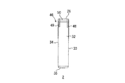
図2は、インクカートリッジ2がヘッドホルダ5に装着されている状態を示す断面図、図3は、インクカートリッジ2(ブラック以外のインクカートリッジ)の背面図、図4は、ヘッドホルダ5の平面図である。次に、これら図2ないし図4を参照して、インクカートリッジ2、インクジェットヘッド4およびヘッドホルダ5について詳述する。
2 is a cross-sectional view showing a state where the
インクカートリッジ2は、図1に示すように、シアン、マゼンタ、イエロー、ブラックの各色ごとに設けられており、シアン、マゼンタ、イエローのインクがそれぞれ充填されている各インクカートリッジ2C、2Mおよび2Yに対して、使用頻度がより多いブラックのインクが充填されているインクカートリッジ2Kが、やや幅広に形成されており、これらがキャリッジ6の移動方向に沿って順次ヘッドホルダ5に装着されている。
As shown in FIG. 1, the
各インクカートリッジ2は、図2に示すように、上部が開放され底部が閉鎖される矩形筒状のケース部材25と、そのケース部材25の上面を覆う上蓋部材26とを備えており、ケース部材25内には、インクを吸収した多孔質材27を収容する多孔質材室28と、インクを収容するインク室29と、多孔質材室28と大気とを連通させる大気連通室30とが区画形成されている。
As shown in FIG. 2, each
ケース部材25は、前壁31、後壁32、両側壁33および34(図3参照)および底壁35が一体として形成されるとともに、その内側には、前壁31および後壁32からそれぞれ内側に所定の間隔を隔てて対向配置され、ケース部材25の前後方向を仕切るように両側壁33および34の間に架設される前側仕切り壁36および後側仕切り壁37と、底壁35の内側に所定の間隔を隔てて対向配置され、前側仕切り壁36および後側仕切り壁37の下端部の間を閉鎖するように両側壁33および34の間に架設される底側仕切り壁38とが設けられる2重壁構造として形成されている。また、底壁35と底側仕切り壁38との間であっってケース部材25の前後方向略中央部には、それらの間に形成される空間を前後方向に仕切るように分割仕切り壁39が設けられている。
In the
そして、多孔質材室28は、両側壁33および34の間であって、前側仕切り壁36、後側仕切り壁37および底側仕切り壁38によって区画される内側の空間として形成されており、その多孔質材室28内に、ウレタンフォームなどからなる多孔質材27が、インクを吸収した状態で収容されている。
The
また、インク室29は、両側壁33および34の間であって、前壁31および前側仕切り壁36によって区画される鉛直方向の空間と、その空間に連続し、底壁35、底側仕切り壁38および分割仕切り壁39によって区画される水平方向前方側の空間とによって、断面略L字状の空間として形成されている。
The
また、大気連通室30は、両側壁33および34の間であって、後壁32および後側仕切り壁37によって区画される鉛直方向の空間と、その空間に連続し、底壁35、底側仕切り壁38および分割仕切り壁39によって区画される水平方向後方側の空間とによって、断面略L字状の空間として形成されている。
The
そして、インク室29において、底側仕切り壁38における分割仕切り壁39の前方側近傍には、多孔質材室28とインク室29とを連通させるための連通孔40が貫通形成されるとともに、底壁35における前方側端部(インクカートリッジ2の底部における前方側端部)には、インク室29からインクジェットヘッド4にインクを供給するための第1係止部としてのインク供給口41が貫通形成されている。
In the
このインク供給口41は、インクカートリッジ2の重心よりも前方側に位置し、次に述べるシール部材57に係止可能なリング状の前側凹部42が、底壁35の底面から上向きに凹設されるとともに、その上面には、フィルタ43が設けられている。
The
また、大気連通室30において、底壁35には、大気に開放される大気開放口44が貫通形成されるとともに、上端部には、多孔質材室28と大気連通室30とを連通させるための断面略逆U字状の空気連通路45が形成されている。
Further, in the
そして、このケース部材25には、後壁32における上端部(インクカートリッジ2の上部における後方側端部)に、第2係止部としての係止部材46が形成されるとともに、底壁35における後方側端部(インクカートリッジ2の底部における後方側端部)に、後側凹部47が形成されている。
The
係止部材46は、インクカートリッジ2の重心よりも後方側に位置し、図3にも示すように、後壁32の幅方向両側から、斜め上方に向かって幅広に突出する略三角形状の1対の係止側板48および49と、それら係止側板48および49の上端部の間を覆う係止上側板50とが一体に形成される背面視が下に開放する略コ字状をなし、互いに対向する1対の係止側板48および49が、後述するヘッドホルダ5の各係止溝部72(図4参照)に嵌め込み可能であって、かつ、それらの間で、後述するヘッドホルダ5の係止突起71(図4参照)を受け入れ可能に形成されている。
The locking
なお、図3には、シアン、マゼンタ、イエローの各インクカートリッジ2C、2Mおよび2Yが示されており、ブラックのインクカートリッジ2Kは、これら各インクカートリッジ2C、2Mおよび2Yよりも幅広に形成されている。
FIG. 3 shows cyan, magenta, and
また、後側凹部47は、インクカートリッジ2の重心よりも後方側に位置し、底壁35の底面から、前後方向に沿う底面視矩形状であって、側断面視略半円状となるように、上向きに凹設されている。
The rear
また、上蓋部材26は、略矩形板状をなし、ケース部材25の上面を覆うように取り付けられており、その上面の前方側端部には、後述するレバー部材73の嵌合溝75に嵌合される嵌合突起51が上向きに突出形成されるとともに、その上面の中央部にも、後述するレバー部材73の押圧突起76を受け入れる受入溝52が形成されている。
Further, the
また、インクヘットヘッド4は、各インクカートリッジ2に対応してそれぞれ設けられており、図2に示すように、ヘッドホルダ5の下部に支持されている。
Further, the
各インクジェットヘッド4は、インクをノズルから液滴として噴射させるための複数の噴射チャンネル(図示せず)を備えるアクチュエータ53と、このアクチュエータ53の上面に接合され、アクチュエータ53の各噴射チャンネルにインクを供給するためのマニホールド54とを備えている。
Each
マニホールド54は、インクカートリッジ2からインクを導入するための筒状のインク導入部55と、アクチュエータ53の各噴射チャンネルにインクを分配供給するためのインク供給部56とが一体形成されている。
The manifold 54 is integrally formed with a cylindrical
インク導入部55の、後述する支持板65の開口部67内に侵入した上端部には、弾性材料からなる筒状のシール部材57が嵌合固定されており、インクカートリッジ2の底壁35に形成された前側凹部42が、このシール部材57の上端部に弾接的に嵌め込まれることにより、インク室29のインク供給口41がそのシール部材57を介してインク導入部55に接続される。
A
そして、インクカートリッジ2の多孔質材27に吸収されているインクは、その多孔質材室28から連通孔40を介してインク室29に供給され、そのインク室29に供給されたインクは、インク供給口41から、インク導入部55を介してインク供給部56に供給され、さらに、そのインク供給部29から、アクチュエータ53の各噴射チャンネル内に分配供給される。アクチュエータ53は、圧電セラミック材料などからなり、アクチュエータ53の各噴射チャンネル内に供給されたインクは、アクチュエータ53の変形により、その容積減少時に、ノズルから液滴として噴射され、一方、容積増大時には、インク供給部56から再び噴射チャンネル内にインクが導入される。このような動作が繰り返されることにより、用紙などに所定の印字が形成される。
The ink absorbed in the
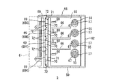
ヘッドホルダ5は、図2および図4に示すように、幅方向(キャリッジ6の移動方向)両側に対向配置される1対の側板58および59と、その1対の側板58および59の後端部の間を連結する後板60と、1対の側板58および59の下端部と、後板60の下端部との間を覆う底板61と、その底板61の前端部から斜め前側上方に向かって延びる前受板62とを備える、前方側が開放される断面略L字状をなし、その後方側においてキャリッジ6に一体的に搭載されている。
As shown in FIGS. 2 and 4, the
底板61には、各インクジェットヘッド4を下方に向かって突出させるための開口部63が形成されるとともに、その幅方向に沿って前後方向に互いに所定の間隔を隔てて対向する係止段部64が形成されており、その係止段部64には、各インクカートリッジ2を支持するための支持板65が着脱自在に係止されている。
The
支持板65には、図4に示すように、仕切板66と、その前方側端部に、各インクカートリッジ2のインク供給口41と対向する開口部67と、その後方側端部に、各インクカートリッジ2の後側凹部47と対向する後側凸部68とが、各インクカートリッジ2に対応してそれぞれ形成されている。
As shown in FIG. 4, the
すなわち、各仕切板66は、支持板65の幅方向において、各インクカートリッジ2の幅に対応する所定の間隔を隔てて、各インクカートリッジ2を仕切るように、前後方向に沿ってそれぞれ(3つ)形成されている。
In other words, each
この仕切板66によって、各インクカートリッジ2が、一方の側板58と仕切板66、各仕切板66の間、および、他方の側板59と仕切板66との間に、それぞれ装着され、図1に示すように、4つのインクカートリッジ2がヘッドホルダ5の幅方向(キャリッジ6の移動方向)に沿って並列状態で装着される。
With this
また、各開口部67は、各インクカートリッジ2に対応して、一方の側板58と仕切板66、各仕切板66の間、および、他方の側板59と仕切板66との間における支持板65の前方側端部にそれぞれ(4つ)開口形成されており、各開口部67内には、シール部材57が上向きに突出するような状態で接着固定されている。
In addition, each opening 67 corresponds to each
また、各後側凸部68は、各インクカートリッジ2に対応して、一方の側板58と仕切板66、各仕切板66の間、および、他方の側板59と仕切板66との間における支持板65の後方側端部において、それぞれ(4つ)突出形成されている。各後側凸部68は、各後側凹部47に係止可能なように、支持板65の上面から、前後方向に沿う平面視矩形状であって、側断面視略半円状となるように、上向きに凸設されている。
Further, each
また、後板60は、その上端部が後方側に傾斜するように形成されており、その上端部に、各インクカートリッジ2の係止部材46と対向する係止部69が、一方の側板58と仕切板66、各仕切板66の間、および、他方の側板59と仕切板66との間にそれぞれ形成されている。
Further, the
各係止部69は、各インクカートリッジ2の係止部材46を誘い込む誘込部としての誘込溝70と、その誘込溝70内に形成される係止突起71とを備えている。
Each locking
誘込溝70は、各インクカートリッジ2の幅とほぼ同じ幅(すなわち、ブラックのインクカートリッジ2Kが装着される係止部69Kでは幅広となる。)で、前方側に開放される平面視略U字状をなし、その両端部が、各インクカートリッジ2の係止側板48および49を良好に誘い込むために、前方側に向かって幅広に形成されている。
The
また、係止突起71は、各誘込溝70内の幅方向略中央部において、幅方向に延びる平面視略矩形状をなし、誘込溝70の両端部と所定の間隔が隔てられるような状態で、上向きに突出形成されており、誘込溝70の両端部とその係止突起71との間が、各係止側板48および49を係止可能とする係止溝部72とされている。
Further, the locking
また、キャリッジ6の上端部には、各インクカートリッジ2の上蓋部材26に対向可能なレバー部材73が上下方向に揺動可能に支持されている。このレバー部材73は、その後方側端部が、キャリッジ6に支持される揺動軸74に挿通支持されることによって、揺動軸74の周りに回動可能かつ上下移動可能に設けられており、その前方側の下面には、上蓋部材26の嵌合突起51を受け入れる嵌合溝75が形成されるとともに、その下面の中央部にも、上蓋部材26の受入溝52に挿入される押圧突起76が形成されている。また、嵌合溝75と押圧突起76との間には、上蓋部材26の上面に弾接される弾性当接部材78が設けられるとともに、レバー部材73の後方側上面には、キャリッジ6の上端部の壁6aに係止可能な係止爪部77が上向きに突出形成されている。
A
そして、このレバー部材73は、揺動軸74の周りに設けられる図示しないばねの付勢力によって、常には、仮想線で示す開放状態とされ、かつ揺動軸74に対し上下に移動する状態とされている。インクカートリッジ2の装着時には、レバー部材73の前方側端部を、ばねの付勢力に抗して下側に向けて回動させて、上蓋部材26の上面に弾性当接部材78を弾接させるとともに、上蓋部材26の嵌合突起51を嵌合溝75によって受け入れ、かつ、押圧突起76を上蓋部材26の受入溝52に挿入すると、その状態で、係止爪部77がばねの付勢力で上昇してキャリッジ6の壁6aの前端部に係止される。そのため、インクカートリッジ2は、このレバー部材73によって下方に押圧された状態で、ヘッドホルダ5に固定される。また、レバー部材73を押し下げて係止爪部77を壁6aから解除すると、レバー部材73が開放される。
The
次に、各インクカートリッジ2のヘッドホルダ5に対する装着について説明する。
Next, attachment of each
インクカートリッジ2をヘッドホルダ5に装着するには、まず、図5に示すように、インクカートリッジ2の底壁35の前方側端部に形成されるインク供給口41の前側凹部42を、支持板65の開口部67から突出するシール部材57に嵌め込むようにする。そうすると、前側凹部42はインクカートリッジ2の重心よりも前方にあるので、インクカートリッジ2は、その前側凹部42を支点として、重心方向に確実に回動され、つまり、自重によって後方に傾倒して、インクカートリッジ2の重心よりも後方側にある係止部材46の各係止側板48および49が、誘込溝70によって良好に案内される。その際、図6に示すように、係止側板48および49の上端部の外側の面は、インクカートリッジ2の側壁33および34の外側の面と同じとされ、かつ誘込溝70の両側の円弧状テーパ面とほぼ対応したテーパ面を有している。さらに、係止突起71の上端は、誘込溝70の上端部よりも少し低く位置している。このため、係止側板48および49の間に係止突起71が入り込むよりも先に、係止側板48および49のテーパ面が誘込溝70のテーパ面と対応し、インクカートリッジ2の中心位置が幅方向に多少ずれていても、誘込溝70の中心とほぼ一致するように、インクカートリッジ2が案内され、係止部69の各係止溝部72に係止される(つまり、係止部69の係止突起71が各係止側板48および49の間に嵌め込まれる)。また、これとともに、同じく、インクカートリッジ2の重心よりも後方側にある後側凹部47が、支持板65の後側凸部68に係止される。
In order to attach the
そのため、前側凹部42をシール部材57に嵌め込むのみの操作により、インクカートリッジ2を、簡単かつ確実にヘッドホルダ5に対して装着することができる。
Therefore, the
そして、その後、上記したように、レバー部材73を下側に向けて回動させて、上蓋部材26に当接させることにより、インクカートリッジ2をヘッドホルダ5に固定させればよい。
Then, as described above, the
そして、このようにして装着されたインクカートリッジ2は、レバー部材73による固定のみではなく、インクカートリッジ2における底壁35の前方側端部における前側凹部42とヘッドホルダ5のシール部材57との嵌合、および、後壁32の上方側端部における係止部材46とヘッドホルダ5の係止部69との係止によって、対角線状で係止され、さらには、インクカートリッジ2における底壁35の後方側端部における後側凹部42とヘッドホルダ5の後側凸部68との係止によって、インクカートリッジ2における底壁35の前方側端部、後壁32の上端部および底壁35の後方側端部の3箇所において係止され、位置固定されるので、たとえ、そのヘッドホルダ5がキャリッジ6の移動により高速で左右方向に移動しても、インクカートリッジ2が左右に振れることを、有効に防止することができる。その結果、印字時においてインクに偏りが生じることを低減することができ、良好なインクの使い切りを確保することができる。
The
また、このようなインクカートリッジ2では、インクカートリッジ2における底壁35の前方側端部における前側凹部42とヘッドホルダ5のシール部材57との嵌合によって、インクカートリッジ2をヘッドホルダ5に係止させることができると同時に、インクカートリッジ2とインクジェットヘッド4とのインク流路の接続ができるので、別途、インク供給口41をヘッドホルダ5に装着させる操作を必要とすることなく、そのまま、インクカートリッジ2からインクジェットヘッド4にインクを供給可能な状態とすることができる。そのため、より一層簡易な構成として、かつ、簡易な操作により、インクカートリッジ2の装着を達成することができる。
In such an
また、このようなインクカートリッジ2のヘッドホルダ5への装着時には、係止部材46の各係止側板48および49が、誘込溝70によって良好に案内されて、係止部69の各係止溝部72に係止されるので、より一層、簡単かつ確実になインクカートリッジ2のヘッドホルダ5に対する装着が達成されている。
When the
そのため、このようなインクカートリッジ2およびヘッドホルダ5を備えるカラーインクジェットプリンタ1では、インクカートリッジ2が確実にヘッドホルダ5に対して装着されているので、インクの使い切りが良好で、かつ、良好な印字を達成することができる。
For this reason, in the color inkjet printer 1 including the
なお、係止部69と係止部材46とを係止方向に案内するためのテーパ面は、誘込溝70または係止側板48および49の一方向にのみあればよく、また、係止側板48および49の内面と係止突起71との間にあってもよい。さらに、係止突起71を省略して誘込溝70と係止側板48および49とで、インクカートリッジ2の左右方向の位置決めを行なってもよい。
It should be noted that the tapered surface for guiding the locking
1 カラーインクジェットプリンタ
2 インクカートリッジ
4 インクジェットヘッド
5 ヘッドホルダ
32 後壁
35 底壁
41 インク供給口
42 前側凹部
46 係止部材
47 後側凹部
70 誘込溝
DESCRIPTION OF SYMBOLS 1
Claims (1)
1対の側板と、A pair of side plates;
前記1対の側板の後端部の間を連結し、上端部に係止部が形成された後板と、Connecting between the rear end portions of the pair of side plates, and a rear plate having a locking portion formed at the upper end portion;
前記1対の側板の下端部と前記後板の下端部との間を覆う底板と、A bottom plate covering a space between a lower end portion of the pair of side plates and a lower end portion of the rear plate;
開口部を有し、前記底板に支持される支持板と、A support plate having an opening and supported by the bottom plate;
前記後板の上方に位置する後方側端部を中心に揺動可能であり、前方側の下面に嵌合溝が形成されたレバー部材と、A lever member that is swingable around a rear side end located above the rear plate, and in which a fitting groove is formed on the lower surface of the front side;
を備え、 With
前記インクカートリッジは、 The ink cartridge is
その底部における前方側端部に形成され、インクカートリッジが装着されたときに前記支持板の前記開口部に係止し、前記インクジェットヘッドにインクを供給するためのインク供給口を兼ねる第1のカートリッジ側係止部と、A first cartridge that is formed at the front end portion of the bottom portion and serves as an ink supply port for engaging with the opening of the support plate and supplying ink to the inkjet head when the ink cartridge is mounted. Side locking part,
その上部における後方側端部において前記第1のカートリッジ側係止部と対角線状の位置に形成され、前記インクカートリッジが装着されたときに前記係止部に係止する第2のカートリッジ側係止部と、A second cartridge side latch that is formed at a position diagonal to the first cartridge side latching portion at the rear end portion at the upper portion and latches to the latching portion when the ink cartridge is mounted. And
前記上部における前方側端部に形成され、前記嵌合溝に嵌合される嵌合突起と、を備えるとともに、A fitting projection formed on the front side end portion in the upper part and fitted in the fitting groove;
前記第1のカートリッジ側係止部は、前記インクカートリッジの重心よりも前方側に設けられ、前記第2のカートリッジ側係止部は、前記インクカートリッジの重心よりも後方側に設けられており、The first cartridge side locking portion is provided on the front side of the center of gravity of the ink cartridge, and the second cartridge side locking portion is provided on the rear side of the center of gravity of the ink cartridge,
前記インクカートリッジの上端側を前方に傾けた姿勢で、前記第1のカートリッジ側係止部を前記開口部に係止させ、前記第1のカートリッジ側係止部を支点として後方に傾倒するように回動させて、前記第2のカートリッジ側係止部を前記係止部に係止させることにより、前記インクカートリッジが装着され、この装着されたインクカートリッジは、前記レバー部材が下側に向けて回動されて前記嵌合溝が前記嵌合突起に嵌合することで固定されることを特徴とする、インクジェット記録装置。With the posture in which the upper end side of the ink cartridge is tilted forward, the first cartridge side locking portion is locked to the opening, and tilted backward with the first cartridge side locking portion as a fulcrum. The ink cartridge is mounted by rotating and locking the second cartridge side locking portion to the locking portion. The mounted ink cartridge has the lever member facing downward. An ink jet recording apparatus, wherein the ink jet recording apparatus is fixed by being rotated and the fitting groove is fitted into the fitting protrusion.
Priority Applications (1)
| Application Number | Priority Date | Filing Date | Title |
|---|---|---|---|
| JP2005325779A JP4487904B2 (en) | 2005-11-10 | 2005-11-10 | Inkjet recording device |
Applications Claiming Priority (1)
| Application Number | Priority Date | Filing Date | Title |
|---|---|---|---|
| JP2005325779A JP4487904B2 (en) | 2005-11-10 | 2005-11-10 | Inkjet recording device |
Related Parent Applications (1)
| Application Number | Title | Priority Date | Filing Date |
|---|---|---|---|
| JP2001214331A Division JP3783585B2 (en) | 2001-03-30 | 2001-07-13 | Ink cartridge and ink jet recording apparatus |
Publications (3)
| Publication Number | Publication Date |
|---|---|
| JP2006056272A JP2006056272A (en) | 2006-03-02 |
| JP2006056272A5 JP2006056272A5 (en) | 2008-09-04 |
| JP4487904B2 true JP4487904B2 (en) | 2010-06-23 |
Family
ID=36104127
Family Applications (1)
| Application Number | Title | Priority Date | Filing Date |
|---|---|---|---|
| JP2005325779A Expired - Fee Related JP4487904B2 (en) | 2005-11-10 | 2005-11-10 | Inkjet recording device |
Country Status (1)
| Country | Link |
|---|---|
| JP (1) | JP4487904B2 (en) |
-
2005
- 2005-11-10 JP JP2005325779A patent/JP4487904B2/en not_active Expired - Fee Related
Also Published As
| Publication number | Publication date |
|---|---|
| JP2006056272A (en) | 2006-03-02 |
Similar Documents
| Publication | Publication Date | Title |
|---|---|---|
| JP4026407B2 (en) | Ink cartridge and ink jet recording apparatus using the same | |
| JP4561395B2 (en) | Attachment and liquid supply device | |
| JP4051916B2 (en) | Inkjet recording device | |
| EP1790478B1 (en) | Liquid ejecting apparatus | |
| JP3800807B2 (en) | Inkjet recording device | |
| US6896352B2 (en) | Ink jet recording apparatus | |
| JP2006231851A (en) | Ink jet recorder | |
| JP3873675B2 (en) | ink cartridge | |
| JP3783585B2 (en) | Ink cartridge and ink jet recording apparatus | |
| US9937724B2 (en) | Liquid ejecting apparatus | |
| JP6714857B2 (en) | Waste liquid container and liquid ejecting apparatus | |
| JP4973764B2 (en) | Liquid supply device | |
| US10434781B2 (en) | Inkjet printing apparatus | |
| JP4487904B2 (en) | Inkjet recording device | |
| JPH09239995A (en) | Capping device for ink jet recording head | |
| US6099114A (en) | Ink cartridge and ink jet printer | |
| JP2006056272A5 (en) | ||
| JP4760401B2 (en) | Cap and liquid ejecting apparatus | |
| JP3901202B2 (en) | Inkjet recording device | |
| JP7136310B2 (en) | liquid consumption device | |
| US6209982B1 (en) | Ink jet recording device capable of reliably discharging air bubble during purging operations | |
| JP7201110B2 (en) | Inkjet recording device | |
| JP2019025821A (en) | Liquid consuming device | |
| JP4161538B2 (en) | Inkjet recording apparatus and its emergency cartridge | |
| JP7024241B2 (en) | Inkjet recording device |
Legal Events
| Date | Code | Title | Description |
|---|---|---|---|
| A621 | Written request for application examination |
Free format text: JAPANESE INTERMEDIATE CODE: A621 Effective date: 20080714 |
|
| A521 | Written amendment |
Free format text: JAPANESE INTERMEDIATE CODE: A523 Effective date: 20080722 |
|
| TRDD | Decision of grant or rejection written | ||
| A01 | Written decision to grant a patent or to grant a registration (utility model) |
Free format text: JAPANESE INTERMEDIATE CODE: A01 Effective date: 20100309 |
|
| A01 | Written decision to grant a patent or to grant a registration (utility model) |
Free format text: JAPANESE INTERMEDIATE CODE: A01 |
|
| A61 | First payment of annual fees (during grant procedure) |
Free format text: JAPANESE INTERMEDIATE CODE: A61 Effective date: 20100322 |
|
| FPAY | Renewal fee payment (event date is renewal date of database) |
Free format text: PAYMENT UNTIL: 20130409 Year of fee payment: 3 |
|
| R150 | Certificate of patent or registration of utility model |
Ref document number: 4487904 Country of ref document: JP Free format text: JAPANESE INTERMEDIATE CODE: R150 Free format text: JAPANESE INTERMEDIATE CODE: R150 |
|
| FPAY | Renewal fee payment (event date is renewal date of database) |
Free format text: PAYMENT UNTIL: 20130409 Year of fee payment: 3 |
|
| FPAY | Renewal fee payment (event date is renewal date of database) |
Free format text: PAYMENT UNTIL: 20140409 Year of fee payment: 4 |
|
| LAPS | Cancellation because of no payment of annual fees |