JP4484290B2 - Apparatus and method for directly connecting a terminal station to an ATM - Google Patents
Apparatus and method for directly connecting a terminal station to an ATM Download PDFInfo
- Publication number
- JP4484290B2 JP4484290B2 JP36012099A JP36012099A JP4484290B2 JP 4484290 B2 JP4484290 B2 JP 4484290B2 JP 36012099 A JP36012099 A JP 36012099A JP 36012099 A JP36012099 A JP 36012099A JP 4484290 B2 JP4484290 B2 JP 4484290B2
- Authority
- JP
- Japan
- Prior art keywords
- interface
- tdm
- packet
- switch
- trunk
- Prior art date
- Legal status (The legal status is an assumption and is not a legal conclusion. Google has not performed a legal analysis and makes no representation as to the accuracy of the status listed.)
- Expired - Lifetime
Links
Images

Classifications
-
- H—ELECTRICITY
- H04—ELECTRIC COMMUNICATION TECHNIQUE
- H04Q—SELECTING
- H04Q11/00—Selecting arrangements for multiplex systems
- H04Q11/04—Selecting arrangements for multiplex systems for time-division multiplexing
- H04Q11/0428—Integrated services digital network, i.e. systems for transmission of different types of digitised signals, e.g. speech, data, telecentral, television signals
- H04Q11/0478—Provisions for broadband connections
-
- H—ELECTRICITY
- H04—ELECTRIC COMMUNICATION TECHNIQUE
- H04Q—SELECTING
- H04Q3/00—Selecting arrangements
- H04Q3/0016—Arrangements providing connection between exchanges
-
- H—ELECTRICITY
- H04—ELECTRIC COMMUNICATION TECHNIQUE
- H04L—TRANSMISSION OF DIGITAL INFORMATION, e.g. TELEGRAPHIC COMMUNICATION
- H04L12/00—Data switching networks
- H04L12/54—Store-and-forward switching systems
- H04L12/56—Packet switching systems
- H04L12/5601—Transfer mode dependent, e.g. ATM
- H04L2012/5614—User Network Interface
- H04L2012/5618—Bridges, gateways [GW] or interworking units [IWU]
-
- H—ELECTRICITY
- H04—ELECTRIC COMMUNICATION TECHNIQUE
- H04L—TRANSMISSION OF DIGITAL INFORMATION, e.g. TELEGRAPHIC COMMUNICATION
- H04L12/00—Data switching networks
- H04L12/54—Store-and-forward switching systems
- H04L12/56—Packet switching systems
- H04L12/5601—Transfer mode dependent, e.g. ATM
- H04L2012/5629—Admission control
- H04L2012/563—Signalling, e.g. protocols, reference model
-
- H—ELECTRICITY
- H04—ELECTRIC COMMUNICATION TECHNIQUE
- H04L—TRANSMISSION OF DIGITAL INFORMATION, e.g. TELEGRAPHIC COMMUNICATION
- H04L12/00—Data switching networks
- H04L12/54—Store-and-forward switching systems
- H04L12/56—Packet switching systems
- H04L12/5601—Transfer mode dependent, e.g. ATM
- H04L2012/5638—Services, e.g. multimedia, GOS, QOS
- H04L2012/5663—Support of N-ISDN
-
- H—ELECTRICITY
- H04—ELECTRIC COMMUNICATION TECHNIQUE
- H04Q—SELECTING
- H04Q2213/00—Indexing scheme relating to selecting arrangements in general and for multiplex systems
- H04Q2213/1309—Apparatus individually associated with a subscriber line, line circuits
-
- H—ELECTRICITY
- H04—ELECTRIC COMMUNICATION TECHNIQUE
- H04Q—SELECTING
- H04Q2213/00—Indexing scheme relating to selecting arrangements in general and for multiplex systems
- H04Q2213/13176—Common channel signaling, CCS7
-
- H—ELECTRICITY
- H04—ELECTRIC COMMUNICATION TECHNIQUE
- H04Q—SELECTING
- H04Q2213/00—Indexing scheme relating to selecting arrangements in general and for multiplex systems
- H04Q2213/13179—Fax, still picture
-
- H—ELECTRICITY
- H04—ELECTRIC COMMUNICATION TECHNIQUE
- H04Q—SELECTING
- H04Q2213/00—Indexing scheme relating to selecting arrangements in general and for multiplex systems
- H04Q2213/13196—Connection circuit/link/trunk/junction, bridge, router, gateway
-
- H—ELECTRICITY
- H04—ELECTRIC COMMUNICATION TECHNIQUE
- H04Q—SELECTING
- H04Q2213/00—Indexing scheme relating to selecting arrangements in general and for multiplex systems
- H04Q2213/13199—Modem, modulation
-
- H—ELECTRICITY
- H04—ELECTRIC COMMUNICATION TECHNIQUE
- H04Q—SELECTING
- H04Q2213/00—Indexing scheme relating to selecting arrangements in general and for multiplex systems
- H04Q2213/13204—Protocols
-
- H—ELECTRICITY
- H04—ELECTRIC COMMUNICATION TECHNIQUE
- H04Q—SELECTING
- H04Q2213/00—Indexing scheme relating to selecting arrangements in general and for multiplex systems
- H04Q2213/1329—Asynchronous transfer mode, ATM
-
- H—ELECTRICITY
- H04—ELECTRIC COMMUNICATION TECHNIQUE
- H04Q—SELECTING
- H04Q2213/00—Indexing scheme relating to selecting arrangements in general and for multiplex systems
- H04Q2213/13292—Time division multiplexing, TDM
-
- H—ELECTRICITY
- H04—ELECTRIC COMMUNICATION TECHNIQUE
- H04Q—SELECTING
- H04Q2213/00—Indexing scheme relating to selecting arrangements in general and for multiplex systems
- H04Q2213/1338—Inter-exchange connection
-
- H—ELECTRICITY
- H04—ELECTRIC COMMUNICATION TECHNIQUE
- H04Q—SELECTING
- H04Q2213/00—Indexing scheme relating to selecting arrangements in general and for multiplex systems
- H04Q2213/13399—Virtual channel/circuits
Description
【0001】
【発明の属する技術分野】
本発明は電気通信の分野、とりわけ、交換電話網における時分割多重 (TDM)交換機を非同期転送モード (ATM)設備に直接トランク接続するための装置と方法に関するものである。
【0002】
【従来の技術】
ATM交換設備は、電気通信業者によってデータ転送用として一般的に使用されているが、公衆電話網 (PSTN)における交換機間の電話呼に関するベアラー・トラフィックを運ぶのにより頻繁に使用される。 PSTNにおいてATM設備への接続を可能にすることは、 ATM設備提供業者が顧客層を拡げることを可能にし、結果として、ATM網インフラストラクチャへの投資収益を改善するものである。ATM設備では呼のルーティングが非常に柔軟である、と云うのは、ATMによるルーティングは、現今のPSTNにおける呼ルーティングを支配するハイアラーキー構造による制約を受けないからである。その上、ATM設備は従来のTDM設備よりも比較的低いコストで所有し、運用できる。また、ATM交換機はTDM交換装置よりも所要設置面積が小さいので機械設備の維持費も少なくてすむ。
【0003】
PSTN交換機が交換機間での呼を実現するようにATM幹線網を使用できるようにする1つの方法が、米国特許出願 第09/158,855号(1998年9月23日)“TRNSIT TRUNK SUBNETWORK SYSTEM(中継回線サブネットワーク・システム)”に記述されており、その開示内容をここで参照して取り込む。その中継回線サブネットワークは、マルチサービス・プラットフォーム (MSP;Multi-Service Platform)と称するTDM交換装置とATMバックボーン・ネットワークの間のインターフェースを含む。MSPはパルス符号変調 (PCM)データをATMセルへ、また、その逆の変換を行う。MSPはまた、TDMトランクをATMの仮想チャンネル・コネクション (VCC;Virtual Channel Connection )にマップすることによって、中継回線サブネットワークにおけるTDM交換装置間のベアラー・トラフィックの転送をATMバックボーン・ネットワークを通して行うことを可能にする。
【0004】
中継回線サブネットワークはPSTNにおける輻輳対策として形成されてきた、と云うのは、中継回線サブネットワークにおいてはTDM交換装置間の通信ルート設定がATMバックボーン・ネットワークを通して行えるからである。中継回線サブネットワークは又、ベアラー・トラフィックの効率的使用を保証するために、応答的予測的にVCCの割付をコントロールすることで動的な帯域幅管理を可能とする。 従って、 ATMバックボーン・ネットワークの設備は要求に比例した分だけしか予約されず、他のネットワークからのデータ転送などのような他の機能がネットワークの余剰能力を使えるようになる。
【0005】
ATM設備提供業者は又、競合する地域交換通信事業者 (CLEC;Competitive Local Exchange Carrier )によるATM設備へのアクセスの需要を経験している。 ATM設備が呼に伴うベアラー・トラフィックの転送を低コストで提供するため、CLECはATM設備を彼らの運用コストを下げてより競争力のあるサービス提供を可能にする有効な代案であると見ている。 米国で最近施行された遠隔通信規則によれば、CLECがその顧客に対して地域サービスを提供するために、既存の地域交換通信事業者 (ILEC;Incumbent Local Exchange Carriers )は、ILECが所有し、かつ運用している設備のリースによるアクセスを許可しなければならない。 そのように強制された取り決めのもとでは、CLECはILECの設備にアクセスする度に料金を賦課される。 この料金は結果としてCLECの運営純益を低下させる。 そのため、 ATMバックボーン・ネットワークにPSTN交換機を最も簡単かつ低費用で統合できるように造られた機器に関心がもたれる。
【0006】
従って、 ATMバックボーン・ネットワークにPSTN交換機を接続するために必要な部品の数が少なくて済み、それによって資本投下が少なくなるような装置が必要である。また、TDM交換装置の機械設備にATMインターフェースを組み込むための装置は、そのシステムの所要設置面積を低減させるものであることも要求される。そのような設備の統合は基本的に所要設置面積を減らし、結果的に運営経費を減らす。
【0007】
【発明が解決しようとする課題】
本発明の目的の1つは、TDMをATMに直接接続する装置であって、TDM交換装置とATM設備との間の接続を簡単にし、 ATMバックボーン・ネットワークへの接続を行うために必要な部品の数を減らすような装置を提供することである。
【0008】
本発明のさらなる目的は、TDM交換装置とATMバックボーン・ネットワークとのインターフェース装置であって、同じ目的で使われている従来のインターフェース装置よりも所要設置面積の小さな装置を提供することである。
【0009】
本発明のさらなる目的は、TDM交換装置とATMバックボーン・ネットワークの間のインターフェース装置であって、TDM交換装置のトランク周辺装置をエミュレートすることによりTDM交換装置のスイッチファブリック・インターフェースに直接接続可能な装置を提供することである。
【0010】
本発明のさらなる目的は、TDM交換装置とATMバックボーン・ネットワークの間のインターフェース装置であって、TDM交換装置の計算モジュール或いはメッセージ伝達システムに修正を加えることなく、その計算モジュールと対話ができる装置を提供することである。
【0011】
【課題を解決するための手段】
本発明は上記課題に従い、TDM交換装置とATMバックボーン・ネットワークを直接トランク接続するために次のもので構成される装置を提供するものである。 すなわち、ATMセルをバックボーン・ネットワークへ転送し、また、ATMバックボーン・ネットワークからATMセルを受信するために1つのATMリンクへの接続ができるように作られたインターフェース、並びに、PCMデータをTDM交換装置のスイッチ本体部へ転送し、また、 TDM交換装置のスイッチ本体部からPCMデータを受信するために少なくとも1つのシリアル・リンクへ接続ができるように作られたインターフェースとして構成された装置を提供するものである。上記インターフェースはTDM交換装置のトランク周辺装置をエミュレートするようにも作られているので、 TDM交換装置の計算モジュールは、計算モジュール固有のトランク周辺装置と交信するためのプロトコルを使って上記インターフェースと交信ができる。
【0012】
従って、本発明はTDM交換装置とATM設備間に、従来の技術によるインターフェースに代って簡単なインターフェース装置を提供するものである。 本発明はさらに、そのインターフェースをTDM交換装置インフラストラクチャに統合可能なものにする。このことは比較的少ない部品による簡単なインターフェースを実現し、より少ない資金でATM設備への乗り換えを可能にする。
【0013】
本発明は又、次のようにTDM交換装置とATMバックボーン・ネットワークを直接トランク接続する方法を提供する。この方法は、PCMデータをATMセルへ、及びその逆の変換ができるようなインターフェースを形成するステップを含み、インターフェースがその交換機固有のメッセージ・プロトコルを使ってその交換機の計算モジュールと交信することを可能にしている。 それによって、インターフェースはTDM交換装置のトランク周辺装置をエミュレートする。 インターフェースはTDM交換装置のスイッチファブリック・インターフェースのシリアル・リンクに直接接続されることによって、TDM交換装置とATMバックボーン・ネットワークを直接トランク接続することを可能にする。
【0014】
従って、本発明はTDM交換装置とATMバックボーン・ネットワークの間の直接ATMトランク接続を提供する方法にも適する。直接ATMトランク接続をすると、 TDM交換装置とATMバックボーン・ネットワークを接続するのに必要な構成品の数が減る。これによって、PSTNからベアラー・トラフィックを取り込むためにATM設備を使うのに要する資金が少なくてすむ。また、インターフェースはより小さな空間しか占有しないので、 TDM交換装置の機械設備の中に組み込むことが可能である。
【0015】
【発明の実施の形態】
本発明は交換電話網におけるTDM交換装置とATM設備のインターフェースをとるための装置と方法に適したもので、TDMとATMの直接接続を可能にする。
【0016】
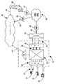
図1には、ATMバックボーン・ネットワーク45へのインターフェースを備えた従来の技術によるTDM交換装置10が示されており、公衆電話網(PSTN)で発生した呼を他のTDM交換装置(図示せず)に転送するためにATMバックボーン・ネットワークに載せかえることを可能とする。TDM交換装置 10はクラス5の端局(End-Office)である。 しかし、本発明はクラス5の端局に使うインターフェースに限られるものではなく、PSTNにおける如何なるクラスのTDM交換装置にも適用できることは理解されるべきである。 TDM交換装置 10は、当業者が明らかなように、ライン側、トランク側、及び、スイッチファブリック(switch fabric)15を含んでいる。
【0017】
TDM交換装置10のライン側はライン周辺装置(LP) 20を内蔵し、それらは加入者線21によって加入者構内の種々の機器に接続されている。 クラス5端局のライン周辺装置は、顧客構内に設置されている例えば、電話22、ファクシミリ24、モデム26、及びそれに類した機器をサポートする。
【0018】
TDM交換装置10のトランク側はスイッチファブリック・インターフェース 28を内蔵し、それらはパルス符号変調(PCM)データをスイッチファブリック15からトランク周辺装置 30へ、又はその逆の転送を行う。トランク周辺装置30は一般的にデジタル・トランク・コントローラ(DTC)と呼ばれている。 スイッチファブリック・インターフェース28はPCMデータの入出力を行うために、通常、高速光転送線(バス)を持っている。トランク周辺装置30は、スイッチファブリック・インターフェース28から受けるデータに対してはデマルチプレクサとして動作し、トランク32から受けるデータに対してはマルチプレクサとして動作する。 トランク周辺装置30は、スイッチファブリック・インターフェース28から光形式で受けるデータをトランク32を介して転送するための電気形式のデータに、又はその逆の変換を行う。 さらに、トランク周辺装置30は、TDM交換装置10の計算モジュール16とコントロール・メッセージを交換することによって呼データのスイッチファブリックからトランク32への経路設定、或いは、その逆の経路設定を可能にする。
【0019】
トランク32はマルチプレクサ34に接続され、マルチプレクサはトランク32の出力を多重化し、多重化された出力を光形式に変換する。光形式の出力は光リンク38を介してMSP 40に送られる。 光リンク38は通常OC-3の速さで動作する。MSP 40はPCMデータ形式の光信号を受け、PCMデータをATMセルに変換する。ATMセルは、要求に応じて設定されるか、或いは下記出願中の特許に記述されている様にキャッシュから選ばれてSVC(交換型仮想回線)を介して転送される。これは、米国特許出願 第09/165,189号(1998年10月02日)“METHOD AND APPARATUS FOR REDUCTION OF CALL SETUP RATE IN ATM NETWORK( ATMネットワークにおける呼設定率低減のための装置と方法)”に記述されており、その開示内容を参照して取り込む。
【0020】
TDM交換装置10、50及び呼マネージャ55は共通信号通信(CCS)ネットワーク60を通して信号メッセージを交換する。 CCSネットワーク60は通常、SS7(Signaling System 7)方式のネットワークであり、この分野では周知の方法で呼の設定及び呼の進行を制御するのに端局間でISUP(ISDN User Part)信号メッセージを交換するものである。
【0021】
図2は本発明の好適な実施例の概略図であり、 ATMインターフェースを物理的にTDM交換装置10の中に組み込めることを示している。 TDM交換装置10は呼に伴うベアラー・トラフィックを受け、ベアラー・トラフィックの少なくとも一部をATMバックボーン・ネットワークに接続する。この分野では周知の呼に伴うPCMデータはスイッチファブリック15を通して交換される。PCMデータはスイッチファブリック・インターフェース28A及び28Bを介してスイッチファブリック15から受け取られる。スイッチファブリック・インターフェースはMSP 40A及び40BのTDM物理インターフェースに直接接続される。 従って、従来はスイッチファブリック・インターフェース28A及び28BとMSP 40A及び40Bの間に存在したトランク周辺装置30(図1)及びマルチプレクサ34(図1)は消去されている。
【0022】
図2に示すインターフェース構成を実現するために、 MSP 40A及び40Bはトランク周辺装置30(図1)をエミュレートするように造られ、そのためTDM交換装置10の計算モジュール16は新しい構成のインターフェース部品に合わせる改修を必要としない。従って、MSPは、スイッチファブリック15を通して計算モジュール16から送られてくるコントロール・メッセージを受け、計算モジュール16で使われる固有のメッセージ通信用のプロトコルによってコントロール・メッセージに応答することを可能とする必要がある。また、MSPはトランク周辺装置30のその他の機能も実行できるように構成され、計算モジュール16からは各MSPがデジタル・トランク・コントローラのようなトランク周辺装置として見える必要がある。
【0023】
図1に示すように、計算モジュール16はトランク周辺装置30とコントロール・メッセージを授受する。これらのコントロール・メッセージはスイッチファブリックに入って来る、もしくは、出て行く呼を識別するのに用いられるとともに、出て行く呼に対してはトランク周辺装置30に繋がる適当なトランク・メンバー(Trunk members)へ経路を設定し、入って来る呼データに対してはスイッチファブリック15の適当な箇所に経路を設定する。 従って、MSP 40A及び40Bは同じコントロール・メッセージを計算モジュール16との間で授受する。 本発明によるインターフェース構成には物理的なトランクが存在しないが、計算モジュール16から見るとトランク周辺装置の動作とみられる仮想動作をMSP 40A及び40Bが実行する。スイッチファブリック15から出て行く呼に対しては、各呼を“トランク・メンバー”に繋いで経路を設定するための制御情報を計算モジュール16が用意する。“トランク・メンバー”とはスイッチファブリック・インターフェース28A及び28Bのシリアル・リンクにおけるチャネルのことである。 上記制御情報は、ATMバックボーン・ネットワーク45を通じて設定された仮想回線接続に“トランク・メンバー”をマップするためにMSP 40A及び40Bで使われ、呼に関するベアラー・トラフィックの転送が行われる。 ATMバックボーン・ネットワーク45からTDM交換装置10へ入って来る呼に対しては、計算モジュール16が同様に適当なMSP 40A及び40Bへ制御情報を送り、呼に関するベアラー・トラフィックを転送するために設定或いは選択された仮想回線接続を“トランク・メンバー”にマップすることを可能にする。“トランク・メンバー”は、上記と同じく、スイッチファブリック・インターフェース28A及び28Bのシリアル・リンクにおけるチャネルのことである。
【0024】
TDM交換装置10の変換テーブルを単純化するためには、 MSP 40A及び40Bの終端となる仮想トランクがTDM交換装置10から見ると1つの大きなトランク・グループとして見えるようにTDM交換装置が構成されることが好ましい。 このことは、米国特許出願 第09/203,397号(1998年12月02日) “APPARATUS AND METHOD FOR COMPLETING INTER-SWITCH CALLS USING LARGE TRUNK GROUPS(大きなトランク・グループを使って交換機間の呼を達成する装置と方法)”に詳しく記述されているので、その開示内容をここで参照して取り込む。
【0025】
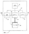
図3は、図2に示されたMSP 40A及び40Bの主要構成部を示す概略図である。 MSP 40A及び40Bはそれぞれ、制御プロセッサ70、制御バス72、TDM物理的インターフェース74、 TDM時間スイッチ76、 ATMインターフェース78、及び、複数のサービス回路80を含んでいる。 第一のインターフェース・バス82はTDM物理的インターフェース74をTDM時間スイッチ76に接続する。 第二のインターフェース・バス84はTDM時間スイッチ76をATMインターフェース78に接続する。
【0026】
制御メッセージとTDMデータはMSP 40A及び40Bによって、それぞれのスイッチファブリック・インターフェース28A及び28Bを介して受け取られる。 スイッチファブリック・インターフェースの光形式出力はTDM物理的インターフェース74で電気形式に変換され、インターフェース・バス82を介してTDM時間スイッチ76へ送られる。 制御メッセージは制御バス72を介して制御プロセッサ70に繋げられる。 制御プロセッサ70は、TDM交換装置10の計算モジュール16から送られてきた制御メッセージを受け、それに応えることによってトランク周辺装置30(図1)をエミュレートする。 制御プロセッサ70はまた、 計算モジュール16から送られてきた制御メッセージに応じて、或いは、予め決められた条件を見出すことによって、この分野では周知の方法によってPCMデータの交換を制御する。それにより、PCMデータは要求通りサービス回路80のうちの1つに繋げられる。 サービス回路80は、トーン検出、トーン生成、及びエコー・キャンセラなど、技術的に周知の全ての機能を実行する。サービス回路80の何れか1つを要求するPCMデータがあれば、 TDM時間スイッチは、PCMデータをインターフェース・バス84を介してATMインターフェース78へ差し向ける前にサービス回路に向ける。TDM時間スイッチ76で実行されるデータ交換は全て制御プロセッサ70の制御下で行われる。
【0027】
ATMインターフェース78で受け取られたPCMデータはATMバックボーン・ネットワーク45(図2)を通して転送するためのATMセルに変換される。 ATMインターフェース78は、各呼のデータに関するサービス品質(QOS)を決める。 ATMインターフェース78はまた、各ATMセルに添付する5バイトのATMセル・ヘッダーを作成する。 電話用途の場合、 ATMインターフェース78は、通常、2つのサービス品質(QOS)タイプのうちの1つを識別し、そのQOSタイプに準拠したATMセルにパックされるように適当なチャネルへデータを送る。 CBR(固定ビット・レート;Constant Bit Rate)の音声級データの場合、標準的なATM適用レイヤー・サービス 1(AAL-1)を使うPCM/ATM適応モジュール(図示せず)に接続されたチャネルにデータは繋がれる。モジュールは、その固定ビット・レート音声級データをATMペイロードに変換し、標準的な48バイトATMペイロード・セルにそのデータをロードする。 48バイト・ペイロードは、その後、5バイトのセル・ヘッダと組合わされて53バイトのATMセルとなり、シリアル・リンク・インターフェース86を通してMSPから送り出される。 VBR(可変ビット・レート;Variable Bit Rate)もしくはUBR(無規定ビット・レート;Unspecified Bit Rate)データの場合、標準的なATM適用レイヤー・サービス 5(AAL-5)を使うPCM/ATM適応モジュール(図示せず)に接続されたチャネルにデータは繋がれる。 モジュールは、そのVBR或いはUBRデータをATMペイロードに変換し、標準的な48バイトATMペイロード・セルにそのデータをロードする。 48バイト・ペイロードは、その後、5バイトのセル・ヘッダと組合わされて53バイトのATMセルとなり、シリアル・リンク・インターフェース86でMSP40A及び40Bから転送される。
【0028】
当業者であれば、TDM交換装置10へ接続するためにATMセルをPCMデータに変換する逆のプロセスもMSPが同時に実行することに気付くであろう。 プロセスにおいては、ATMセルのペイロードはアンロードされ、光形式のPCMデータに変換され、そして、シリアル・リンク28A及び28Bへ出力される。 この技術に通じた人であれば、MSP40A及び40Bが、デジタル・トランク・コントローラをエミュレートするために必要な機能を実行するだけでなく、上記3つの米国特許出願に詳述される、ATMバックボーン・ネットワークにおける仮想チャネル・コネクションの設定及び制御に関する機能も同様に実行することを理解するであろう。
【0029】
上記実施例における変更や改良は、当業者に明らかなことは確かである。 従って、この発明の範囲はひとえに上記の請求項により規定されるものとする。
【0030】
【発明の効果】
この発明によるとTDM交換装置とATMバックボーン・ネットワークを直接接続することが可能となる。
【図面の簡単な説明】
【図1】 従来技術によるATMバックボーン・ネットワーク・インターフェースを備えた交換電話網におけるTDM交換装置の配置を示した概略図。
【図2】 TDM交換装置とATMバックボーン・ネットワークの間のATMによる直接接続を実現するために用いられるインターフェースのアーキテクチャを示す概略図。
【図3】 インターフェースの内部アーキテクチャを示す概略図。
【符号の説明】
10 TDM交換装置
15 スイッチファブリック(Switch fabric)
16 計算モジュール
20 ライン周辺装置
21 加入者線
28 スイッチファブリック・インターフェース
40 マルチサービス・プラットフォーム(MSP)
45 ATMバックボーン・ネットワーク
50 TDM交換装置[0001]
BACKGROUND OF THE INVENTION
The present invention relates to the field of telecommunications, and more particularly to an apparatus and method for trunking a time division multiplexing (TDM) switch in a switched telephone network directly to an asynchronous transfer mode (ATM) facility.
[0002]
[Prior art]
ATM switching equipment is commonly used by telecommunications carriers for data transfer, but is more frequently used to carry bearer traffic for telephone calls between switches in the public telephone network (PSTN). Enabling connectivity to ATM equipment in the PSTN enables ATM equipment providers to expand their customer base and, as a result, improve return on investment in ATM network infrastructure. Call routing in ATM facilities is very flexible because ATM routing is not constrained by the hierarchical structure that governs the current call routing in the PSTN. In addition, ATM facilities can be owned and operated at a relatively lower cost than traditional TDM facilities. In addition, the ATM switch requires a smaller installation area than the TDM switch, so that the maintenance cost of the mechanical equipment can be reduced.
[0003]
One way to enable a PSTN switch to use an ATM trunk network to enable calls between switches is US patent application Ser. No. 09 / 158,855 (September 23, 1998) “TRNSIT TRUNK SUBNETWORK SYSTEM. Line Subnetwork System) ”, the disclosure of which is incorporated herein by reference. The trunk subnetwork includes an interface between a TDM switching device called a multi-service platform (MSP) and an ATM backbone network. MSP converts pulse code modulation (PCM) data to ATM cells and vice versa. MSP also maps TDM trunks to ATM Virtual Channel Connections (VCCs) so that bearer traffic can be forwarded between TDM switches in the trunk subnetwork through the ATM backbone network. enable.
[0004]
The trunk line subnetwork has been formed as a countermeasure against congestion in the PSTN, because in the trunk line subnetwork, a communication route between TDM switching apparatuses can be set through the ATM backbone network. The trunk line subnetwork also allows dynamic bandwidth management by controlling VCC allocation in a responsive and predictive manner to ensure efficient use of bearer traffic. Therefore, ATM backbone network equipment is reserved only in proportion to demand, and other functions such as data transfer from other networks can use the surplus capacity of the network.
[0005]
ATM equipment providers are also experiencing demand for access to ATM equipment by competing local exchange carriers (CLECs). CLEC sees ATM facilities as an effective alternative to lowering their operating costs and enabling more competitive services because ATM facilities provide call bearer traffic transfer at low cost Yes. According to the recent telecommunications regulations in force in the United States, existing regional exchange carriers (ILECs) are owned by ILEC in order for CLEC to provide local services to its customers. And access by lease of the equipment in operation must be permitted. Under such enforced arrangements, CLEC will be charged each time it accesses an ILEC facility. This fee results in a decrease in CLEC's net operating profit. As a result, we are interested in equipment that is designed to be the simplest and cheapest way to integrate a PSTN switch into an ATM backbone network.
[0006]
Therefore, there is a need for a device that requires fewer parts to connect a PSTN switch to an ATM backbone network, thereby reducing capital investment. In addition, a device for incorporating an ATM interface into the machine equipment of a TDM exchange device is required to reduce the required installation area of the system. Such integration of equipment basically reduces the required footprint and consequently the operating costs.
[0007]
[Problems to be solved by the invention]
One of the objects of the present invention is an apparatus for directly connecting a TDM to an ATM, which is a component necessary for simplifying the connection between a TDM switching apparatus and an ATM facility and connecting to an ATM backbone network. Is to provide a device that reduces the number of
[0008]
A further object of the present invention is to provide an interface device between a TDM switching device and an ATM backbone network, which requires a smaller installation area than a conventional interface device used for the same purpose.
[0009]
A further object of the present invention is an interface device between a TDM switching device and an ATM backbone network, which can be directly connected to the switch fabric interface of the TDM switching device by emulating the trunk peripheral device of the TDM switching device. Is to provide a device.
[0010]
It is a further object of the present invention to provide an interface device between a TDM exchange and an ATM backbone network that can interact with the computation module of the TDM exchange without modifying the computation module or message transmission system. Is to provide.
[0011]
[Means for Solving the Problems]
In accordance with the above-described problems, the present invention provides an apparatus comprising the following for directly trunk-connecting a TDM switching apparatus and an ATM backbone network. That is, an interface designed to transfer ATM cells to the backbone network and connect to one ATM link to receive ATM cells from the ATM backbone network, as well as PCM data to the TDM switch. Providing a device configured as an interface that can be connected to at least one serial link to transfer to and receive PCM data from the switch body of a TDM switch It is. The interface is also designed to emulate the trunk peripheral of the TDM switch, so that the TDM switch computing module uses the protocol to communicate with the compute module specific trunk peripheral. I can communicate.
[0012]
Therefore, the present invention provides a simple interface device between the TDM switching device and the ATM equipment, instead of the conventional interface. The present invention further enables the interface to be integrated into the TDM switch infrastructure. This allows for a simple interface with relatively few parts and allows for transfer to ATM facilities with less money.
[0013]
The present invention also provides a method for directly trunking a TDM switching apparatus and an ATM backbone network as follows. The method includes forming an interface that can convert PCM data to ATM cells and vice versa, and that the interface communicates with the switch's compute module using the switch's native message protocol. It is possible. Thereby, the interface emulates the trunk peripheral of the TDM switch. The interface is directly connected to the serial link of the switch fabric interface of the TDM switch, allowing a direct trunk connection between the TDM switch and the ATM backbone network.
[0014]
Thus, the present invention is also suitable for a method for providing a direct ATM trunk connection between a TDM switch and an ATM backbone network. A direct ATM trunk connection reduces the number of components required to connect the TDM switch to the ATM backbone network. This requires less money to use ATM facilities to capture bearer traffic from the PSTN. Also, since the interface occupies less space, it can be incorporated into the TDM exchange equipment.
[0015]
DETAILED DESCRIPTION OF THE INVENTION
The present invention is suitable for an apparatus and method for interfacing a TDM switching apparatus and an ATM facility in a switched telephone network, and enables a direct connection between TDM and ATM.
[0016]
FIG. 1 shows a prior
[0017]
The line side of the
[0018]
The trunk side of the
[0019]
[0020]
[0021]
FIG. 2 is a schematic diagram of a preferred embodiment of the present invention, showing that an ATM interface can be physically incorporated into the
[0022]
To implement the interface configuration shown in FIG. 2,
[0023]
As shown in FIG. 1, the
[0024]
In order to simplify the conversion table of the
[0025]
FIG. 3 is a schematic diagram showing the main components of the
[0026]
Control messages and TDM data are received by
[0027]
PCM data received at the
[0028]
Those skilled in the art will realize that the MSP also performs the reverse process of converting ATM cells to PCM data for connection to the
[0029]
Certainly, changes and improvements in the above embodiments will be apparent to those skilled in the art. Accordingly, the scope of the invention should be defined solely by the following claims.
[0030]
【The invention's effect】
According to the present invention, it is possible to directly connect a TDM switching apparatus and an ATM backbone network.
[Brief description of the drawings]
FIG. 1 is a schematic diagram showing the arrangement of a TDM switching apparatus in a switched telephone network having an ATM backbone network interface according to the prior art.
FIG. 2 is a schematic diagram illustrating the architecture of an interface used to implement a direct ATM connection between a TDM switching device and an ATM backbone network.
FIG. 3 is a schematic diagram showing the internal architecture of the interface.
[Explanation of symbols]
10 TDM switching equipment
15 Switch fabric
16 Calculation module
20 line peripheral
21 Subscriber line
28 Switch fabric interface
40 Multiservice platform (MSP)
45 ATM backbone network
50 TDM changer
Claims (17)
パケットベース・ネットワークに対してパケットベースのデータを送受信するようにされ、かつ、TDM交換装置のスイッチファブリックとの間でパルス符号変調(PCM)データを送受信するよう少なくとも1つのシリアル・リンクに接続することができ、PCMデータをパケットベースのデータに変換し、また、その逆の変換を行う、インターフェースを備え、
前記インターフェースは、TDM交換装置のデジタル・トランク・コントローラをエミュレートして、TDM交換装置の計算モジュールがデジタル・トランク・コントローラと交信するためのネイティブのプロトコルを使って該インターフェースと交信するようにされ、
前記計算モジュールから制御メッセージを受信して所望のトランクメンバへの呼のルーティングをすることに応答して、前記インターフェースは、所望のトランクメンバをパケットベース・ネットワークを介して仮想コネクションの確立にマップするようにされる、装置。A device for direct trunk connection between a time division multiplexing (TDM) switch and a packet-based network,
Connect to at least one serial link to send and receive packet-based data to and from packet-based networks and to send and receive pulse code modulation (PCM) data to and from the switch fabric of the TDM switch It has an interface that converts PCM data to packet-based data and vice versa
The interface emulates a TDM switch digital trunk controller so that the TDM switch compute module communicates with the interface using a native protocol for communicating with the digital trunk controller. ,
In response to receiving a control message from the computing module and routing a call to a desired trunk member, the interface maps the desired trunk member to the establishment of a virtual connection over a packet-based network. Made device.
PCMデータをパケットベースのデータに変換し、また、その逆の変換ができるようにされ、さらに、交換機のネイティブのメッセージ・プロトコルを使って、交換機の計算モジュールと交信し、TDM交換装置のデジタル・トランク・コントローラをエミュレートすることができるようにされた、インターフェースを提供するステップと、
該インターフェースをTDM交換装置及びパケットベース・ネットワークのスイッチファブリックのシリアル・リンクに直接接続して、TDM交換装置とパケットベース・ネットワークの間の直接トランク接続を可能にするステップとを含み、
前記計算モジュールから制御メッセージを受信して所望のトランクメンバへの呼のルーティングをすることに応答して、前記インターフェースは、所望のトランクメンバをパケットベース・ネットワークを介して仮想コネクションの確立にマップするようにされる、方法。A method for providing a direct trunk connection between a DM switch and a packet-based network, comprising:
PCM data can be converted to packet-based data and vice versa, and the switch's native message protocol can be used to communicate with the switch's computing module and the TDM switch's digital Providing an interface adapted to emulate a trunk controller ;
Directly connecting the interface to the serial link of the switch fabric of the TDM switch and packet-based network to allow direct trunk connection between the TDM switch and packet-based network;
In response to receiving a control message from the computing module and routing a call to a desired trunk member, the interface maps the desired trunk member to the establishment of a virtual connection over a packet-based network. Done, the way.
パケットベース・ネットワークに対してパケットベースのデータを送受信するようにされ、かつ、TDM交換装置のスイッチファブリックとPCMデータを送受信するために、少なくとも一つのシリアル・リンクとの接続をできるようにされ、PCMデータをパケットベースのデータに変換し、また逆の変換も行い、TDM交換装置のデジタル・トランク・コントローラをエミュレートして、TDMの呼に応じた仮想コネクションを制御するためにパケットベース・ネットワークに接続している対応したインターフェースと交信できるようにされた、インターフェースとを備え、
所望のトランクメンバへの呼のルーティングをする制御メッセージに応答して、前記インターフェースは、さらに、所望のトランクメンバをパケットベース・ネットワークを介して仮想コネクションの確立にマップするようにされる、装置。A device for direct trunk connection between a TDM switching device and a packet-based network,
Packet-based data is sent to and received from the packet-based network, and at least one serial link is connected to send and receive PCM data to the switch fabric of the TDM switch, A packet-based network to convert PCM data to packet-based data and vice versa, emulate a TDM switch digital trunk controller to control virtual connections in response to TDM calls An interface adapted to communicate with the corresponding interface connected to the
In response to a control message routing a call to a desired trunk member, the interface is further adapted to map the desired trunk member to establishment of a virtual connection over a packet-based network.
PCMデータをパケットベースのデータに、また、その逆の変換ができるようにされ、該インターフェースが、TDM交換装置のデジタル・トランク・コントローラをエミュレートし、また、パケットベース・ネットワークに接続している他のインターフェースと交信できるようにされて、TDMの呼に応じた仮想コネクションを制御するインターフェースを提供するステップと、
TDM交換装置とパケットベース・ネットワークの間の直接トランク接続を可能にするために、該インターフェースをTDM交換装置のスイッチファブリックのシリアル・リンクに直接接続するステップと、を含み、
前記計算モジュールから制御メッセージを受信して所望のトランクメンバへの呼のルーティングをすることに応答して、前記インターフェースは、所望のトランクメンバをパケットベース・ネットワークを介して仮想コネクションの確立にマップするようにされる、方法。A method for providing a direct trunk connection between a TDM switch and a packet-based network comprising:
PCM data can be converted to packet-based data and vice versa, the interface emulates a TDM switch digital trunk controller and is connected to a packet-based network Providing an interface adapted to communicate with other interfaces to control virtual connections in response to TDM calls;
Directly connecting the interface to a serial link of the switch fabric of the TDM switch to allow a direct trunk connection between the TDM switch and the packet-based network;
In response to receiving a control message from the computing module and routing a call to a desired trunk member, the interface maps the desired trunk member to the establishment of a virtual connection over a packet-based network. Done, the way.
Applications Claiming Priority (2)
| Application Number | Priority Date | Filing Date | Title |
|---|---|---|---|
| US22002098A | 1998-12-23 | 1998-12-23 | |
| US09/220020 | 1998-12-23 |
Publications (3)
| Publication Number | Publication Date |
|---|---|
| JP2000224196A JP2000224196A (en) | 2000-08-11 |
| JP2000224196A5 JP2000224196A5 (en) | 2007-02-22 |
| JP4484290B2 true JP4484290B2 (en) | 2010-06-16 |
Family
ID=22821717
Family Applications (1)
| Application Number | Title | Priority Date | Filing Date |
|---|---|---|---|
| JP36012099A Expired - Lifetime JP4484290B2 (en) | 1998-12-23 | 1999-12-20 | Apparatus and method for directly connecting a terminal station to an ATM |
Country Status (4)
| Country | Link |
|---|---|
| US (1) | US7269167B2 (en) |
| EP (1) | EP1014749A3 (en) |
| JP (1) | JP4484290B2 (en) |
| CA (1) | CA2290304C (en) |
Families Citing this family (7)
| Publication number | Priority date | Publication date | Assignee | Title |
|---|---|---|---|---|
| WO2001054354A1 (en) * | 2000-01-20 | 2001-07-26 | Mci Worldcom, Inc. | Intelligent network and method for providing voice telephony over atm and point-to-multipoint connectivity |
| US6819678B2 (en) * | 2000-12-21 | 2004-11-16 | Nortel Networks Limited | Interworking of dissimilar packet networks for telephony communications |
| KR100429263B1 (en) * | 2001-10-31 | 2004-04-29 | 엘지전자 주식회사 | Method and apparatus for preventing of mobile terminal |
| US6807273B2 (en) * | 2001-11-30 | 2004-10-19 | David Matthew Smith | Method and apparatus for bypassing the common control and switch matrix of a digital switching system for telecommunications networks |
| ES2349122T3 (en) | 2002-05-03 | 2010-12-28 | Cedar Point Communications, Inc. | COMMUNICATIONS SWITCHING ARCHITECTURE. |
| US7869424B2 (en) * | 2002-07-01 | 2011-01-11 | Converged Data Solutions Inc. | Systems and methods for voice and data communications including a scalable TDM switch/multiplexer |
| US7657018B2 (en) * | 2004-10-22 | 2010-02-02 | Smith David M | Method and system for combining a conversion between time-division multiplexed digital signals and packetized digital signals with a switching system interface |
Family Cites Families (16)
| Publication number | Priority date | Publication date | Assignee | Title |
|---|---|---|---|---|
| JP2890348B2 (en) * | 1990-11-30 | 1999-05-10 | 富士通株式会社 | Telephone subscriber accommodation in broadband networks. |
| US5327421A (en) * | 1992-11-06 | 1994-07-05 | At&T Bell Laboratories | Apparatus for interfacing between telecommunications call signals and broadband signals |
| JP2518515B2 (en) * | 1993-05-27 | 1996-07-24 | 日本電気株式会社 | High-speed connection setup packet switch |
| US5452297A (en) * | 1993-12-20 | 1995-09-19 | At&T Corp. | Access switches for large ATM networks |
| JP3142433B2 (en) * | 1993-12-29 | 2001-03-07 | 株式会社東芝 | Bridge device and bridge connection method |
| US5528592A (en) * | 1994-01-27 | 1996-06-18 | Dsc Communications Corporation | Method and apparatus for route processing asynchronous transfer mode cells |
| US5483527A (en) * | 1994-12-21 | 1996-01-09 | At&T Corp. | Terminal adapter for interfacing an ATM network with a STM network |
| US5568475A (en) * | 1994-12-21 | 1996-10-22 | Lucent Technologies Inc. | ATM network architecture employing an out-of-band signaling network |
| DE19502414C1 (en) * | 1995-01-26 | 1996-02-08 | Siemens Ag | Rapid through switching of virtual connections in ATM communication system |
| US5623491A (en) * | 1995-03-21 | 1997-04-22 | Dsc Communications Corporation | Device for adapting narrowband voice traffic of a local access network to allow transmission over a broadband asynchronous transfer mode network |
| US5889773A (en) * | 1996-11-27 | 1999-03-30 | Alcatel Usa Sourcing, L.P. | Method and apparatus for placing time division multiplexed telephony traffic into an asynchronous transfer mode format |
| US6172973B1 (en) * | 1997-09-17 | 2001-01-09 | Nortel Networks Limited | Apparatus and method for reducing delay for voice over ATM using co-located switches |
| US6256308B1 (en) * | 1998-01-20 | 2001-07-03 | Telefonaktiebolaget Lm Ericsson | Multi-service circuit for telecommunications |
| US6195714B1 (en) * | 1998-06-08 | 2001-02-27 | Nortel Networks Limited | System for transferring STM calls through ATM network by converting the STM calls to ATM and vice versa at the edge nodes of ATM network |
| US6282194B1 (en) * | 1998-09-23 | 2001-08-28 | Nortel Networks Limited | Transit trunk subnetwork system |
| US6141342A (en) * | 1998-12-02 | 2000-10-31 | Nortel Networks Corporation | Apparatus and method for completing inter-switch calls using large trunk groups |
-
1999
- 1999-11-23 CA CA002290304A patent/CA2290304C/en not_active Expired - Lifetime
- 1999-12-15 EP EP99310083A patent/EP1014749A3/en not_active Withdrawn
- 1999-12-20 JP JP36012099A patent/JP4484290B2/en not_active Expired - Lifetime
-
2003
- 2003-09-08 US US10/657,551 patent/US7269167B2/en not_active Expired - Lifetime
Also Published As
| Publication number | Publication date |
|---|---|
| CA2290304A1 (en) | 2000-06-23 |
| US7269167B2 (en) | 2007-09-11 |
| CA2290304C (en) | 2009-03-17 |
| US20040081174A1 (en) | 2004-04-29 |
| JP2000224196A (en) | 2000-08-11 |
| EP1014749A2 (en) | 2000-06-28 |
| EP1014749A3 (en) | 2002-11-20 |
Similar Documents
| Publication | Publication Date | Title |
|---|---|---|
| US6169735B1 (en) | ATM-based distributed virtual tandem switching system | |
| US6496508B1 (en) | Communication system architecture and method of establishing a communication connection therein | |
| US6069947A (en) | Communication system architecture and operating protocol therefor | |
| US20050254496A1 (en) | Broadband telecommunications system | |
| KR100683012B1 (en) | System and method for providing pots services in dsl environment in event of failures | |
| CA2272311C (en) | Subscriber access apparatus capable of adapting all of analog communication access network, isdn access network and xdsl access network to atm core network | |
| JP4484290B2 (en) | Apparatus and method for directly connecting a terminal station to an ATM | |
| KR100738293B1 (en) | System and method for providing voice and/or data services | |
| US7212518B2 (en) | Combining narrowband applications with broadband transport | |
| JP4293730B2 (en) | Communications system | |
| KR100327161B1 (en) | apparatus for ADSL subscriber matching in switching system | |
| KR100325060B1 (en) | Full electronic switching system capable of accepting adsl subscribers | |
| KR100378367B1 (en) | Interworking method between narrow band network and atm network | |
| Kim et al. | SS No. 7 based N-ISDN interworking in ATM switching system | |
| Diesel | ISDN CENTRAL OFFICE SWITCH MANUFACTURERS'PERSPECTIVE | |
| KR20020010975A (en) | Method and Device for Interlocking PABX through ATM Network |
Legal Events
| Date | Code | Title | Description |
|---|---|---|---|
| A521 | Written amendment |
Free format text: JAPANESE INTERMEDIATE CODE: A523 Effective date: 20061220 |
|
| A621 | Written request for application examination |
Free format text: JAPANESE INTERMEDIATE CODE: A621 Effective date: 20061220 |
|
| A977 | Report on retrieval |
Free format text: JAPANESE INTERMEDIATE CODE: A971007 Effective date: 20090917 |
|
| A131 | Notification of reasons for refusal |
Free format text: JAPANESE INTERMEDIATE CODE: A131 Effective date: 20090929 |
|
| A521 | Written amendment |
Free format text: JAPANESE INTERMEDIATE CODE: A523 Effective date: 20091211 |
|
| TRDD | Decision of grant or rejection written | ||
| A01 | Written decision to grant a patent or to grant a registration (utility model) |
Free format text: JAPANESE INTERMEDIATE CODE: A01 Effective date: 20100302 |
|
| A01 | Written decision to grant a patent or to grant a registration (utility model) |
Free format text: JAPANESE INTERMEDIATE CODE: A01 |
|
| A61 | First payment of annual fees (during grant procedure) |
Free format text: JAPANESE INTERMEDIATE CODE: A61 Effective date: 20100323 |
|
| R150 | Certificate of patent or registration of utility model |
Free format text: JAPANESE INTERMEDIATE CODE: R150 Ref document number: 4484290 Country of ref document: JP Free format text: JAPANESE INTERMEDIATE CODE: R150 |
|
| FPAY | Renewal fee payment (event date is renewal date of database) |
Free format text: PAYMENT UNTIL: 20130402 Year of fee payment: 3 |
|
| FPAY | Renewal fee payment (event date is renewal date of database) |
Free format text: PAYMENT UNTIL: 20130402 Year of fee payment: 3 |
|
| FPAY | Renewal fee payment (event date is renewal date of database) |
Free format text: PAYMENT UNTIL: 20140402 Year of fee payment: 4 |
|
| R250 | Receipt of annual fees |
Free format text: JAPANESE INTERMEDIATE CODE: R250 |
|
| R250 | Receipt of annual fees |
Free format text: JAPANESE INTERMEDIATE CODE: R250 |
|
| R250 | Receipt of annual fees |
Free format text: JAPANESE INTERMEDIATE CODE: R250 |
|
| R250 | Receipt of annual fees |
Free format text: JAPANESE INTERMEDIATE CODE: R250 |
|
| R250 | Receipt of annual fees |
Free format text: JAPANESE INTERMEDIATE CODE: R250 |
|
| R250 | Receipt of annual fees |
Free format text: JAPANESE INTERMEDIATE CODE: R250 |
|
| R250 | Receipt of annual fees |
Free format text: JAPANESE INTERMEDIATE CODE: R250 |
|
| EXPY | Cancellation because of completion of term |