JP4482921B2 - Water discharge device - Google Patents
Water discharge device Download PDFInfo
- Publication number
- JP4482921B2 JP4482921B2 JP2000281476A JP2000281476A JP4482921B2 JP 4482921 B2 JP4482921 B2 JP 4482921B2 JP 2000281476 A JP2000281476 A JP 2000281476A JP 2000281476 A JP2000281476 A JP 2000281476A JP 4482921 B2 JP4482921 B2 JP 4482921B2
- Authority
- JP
- Japan
- Prior art keywords
- valve
- button
- water
- open
- discharge device
- Prior art date
- Legal status (The legal status is an assumption and is not a legal conclusion. Google has not performed a legal analysis and makes no representation as to the accuracy of the status listed.)
- Expired - Fee Related
Links
Images


Description
【0001】
【発明の属する技術分野】
本発明は、止水機能付吐水装置に関する。
【0002】
【従来の技術】
従来の吐水制御装置としては、図6に見られるように、台所用止水機能付ハンドシャワータイプのシングルレバー混合栓が知られている。
【0003】
シャワーヘッド1は、下部先端の前面に切替ボタン8が設けられ、切替ボタン8により、吐水形態を切り替えるように構成してある。また、上部には、開閉ボタン6が設けられ、シャワーヘッド1先端での止水を可能としている。
【0004】
【発明が解決しようとする課題】
しかし、従来の吐水装置では、切替機能と開閉機能を上下2段に構成する必要があるため、シャワーヘッドが大きくなりすぎるという問題があった。
【0005】
そのため、シャワーヘッドをシングルレバー本体から引き出した際、片手で開閉ボタンと切替ボタンを操作できないという問題もあった。
【0006】
本発明は、上記課題を解決するためになされたもので、本発明の目的は、切替ボタンと開閉ボタンを散水板とを具備し、切替ボタンと連繋した弁体の移動で2つの弁孔を選択的に開閉し、散水板の底面から吐水される湯水の吐水形態を切替可能とし、開閉ボタンと連繋した第一の開閉弁により止水を可能にした止水機能付吐水装置において、片手で操作できるコンパクトで安全な止水機能付吐水装置を供給することにある。
【0007】
【課題を解決するための手段】
上記の課題を解決するため本発明の吐水装置は、切替ボタンと開閉ボタンと散水板とをシャワーヘッドに具備し、前記切替ボタンと連繋した弁体の移動で2つの弁孔を選択的に開閉し、前記散水板の底面から吐水される湯水の吐水形態を切替可能とし、前記開閉ボタンと連繋した第一の開閉弁により止水を可能にした吐水装置において、前記開閉ボタンを前記シャワーヘッドの前面に、前記切替ボタンを前記開閉ボタンから水平方向の前記シャワーヘッドの側面に配置したことを特徴とする。
このように、開閉ボタンと切替ボタンとを上下2段にせず同じ高さに配置したため、シャワーヘッド部をコンパクトに構成することができ、シャワーヘッドを操作する際、片手で、吐水の開閉と吐水の切替を操作でき、便利である。
【0008】
また、前記第一の開閉弁は、開閉バルブが下流側の弁座に付勢された状態でガイド内に嵌装されており、前記開閉ボタンを押すとこの開閉ボタンに連結された軸が上流側に押され、前記開閉バルブを前記弁座より上流側に押して吐水可能であることを特徴とする。
従って、開閉バルブの開閉の際、上流側の水圧がかからないことにより、開閉ボタンの操作力が低く抑えられるため、第一の開閉弁をコンパクトにしてシャワーヘッドに組み込むことができる。
【0009】
前記吐水装置の上流側水路に減圧機能を有する第二の開閉弁を具備したため、シングルレバー本体バルブとシャワーヘッドの間が一定圧力以内に減圧されるため、安全に先端で止水することができる。
【0010】
【発明の実施の形態】
以上説明した本発明の構成・作用を一層明らかにするために、以下本発明の好適な実施例について説明する。
【0011】
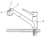
図1、2、3を参照にして、本発明の第一の実施例に係わる吐水制御装置の構成について説明する。図1は、本実施の形態に係わる吐水装置を台所用ハンドシャワー装置として用いた場合であり、シャワーヘッド1には、基端部にシャワーホース2が接続され、減圧機構を有する第二の開閉弁3と螺着してあり、また第二の開閉弁3は、シングルレバー本体4の下部に装着された連結管5に螺着されている。
【0012】
第二の開閉弁3は、特開平10−295577公報に示された水道用定圧弁を第二の開閉弁3として設け、第一の開閉弁7の開閉操作によってシャワーホース2内に生じる圧力変動により開閉動作が制御され、止水・流量調整及び圧力調整を行う。
【0013】
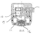
シャワーヘッド1は、開閉ボタン6と開閉ボタン6に連繋して開閉する第一の開閉弁7と、切替ボタン8と切替ボタン8に連繋して移動し、2つの弁孔17を交互に開閉する弁体10と、シャワー吐水口11,整流吐水口12により構成されている。この際、開閉ボタン6と第一の開閉弁7は、切替ボタン8と弁体10に対して、上部に構成することなく、水平方向に構成し、シャワーヘッド高さが高くなることを防いである。
【0014】
第一の開閉弁7は、開閉バルブ13が、ガイド14とパッキン15により、上流側水路16と水密され、バネ20により下流側に付勢した状態で嵌装されており、開閉バルブ13の開閉の際、上流側の水圧がかからないように構成してある。
【0015】
今、開閉ボタン6を押すと、開閉ボタンに連結された軸18が上流側に押され、開閉バルブ13を弁座19より押し上げ、湯水が吐水する。
【0016】
この際、開閉バルブ13の開閉の際、上流側の水圧がかからないように構成してあることにより、開閉ボタン6の操作力が低く抑えられる。
【0017】
また、切替ボタン8を押すと、切替ボタン8に連繋した球状の弁体10が、弁孔17上を交互に移動して開閉し、湯水が開かれた弁穴17をとおり、シャワー吐水口11または整流吐水口12から吐水する。
【0018】
その後、再度開閉ボタン6を押すと、開閉ボタン6に連結された軸18が下流側に戻り、開閉バルブ13は、バネ20の付勢により、弁座19に当接してシールし、止水する。
【0019】
図4は、第一の開閉弁7の逃がし機構について説明したものであり、今上流側の水圧がある一定圧力を越えると、開閉バルブ13に設けられた面21を水圧が押し、バネ20の付勢に抗して開閉バルブ13を押し上げる。これにより、上流側の水が下流側に吐水し、異常な昇圧を防ぐことが出来る。
【0020】
図5は、逃がし弁22を設けたものであり、今上流側の水圧がある一定圧力を越えると、球状の逃がし弁22が水圧によりバネ23の付勢に抗して開き、第一の開閉弁7の内部の通水路9を湯水が抜け、上流側の水が下流側に吐水し、異常な昇圧を防ぐことが出来る。
【0021】
上記実施例は、台所ハンドシャワータイプのシングルレバーに限定することなく、洗面所用の洗髪機能付洗面化粧台用の水栓にも応用することができる。
【0022】
また、以上の実施例では、開閉ボタンをシャワーヘッドの前面に、切替ボタンをャワーヘッドの側面に配置したが、開閉ボタンをシャワーヘッドの側面に、切替ボタンをャワーヘッドの前面に配置してもよく、開閉ボタンと、切替ボタンを略対向するシャワーヘッドの側面に、配置してもよい。
【0023】
【発明の効果】
本発明によれば、開閉ボタンと切替ボタンとを上下2段にせず同じ高さに配置したため、シャワーヘッド部をコンパクトに構成することができ、シャワーヘッドを操作する際、片手で、吐水の開閉と吐水の切替を操作でき、便利である。
【0024】
また、第一の開閉弁の開閉バルブの開閉の際、上流側の水圧がかからない構成とすることにより、開閉ボタンの操作力が低く抑えられるため、第一の開閉弁をコンパクトにしてシャワーヘッドに組み込むことができる。
【0025】
また、上流側水路に減圧機能を有する第二の開閉弁を具備したため、安全に先端の第一の開閉弁により止水できる。
【図面の簡単な説明】
【図1】本発明の第一の実施例である台所ハンドシャワー装置の側面図
【図2】第一の実施例のシャワーヘッド断面図
【図3】図2のA〜A断面図
【図4】第一の実施例の逃がし機構詳細図
【図5】第一の実施例の逃がし弁を追加したシャワーヘッド断面図
【図6】従来の台所ハンドシャワー装置の側面図
【符号の説明】
1:シャワーヘッド 2:シャワーホース
3:第二の開閉弁 4:シングルレバー本体
5:連結管 6:開閉ボタン
7:第一の開閉弁 8:切替ボタン
9:通水路 10:弁体
11:シャワー吐水口 12:整流吐水口
13:開閉バルブ 14:ガイド
15:パッキン 16:上流側水路
17:弁孔 18:軸
19:弁座 20:バネ
21:面 22:逃がし弁
23:バネ[0001]
BACKGROUND OF THE INVENTION
The present invention relates to a water discharger with a water stop function.
[0002]
[Prior art]
As a conventional water discharge control device, as shown in FIG. 6, a hand shower type single lever mixer tap with a water stop function for a kitchen is known.
[0003]
The shower head 1 is provided with a
[0004]
[Problems to be solved by the invention]
However, in the conventional water discharging apparatus, since the switching function and the opening / closing function need to be configured in two upper and lower stages, there is a problem that the shower head becomes too large.
[0005]
Therefore, there is a problem that when the shower head is pulled out from the single lever body, the open / close button and the switching button cannot be operated with one hand.
[0006]
The present invention has been made to solve the above-described problems. An object of the present invention is to provide a switching button, an opening / closing button, a water spray plate, and two valve holes by moving a valve body connected to the switching button. In a water discharge device with a water stop function that can be selectively opened and closed, the water discharge form of hot water discharged from the bottom surface of the water spray plate can be switched, and water can be stopped by the first on-off valve linked to the open / close button. It is to supply a compact and safe water discharge device with a water stop function.
[0007]
[Means for Solving the Problems]
Water discharger of the present invention for solving the aforementioned problem, the switching button and the closing button sprinkler plate provided in the shower head, selectively open and close two valve hole by moving the valve body in tandem with the switching button and the hot water of the water discharge form spouted from the bottom of the shower plate and can be switched, in the water discharge device that enables waterproofing by a first on-off valve in tandem with the opening and closing button, the closing button of the showerhead The switching button is disposed on the side surface of the shower head in the horizontal direction from the open / close button .
In this way, since the opening / closing button and the switching button are arranged at the same height without being arranged in two upper and lower stages, the shower head can be configured compactly, and when operating the shower head, the opening / closing and discharging of the water can be performed with one hand. It is convenient because it can be operated.
[0008]
The first opening / closing valve is fitted in the guide with the opening / closing valve biased to the downstream valve seat, and when the opening / closing button is pressed, the shaft connected to the opening / closing button is upstream. It is possible to discharge water by pushing the open / close valve to the upstream side from the valve seat.
Accordingly, since the upstream water pressure is not applied when the on-off valve is opened / closed, the operating force of the on-off button can be kept low. Therefore, the first on-off valve can be made compact and incorporated in the shower head.
[0009]
Since the second on-off valve having a pressure reducing function is provided in the upstream water channel of the water discharge device, the pressure between the single lever main body valve and the shower head is reduced within a certain pressure, so that water can be safely stopped at the tip. .
[0010]
DETAILED DESCRIPTION OF THE INVENTION
In order to further clarify the configuration and operation of the present invention described above, preferred embodiments of the present invention will be described below.
[0011]
The configuration of the water discharge control device according to the first embodiment of the present invention will be described with reference to FIGS. FIG. 1 shows a case in which the water discharge device according to the present embodiment is used as a hand shower device for kitchens. A shower hose 2 is connected to the base end of the shower head 1 and has a pressure reducing mechanism. The second open /
[0012]
The second on-off
[0013]
The shower head 1 moves in conjunction with the opening /
[0014]
The first on-off valve 7 is fitted in such a manner that the on-off
[0015]
Now, when the open /
[0016]
At this time, since the upstream water pressure is not applied when the opening /
[0017]
When the
[0018]
Thereafter, when the opening /
[0019]
FIG. 4 illustrates the relief mechanism of the first on-off valve 7. When the upstream water pressure exceeds a certain pressure, the water pressure pushes the
[0020]
FIG. 5 shows a case where a
[0021]
The above embodiment is not limited to a kitchen hand shower type single lever, but can also be applied to a faucet for a bathroom vanity with a hair washing function for a bathroom.
[0022]
In the above embodiment, the open / close button is disposed on the front surface of the shower head, and the switching button is disposed on the side surface of the shower head, but the opening / closing button may be disposed on the side surface of the shower head, and the switching button may be disposed on the front surface of the shower head. The open / close button and the switching button may be disposed on the side surfaces of the shower head that are substantially opposite to each other.
[0023]
【The invention's effect】
According to the present invention, since the opening / closing button and the switching button are arranged at the same height without being arranged in two upper and lower stages, the shower head portion can be configured compactly, and when operating the shower head, opening and closing of the water discharge with one hand is possible . It is convenient to switch the water discharge.
[0024]
In addition, when opening and closing the opening and closing valve of the first opening and closing valve, the operation force of the opening and closing button can be kept low by adopting a configuration that does not apply upstream water pressure, so the first opening and closing valve is made compact and used as a shower head. Can be incorporated.
[0025]
Moreover, since the 2nd on-off valve which has a pressure reduction function was provided in the upstream water channel, water can be safely stopped by the first on-off valve at the tip .
[Brief description of the drawings]
FIG. 1 is a side view of a kitchen hand shower apparatus according to a first embodiment of the present invention. FIG. 2 is a cross-sectional view of a shower head according to the first embodiment. Detailed view of the relief mechanism of the first embodiment FIG. 5 is a sectional view of the shower head with the relief valve of the first embodiment added FIG. 6 is a side view of a conventional kitchen hand shower device
1: Shower head 2: Shower hose 3: Second open / close valve 4: Single lever body 5: Connecting pipe 6: Open / close button 7: First open / close valve 8: Switch button 9: Water passage 10: Valve body 11: Shower Water outlet 12: Rectifier water outlet 13: Opening / closing valve 14: Guide 15: Packing 16: Upstream water passage 17: Valve hole 18: Shaft 19: Valve seat 20: Spring 21: Surface 22: Relief valve 23: Spring
Claims (3)
Priority Applications (1)
| Application Number | Priority Date | Filing Date | Title |
|---|---|---|---|
| JP2000281476A JP4482921B2 (en) | 2000-09-18 | 2000-09-18 | Water discharge device |
Applications Claiming Priority (1)
| Application Number | Priority Date | Filing Date | Title |
|---|---|---|---|
| JP2000281476A JP4482921B2 (en) | 2000-09-18 | 2000-09-18 | Water discharge device |
Publications (3)
| Publication Number | Publication Date |
|---|---|
| JP2002088835A JP2002088835A (en) | 2002-03-27 |
| JP2002088835A5 JP2002088835A5 (en) | 2007-10-18 |
| JP4482921B2 true JP4482921B2 (en) | 2010-06-16 |
Family
ID=18766124
Family Applications (1)
| Application Number | Title | Priority Date | Filing Date |
|---|---|---|---|
| JP2000281476A Expired - Fee Related JP4482921B2 (en) | 2000-09-18 | 2000-09-18 | Water discharge device |
Country Status (1)
| Country | Link |
|---|---|
| JP (1) | JP4482921B2 (en) |
Families Citing this family (2)
| Publication number | Priority date | Publication date | Assignee | Title |
|---|---|---|---|---|
| US7000854B2 (en) * | 2002-11-08 | 2006-02-21 | Moen Incorporated | Pullout spray head with single-button mode selector |
| CN107350097B (en) * | 2016-05-09 | 2022-12-30 | 厦门松霖科技股份有限公司 | Take gondola water faucet of stagnant water function and water route switching function |
Family Cites Families (12)
| Publication number | Priority date | Publication date | Assignee | Title |
|---|---|---|---|---|
| JPS6187551U (en) * | 1984-11-16 | 1986-06-07 | ||
| JPH0724363A (en) * | 1993-07-09 | 1995-01-27 | Takahata Seiko Kk | Shower head |
| JP2974271B2 (en) * | 1994-10-06 | 1999-11-10 | 株式会社喜多村合金製作所 | Bathroom shower head |
| JPH10295577A (en) * | 1997-04-30 | 1998-11-10 | Toto Ltd | Water discharge controller |
| JPH10309497A (en) * | 1997-05-09 | 1998-11-24 | Kitamura Gokin Seisakusho:Kk | Shower head |
| JPH11217858A (en) * | 1998-02-02 | 1999-08-10 | Toray Ind Inc | Multidirectional valve and water cleaner |
| JP2896131B1 (en) * | 1998-03-27 | 1999-05-31 | 株式会社タカギ | Water flow switching mechanism and water flow switch |
| JP4226112B2 (en) * | 1998-08-27 | 2009-02-18 | 株式会社ケーブイケー | shower head |
| JP4260943B2 (en) * | 1998-11-19 | 2009-04-30 | 株式会社ケーブイケー | Water discharge head with water stop function |
| JP4199347B2 (en) * | 1998-12-04 | 2008-12-17 | 株式会社三栄水栓製作所 | Shower head with water stop mechanism |
| JP3454756B2 (en) * | 1999-07-05 | 2003-10-06 | 有限会社寿通商 | Shower head with water purification function |
| JP2002004368A (en) * | 2000-06-21 | 2002-01-09 | Kvk Corp | Shower head |
-
2000
- 2000-09-18 JP JP2000281476A patent/JP4482921B2/en not_active Expired - Fee Related
Also Published As
| Publication number | Publication date |
|---|---|
| JP2002088835A (en) | 2002-03-27 |
Similar Documents
| Publication | Publication Date | Title |
|---|---|---|
| JP2010503785A (en) | Assembly to control faucet spray | |
| JP4482921B2 (en) | Water discharge device | |
| US11155984B2 (en) | Multipurpose faucet to release a water stream in two directions | |
| JP4002592B2 (en) | Water discharge device | |
| JP2007032271A (en) | Faucet | |
| JP4199347B2 (en) | Shower head with water stop mechanism | |
| KR102371303B1 (en) | Faucet bracket with fountain water jet | |
| JP2002282154A (en) | Hand shower unit | |
| JP2003328408A (en) | Raw water/treated water switching discharge equipment | |
| JP7441675B2 (en) | Open/close valve device | |
| JP4415336B2 (en) | Faucet | |
| JPH089254Y2 (en) | Shower device | |
| JP4199346B2 (en) | Shower head with water stop mechanism | |
| JP4142218B2 (en) | Water discharge device | |
| JP3440397B2 (en) | Water supply device | |
| JP4193209B2 (en) | Shower equipment | |
| JP2002275962A (en) | Water discharging device | |
| JP2629840B2 (en) | Sanitary washing equipment | |
| KR100433184B1 (en) | Water saving apparatus for button type shower head | |
| JP2000166798A (en) | Showerhead with water cutoff function | |
| JP2003093257A (en) | Water discharge controller | |
| JP2002138540A (en) | Shower device | |
| JP2002191525A (en) | Spouting controller | |
| JP3259131B2 (en) | Bidet equipment | |
| JP2002051930A (en) | Water spouting control device |
Legal Events
| Date | Code | Title | Description |
|---|---|---|---|
| A521 | Written amendment |
Free format text: JAPANESE INTERMEDIATE CODE: A523 Effective date: 20070830 |
|
| A621 | Written request for application examination |
Free format text: JAPANESE INTERMEDIATE CODE: A621 Effective date: 20070830 |
|
| A977 | Report on retrieval |
Free format text: JAPANESE INTERMEDIATE CODE: A971007 Effective date: 20100217 |
|
| TRDD | Decision of grant or rejection written | ||
| A01 | Written decision to grant a patent or to grant a registration (utility model) |
Free format text: JAPANESE INTERMEDIATE CODE: A01 Effective date: 20100301 |
|
| A01 | Written decision to grant a patent or to grant a registration (utility model) |
Free format text: JAPANESE INTERMEDIATE CODE: A01 |
|
| A61 | First payment of annual fees (during grant procedure) |
Free format text: JAPANESE INTERMEDIATE CODE: A61 Effective date: 20100314 |
|
| R150 | Certificate of patent or registration of utility model |
Ref document number: 4482921 Country of ref document: JP Free format text: JAPANESE INTERMEDIATE CODE: R150 Free format text: JAPANESE INTERMEDIATE CODE: R150 |
|
| FPAY | Renewal fee payment (event date is renewal date of database) |
Free format text: PAYMENT UNTIL: 20130402 Year of fee payment: 3 |
|
| FPAY | Renewal fee payment (event date is renewal date of database) |
Free format text: PAYMENT UNTIL: 20130402 Year of fee payment: 3 |
|
| FPAY | Renewal fee payment (event date is renewal date of database) |
Free format text: PAYMENT UNTIL: 20140402 Year of fee payment: 4 |
|
| LAPS | Cancellation because of no payment of annual fees |