JP4480895B2 - Image processing device - Google Patents
Image processing device Download PDFInfo
- Publication number
- JP4480895B2 JP4480895B2 JP2000581592A JP2000581592A JP4480895B2 JP 4480895 B2 JP4480895 B2 JP 4480895B2 JP 2000581592 A JP2000581592 A JP 2000581592A JP 2000581592 A JP2000581592 A JP 2000581592A JP 4480895 B2 JP4480895 B2 JP 4480895B2
- Authority
- JP
- Japan
- Prior art keywords
- rendering
- image
- rendering devices
- tiles
- small
- Prior art date
- Legal status (The legal status is an assumption and is not a legal conclusion. Google has not performed a legal analysis and makes no representation as to the accuracy of the status listed.)
- Expired - Lifetime
Links
Images


Classifications
-
- G—PHYSICS
- G06—COMPUTING; CALCULATING OR COUNTING
- G06T—IMAGE DATA PROCESSING OR GENERATION, IN GENERAL
- G06T15/00—3D [Three Dimensional] image rendering
- G06T15/005—General purpose rendering architectures
Abstract
Description
【0001】
発明の背景
本発明は、画像を処理するための装置に関する。
【0002】
本発明は、特に、3次元(3D)画像のリアルタイム−レンダリング、テクスチャリング、又はシェーディングのためのシステムにおいて好適に使用することができる。ただし、これに限定されるものではない。ここで言うリアルタイムとは、見る者が認識しうる知覚可能な遅延を生じないで十分迅速に画像を表示することである。
【0003】
リアルタイム3D画像を発生するための既存の最も知られているシステムは、Zブァッファ(又は深度・バッファ)画像精度アルゴリズムである。このZブァッファ・アルゴリズムは、フレーム・バッファを必要とし、ここには、画像におけるそれぞれのピクセル(要素に分けられた画像要素)についてのカラー値が記憶される。これに加え、各ピクセルについて入口を有するZブァッファが必要である。このZブァッファには、各ピクセルについてのZ値又は深度値が記憶される。3D表示を生成させるために、ポリゴンが任意の順序でレンダリングされ、フレーム・バッファへ入れられる。これに続くポリゴンがフレーム・バッファへと入力される際に、当該ピクセルについて、ポリゴン上の点が、既にフレーム・バッファにある点よりも見る者に近い場合には、この新たな点の色およびZ値が、以前から記憶されていた値と置き換わる。ポリゴンのテクスチャリング又はシェーディングを行う場合には、レンダリングされてフレーム・バッファへ入れられる前に、ポリゴンについてのテクスチャリング又はシェーディングが行われる。このシステムには、ポリゴンを規定する頂点のリストが与えられており、テクスチャリングおよびシェーディングのオペレーションは、深度・テストを実行する前にそれぞれのポリゴンについて実行される。上述したシステムの性能は、入力データのバンド幅、テクスチャリングおよびシェーディングの速度、およびローカル・メモリ・インタフェイスのバンド幅といった種々の要因により制限を受ける。デュアル・レンダリング・デバイスを使用してシステムの性能を改善することが提案されており、これは、“スキャン・ライン・インターリーブ”と呼ばれる。すなわち、イメージ・ラスタのスキャン・ラインを交互に処理する二つのプロセッサを設け、これらの間において処理を分担させるものである。
【0004】
リアルタイム3D画像を発生させるための別のシステムが、ビデオロジック・リミテッドに譲渡された米国特許US−A−5,729,672に開示されている。このシステムは、従来のポリゴン・ベースのレンダリングではなく、「レイ・キャスティング」技術を用いて3次元画像のレンダリングを行う。このシステムでは、各オブジェクトは、データセットとして記憶されている面のうちの一組の面により表現される。画像平面は見る者と見られるシーンとの間にあるものとされ、画像平面は、複数のピクセルにより構成されている。レイは、視点からスクリーンのピクセルを通って見られているシーンへ達するものと仮定され、シーンの中でオブジェクトを示す種々の表面と交わる。これらの交点と、見る者からの距離とを分析することにより、システムは表面が見えるのかどうかを判断することができる。表面が見える場合には、その表面は、その後希望に従ってテクスチャリング又はシェーディングされる。しかしながら、その表面が見えない場合には、その表面のテクスチャリング又はシェーディングは必要ない。このシステムのZブァッファに対する利点は、見えない面は、テクスチャリングやシェーディングを行う必要がないことである。
【0005】
画像のテクスチャリング、又はシェーディングは、膨大なプロセッシング能力を必要とする。したがって、上述した米国特許のシステムにより達成される処理の軽減はきわめて有効であり、特に多くのポリゴン又は表面が互いに重なり合うような種類の画像にはその有効性はめざましいものとなる。
【0006】
上述した米国特許のシステムにおいては、オブジェクトを規定する表面は、画像平面の全体にわたって延びているものと、すなわち、広さが「無限」であると仮定されている。また、それぞれの表面は、オブジェクトの前面にあって観察者側を向いている場合にはフォワード面として定義され、オブジェクトの後ろ側の部分を形成して観察者から遠ざかる方向を向いている場合にはリバース面として定義されている。所与のオブジェクトが所与のピクセルにおいて見えるかどうかを決定するために、レイ・キャスティング技術では、観察点から、(a)この観察点から最も遠いレイとフォワード面との交点、および(b)観察点に最も近いリバース面とレイとの交点のそれぞれの距離を比較する。(a)が(b)よりも大きい場合には、これは、前記特許に例示されているように、レイがオブジェクトと交わらない、すなわちその特定のオブジェクトが、レイが通過する画像平面における当該ピクセルでは見えないことを表している。この技術を用いると、表面のエッジは、それ自体を定義する必要も計算する必要もなく、オブジェクトのすべての頂点を知り、表面が占めている平面を計算すれば十分である。この技術では、画像平面のすべてのピクセルについてすべてのオブジェクトをチェックして、オブジェクトがその位置において見えるかどうかを決定する必要があることが理解されるであろう。
【0007】
前記特許に開示されているように、この技術は、画像の適切な部分に影をつけることを、非常に容易にする。またこのシステムは、種々の形態をとる透明を処理することも可能である。
【0008】
この技術は、Zブァッファ・システムを超える効果を有するものの、処理の要求がなお制約となりうる。前記特許では、画像平面すなわちスクリーンを多数の小領域もしくは「タイル」に分割することによって性能を向上させることが提案されている。これらのタイルは、便宜上、長方形(正方形を含む)とする。そして、各タイルについて、まず、そのタイル内に入ることになる面を有するオブジェクトを決定し、タイルの中に入っているオブジェクトだけを処理することによって、処理すべき表面の数を減少させている。どのオブジェクトがそれぞれのタイルに寄与するかの決定は、そのオブジェクトを完全に収容するバウンディング・ボリューム、すなわち平行六面体でオブジェクトを包囲し、そしてタイルの領域をバウンディング・ボリュームと比較することによって行われる。これをおこなうために、すべてのバウンディング・ボリュームが画像平面へ射影され、タイルの角部に対してテストされる。これらのうち、そのタイルの完全に外側にあるバウンディング面を有するオブジェクトは、そのタイルについては破棄される。このため、すべてのタイルを処理する全時間が短縮されるので、タイル内のピクセル当たりに処理しなければならない表面の数が削減され、したがって画像をレンダリングするための時間は短縮される。
【0009】
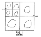
前述の米国特許は、寸法が可変のタイルを使用することを提案している。これは、通常オブジェクトはスクリーン全体に均等には分布しないという事実を反映している。本出願の図1に示すように、三つのタイル10は、三つのオブジェクトを収容できるよう一辺10ピクセルの正方形とされ、四つのタイル12は、四つのより小さいオブジェクトを収容できるよう一辺5ピクセルの正方形とされている。前述の特許において説明されているように、処理システムによって、いくつかのタイルについての画像の部分がパイプライン方式で処理される。
【0010】
我々は、前述のすべての特徴があるにもかかわらず処理能力がなお制約となり、しかしながら、本発明により処理能力を改善しうることを認識した。
【0011】
(発明の要約)
本発明の種々の態様が、特許請求の範囲に規定されており、ここでこれを参照することができる。特許請求の範囲には、本発明の好適な特徴が記載されている。
【0012】
以下に本発明の好適な実施例を、図面を参照しながらより詳細に説明する。簡単に述べると、本発明のこの好適な実施例は、画像をレンダリング(すなわち、カラーリング、テクスチャリング、あるいはシェーディング)するための画像処理装置という形態とされ、画像を分割して小領域又はタイルとするタイリングデバイスを含んでいる。二つのレンダリング・デバイスが設けられ、タイルは、いくつかが一つのレンダリング・デバイスによって、他のいくつかが別のレンダリング・デバイスによって処理されるように割り当てられる。表示しようとするオブジェクトの表面を表すポリゴンは、タイルと対照してテストされる。ある表面が一つの小領域だけに含まれる場合には、そのデータは一つのレンダリング・デバイスだけへ送られる。他方、ある表面が別々のレンダリング・デバイスによって処理される二つの小領域に含まれる場合には、そのデータは両方のレンダリング・デバイスへ送られる。結果として、データの実質的な部分だけを供給すればよく、これらは一つのレンダリング・デバイスによって処理されることになって、装置の動作速度が向上する。二つのレンダリング・デバイスの出力は、続いてタイルのインターリーブ動作及び画像表示回路によって結合される。
【0013】
以下では、図面を参照しながら、例示として本発明をより詳細に説明する。
【0014】
(好適な実施例の詳細な説明)
以下で、図2以降を参照しながら、画像処理、より詳しくは、3次元(3D)画像のリアルタイムでのテクスチャリングおよびシェーディングのための方法および装置について説明する。
【0015】
前述の導入部で説明した「バウンディング・ボリューム」技術は、完全にタイルの外側にあるバウンディング・ボリュームを有するオブジェクトはそのタイルについては破棄されるというものである。以下の説明では、この方針を実行する。すなわち、オブジェクトをスクリーンもしくは画像平面に投影し、この平面上において見えるバウンディング面をタイルと比較する。
【0016】
図2を参照する。同図には、12個の小領域すなわちタイル22を含むスクリーンの一部20が示されている。各タイルは、典型的には一辺が32ピクセル又は64ピクセルの正方形である。すなわち、従来のラスタ・スキャンを行うと、長さが32ピクセル又は64ピクセルで、高さが32ライン又は64ラインとなる。見て分かるように、この図には模式的に二つのオブジェクト、すなわち家24と自転車26が示されている。これらのオブジェクトは、例示のめに、二つのタイル22にわたるように延在させてある。これら二つのタイルは、家24の場合には像の上下に配置され、自転車の場合には横並びに配置されている。いずれの方法においても、オペレーションは同じである。
【0017】
これらのタイルは、二つのタイルグループに分割される。図に示したように、タイルは、市松模様状に二つのタイルグループに分割される。図2に示すように、タイルは一つ置きに明るく又は暗くシェーディングされ、各明るいタイル22Aは四つの暗いタイルによって囲まれ、各暗いタイル22Bは四つの明るいタイルによって囲まれる。明るいタイルと暗いタイルはそれぞれ、スクリーン全体について斜め模様を形成している。
【0018】
これまでは、オブジェクトのレンダリング、すなわちオブジェクトのテクスチャリング及びシェーディングを、単一のプロセッサによって処理したが、本発明では、これらを二つのプロセッサに分割する。これらのプロセッサをプロセッサA及びプロセッサBとする。各タイルグループを、これらのプロセッサA、プロセッサBのそれぞれと結びつける。すなわち、図2に示すように、明るいタイル22AはすべてプロセッサAに結びつけられ、暗いタイル22BはすべてプロセッサBに結びつけられる。明るいタイルの中に見える表面の処理はプロセッサAによって行われ、暗いタイルの中に見える表面の処理はプロセッサBによって行われる。
【0019】
複雑なオブジェクトは、一群のいくつかの小さなポリゴンによって構成されていることがわかる。たとえば家24は、屋根28のための三角形と、煙突30のための三角形及び四角形と、家の本体32、窓34、ドア36のための複数の長方形から構成されている。
【0020】
これらのうち屋根28と、煙突30と、二階の窓34の一つを形成するのポリゴンは、それぞれ全体が明るいタイル22Aの中に収まっており、したがってプロセッサA、すなわちデバイスAだけに送ればよい。ドア36と一階の窓34は、それぞれ全体が暗いタイル22Bの中に収まっており、したがってプロセッサB、すなわちデバイスBだけに送ればよい。しかしながら、家の本体32は、二つのタイルにまたがっている。したがって、これは明るいタイルと暗いタイルの両方における表示に影響を与えるので、両方のプロセッサ又はデバイスへ送る必要がある。
【0021】
自転車26についても同様に、前輪と前輪フォークとハンドルを構成するポリゴンはデバイスAだけに送られ、後輪と後輪フォークとサドルはデバイスBだけに送られるが、自転車のフレームについては両方のデバイスへ送られる。より大きなオブジェクトの場合は三つのタイル又はそれ以上にまたがって延在することもあるが、適用される処理及びその効果は、二つだけのタイルに重なるオブジェクトの場合と同じである。
【0022】
複雑のオブジェクトを構成するポリゴンの大きさは、そのポリゴン全体を囲むように四角形を描き、その四角形をスクリーンのタイルの座標と対照させてポリゴンの大きさを決定することによって得られる。これを、任意のポリゴン40を示した図3に例示する。このポリゴンは内側に凹んだものとして示されており、希望する場合は、便利なように内側に凹まない複数のポリゴンに細分することも可能であるが、バウンディングボックスを設定する方法は同じである。ポリゴンのデータは、ポリゴンの各頂点の座標値を与えることによって、レンダリング・デバイスへ供給される。この座標値は、X,Y,Zという三つの直交軸を有するデカルト座標系によって与えられる。最終的な表示スクリーンはX軸とY軸で形成される平面とされ、Z軸は、通常行われるように、オブジェクトの深度を表す。
バウンディングボックス42の角部44を規定するxとyの最小値の決定に用いる手順を、図4に示す。
【0023】
図4の手順50において、最初のステップ52では、最初に、処理される最初の頂点の入力値xin、yinが所望の値xmin、xmax、ymin、ymaxであると仮定する。続いてステップ54において次の頂点が処理される。新たな入力値xin、yinを、記憶されているxmin、xmax、ymin、ymaxと比較する。x又はyのいずれかについて、新たな入力値が記憶されている最小値よりも小さい場合は、新たな入力値で最小値を置き換え、新たな入力値が最大値を超える場合は、新たな入力値で最大値を置き換える。続いて手順はステップ56へ移行し、ここでポリゴンを規定する最後の頂点が処理されたかどうかをチェックする。ノーであれば、手順はステップ54へ戻って、次の頂点を処理する。一方、最後の頂点が処理された場合には、バウンディングボックス42の座標値がこれで決定され、手順はステップ58へ移行し、ここでバウンディングボックスがスクリーンの処理されているタイルと重なるかどうかの決定がなされる。この決定もまた、バウンディングボックス42の角部のXY座標値と、タイルの角部のXY座標値との単純な比較によって行われる。ピクセル数で表されるタイルの寸法は、例えば32又は64というような2のべき乗に選ぶのが望ましく、このようにすれば、スクリーンタイルテスト58は、多数の単純な二進数の比較に還元される。
【0024】
前述のバウンディングボックスの手法では、ごく希に、表面が実際には所与のタイル内に収まっていないときに、システムに収まっていると表示させる場合があるが、これは重大な問題にはならない。
【0025】
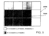
前述のように、タイルは、プロセッサA用とプロセッサB用という二つに、市松模様状に分割した。しかしながら、他の方法を用いてスクリーンを分割することもできる。最適な方法は画像内容に依存するであろうし、これにより一方のプロセッサが他方よりも多くのタイルを処理する場合もある。図5は分割形態を例示しており、ここでは大きい四角形2に、高さと幅の短い小さな四角形1が内包されている。プロセッサBは小さい四角形1を形成するタイルを処理するよう構成され、プロセッサAは残りのタイル、すなわち四角形2から四角形1を除いた部分のタイルを処理するよう構成されている。したがって、四角形1は、プロセッサAについて、インクルージョン四角形として定義され、四角形2はイクスクルージョン四角形として定義される。すなわち、全体が四角形1に含まれるすべてのポリゴンは、デバイスAに送られる。四角形1の外側、かつ四角形2の内側にあるポリゴンは、デバイスBへ送られる。二つの領域にまたがるポリゴンは、両方のデバイスへ送られる。
【0026】
スクリーンの分割は、相当数の表面がたった一つのプロセッサに送られるように行われる。すなわち、タイルは、表面のうちの相当の割合が一つのタイルだけに入る可能性が高くなるように、タイルのピクセルを単位とした一方の辺の長さが、もう一方の辺の例えばせいぜい2倍から3倍程度の四角形とするのが好ましい。このようにすると、たった一つのプロセッサへ送られる表面によって、処理は削減される。したがって、スキャンラインが一つ置きに異なるプロセッサによって処理されるように分割してしまうと、一本のスキャンラインに含まれる面の数というのはゼロ又はそれに近いことから、利点は得られない。他の可能な分割として、スクリーンを水平なバンドに分割する方法が考えられるが、この場合はバンド幅を十分に広く、例えばスクリーン全体を3分割又は4分割する程度にする必要があると考えられる。いずれの場合も、通常は少なくとも三つのスクリーン領域が存在し、プロセッサのうちの少なくとも一つが少なくとも二つの別々の離れた画像領域を処理するよう構成されるだろう。
【0027】
前述の実施例を実施化するのに必要なハードウエアは、図6に示すような形態のハードウェア構成をとる。図6は、本発明を具体化した画像処理装置60をブロック図として示したものであり、主メモリ64に接続された中央処理ユニット(CPU)62を備えている。タイル化デバイス66はタイルを定義し、CPU62との間だけでなくローカルメモリ68との間でも通信する。タイル化デバイスは、有効に二つの出力を有し、これらには第1のテクスチャリングもしくはレンダリング・デバイス70Aと、第2のテクスチャリングもしくはレンダリングデバイス70Bとに接続されている。二つのレンダリング・デバイス68A、68Bの出力は、いずれもタイル・インターリーブおよび画像表示回路72へ与えられている。好適なハードウエアのさらに詳しい説明については、我々の前述の米国特許を参照することができるが、重要なのは、タイル化デバイス66と回路72との間に、二つのレンダリングデバイス70A及び70Bが並列に接続されているという点である。
【0028】
実際には、タイル化デバイス66の二つの出力を、レンダリングデバイス70A、70Bのうち必要とされる一方を特定する適当なアドレス動作とともに、単一のデータバスとして構成することができる。
【0029】
図6の装置のオペレーションに含まれるステップは、おおむね以下のように説明することができる:
1. オブジェクトは、ユーザ(プログラマ)により生成される。これらは頂点と、そして各面に必要とされるテクスチャリングの種類を示すテクスチャ・コードによって定義される。これには色とその他の表面効果が含まれる。
2. バウンディングボックスは、前述の方法に従って、各面について生成される。
3. どの面がどのタイルに含まれるか、すなわち複数のレンダリングデバイス(ここでは二つ)のうちのどれがデータを必要としているかを決定するために、バウンディングボックスが、用いられているマクロなタイリング・パターンと対照して比較される。そして表面の頂点及びテクスチャ・コードが、各メモリデバイスに結びつけられた適切なローカル・メモリ部分に格納される。
4. この段階で、各レンダリング・デバイスに対するタイル表示リストが生成され、これにより、レンダリング・デバイスが動作するときには、そのタイルのそれぞれについてのデータを考慮するだけでよく、スクリーン表示リスト全体を考慮する必要はない。
5. タイルの各ピクセルについて、最も近い面が最初にリストされるよう、深度値にによって表面をソートする。
6. 前述の米国特許のレイ・キャスティング方法を用いて、その特定のピクセルにおいて見える最も前方にある不透明な面を見出す。
7. そして、このように最も前方に配置された目に見える面をレンダリングし、表面に希望する色、テクスチャ、シェーディングを与える。
8. この結果は、ディスプレイ・バッファに記憶される。
【0030】
本発明によれば、前述の各ステップのうちのいくつかは、並列に動作する二つのプロセッサにより実行される。このオペレーションは、前述の方法で、二つのプロセッサの間で割り当てられる。つまり、いくつかのタイル(上で明るいタイルとしたもの)についてのステップ7は一つのプロセッサによって実行され、他の(暗い)タイルについての同じステップは他方のプロセッサによって実行される。これによって処理に要する時間が、半分あるいはそれに近い程度に短縮される。二つのプロセッサの出力は結合されてディスプレー・バッファに供給され、続いてディスプレーのスクリーン上に表示される。
【0031】
したがって、このシステムは、例えば図2に示した家や自転車などのオブジェクトを表す一群の表面を定義するデータを与えることによって動作することが理解されるだろう。ディスプレイは、多数のタイルに分割され、どの面がどのタイルに入るかが決定される。そしてそのデータは、種々の表面がどのタイルに入っているかに応じて二つのレンダリング・デバイスに供給される。いくつかの表面のデータは一つのレンダリング・デバイスだけへ送られ、別の表面のデータは両方のレンダリング・デバイスへ送られるだろう。より詳しく言うと、例えば図2の屋根やドアのように、表面が一つのタイルだけに属しているときは、そのデータは一つのレンダリング・デバイスもしくはテクスチャリング・デバイスへ送られる。表面が、異なるレンダリング・デバイスによって処理される二つのタイルに属しているときは、その表面のデータは両方のレンダリング・デバイスへ送られる必要がある。
【0032】
表面が、同一のレンダリング・デバイスすなわち同一のプロセッサによって処理される二つのタイルにまたがる場合もあるが、そのような場合には、データは一つのレンダリング・デバイスのみへと送られればよい。これは図2のタイルの配置とは異なるが、別の構成では容易に起こりうるものである。
【0033】
例示した本発明の実施例では、通常は一つであるレンダリング用(例えばテクスチャリング又はシェーディング用)のプロセッサの代わりに二つのプロセッサが設けてあることを前提としている。しかしながら、本発明は、二つのデバイスの使用に限定されるものではなく、希望すれば二つよりも多く使用することもでき、その場合スクリーンは、それぞれのタイルグループを有する適切な多くの数の領域に分割される。
【0034】
例示した実施例は、プロセッサが同時並行的に動作し、各プロセッサは画像の全ての表面ではなくその幾分かだけを処理するばよいという事実から、通常の画像を処理すると仮定した場合に、処理時間が短縮されるという効果を有する。
【0035】
純粋に例示目的で説明し例示した上記のシステムに対しては、種々の変更を施すことが可能なことが理解されるだろう。
【図面の簡単な説明】
【図1】 米国特許第5,729,672号から引用した図であって、いくつかのオブジェクトを含み、可変サイズのタイルを有する画像平面の一部を例示している。
【図2】 本発明の実施の形態に基づいて、複数のタイルを含むスクリーンの一部を例示している。
【図3】 オブジェクトの周りのバウンディングボックスの図を示している。
【図4】 オブジェクトの周囲のバウンディングボックスの座標を決定するのに用いられる手順のフローチャートである。
【図5】 図1の実施例を変形した、タイルを含むスクリーンの一部を示した図である。
【図6】 本発明を実施化する好適な画像処理装置に使用するハードウエアの概略ブロック図である。[0001]
The present invention relates to an apparatus for processing an image.
[0002]
The invention can be suitably used in particular in systems for real-time-rendering, texturing or shading of three-dimensional (3D) images. However, it is not limited to this. Real-time here refers to displaying an image sufficiently quickly without causing a perceptible delay that can be perceived by the viewer.
[0003]
The existing best known system for generating real-time 3D images is the Z-buffer (or depth buffer) image accuracy algorithm. This Z-buffer algorithm requires a frame buffer in which the color value for each pixel (image element divided into elements) in the image is stored. In addition to this, a Z-buffer with an entrance for each pixel is required. This Z buffer stores the Z value or depth value for each pixel. To generate a 3D display, polygons are rendered in any order and placed into a frame buffer. When the following polygon is entered into the frame buffer, if the point on the polygon is closer to the viewer than the point already in the frame buffer for that pixel, the color of this new point and The Z value replaces the previously stored value. In the case of polygon texturing or shading, the polygon is textured or shaded before being rendered and put into the frame buffer. The system is given a list of vertices that define the polygons, and texturing and shading operations are performed for each polygon prior to performing the depth test. The performance of the system described above is limited by various factors such as input data bandwidth, texturing and shading speed, and local memory interface bandwidth. It has been proposed to use dual rendering devices to improve system performance, which is referred to as “scan line interleaving”. That is, two processors for alternately processing the scan lines of the image raster are provided, and the processing is shared between them.
[0004]
Another system for generating real-time 3D images is disclosed in US Pat. No. 5,729,672, assigned to Video Logic Limited. This system renders 3D images using “ray casting” technology rather than traditional polygon-based rendering. In this system, each object is represented by a set of surfaces stored as a data set. The image plane is between the viewer and the scene being viewed, and the image plane is composed of a plurality of pixels. Rays are assumed to reach the scene being seen through the screen pixels from the viewpoint, and intersect the various surfaces that represent the object in the scene. By analyzing these intersection points and the distance from the viewer, the system can determine whether the surface is visible. If the surface is visible, the surface is then textured or shaded as desired. However, if the surface is not visible, texturing or shading of the surface is not necessary. The advantage of this system over the Z buffer is that the invisible surface does not need to be textured or shaded.
[0005]
Image texturing or shading requires enormous processing capabilities. Thus, the reduction in processing achieved by the above-mentioned US patent system is extremely effective, especially for the types of images where many polygons or surfaces overlap each other.
[0006]
In the U.S. patent system described above, it is assumed that the surface defining the object extends across the entire image plane, i.e., is "infinite" in width. In addition, each surface is defined as a forward surface when it is in front of the object and facing the observer side, and when it faces the direction away from the observer by forming a part on the back side of the object Is defined as the reverse plane. In order to determine whether a given object is visible at a given pixel, ray casting techniques use: (a) the intersection of a ray farthest from this observation point with the forward plane; and (b) Compare each distance of the intersection of the reverse plane and the ray closest to the observation point. If (a) is greater than (b), this means that the ray does not intersect the object, as illustrated in the above patent, ie that particular object in the image plane through which the ray passes. Indicates that it cannot be seen. With this technique, the edge of the surface need not define or calculate itself, it is sufficient to know all the vertices of the object and calculate the plane that the surface occupies. It will be appreciated that this technique requires that all objects be checked for all pixels in the image plane to determine whether the object is visible at that location.
[0007]
As disclosed in the patent, this technique makes it very easy to shade the appropriate part of the image. The system can also handle transparency in various forms.
[0008]
Although this technique has advantages over the Z buffer system, processing requirements can still be a limitation. The patent proposes to improve performance by dividing the image plane or screen into a number of small areas or “tiles”. These tiles are rectangular (including squares) for convenience. And for each tile, the number of surfaces to be processed is reduced by first determining the objects that have faces that will fall within that tile and processing only the objects that are inside the tiles. . The determination of which objects contribute to each tile is made by surrounding the object with a bounding volume that completely contains the object, ie, a parallelepiped, and comparing the area of the tile with the bounding volume. To do this, all bounding volumes are projected onto the image plane and tested against the corners of the tile. Of these, objects with bounding faces that are completely outside of the tile are discarded for that tile. This reduces the total time to process all tiles, thus reducing the number of surfaces that must be processed per pixel in the tile and thus reducing the time to render the image.
[0009]
The aforementioned US patent proposes the use of tiles with variable dimensions. This reflects the fact that normally objects are not evenly distributed across the screen. As shown in FIG. 1 of the present application, the three
[0010]
We have recognized that despite all of the features described above, throughput is still a limitation, however, throughput can be improved with the present invention.
[0011]
(Summary of the Invention)
Various aspects of the invention are defined in the claims, to which reference can be made. The appended claims describe preferred features of the invention.
[0012]
Hereinafter, preferred embodiments of the present invention will be described in more detail with reference to the drawings. Briefly stated, this preferred embodiment of the present invention is in the form of an image processing device for rendering (ie, coloring, texturing, or shading) an image and dividing the image into small regions or tiles. Including tiling devices. Two rendering devices are provided, and tiles are assigned such that some are processed by one rendering device and some are processed by another rendering device. Polygons representing the surface of the object to be displayed are tested against the tiles. If a surface is contained in only one small area, the data is sent to only one rendering device. On the other hand, if a surface is contained in two small regions that are processed by separate rendering devices, the data is sent to both rendering devices. As a result, only a substantial portion of the data need be supplied and these will be processed by a single rendering device, increasing the operating speed of the apparatus. The outputs of the two rendering devices are then combined by tile interleaving and image display circuitry.
[0013]
In the following, the invention will be described in more detail by way of example with reference to the drawings.
[0014]
Detailed Description of the Preferred Embodiment
In the following, a method and apparatus for image processing, more specifically for real-time texturing and shading of a three-dimensional (3D) image will be described with reference to FIG.
[0015]
The “bounding volume” technique described in the introduction above is that an object with a bounding volume that is completely outside a tile is discarded for that tile. In the following description, this policy is implemented. That is, the object is projected onto a screen or image plane, and the bounding surface visible on this plane is compared with the tile.
[0016]
Please refer to FIG. In the figure, a
[0017]
These tiles are divided into two tile groups. As shown in the figure, the tile is divided into two tile groups in a checkered pattern. As shown in FIG. 2, every other tile is shaded light or dark, with each
[0018]
So far, the rendering of objects, i.e. object texturing and shading, has been processed by a single processor, but in the present invention these are divided into two processors. These processors are referred to as a processor A and a processor B. Each tile group is associated with each of these processors A and B. That is, as shown in FIG. 2, all
[0019]
It can be seen that a complex object is composed of a group of several small polygons. For example, the
[0020]
Of these, the polygons forming the roof 28, chimney 30 and one of the windows 34 on the second floor are all contained within the
[0021]
Similarly, for the
[0022]
The size of the polygon constituting the complex object is obtained by drawing a rectangle so as to surround the whole polygon and comparing the rectangle with the coordinates of the tiles on the screen to determine the size of the polygon. This is illustrated in FIG. 3 showing an
The procedure used to determine the minimum values of x and y that define the
[0023]
In the
[0024]
In the rare case of the bounding box approach described above, the surface may actually appear to be in the system when it is not within the given tile, but this is not a significant problem. .
[0025]
As described above, the tiles were divided into a checkered pattern into two for processor A and for processor B. However, the screen can be split using other methods. The optimal method will depend on the image content, so that one processor may process more tiles than the other. FIG. 5 exemplifies a division form. Here, a
[0026]
The screen splitting is done so that a significant number of surfaces are sent to only one processor. That is, the length of one side of a tile in units of tile pixels is, for example, at most 2 on the other side so that a significant proportion of the surface is likely to fall into only one tile. It is preferable to use a quadrilateral of about 3 to 3 times. In this way, processing is reduced by the surface being sent to only one processor. Therefore, if the scan lines are divided so that every other scan line is processed by a different processor, the number of planes included in one scan line is zero or close to it, and no advantage is obtained. Another possible division is to divide the screen into horizontal bands. In this case, the bandwidth should be sufficiently wide, for example, the entire screen needs to be divided into three or four. . In either case, there will typically be at least three screen areas, and at least one of the processors will be configured to process at least two separate image areas.
[0027]
The hardware necessary to implement the above-described embodiment has a hardware configuration as shown in FIG. FIG. 6 is a block diagram showing an
[0028]
In practice, the two outputs of the tiling device 66 can be configured as a single data bus, with appropriate addressing to identify one of the
[0029]
The steps involved in the operation of the apparatus of FIG. 6 can be described generally as follows:
1. The object is generated by a user (programmer). These are defined by vertices and texture codes that indicate the type of texturing required for each face. This includes color and other surface effects.
2. A bounding box is generated for each face according to the method described above.
3. To determine which face is included in which tile, ie which of the multiple rendering devices (here two) need the data, the bounding box is used for the macro tiling Compared against the pattern. The surface vertices and texture codes are then stored in the appropriate local memory portion associated with each memory device.
4). At this stage, a tiled display list for each rendering device is generated, so that when the rendering device operates, only the data for each of the tiles needs to be considered, and the entire screen display list need not be considered. Absent.
5). For each pixel in the tile, sort the surface by depth value so that the closest surface is listed first.
6). Using the ray casting method of the aforementioned U.S. patent, find the foremost opaque surface visible at that particular pixel.
7). Then, the visible surface arranged at the foremost position is rendered in this way, and the desired color, texture, and shading are given to the surface.
8). This result is stored in the display buffer.
[0030]
According to the present invention, some of the aforementioned steps are performed by two processors operating in parallel. This operation is allocated between the two processors in the manner described above. That is, step 7 for some tiles (light tiles above) is performed by one processor, and the same steps for other (dark) tiles are performed by the other processor. As a result, the time required for processing is reduced to half or close to it. The outputs of the two processors are combined and fed to the display buffer and subsequently displayed on the display screen.
[0031]
Thus, it will be appreciated that the system operates by providing data defining a group of surfaces representing objects such as the house and bicycle shown in FIG. The display is divided into a number of tiles and it is determined which face falls into which tile. The data is then fed to the two rendering devices depending on which tile the various surfaces are in. Some surface data will be sent to only one rendering device, and other surface data will be sent to both rendering devices. More specifically, when the surface belongs to only one tile, such as the roof or door of FIG. 2, the data is sent to one rendering device or texturing device. When a surface belongs to two tiles processed by different rendering devices, the data for that surface needs to be sent to both rendering devices.
[0032]
In some cases, the surface may span two tiles processed by the same rendering device, ie the same processor, in which case the data need only be sent to one rendering device. This is different from the tile arrangement of FIG. 2, but can easily occur in other configurations.
[0033]
In the illustrated embodiment of the present invention, it is assumed that two processors are provided in place of a single rendering (eg, texturing or shading) processor. However, the present invention is not limited to the use of two devices, but can be used more than two if desired, in which case the screen will have a suitable number of appropriate numbers with each tile group. Divided into regions.
[0034]
The illustrated embodiment assumes that the processor operates in parallel, and that each processor only processes some of the images rather than all the surfaces, and assumes that it is processing a normal image. The processing time is shortened.
[0035]
It will be understood that various modifications may be made to the system described and illustrated purely for exemplary purposes.
[Brief description of the drawings]
FIG. 1 is a drawing from US Pat. No. 5,729,672, illustrating a portion of an image plane containing several objects and having variable size tiles.
FIG. 2 illustrates a portion of a screen including a plurality of tiles according to an embodiment of the present invention.
FIG. 3 shows a diagram of a bounding box around an object.
FIG. 4 is a flowchart of a procedure used to determine the bounding box coordinates around an object.
FIG. 5 is a diagram showing a part of a screen including tiles, which is a modification of the embodiment of FIG. 1;
FIG. 6 is a schematic block diagram of hardware used in a preferred image processing apparatus embodying the present invention.
Claims (20)
画像内の各オブジェクトを表す一群の表面を定義するデータを供給する手段と、
ディスプレーを複数の小領域に分割する分割手段であって、前記供給手段に接続されているとともに、複数の出力を有する分割手段と、
それぞれが前記分割手段の複数の出力にそれぞれ接続された対応する複数のレンダリング・デバイスと、
前記複数のレンダリング・デバイスに接続され、表示のために前記複数のレンダリング・デバイスのそれぞれの出力を受け取り、かつ結合する結合手段とを含み、
前記分割手段は、
画像内容に基づいて前記小領域を小領域のグループに分割し、各グループを前記複数の出力の各一つ及び前記複数のレンダリング・デバイスのうちの対応するものに割り当てるよう構成されており、
得られたどの小領域にどの表面が入るかを決定するよう構成されており、そして
各小領域について該決定された表面のデータを前記複数の出力の各一つに適用する構成されており、
その表面が異なるレンダリング・デバイスによって処理される複数の小領域のうちの一つの小領域のみに入るか複数の処理領域に入るかに応じて、前記分割手段が、いくつかの表面のデータを一つのレンダリング・デバイスのみに送り、他の表面のデータを一つよりも多くのレンダリング・デバイスに送ることを特徴とする画像処理装置。An image processing apparatus comprising:
Means for supplying data defining a group of surfaces representing each object in the image;
A dividing means for dividing the display into a plurality of small regions, the dividing means being connected to the supply means and having a plurality of outputs ;
A corresponding plurality of rendering devices, each connected to a plurality of outputs of the dividing means;
Coupling means connected to the plurality of rendering devices for receiving and combining the output of each of the plurality of rendering devices for display;
The dividing means includes
Dividing the sub-regions into groups of sub-regions based on image content, each group being configured to assign to each one of the plurality of outputs and a corresponding one of the plurality of rendering devices;
Configured to determine which surface will fall into which sub-region obtained, and
Applying the determined surface data for each subregion to each one of the plurality of outputs;
Depending on whether the surface falls into a plurality of processing areas or entering to only one small area of the plurality of small regions that will be handled by different rendering devices, the dividing means, one some data of the surface An image processing apparatus that sends to only one rendering device and sends data for other surfaces to more than one rendering device.
Applications Claiming Priority (3)
| Application Number | Priority Date | Filing Date | Title |
|---|---|---|---|
| GB9824406A GB2343598B (en) | 1998-11-06 | 1998-11-06 | Image processing apparatus |
| GB9824406.4 | 1998-11-06 | ||
| PCT/GB1999/003716 WO2000028477A1 (en) | 1998-11-06 | 1999-11-08 | Image processing apparatus |
Publications (3)
| Publication Number | Publication Date |
|---|---|
| JP2002529865A JP2002529865A (en) | 2002-09-10 |
| JP2002529865A5 JP2002529865A5 (en) | 2007-01-11 |
| JP4480895B2 true JP4480895B2 (en) | 2010-06-16 |
Family
ID=10842011
Family Applications (1)
| Application Number | Title | Priority Date | Filing Date |
|---|---|---|---|
| JP2000581592A Expired - Lifetime JP4480895B2 (en) | 1998-11-06 | 1999-11-08 | Image processing device |
Country Status (7)
| Country | Link |
|---|---|
| US (1) | US6750867B1 (en) |
| EP (1) | EP1125250B1 (en) |
| JP (1) | JP4480895B2 (en) |
| AT (1) | ATE258327T1 (en) |
| DE (1) | DE69914355T2 (en) |
| GB (1) | GB2343598B (en) |
| WO (1) | WO2000028477A1 (en) |
Families Citing this family (28)
| Publication number | Priority date | Publication date | Assignee | Title |
|---|---|---|---|---|
| EP1412922A1 (en) * | 2000-12-22 | 2004-04-28 | Volume Interactions Pte. Ltd. | A method of rendering a graphics image |
| US7061495B1 (en) * | 2002-11-18 | 2006-06-13 | Ati Technologies, Inc. | Method and apparatus for rasterizer interpolation |
| US7796133B1 (en) | 2002-11-18 | 2010-09-14 | Ati Technologies Ulc | Unified shader |
| US8933945B2 (en) * | 2002-11-27 | 2015-01-13 | Ati Technologies Ulc | Dividing work among multiple graphics pipelines using a super-tiling technique |
| US7633506B1 (en) * | 2002-11-27 | 2009-12-15 | Ati Technologies Ulc | Parallel pipeline graphics system |
| JP2005100176A (en) * | 2003-09-25 | 2005-04-14 | Sony Corp | Image processor and its method |
| US8133115B2 (en) | 2003-10-22 | 2012-03-13 | Sony Computer Entertainment America Llc | System and method for recording and displaying a graphical path in a video game |
| US7403661B2 (en) * | 2004-02-12 | 2008-07-22 | Xerox Corporation | Systems and methods for generating high compression image data files having multiple foreground planes |
| US20060071933A1 (en) | 2004-10-06 | 2006-04-06 | Sony Computer Entertainment Inc. | Application binary interface for multi-pass shaders |
| ATE383627T1 (en) * | 2004-11-19 | 2008-01-15 | Ericsson Telefon Ab L M | METHOD AND DEVICE FOR GENERATING THREE-DIMENSIONAL IMAGES |
| US7636126B2 (en) | 2005-06-22 | 2009-12-22 | Sony Computer Entertainment Inc. | Delay matching in audio/video systems |
| US7965859B2 (en) | 2006-05-04 | 2011-06-21 | Sony Computer Entertainment Inc. | Lighting control of a user environment via a display device |
| US7880746B2 (en) | 2006-05-04 | 2011-02-01 | Sony Computer Entertainment Inc. | Bandwidth management through lighting control of a user environment via a display device |
| GB2449398B (en) * | 2006-09-29 | 2009-02-11 | Imagination Tech Ltd | Improvements in memory management for systems for generating 3-dimensional computer images |
| US8797320B2 (en) * | 2007-08-02 | 2014-08-05 | Disney Enterprises, Inc. | Surface shading of computer-generated object using multiple surfaces |
| GB2452731B (en) * | 2007-09-12 | 2010-01-13 | Imagination Tech Ltd | Methods and systems for generating 3-dimensional computer images |
| GB0723536D0 (en) | 2007-11-30 | 2008-01-09 | Imagination Tech Ltd | Multi-core geometry processing in a tile based rendering system |
| JP5120174B2 (en) * | 2008-09-18 | 2013-01-16 | 富士通株式会社 | Drawing device |
| US8152613B2 (en) * | 2009-01-14 | 2012-04-10 | Sony Computer Entertainment America Llc | Tiled objects in digital environments |
| GB0922126D0 (en) | 2009-12-17 | 2010-02-03 | Advanced Risc Mach Ltd | Graphics processing systems |
| JP5393574B2 (en) | 2010-04-08 | 2014-01-22 | キヤノン株式会社 | Image processing apparatus, image processing method, and program |
| US10786736B2 (en) | 2010-05-11 | 2020-09-29 | Sony Interactive Entertainment LLC | Placement of user information in a game space |
| JP5595151B2 (en) | 2010-07-13 | 2014-09-24 | キヤノン株式会社 | Image processing apparatus, compression method in image processing apparatus, and program |
| JP5643574B2 (en) * | 2010-08-26 | 2014-12-17 | キヤノン株式会社 | Image processing apparatus and image processing method |
| JP5664052B2 (en) | 2010-09-15 | 2015-02-04 | 富士通セミコンダクター株式会社 | Graphic processing apparatus and graphic processing program |
| US9342817B2 (en) | 2011-07-07 | 2016-05-17 | Sony Interactive Entertainment LLC | Auto-creating groups for sharing photos |
| GB2494903B (en) | 2011-09-22 | 2017-12-27 | Advanced Risc Mach Ltd | Graphics processing systems |
| EP2648107B1 (en) * | 2012-04-05 | 2016-09-28 | Siemens Healthcare GmbH | Volume rendering on shared memory systems with multiple processors by optimizing cache reuse |
Family Cites Families (4)
| Publication number | Priority date | Publication date | Assignee | Title |
|---|---|---|---|---|
| GB8828342D0 (en) * | 1988-12-05 | 1989-01-05 | Rediffusion Simulation Ltd | Image generator |
| US5008838A (en) * | 1989-11-17 | 1991-04-16 | Digital Corporation | Method for simultaneous initialization of a double buffer and a frame buffer |
| US5729672A (en) * | 1993-07-30 | 1998-03-17 | Videologic Limited | Ray tracing method and apparatus for projecting rays through an object represented by a set of infinite surfaces |
| US6313841B1 (en) * | 1998-04-13 | 2001-11-06 | Terarecon, Inc. | Parallel volume rendering system with a resampling module for parallel and perspective projections |
-
1998
- 1998-11-06 GB GB9824406A patent/GB2343598B/en not_active Expired - Lifetime
-
1999
- 1999-11-08 DE DE69914355T patent/DE69914355T2/en not_active Expired - Lifetime
- 1999-11-08 US US09/831,386 patent/US6750867B1/en not_active Expired - Lifetime
- 1999-11-08 JP JP2000581592A patent/JP4480895B2/en not_active Expired - Lifetime
- 1999-11-08 AT AT99954179T patent/ATE258327T1/en not_active IP Right Cessation
- 1999-11-08 EP EP19990954179 patent/EP1125250B1/en not_active Revoked
- 1999-11-08 WO PCT/GB1999/003716 patent/WO2000028477A1/en active IP Right Grant
Also Published As
| Publication number | Publication date |
|---|---|
| EP1125250A1 (en) | 2001-08-22 |
| GB9824406D0 (en) | 1998-12-30 |
| DE69914355T2 (en) | 2004-11-11 |
| US6750867B1 (en) | 2004-06-15 |
| EP1125250B1 (en) | 2004-01-21 |
| GB2343598A (en) | 2000-05-10 |
| JP2002529865A (en) | 2002-09-10 |
| ATE258327T1 (en) | 2004-02-15 |
| GB2343598B (en) | 2003-03-19 |
| WO2000028477A1 (en) | 2000-05-18 |
| DE69914355D1 (en) | 2004-02-26 |
Similar Documents
| Publication | Publication Date | Title |
|---|---|---|
| JP4480895B2 (en) | Image processing device | |
| US6636212B1 (en) | Method and apparatus for determining visibility of groups of pixels | |
| US7145565B2 (en) | Depth bounds testing | |
| JP4237271B2 (en) | Method and apparatus for attribute interpolation in 3D graphics | |
| US5596685A (en) | Ray tracing method and apparatus for projecting rays through an object represented by a set of infinite surfaces | |
| US7126600B1 (en) | Method and apparatus for high speed block mode triangle rendering | |
| US6774910B2 (en) | Method and system for providing implicit edge antialiasing | |
| US20030006983A1 (en) | Graphics processor, system and method for generating screen pixels in raster order utilizing a single interpolator | |
| US6919906B2 (en) | Discontinuity edge overdraw | |
| JP2001357410A (en) | Graphic system for composing three-dimensional images generated separately | |
| US20170221255A1 (en) | Image processing apparatus and method | |
| US11250620B2 (en) | Graphics processing | |
| US20110227921A1 (en) | Processing of 3D computer graphics data on multiple shading engines | |
| JP4499291B2 (en) | Shading and texturing 3D computer generated images | |
| US5265198A (en) | Method and processor for drawing `polygon with edge`-type primitives in a computer graphics display system | |
| US7116333B1 (en) | Data retrieval method and system | |
| US6839058B1 (en) | Depth sorting for use in 3-dimensional computer shading and texturing systems | |
| Yu | Efficient visibility processing for projective texture mapping | |
| KR20230032826A (en) | Method for merging layer based on virtual z-thickness in multi-fragment rendering, apparatus and computer program for performing the method | |
| JPH09319892A (en) | Image processor and its processing method | |
| EP0725365A1 (en) | Shading three-dimensional images | |
| CN1501326A (en) | 3D digital image processor and visibility processing method used thereon | |
| KR0180160B1 (en) | Rendering method of 3-dimensional material | |
| US7414635B1 (en) | Optimized primitive filler |
Legal Events
| Date | Code | Title | Description |
|---|---|---|---|
| A521 | Request for written amendment filed |
Free format text: JAPANESE INTERMEDIATE CODE: A523 Effective date: 20061106 |
|
| A621 | Written request for application examination |
Free format text: JAPANESE INTERMEDIATE CODE: A621 Effective date: 20061106 |
|
| A131 | Notification of reasons for refusal |
Free format text: JAPANESE INTERMEDIATE CODE: A131 Effective date: 20090721 |
|
| A601 | Written request for extension of time |
Free format text: JAPANESE INTERMEDIATE CODE: A601 Effective date: 20091020 |
|
| A602 | Written permission of extension of time |
Free format text: JAPANESE INTERMEDIATE CODE: A602 Effective date: 20091027 |
|
| A521 | Request for written amendment filed |
Free format text: JAPANESE INTERMEDIATE CODE: A523 Effective date: 20100121 |
|
| TRDD | Decision of grant or rejection written | ||
| A01 | Written decision to grant a patent or to grant a registration (utility model) |
Free format text: JAPANESE INTERMEDIATE CODE: A01 Effective date: 20100218 |
|
| A01 | Written decision to grant a patent or to grant a registration (utility model) |
Free format text: JAPANESE INTERMEDIATE CODE: A01 |
|
| A61 | First payment of annual fees (during grant procedure) |
Free format text: JAPANESE INTERMEDIATE CODE: A61 Effective date: 20100317 |
|
| FPAY | Renewal fee payment (event date is renewal date of database) |
Free format text: PAYMENT UNTIL: 20130326 Year of fee payment: 3 |
|
| R150 | Certificate of patent or registration of utility model |
Ref document number: 4480895 Country of ref document: JP Free format text: JAPANESE INTERMEDIATE CODE: R150 Free format text: JAPANESE INTERMEDIATE CODE: R150 |
|
| FPAY | Renewal fee payment (event date is renewal date of database) |
Free format text: PAYMENT UNTIL: 20130326 Year of fee payment: 3 |
|
| FPAY | Renewal fee payment (event date is renewal date of database) |
Free format text: PAYMENT UNTIL: 20140326 Year of fee payment: 4 |
|
| R250 | Receipt of annual fees |
Free format text: JAPANESE INTERMEDIATE CODE: R250 |
|
| R250 | Receipt of annual fees |
Free format text: JAPANESE INTERMEDIATE CODE: R250 |
|
| R250 | Receipt of annual fees |
Free format text: JAPANESE INTERMEDIATE CODE: R250 |
|
| R250 | Receipt of annual fees |
Free format text: JAPANESE INTERMEDIATE CODE: R250 |
|
| R250 | Receipt of annual fees |
Free format text: JAPANESE INTERMEDIATE CODE: R250 |
|
| R250 | Receipt of annual fees |
Free format text: JAPANESE INTERMEDIATE CODE: R250 |
|
| R250 | Receipt of annual fees |
Free format text: JAPANESE INTERMEDIATE CODE: R250 |
|
| EXPY | Cancellation because of completion of term |