JP4478956B2 - Anti-theft case - Google Patents
Anti-theft case Download PDFInfo
- Publication number
- JP4478956B2 JP4478956B2 JP2006144144A JP2006144144A JP4478956B2 JP 4478956 B2 JP4478956 B2 JP 4478956B2 JP 2006144144 A JP2006144144 A JP 2006144144A JP 2006144144 A JP2006144144 A JP 2006144144A JP 4478956 B2 JP4478956 B2 JP 4478956B2
- Authority
- JP
- Japan
- Prior art keywords
- case
- slider
- theft
- sliders
- guide
- Prior art date
- Legal status (The legal status is an assumption and is not a legal conclusion. Google has not performed a legal analysis and makes no representation as to the accuracy of the status listed.)
- Active
Links
Images


Landscapes
- Packaging For Recording Disks (AREA)
- Packaging Of Annular Or Rod-Shaped Articles, Wearing Apparel, Cassettes, Or The Like (AREA)
- Closures For Containers (AREA)
Description
この発明は、CDカセットの音楽や映像を記録してあるディスクやビデオテープ、ゲームソフト、その他の商品(収納ケースに商品を収納した状態のもの)の盗難を防止するケースに関する。 The present invention relates to a case for preventing theft of discs, video tapes, game software, and other products (in a state where products are stored in a storage case) in which music and videos in a CD cassette are recorded.
レンタルショップ陳列棚に上述のような商品を収納ケースを並べておくと、顧客による収納ケースの開放が可能なため、レンタルショップ側の盗難防止ケースに収納ケースを嵌め込んで陳列することで、顧客による収納ケースの開放ができなくなって、商品が盗難に遭うのを防止する。 If storage cases are arranged on the rental shop display shelf, the storage case can be opened by the customer, so the storage case is inserted into the anti-theft case on the rental shop side and displayed by the customer. Prevents the product from being stolen when the storage case cannot be opened.
レンタルに際しては、レンタルショップのカウンタに盗難防止ケースを持参することで、ショップ側の解除具により施錠が解除されて、盗難防止ケースから収納ケースを取り出すことができ、取り出した収納ケースを貸し出す(特許文献1)。 When renting, bring the anti-theft case to the counter of the rental shop, the lock is released by the release tool on the shop side, the storage case can be taken out from the anti-theft case, and the taken out storage case is lent out (patent Reference 1).
なお、販売に際しても同様の方式が採用される。
ところで、特許文献1の構造によると、解除具のキーを貫通孔に挿入して押し込むと、キーの先端がスライダのテーパー面部に当り、キーの押し込み続行により弾片による押し戻し力に抗してスライダを押し逃がして貫通孔の縁から掛止爪が外れて、この外れにともなう係合関係の解除により昇降体と共に突出部材の降下ができてケース本体内の商品の押し上げがなくなって、ケース本体内からの商品の取り出しが可能になる。
By the way, according to the structure of
しかしながら、各貫通孔にそれぞれのキーの先端を合致させたのち、この合致を維持しながら各貫通孔にそれぞれのキーを一度に押し込んで各貫通孔の縁と掛止爪との係合関係を解除するため、貫通孔に対するキーの合致に手数がかかると共に、各キーの均一な同時押し込みができないと、先行するキーと、若干遅れるキーとで各キーのスムーズな押し込みができない問題があった。 However, after aligning the tip of each key with each through-hole, the key is pushed into each through-hole at the same time while maintaining this match, and the engagement relationship between the edge of each through-hole and the latching claw is established. In order to cancel, there is a problem in that matching of the key to the through-hole is troublesome, and if each key cannot be pushed in at the same time, each key cannot be pushed smoothly by the preceding key and the key slightly delayed.
特に、係合関係の解除をケース本体毎行なうので、一度に複数のケース本体の掛合関係を解除することができない。 In particular, since the engagement relationship is released for each case body, the engagement relationship of a plurality of case bodies cannot be released at a time.
そこで、この発明は、上述の問題を解消した盗難防止ケースを提供することにある。 Therefore, the present invention is to provide a theft prevention case that solves the above-mentioned problems.
上記の課題を解決するために、請求項1の発明は、周側面の1つの壁に商品の丈よりも短かくて上記商品の出し入れ用の開口を有するケース本体と、このケース本体の頂壁に上面を開放させて設けたガイドと、このガイドの底壁から突出する係止爪と、このガイドの底壁に前記ケース本体の開口側の辺縁に設けた貫通する長孔と、この長孔にストッパ片を貫通させて上記ガイド内に昇降自在に嵌入した昇降体と、このストッパ片の両側縁突出方向端に設けた抜止め用の突部と、上記昇降体内に上記長孔に沿ってスライドするように組み込んだスライダと、このスライダに設けた鉄片と、このスライダに一方向の押圧力を付与するバネと、上記スライダに上記昇降体の押し込みにともない前記係止爪に当接してスライダを押し逃がし、かつ上記昇降体の押し込み終了にともない上記押し逃がしが解放されて上記係止爪に係合するように設けた係止部とで構成される盗難防止ケースと、上記盗難防止ケースに当接させた時、上記鉄片を磁力により引き寄せて、スライダの係止部とガイドの係止爪の係合を解除可能とした永久磁石を有する解除具とからなる盗難防止装置において、前記スライダとバネとはそれぞれ左右一対とし、かつ、バネは両スライダを接近方向への押圧力を付与しており、前記解除具には、盗難防止ケースの昇降体付近に当接させた際、両スライダの鉄片外側に位置して両スライダを離反方向に引き寄せるように永久磁石が2つ設けてある構成を採用する。In order to solve the above-mentioned problems, the invention of
また、請求項2の発明は、上記請求項1に記載の盗難防止装置に用いる解除具であって、基材と、この基材に一端側に位置決め壁を有し、かつ複数の並列する盗難防止ケースを上方から嵌入するように設けた凹入部と、この凹入部の底の両端側で盗難防止ケースの両スライダの鉄片外側に位置して上記両鉄片を磁吸により引き寄せるように設けた永久磁石とからなる解除具を使用する。The invention of
すると、係合関係の解除を極めてスムーズに行なうことができ、一度に複数のケース本体の係合関係の解除もできる。 Then, the engagement relationship can be released very smoothly, and the engagement relationship between a plurality of case bodies can be released at once.
以上のように、この発明の盗難防止ケースによれば、ガイドの底に昇降体を押し込むことで、係止爪に係止部が当接して押圧力に抗して両スライダを押し逃がし、係止部が係止爪を通過し終ると押し逃がしの解除された両スライダを押し戻しながら、係止爪と係止部とが係合関係になって、昇降体と一体のストッパ片により開口の一部を閉鎖する。 As described above, according to the anti-theft case of the present invention, by pushing the elevating body into the bottom of the guide, the locking portion comes into contact with the locking claw and pushes both sliders against the pressing force. When the stop portion has passed through the locking claw, the locking claw and the locking portion are engaged with each other while pushing back both of the released sliders. Close the part.
このため、ケース本体内の商品の抜き取りを阻止して盗難防止に効果を発揮する。 For this reason, the removal of the product in the case main body is prevented, and the effect is exhibited for theft prevention.
また、解除具の凹入部に昇降体を先行させてケース本体を嵌め込むと共に、位置決め壁により嵌め込んだケース本体の正確な位置決めを行なうことで、両スライダの鉄片が凹入部の底の両端の並列永久磁石により磁吸しながら両スライダを強制的に離反方向に強制にスライドさせながら、係止爪と係止部との係合関係を解除し、この状況下で凹入部から上方にケース本体を引き抜くことで、脱出方向に昇降体を永久磁石と鉄片との磁吸により強制的にスライドさせる。 In addition, the case body is fitted with the lifting body preceding the recessed portion of the release tool, and the case body fitted by the positioning wall is accurately positioned, so that the iron pieces of both sliders are located at both ends of the bottom of the recessed portion. While the magnetic force is absorbed by the parallel permanent magnets, both the sliders are forcibly slid in the separating direction, and the engagement relationship between the locking claw and the locking portion is released. By pulling out, the lifting body is forcibly slid in the escape direction by magnetic absorption between the permanent magnet and the iron piece.
このため、ストッパ片による開口の一部の閉鎖がなくなって、ケース本体から商品の取り出しが(ショップ側による)可能になる。 For this reason, part of the opening of the stopper piece is not closed, and the product can be taken out from the case body (by the shop side).
さらに、凹入部に複数のケース本体を嵌め込むことができるので、一度に複数のケース本体の係合関係の解除が可能になる。 Furthermore, since a plurality of case main bodies can be fitted into the recessed portions, the engagement relationship between the plurality of case main bodies can be released at a time.
以下、この発明の実施の形態を添付図面に基づいて説明する。 Embodiments of the present invention will be described below with reference to the accompanying drawings.
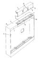
この発明の第1の実施形態では、図1から図5に示すように、ケース本体Aの周側面の一つの壁1には、商品Bの丈よりも短かくて商品Bを出し入れする開口2が設けてある。
In the first embodiment of the present invention, as shown in FIGS. 1 to 5, an
上記開口2の丈を商品Bの丈よりも短かくする要因は、開口2の下縁からケース本体A内に商品Bの下縁側を先行させて嵌入したのち、商品Bの上縁を開口2の上縁の下を通過させて嵌め込む。
The reason for making the length of the
その際、開口2の下縁(壁1の内側)の内側に商品Bの下縁部が納まって、開口2に対する商品Bのすべり出しを阻止することにある。
At that time, the lower edge portion of the product B is accommodated inside the lower edge of the opening 2 (inside the wall 1), thereby preventing the product B from sliding out of the
又ケース本体Aの頂壁3に上面を開放させた筒状のガイド4を設けると共に、ガイド4の底壁5の開口2に合致する線上に上下面が貫通する長孔6を設けておく。
In addition, a
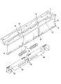
更に、ガイド4に昇降体7を昇降自在に嵌入すると共に、この昇降体7に長孔6に貫通するストッパ片8を設け、ストッパ片8の両側縁の突出方向端には、ストッパ片8の下縁(突出方向縁)と開口2の上縁とが合致するように昇降体7を脱出方向にスライドさせたとき、底壁5の下面に当接してストッパ片8が上方に抜けるのを防止する突部9が設けてある。
Further, the
又昇降体7内の両端側に長孔6に沿ってスライドするスライダ10を組み込むと共に、このスライダ10に接近方向に強制スライドさせる押圧力の付与バネ11が組み込んである。
In addition, a
上記のスライダ10は、図示の場合、昇降体7内に長孔6に平行する上面開放のガイド溝12を設けて、このガイド溝12にスライド自在に嵌め込んでガイドし、バネ11は、図示の場合、スライダ10の対向内端壁13と昇降体7から突出する受座片14とにバネ11の両端を支持させてある。
In the illustrated case, the
更にガイド4内の底壁5から上方に向けて両スライダ10、10の対向端間に納まる銛状の係止爪15を設け、両スライダ10、10の対向端には、昇降体7の押し込みにともない係止爪15の山形テーパー面部に当接してスライダ10を押し逃がし、昇降体7の押し込み終了にともない山形テーパー面部から外れて係止爪15に係合関係になる係止部16が設けてある。
Further, a hook-
又両スライダ10、10には、解除具Cの永久磁石34によって両スライダ10、10をバネ11による押圧力に抗して離反方向に強制スライドさせるための磁吸用鉄片21が設けてある。
Both
なお、係止爪15は、図示の場合両スライダ10、10の両端側にも(底壁5から突出させて)設けて、この係止爪15に両スライダ10、10の相反する端縁に係止部16を設けたが、限定されず、昇降体7の中間部のみ或いは中間部と両端の両方に設けるなど選択すればよい。
In the illustrated case, the
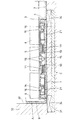
上記の解除具Cは、図6、7に示すように、基材31と、この基材31に一端側に位置決め壁32を有し、かつ複数の並列する盗難防止ケース本体Aを上方から嵌入するように設けた凹入部33と、この凹入部33の底面下側で、両鉄片21の端の外側に位置して鉄片21を磁吸する永久磁石34とで構成されている。
As shown in FIGS. 6 and 7, the release tool C has a
なお、商品Bとしては、例えば収納ケースにディスクを収納したものである。 In addition, as the product B, for example, a disc is stored in a storage case.
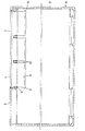
上記のように構成すると、開口2からケース本体A内に商品Bを嵌め込んだのち、昇降体7を押し下げる。
If comprised as mentioned above, after fitting the goods B in the case main body A from the
押し下げにともない係止爪15に係止部16が当接すると、係止爪15と係止部16とのテーパー面部により両スライダ10を離反方向に押し逃がし、係止部16が係止爪15を通過し終ると、バネ11によって両スライダ10を接近方向にスライドさせて、図4に示すように係止爪15と係止部16とが係合関係になって昇降体7の押し状態の維持をはかる。
When the
このとき、昇降体7と共にストッパ片8を共に押し下げて、ストッパ片8により開口2の一部(図示上縁側)を閉鎖するので、ケース本体Aからの商品Bの抜き取りが阻止され、盗難防止になる。
At this time, the
なお、ショップからのケース本体Aの持ち出しは、周知のように、ケース本体Aに設けた盗難防止タグ(図示省略)により検出する。 In addition, taking out of the case main body A from a shop is detected by the antitheft tag (illustration omitted) provided in the case main body A as is well known.
次にショップ側で商品Bを取り出す(販売やレンタルのため)場合、解除具Cの凹入部33に単数並列する複数のケース本体Aを図7に示すように昇降体7を下側にして上方から嵌入する。
Next, when taking out the product B at the shop side (for sale or rental), a plurality of case bodies A arranged in parallel with the
このとき、位置決め壁32にケース本体Aの壁を当接する。
At this time, the wall of the case body A is brought into contact with the
すると、両側の永久磁石34、34によって鉄片21を磁吸して、相反する方向にスライダ10、10をスライドさせて、図6に示すように、係止爪15と係止部16との係合関係を解除する。
Then, the
この状況下にケース本体Aを上方に抜き去ると、永久磁石34によって鉄片21を磁吸しているので、ケース本体Aを抜き去る際、凹入部33の底に図8に示すように昇降体7がとどまって、ガイド4内から昇降体7が脱出方向にスライドして、ストッパ片8により開口2の一部閉鎖をなくすると共に、図9に示すように突部9が長孔6の端に引っかかって、解除具Cからケース本体Aを抜き去ることができる。
When the case main body A is removed upward in this situation, the
このため、ショップ側でケース本体Aから商品Bを取り出すことができる。 For this reason, the product B can be taken out from the case main body A on the shop side.
図中61は、ガイド手段である。 In the figure, 61 is guide means.
A ケース本体
B 商品
C 解除具
1 壁
2 開口
3 頂壁
4 ガイド
5 底壁
6 長孔
7 昇降体
8 ストッパ片
9 突部
10 スライダ
11 バネ
12 ガイド溝
13 内端壁
14 受座片
15 係止爪
16 係止部
21 鉄片
31 基材
32 位置決め壁
33 凹入部
34 永久磁石
A Case body B Product
Claims (2)
Priority Applications (1)
| Application Number | Priority Date | Filing Date | Title |
|---|---|---|---|
| JP2006144144A JP4478956B2 (en) | 2006-05-24 | 2006-05-24 | Anti-theft case |
Applications Claiming Priority (1)
| Application Number | Priority Date | Filing Date | Title |
|---|---|---|---|
| JP2006144144A JP4478956B2 (en) | 2006-05-24 | 2006-05-24 | Anti-theft case |
Publications (2)
| Publication Number | Publication Date |
|---|---|
| JP2007314201A JP2007314201A (en) | 2007-12-06 |
| JP4478956B2 true JP4478956B2 (en) | 2010-06-09 |
Family
ID=38848439
Family Applications (1)
| Application Number | Title | Priority Date | Filing Date |
|---|---|---|---|
| JP2006144144A Active JP4478956B2 (en) | 2006-05-24 | 2006-05-24 | Anti-theft case |
Country Status (1)
| Country | Link |
|---|---|
| JP (1) | JP4478956B2 (en) |
Citations (5)
| Publication number | Priority date | Publication date | Assignee | Title |
|---|---|---|---|---|
| JPH0530921U (en) * | 1991-09-19 | 1993-04-23 | 船井電機株式会社 | Small electronic device lid |
| JPH09202377A (en) * | 1996-01-29 | 1997-08-05 | Sanei:Kk | Retainer for software containing case |
| JP2002125817A (en) * | 2000-10-24 | 2002-05-08 | Just Corporation:Kk | Display case for cd or the like with antitheft function and unlocking device |
| JP2003155058A (en) * | 2001-09-05 | 2003-05-27 | Nisshin:Kk | Case |
| JP2006123935A (en) * | 2004-10-27 | 2006-05-18 | Sanei:Kk | Opening and closing locking apparatus and its unlocking apparatus for commodity displaying case |
-
2006
- 2006-05-24 JP JP2006144144A patent/JP4478956B2/en active Active
Patent Citations (5)
| Publication number | Priority date | Publication date | Assignee | Title |
|---|---|---|---|---|
| JPH0530921U (en) * | 1991-09-19 | 1993-04-23 | 船井電機株式会社 | Small electronic device lid |
| JPH09202377A (en) * | 1996-01-29 | 1997-08-05 | Sanei:Kk | Retainer for software containing case |
| JP2002125817A (en) * | 2000-10-24 | 2002-05-08 | Just Corporation:Kk | Display case for cd or the like with antitheft function and unlocking device |
| JP2003155058A (en) * | 2001-09-05 | 2003-05-27 | Nisshin:Kk | Case |
| JP2006123935A (en) * | 2004-10-27 | 2006-05-18 | Sanei:Kk | Opening and closing locking apparatus and its unlocking apparatus for commodity displaying case |
Also Published As
| Publication number | Publication date |
|---|---|
| JP2007314201A (en) | 2007-12-06 |
Similar Documents
| Publication | Publication Date | Title |
|---|---|---|
| US6601415B2 (en) | Disk container provided with antitheft function and unlocking tool | |
| KR100400874B1 (en) | Anti-theft container | |
| US6155087A (en) | Reduced-encumbrance anti-theft case, particularly for compact disks, musicassettes videocassettes and the like | |
| JP4616866B2 (en) | Product display case opening and closing locking device and unlocking device | |
| JP4478956B2 (en) | Anti-theft case | |
| ITTO20000598A1 (en) | CONTAINER FOR THE DISPLAY OF ITEMS WITH PROTECTION AGAINST THEFT. | |
| JP2009073558A (en) | Antitheft device | |
| JP3994348B2 (en) | Rental cases such as DVDs with anti-theft function and unlocking tools | |
| JP2010047292A (en) | Releasing device for anti-theft case | |
| JP3994349B2 (en) | Rental cases such as DVDs with anti-theft function and unlocking tools | |
| JP2010047291A (en) | Anti-theft case and releasing device | |
| JP2004345736A (en) | Anti-theft device | |
| JP3978686B2 (en) | Rental cases such as DVDs with anti-theft function and unlocking tools | |
| JP2009298474A (en) | Case | |
| JP4119050B2 (en) | Case holder | |
| KR100541714B1 (en) | Security Device for information storage media | |
| JP2004345736A5 (en) | ||
| JP2006323428A (en) | Antitheft method for displayed book, and device therefor | |
| JP3545741B2 (en) | Case | |
| JP2006188235A (en) | Theft preventive apparatus | |
| JP2000191078A (en) | Case | |
| JP2007030931A (en) | Anti-theft arrangement | |
| KR20070006290A (en) | Case locking apparatus for preventing robbery | |
| JP3370028B2 (en) | Anti-theft case | |
| JP2928490B2 (en) | Rental system and anti-theft case |
Legal Events
| Date | Code | Title | Description |
|---|---|---|---|
| A711 | Notification of change in applicant |
Free format text: JAPANESE INTERMEDIATE CODE: A711 Effective date: 20080910 |
|
| A521 | Written amendment |
Free format text: JAPANESE INTERMEDIATE CODE: A821 Effective date: 20080910 |
|
| A871 | Explanation of circumstances concerning accelerated examination |
Free format text: JAPANESE INTERMEDIATE CODE: A871 Effective date: 20081031 |
|
| A521 | Written amendment |
Free format text: JAPANESE INTERMEDIATE CODE: A821 Effective date: 20081008 |
|
| A521 | Written amendment |
Free format text: JAPANESE INTERMEDIATE CODE: A821 Effective date: 20081027 |
|
| A521 | Written amendment |
Free format text: JAPANESE INTERMEDIATE CODE: A523 Effective date: 20090807 |
|
| A521 | Written amendment |
Free format text: JAPANESE INTERMEDIATE CODE: A821 Effective date: 20090807 |
|
| A975 | Report on accelerated examination |
Free format text: JAPANESE INTERMEDIATE CODE: A971005 Effective date: 20090914 |
|
| A131 | Notification of reasons for refusal |
Free format text: JAPANESE INTERMEDIATE CODE: A131 Effective date: 20090929 |
|
| RD04 | Notification of resignation of power of attorney |
Free format text: JAPANESE INTERMEDIATE CODE: A7424 Effective date: 20091019 |
|
| A521 | Written amendment |
Free format text: JAPANESE INTERMEDIATE CODE: A523 Effective date: 20091127 |
|
| TRDD | Decision of grant or rejection written | ||
| A01 | Written decision to grant a patent or to grant a registration (utility model) |
Free format text: JAPANESE INTERMEDIATE CODE: A01 Effective date: 20100302 |
|
| A01 | Written decision to grant a patent or to grant a registration (utility model) |
Free format text: JAPANESE INTERMEDIATE CODE: A01 |
|
| A61 | First payment of annual fees (during grant procedure) |
Free format text: JAPANESE INTERMEDIATE CODE: A61 Effective date: 20100304 |
|
| FPAY | Renewal fee payment (event date is renewal date of database) |
Free format text: PAYMENT UNTIL: 20130326 Year of fee payment: 3 |
|
| R150 | Certificate of patent or registration of utility model |
Free format text: JAPANESE INTERMEDIATE CODE: R150 |
|
| FPAY | Renewal fee payment (event date is renewal date of database) |
Free format text: PAYMENT UNTIL: 20130326 Year of fee payment: 3 |
|
| RVTR | Cancellation of determination of trial for invalidation | ||
| FPAY | Renewal fee payment (event date is renewal date of database) |
Free format text: PAYMENT UNTIL: 20130326 Year of fee payment: 3 |