JP4478444B2 - Central architecture for remote service delivery - Google Patents
Central architecture for remote service delivery Download PDFInfo
- Publication number
- JP4478444B2 JP4478444B2 JP2003421875A JP2003421875A JP4478444B2 JP 4478444 B2 JP4478444 B2 JP 4478444B2 JP 2003421875 A JP2003421875 A JP 2003421875A JP 2003421875 A JP2003421875 A JP 2003421875A JP 4478444 B2 JP4478444 B2 JP 4478444B2
- Authority
- JP
- Japan
- Prior art keywords
- data
- operation data
- central
- monitor
- operational
- Prior art date
- Legal status (The legal status is an assumption and is not a legal conclusion. Google has not performed a legal analysis and makes no representation as to the accuracy of the status listed.)
- Expired - Fee Related
Links
Images


Classifications
-
- G—PHYSICS
- G07—CHECKING-DEVICES
- G07C—TIME OR ATTENDANCE REGISTERS; REGISTERING OR INDICATING THE WORKING OF MACHINES; GENERATING RANDOM NUMBERS; VOTING OR LOTTERY APPARATUS; ARRANGEMENTS, SYSTEMS OR APPARATUS FOR CHECKING NOT PROVIDED FOR ELSEWHERE
- G07C5/00—Registering or indicating the working of vehicles
- G07C5/008—Registering or indicating the working of vehicles communicating information to a remotely located station
-
- G—PHYSICS
- G07—CHECKING-DEVICES
- G07C—TIME OR ATTENDANCE REGISTERS; REGISTERING OR INDICATING THE WORKING OF MACHINES; GENERATING RANDOM NUMBERS; VOTING OR LOTTERY APPARATUS; ARRANGEMENTS, SYSTEMS OR APPARATUS FOR CHECKING NOT PROVIDED FOR ELSEWHERE
- G07C5/00—Registering or indicating the working of vehicles
- G07C5/08—Registering or indicating performance data other than driving, working, idle, or waiting time, with or without registering driving, working, idle or waiting time
-
- H—ELECTRICITY
- H04—ELECTRIC COMMUNICATION TECHNIQUE
- H04Q—SELECTING
- H04Q9/00—Arrangements in telecontrol or telemetry systems for selectively calling a substation from a main station, in which substation desired apparatus is selected for applying a control signal thereto or for obtaining measured values therefrom
-
- Y—GENERAL TAGGING OF NEW TECHNOLOGICAL DEVELOPMENTS; GENERAL TAGGING OF CROSS-SECTIONAL TECHNOLOGIES SPANNING OVER SEVERAL SECTIONS OF THE IPC; TECHNICAL SUBJECTS COVERED BY FORMER USPC CROSS-REFERENCE ART COLLECTIONS [XRACs] AND DIGESTS
- Y10—TECHNICAL SUBJECTS COVERED BY FORMER USPC
- Y10S—TECHNICAL SUBJECTS COVERED BY FORMER USPC CROSS-REFERENCE ART COLLECTIONS [XRACs] AND DIGESTS
- Y10S707/00—Data processing: database and file management or data structures
- Y10S707/99931—Database or file accessing
- Y10S707/99937—Sorting
Landscapes
- Physics & Mathematics (AREA)
- General Physics & Mathematics (AREA)
- Engineering & Computer Science (AREA)
- Computer Networks & Wireless Communication (AREA)
- Testing And Monitoring For Control Systems (AREA)
- Selective Calling Equipment (AREA)
- Management, Administration, Business Operations System, And Electronic Commerce (AREA)
Description
本発明は、一般的に、遠隔で機器を監視すると共に診断情報、予測情報、及びその他の情報を機器に提供するシステムアーキテクチャに関する。 The present invention relates generally to a system architecture that remotely monitors a device and provides diagnostic information, predictive information, and other information to the device.
ガスタービン、ジェットエンジン、産業用モータ、機関車などの重工業用機器の性能は時の経過と共に低下し、最終的には故障を起こす。機器の性能が許容し難いレベルにまで低下し、機器のユーザがこのレベルの低下に気づいた場合、ユーザは機器サービスプロバイダに電話をかけ、ユーザと機器サービスプロバイダとの間のサービス契約に従って必要な保守又は修理を行なうよう依頼するであろう。また、サービスプロバイダは、機器のユーザからの電話がない場合でも、契約に従って機器の保守を定期的に実施するであろう。
本発明の一面によると、遠隔地側機器に関する運転データを収集する少なくとも1台の遠隔地側機器モニタと通信を行なうための中央側システムが提供される。中央側システムは、前記少なくとも1台の遠隔地側機器モニタから前記運転データを受信するように構成されるデータ転送システムと、前記データ転送システムから前記運転データを受信し、そのデータ記憶装置に前記運転データを格納する運転データアクセスシステムと、前記運転データに基づくデータを受信し、所定のスケジュールに従って宛先へと配信する通知分散システムとを具備する。 According to one aspect of the present invention, a central system is provided for communicating with at least one remote device monitor that collects operational data relating to a remote device. The central system receives a data transfer system configured to receive the operation data from the at least one remote device monitor, receives the operation data from the data transfer system, and stores the operation data in the data storage device. An operation data access system that stores operation data, and a notification distribution system that receives data based on the operation data and distributes the data to a destination according to a predetermined schedule.
本発明の別の面によると、遠隔地側機器に関する運転データを収集する少なくとも1台の遠隔地側機器モニタと通信を行なうための中央側システムが提供される。中央側システムは、前記少なくとも1台の遠隔地側機器モニタから前記運転データを受信するように構成されるデータ転送システムと、前記データ転送システムから前記運転データを受信し、そのデータ記憶装置に前記運転データを格納する運転データアクセスシステムと、前記運転データアクセスシステムと通信を行なって運転データを受信し、前記受信した運転データの分析に基づいて前記少なくとも1台の機器モニタにより監視される機器の動作状態の表示を提供する診断エンジンとを具備する。 In accordance with another aspect of the present invention, a central system is provided for communicating with at least one remote device monitor that collects operational data regarding the remote device. The central system receives a data transfer system configured to receive the operation data from the at least one remote device monitor, receives the operation data from the data transfer system, and stores the operation data in the data storage device. An operation data access system for storing operation data; and an operation data access system that communicates with the operation data access system to receive operation data and that is monitored by the at least one device monitor based on an analysis of the received operation data. And a diagnostic engine that provides an indication of the operating state.
本発明の現在好適な実施例について詳細に言及する。同様の要素に言及する場合には、図面全体を通して可能な限り同じ符号を用いるものとする。 Reference will now be made in detail to the presently preferred embodiments of the invention. Wherever possible, the same reference numbers will be used throughout the drawings to refer to the same elements.
本発明者は、機器側で機器運転データを収集し、その運転データを機器側から遠く離れた中央側に転送し、機器に関する診断を実施することが可能なシステムアーキテクチャに対する要望があることを認識してきた。このシステムアーキテクチャを使用する機器サービスプロバイダは、運転データを管理することで幾つかの利点を得ると共に改良した機器を提供することができる。例えば、サービスプロバイダは、機器の健全性又は状態に関する中央側が保存しているデータの集合に基づいて十分に情報を得た状態で、遠隔の機器を修理、交換、又は保守するためのサービスコールをかける時機及びかけることの是非について決定を下すことができるであろう。 The inventor recognizes that there is a need for a system architecture that can collect device operation data on the device side, transfer the operation data to a central side far from the device side, and perform diagnosis on the device. I have done it. Equipment service providers using this system architecture can gain operational benefits and provide improved equipment by managing operational data. For example, a service provider may make a service call to repair, replace, or maintain a remote device with sufficient information based on a collection of data stored by the central party regarding the health or status of the device. You will be able to make decisions about when and when to call.
更に、遠隔の機器に関係があり、サービスプロバイダ及びユーザにとって重要なその他の情報を中央側で相互に関係づけて適切な宛先へと配信することができる。たとえば、機器に関する保証データが中央側で利用可能である場合、この保証データの支援により、サービスプロバイダは機器の現在の監視状態に基づいて十分情報を得た状態で、いかなるアクションをとるべきかについて決定を下すことになる。排出規制などの規制を受ける機器に関しては、機器の排出物及び規制についてのデータを中央側で保存することもできる。この場合、機器が排出基準を満たしていないことをサービスプロバイダ又はユーザに通知し、適切なアクションをとることができる。 In addition, other information that is related to the remote device and is important to the service provider and the user can be correlated to the central side and distributed to the appropriate destination. For example, if warranty data about a device is available on the central side, with the assistance of this warranty data, what actions should the service provider take with sufficient information based on the current monitoring status of the device? Make a decision. For devices that are subject to regulations such as emission regulations, data on the emissions and regulations of the equipment can be stored on the central side. In this case, the service provider or user can be notified that the device does not meet the emission criteria, and appropriate action can be taken.
中央側でのデータ保管及び診断と遠隔地側での運転データ収集とを統合することにより提供される情報インフラは、柔軟な対処が可能である。この統合システムは、機器運転データへのアクセス、機器の構成情報へのアクセス、運転データの変換及び配信、機器の故障などのイベントの通知、レポート及びメッセージの生成、及び視覚化、診断、及びその他の用途向けのウェブベース且つユーザベースの各ツールの統合の各機能を提供するであろう。 The information infrastructure provided by integrating data storage and diagnosis on the central side and operational data collection on the remote side can be handled flexibly. This integrated system provides access to device operational data, access to device configuration information, conversion and distribution of operational data, notification of events such as device failures, report and message generation, and visualization, diagnosis, and others Will provide web-based and user-based tool integration capabilities for different applications.
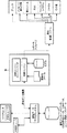
図1は、本発明の好適な実施例に係る中央側システム10の概略図である。中央側システム10は遠隔地側機器モニタ11と通信を行なう。中央側システム10は破線内に示されている。遠隔地側機器モニタ11は本実施例では中央側システム10の一部ではなく、中央側システム10から遠く離れている。遠隔地側機器モニタ11は、ガスタービン、ジェットエンジンなどの1台以上の機器(不図示)を機器側で監視し、機器に関する運転データを収集する。遠隔地側機器モニタ11は、監視対象の機器と直接に又は機器のコントローラ(不図示)とインタフェースする。遠隔地側機器モニタ11は運転データを自動的に回収・保存しても良い。運転データとは、機器の速度及び温度並びに場合によっては排出データなどの機器の運転に関するデータである。機器モニタは従来技術において一般的に知られている。
FIG. 1 is a schematic diagram of a
中央側システム10はデータ転送システム18を含む。データ転送システム18は、遠隔地側機器モニタ11から運転データを受信するように構成される。一般的に、データ転送システム18は複数の遠隔地側機器モニタ、少なくとも1台の遠隔地側機器モニタに接続されることになる。また、データ転送システム18は、遠隔地側機器モニタ11から受信した運転データを運転データアクセスシステム12へと転送する。
The
中央側システム10は、図1に示すような他の複数のサブシステムも含む。これらのサブシステムは、運転データアクセスシステム12に運転データを要求して受信し、データをカスタマイズして少なくとも1つのカスタムデータセットへと変換する運転データ配信システム20と、運転データアクセスシステム12に運転データを要求して受信し、運転データを少なくとも1つの所定の情報レポートへと変換する運転データ報告システム22と、運転データアクセスシステム12に運転データを要求して受信し、所定の変換定義に従って運転データを変換データへと変換する運転データ変換システム24とを含む。
The
中央側システム10は、運転データに基づくデータを受信し、それを所定のスケジュールに従って宛先へと配信する通知配信システム26を更に含む。通知配信システム26は、データ転送システム18、運転データ配信システム20、運転データ報告システム22、及び運転データ変換システム24のうちのいずれかからデータを受信しても良い。通知配信システム26は、様々な宛先と通信するための複数の通信モード30を含む。通信モードは、プリンタ30a、メッセージ待ち行列30b、電子メール30c、ファクシミリ30d、ページングシステム30e、データ格納ファイル30f、及びその他の通信モード30gを含んでも良い。通信モードは、プリンタなどの中央側システム10の外部の各通信装置(不図示)に接続される。
The
中央側システム10は、システムとユーザの対話を可能にするワークセンタ14も含む。ワークセンタ14は、ユーザに対してデータをグラフィカルに及び/又は数値的に表示するビューワ15を含んでも良い。ビューワ15は、例えば、監視・診断ビューワ(M&Dビューワ)であっても良い。あるいは、ビューワ15はワークセンタ14から独立していても良い。
The
中央側システム10の各サブシステムを以下で詳細に説明する。
Each subsystem of the
図2は、データ転送システム18を示すと共に、他のサブシステム及び遠隔地側機器モニタ11との通信を示す。説明の便宜上、図2には全てのサブシステムは示されていない。データ転送システム18は、遠隔地側機器モニタ11から中央側システム10への運転データ転送のスケジューリング、遠隔地側機器モニタ11と中央側システム10との間での通信の開始、及びデータ転送及びファイル転送の管理を担当する。
FIG. 2 shows the
データ転送システム18は、データ転送部40及びデータ転送マネージャ42を含む。データ転送部40は、遠隔地側機器モニタ11との接続を開始するように構成される。また、データ転送部40は、運転データアクセスシステム12とインタフェース・通信して運転データベースへのデータ挿入を要求すると共に、通知配信システム26にインタフェースして新規のデータメッセージ、すなわち、新規の運転データを遠隔地側機器モニタ11から受信したというメッセージを提供する。
The
データ転送マネージャ42は、データ転送スケジュールに従った遠隔地側機器モニタ11からの運転データの転送を行なう。データ転送マネージャ42は、転送スケジュールを管理するために独自のデータベースシステムを含んでも良い。転送スケジュールは、例えば、運転データ要素のリスト、サンプルの転送速度、データ転送の間隔、次のデータ転送時間、及びその他の関連データを含んでも良い。データ転送マネージャ42は転送のスケジューリングを担当する。
The
図3は、運転データ配信システム20及び他のサブシステムとの通信を示す。説明の便宜上、図3には全てのサブシステムは示されていない。運転データ配信システム20は、カスタムデータセットの管理を担当する。これらのデータセットは、例えば、ローカルなデータベースサーバ上に配置することが可能なデータマートに格納されても、あるいは、複数のデータベースサーバに配信されても良い。
FIG. 3 shows communication with the operation
運転データ配信システム20は、運転データアクセスシステム12に運転データを要求して受信し、データをカスタマイズして少なくとも1つのカスタムデータセットへと変換する。運転データ配信マネージャ20は、カスタムデータセット配信のスケジューリングを担当する。このシステムは、運転データアクセスシステム12とインタフェースし、運転データを要求すると共にデータを適切なデータマートへと挿入する。運転データ配信システム20は、運転データ配信スケジュールに従って少なくとも1つのカスタムデータセットを通知配信システム26へと転送する。通知配信システム26は、運転データ配信スケジュールに従ってその少なくとも1つのカスタムデータセットを適切な宛先へと転送する。
The driving
運転データ配信システム20は、カスタムデータセットの抽出及び配信を管理するのに独自のデータベースシステムを使用しても良い。例えば、カスタムデータセットは、ガスタービン機器の振動を監視するためのセンサを含む機器モニタ11を備える機器側に対するものとすることもできる。このデータセットは、通知配信システム26を介してワークステーション又はエンジニアの適切な宛先へと配信することができる。
The operating
図4は、運転データ報告システム22及び他のサブシステムとの通信を示す。説明の便宜上、図4には全てのサブシステムが示されていない。運転データ報告システム22は、規定のスケジュールに従って運転データを所定の情報レポートへと変換する。これらのレポートはグラフィカルな情報のみならずテキスト情報も含むことができる。運転データ報告システム22は、データベースシステムにおけるレポート定義及びレポートスケジュールを管理する。運転データ報告マネージャ22は、どのレポートをいつ処理すべきかを判定する。運転データ報告マネージャ22は、運転データアクセスシステム12にインタフェースしてデータを要求し、レポートメッセージを伴って通知配信システム26に通知する。
FIG. 4 illustrates communication with the operational
運転データ報告システム22は、運転データアクセスシステム12に運転データを要求して受信し、運転データを少なくとも1つの所定の情報レポートへと変換する。運転データ報告システム22は、情報レポート配信スケジュールに従って少なくとも1つの所定の情報レポートを通知配信システム26へと転送する。通知配信システム26は、所定の情報レポート配信スケジュールに従って少なくとも1つの所定の情報レポートを適切な宛先へと転送する。
The driving
図5は、運転データ変換システム24及び他のサブシステムとの通信を示す。説明の便宜上、図5には全てのサブシステムは示されていない。運転データ変換システム24は、運転データをより有用な形式へと変換する。データ変換とは、ある種のアルゴリズムをデータに適用することを示す。例えば、ハイパスフィルタリング、ローパスフィルタリング、及び重み付け平均化などをデータに適用しても良い。運転データ変換システム24は、データについての計算を実行し、結果のセットを生成することもできる。このシステムは、変換のスケジューリングのためのマネージャと、変換定義及び変換スケジュールを格納するためのローカルなデータベースとを有する。運転データ変換システム24は、運転データアクセスシステム12と通信し、データの検索・格納を行なう。変換の終了の際には、配信のために通知配信システム26にメッセージが送信されても良い。
FIG. 5 shows communication with the operation
運転データ変換システム24は、運転データアクセスシステム12に運転データを要求して受信し、所定の変換定義に従って運転データを変換データへと変換する。運転データ変換システム24は、変換データ配信スケジュールに従って変換データを通知配信システム26へと転送する。通知配信システム26は、変換データ配信スケジュールに従って変換データを適切な宛先へと転送する。
The operation
図6は、通知配信システム26及び他のサブシステムとの通信を示す。通知配信システム26は、情報を配信するためにあらゆるサービスに対して利用可能な汎用サービスを提供する。通知配信システム26は、プリンタ30a用のモード、メッセージ待ち行列30b用のモード、電子メール30c用のモード、FAX30d用のモード、ページングシステム30e用のモード、ファイル30f用のモード、及びその他30g用のモードを含む複数の通信モード30に対応する。通知配信システム26は、スケジューリング管理及び情報配信のためのマネージャと、配信規則を格納するためのデータ記憶装置とを有する。通知配信システム26のマネージャは、規則の作成、修正、及び削除のためのユーザインタフェースを提供しても良い。通信は非同期通信にすることも、同期通信にすることもできる。
FIG. 6 shows communication with the
図7は、診断エンジン16及び他のサブシステムとの通信を示す。説明の便宜上、図7には全てのサブシステムは示されていない。診断エンジン16は、運転データアクセスシステム12と通信を行なって運転データを受信し、受信した運転データの分析に基づいて少なくとも1台の機器モニタにより監視される機器の運転状態の表示を提供する。運転状態の表示は、例えば、機器の故障又は機器の性能の低下であっても良い。
FIG. 7 illustrates communication with the
診断エンジン16は、運転データを処理するアプリケーション、異常を判定又は識別するアプリケーション、及び予測及び結果を生成するアプリケーションを含む。診断エンジン16は、通常、運転データに適用される際に監視対象の機器の健全性を予測するルールベース又はモデルベースのアルゴリズムを含む。モデル又はアルゴリズム及び知識ベースを初期化するための初期化ファイルは、診断エンジン16のデータベースに含まれても良い。初期化情報は診断機器内の運転データと共に使用されても良い。システムユーザが適切な運転データが分析で使用されることを要求して診断エンジンを起動しても良いし、あるいは、これが自動的に実施されても良い。診断エンジン16は、運転データアクセスシステム12とインタフェースしてデータ検索挿入を実行し、警報及びその他のレポート形式のメッセージを伴って通知分散システム26と通信する。
The
図1に戻って、運転データアクセスシステム12、ワークセンタ14、及びビューワ15を詳細に説明する。運転データアクセスシステム12は、ワークセンタ14を介して運転データアクセスシステム12の中央側データ記憶装置13への安全で透過的なアクセスを提供しても良い。また、運転データアクセスシステム12は、各クライアントアプリケーションに対する共通のインタフェースを提供すると共に、ワークセンタ14を介して複数のデータ収集戦略及び複数のデータ削減戦略に対応しても良い。
Returning to FIG. 1, the operation
ワークセンタ14は、ウェブブラウザと、中央側10の機能及び活動を支援する一群の協調アプリケーションのホストとして機能する統合ソフトウェアとを含んでも良い。ワークセンタ14は、複数のユーザアプリケーションのうちのいずれか1つを介する運転データアクセスシステムとユーザの会話を可能にする。ワークセンタ14は、アプリケーション間の情報の共有を促進する。すなわち、生産性及びサービス配信の効率を向上させる。アプリケーションには、例えば、機器健全性監視、電子ノート、機器診断、機器問題エスカレーション、機器予測、及びレコード及びジャーナルの管理が含まれる。また、ワークセンタ14は、各管理アプリケーションのホストとして機能しても良く、管理アプリケーションは、機器及び人員の監視のスケジューリング、作業負荷バランシング、及びサービス契約遵守を含んでも良い。管理アプリケーションは、時間管理及びセッション管理を支援できるものであっても良い。
The
ビューワ15は、データをグラフィカル且つ数値的に表示し、プロット及びデータセットの定義を可能にすると共に、運転データアクセスシステム12とインタフェースしてデータを検索する。ユーザは、要求された結果セットのデータ量を削減するためのフィルタを指定することができる。プロットは、各レポートに含めるべく種々の形式へとエクスポートすることができる。
The
図8は、ワークセンタ14において想定されるユーザのシナリオを示す。ユーザはワークセンタ14にログオンすることにより開始する。その後、ユーザは所望のアプリケーションを選択しても良い。このシナリオでは、ユーザはまず健全性評価アプリケーションを実行し、遠隔で監視される機器の健全性を評価することを選択する。ユーザは健全性評価アプリケーションをクリックしてアプリケーションを開始し、割り当てられた機器識別子を入力する。ユーザは、機器のうちの識別された1台の健全性に関する情報をディスプレイ上で見るであろう。ユーザはこの健全性評価を確認する。
FIG. 8 shows a user scenario assumed in the
ユーザは、別のアプリケーションを実行することを選択しても良い。この場合、別のユニットを選択し、診断結果アプリケーションをクリックしてアプリケーションを開始する。ユーザは、先に識別された1台の機器に対する診断結果をディスプレイ上で評価し、例えば、電子ノートアプリケーションにコメント及び所見を保存することができる。ユーザは、次に、所見の推移を見るために呼出し追跡アプリケーションを起動することを選択しても良い。ユーザは、必要に応じて、ワークセンタ14から複数のアプリケーションの使用を継続することができる。
The user may choose to run another application. In this case, another unit is selected and the diagnostic result application is clicked to start the application. The user can evaluate the diagnosis result for one previously identified device on the display, and can store comments and findings in an electronic notebook application, for example. The user may then choose to launch a call tracking application to see the changes in findings. The user can continue to use a plurality of applications from the
本発明を特定の実施例に関して詳細に説明したが、本発明の趣旨から逸脱することなく、変形及び変更を行なっても良いことは当業者には明らかであろう。特許請求の範囲に記載された符号は、理解容易のためであってなんら発明の技術的範囲を実施例に限縮するものではない。 Although the invention has been described in detail with respect to particular embodiments, it will be apparent to those skilled in the art that changes and modifications may be made without departing from the spirit of the invention. The reference signs in the claims are for easy understanding and do not limit the technical scope of the invention to the embodiments.
10…中央側システム、11…遠隔地側機器モニタ、12…運転データアクセスシステム、13…中央側データ記憶装置、16…診断エンジン、18…データ転送システム、26…通知分散システム
DESCRIPTION OF
Claims (8)
前記少なくとも1台の遠隔地側機器モニタ(11)から前記運転データを受信するように構成されるデータ転送システム(18)と、
前記データ転送システム(18)から前記運転データを受信し、そのデータ記憶装置(13)に前記運転データを格納する運転データアクセスシステム(12)と、
前記運転データに基づくデータを受信し、宛先へと配信する通知分散システム(26)と、
前記運転データアクセスシステム(12)と通信を行なって運転データを受信し、運転データを処理するアプリケーション、異常を判定又は識別するアプリケーション、及び予測及び結果を生成するアプリケーションを使用することにより、前記受信した運転データの分析に基づいて前記少なくとも1台の機器モニタ(11)により監視される機器の異常の予測及び結果に関する動作状態の表示を提供する診断エンジン(16)と、
を具備し、
診断を繰り返し実行して、前記監視される機器の所見の推移を継続して見るための呼出し追跡アプリケーションがユーザにより選択的に起動可能に構成され、前記呼出し追跡アプリケーションの使用が継続される、中央側システム(10)。 In a central system (10) for communicating with at least one remote device monitor (11) that collects operational data about the remote device.
A data transfer system (18) configured to receive the operating data from the at least one remote device monitor (11);
An operation data access system (12) for receiving the operation data from the data transfer system (18) and storing the operation data in the data storage device (13);
A notification distribution system (26) that receives data based on the operation data and distributes the data to a destination;
Receiving by using the application that communicates with the driving data access system (12) to receive the driving data, processes the driving data, determines or identifies anomalies, and generates the predictions and results A diagnostic engine (16) that provides an indication of an operational condition related to a prediction and result of an abnormality of the equipment monitored by the at least one equipment monitor (11) based on an analysis of the operational data performed;
Comprising
Repeatedly executes diagnostics, the call tracking application for viewing by continuing trends findings of equipment to be monitored is selectively activatable configured by the user, it is Ru is continued use of the call tracking application, the central Side system (10).
The central data storage device (13) of the operation data access system (12) stores, in addition to the operation data, other data related to equipment monitored by the at least one remote site monitor (11). Item 1. The central system (10) according to item 1.
Applications Claiming Priority (1)
| Application Number | Priority Date | Filing Date | Title |
|---|---|---|---|
| US10/248,157 US7184844B2 (en) | 2002-12-20 | 2002-12-20 | Central site architecture for remote service delivery |
Publications (3)
| Publication Number | Publication Date |
|---|---|
| JP2004206713A JP2004206713A (en) | 2004-07-22 |
| JP2004206713A5 JP2004206713A5 (en) | 2007-02-08 |
| JP4478444B2 true JP4478444B2 (en) | 2010-06-09 |
Family
ID=32392320
Family Applications (1)
| Application Number | Title | Priority Date | Filing Date |
|---|---|---|---|
| JP2003421875A Expired - Fee Related JP4478444B2 (en) | 2002-12-20 | 2003-12-19 | Central architecture for remote service delivery |
Country Status (3)
| Country | Link |
|---|---|
| US (1) | US7184844B2 (en) |
| EP (1) | EP1432273A3 (en) |
| JP (1) | JP4478444B2 (en) |
Families Citing this family (21)
| Publication number | Priority date | Publication date | Assignee | Title |
|---|---|---|---|---|
| JP2002300308A (en) * | 2001-03-30 | 2002-10-11 | Ricoh Co Ltd | Customer support system, office system, customer support center, supply center and customer support method |
| US7184844B2 (en) * | 2002-12-20 | 2007-02-27 | General Electric Company | Central site architecture for remote service delivery |
| JP4692774B2 (en) * | 2004-09-14 | 2011-06-01 | 日本電気株式会社 | Data distribution system and data distribution method |
| CN100458858C (en) * | 2006-03-30 | 2009-02-04 | 纬创资通股份有限公司 | Remote monitoring method with active alarm ability |
| CN101627629B (en) * | 2007-03-08 | 2014-01-01 | 汤姆森特许公司 | Method, apparatus and system for coordinated content distribution workflow |
| US20090089247A1 (en) * | 2007-09-28 | 2009-04-02 | Terrence Lynn Blevins | Methods and apparatus to standardize data properties in a process control environment |
| US9306877B2 (en) * | 2008-10-09 | 2016-04-05 | Thomas And Sons, Inc. | Notification system |
| US8886746B2 (en) * | 2009-09-09 | 2014-11-11 | Rockwell Automation Technologies, Inc. | Diagnostic module for distributed industrial network including industrial control devices |
| KR101866270B1 (en) * | 2011-02-21 | 2018-07-05 | 삼성전자주식회사 | Data sharing system and method thereof |
| CN104481702A (en) * | 2014-10-15 | 2015-04-01 | 哈尔滨东安发动机(集团)有限公司 | A monitoring method of micro gas turbine operation states |
| US10218630B2 (en) | 2014-10-30 | 2019-02-26 | Pearson Education, Inc. | System and method for increasing data transmission rates through a content distribution network |
| US10116563B1 (en) | 2014-10-30 | 2018-10-30 | Pearson Education, Inc. | System and method for automatically updating data packet metadata |
| US10735402B1 (en) | 2014-10-30 | 2020-08-04 | Pearson Education, Inc. | Systems and method for automated data packet selection and delivery |
| US10318499B2 (en) | 2014-10-30 | 2019-06-11 | Pearson Education, Inc. | Content database generation |
| US10027740B2 (en) * | 2014-10-31 | 2018-07-17 | Pearson Education, Inc. | System and method for increasing data transmission rates through a content distribution network with customized aggregations |
| US10333857B1 (en) | 2014-10-30 | 2019-06-25 | Pearson Education, Inc. | Systems and methods for data packet metadata stabilization |
| US10110486B1 (en) | 2014-10-30 | 2018-10-23 | Pearson Education, Inc. | Automatic determination of initial content difficulty |
| CN104574219A (en) * | 2015-01-28 | 2015-04-29 | 华东电网有限公司 | System and method for monitoring and early warning of operation conditions of power grid service information system |
| EP3449413A1 (en) * | 2016-04-25 | 2019-03-06 | Intertrust Technologies Corporation | Data management systems and methods |
| CN106354118B (en) * | 2016-08-25 | 2019-08-09 | 株洲中车时代电气股份有限公司 | A kind of train fault diagnostic system and method based on fault tree |
| JP7460233B2 (en) * | 2018-09-28 | 2024-04-02 | 日本電気株式会社 | Information processing device, information processing method, program, and data structure |
Family Cites Families (25)
| Publication number | Priority date | Publication date | Assignee | Title |
|---|---|---|---|---|
| US656510A (en) * | 1899-05-13 | 1900-08-21 | Clarence Livingston Burger | Igniting device for gas-burners. |
| JP2758976B2 (en) * | 1990-06-07 | 1998-05-28 | 株式会社日立製作所 | Characteristic change prediction method and system |
| JPH06186140A (en) * | 1992-03-18 | 1994-07-08 | Tokyo Electric Power Co Inc:The | Plant facility diagnosis device |
| JPH06187323A (en) * | 1992-04-16 | 1994-07-08 | Tokyo Electric Power Co Inc:The | Plant facility diagnostic device |
| FR2716286A1 (en) * | 1994-02-16 | 1995-08-18 | Debiotech Sa | Installation of remote monitoring of controllable equipment. |
| NO941202L (en) * | 1994-03-30 | 1995-10-02 | Oeystein Konsmo | Method of monitoring and generating messages as well as equipment using the method |
| JPH113113A (en) * | 1997-06-10 | 1999-01-06 | Ishikawajima Harima Heavy Ind Co Ltd | Diagnostic method for deterioration of equipment and device therefor |
| US5986574A (en) * | 1997-10-16 | 1999-11-16 | Peco Energy Company | System and method for communication between remote locations |
| US7181501B2 (en) * | 1998-03-19 | 2007-02-20 | Isochron, Inc. | Remote data acquisition, transmission and analysis system including handheld wireless equipment |
| US6546553B1 (en) * | 1998-10-02 | 2003-04-08 | Microsoft Corporation | Service installation on a base function and provision of a pass function with a service-free base function semantic |
| JP2000137623A (en) * | 1998-10-30 | 2000-05-16 | Fujitsu Ltd | Diagnostic method and its system |
| US6408278B1 (en) * | 1998-11-10 | 2002-06-18 | I-Open.Com, Llc | System and method for delivering out-of-home programming |
| US6564104B2 (en) * | 1999-12-24 | 2003-05-13 | Medtronic, Inc. | Dynamic bandwidth monitor and adjuster for remote communications with a medical device |
| US6934862B2 (en) * | 2000-01-07 | 2005-08-23 | Robertshaw Controls Company | Appliance retrofit monitoring device with a memory storing an electronic signature |
| JP2001195117A (en) * | 2000-01-13 | 2001-07-19 | Toshiba Corp | Process data transmitter |
| JP2001236115A (en) * | 2000-02-24 | 2001-08-31 | Fanuc Ltd | Remote diagnostic system and method |
| US6565510B1 (en) | 2000-03-22 | 2003-05-20 | General Electric Company | Method and apparatus for servicing remote ultrasound beamformer from central service facility |
| US6580916B1 (en) * | 2000-09-15 | 2003-06-17 | Motorola, Inc. | Service framework for evaluating remote services based upon transport characteristics |
| JP2002095069A (en) * | 2000-09-20 | 2002-03-29 | Nikko Co Ltd | Remote maintenance supervising system for plant |
| JP3691371B2 (en) * | 2000-09-22 | 2005-09-07 | 株式会社日立製作所 | Method for judging cleaning time of semiconductor manufacturing equipment |
| JP2002123879A (en) * | 2000-10-16 | 2002-04-26 | Tietech Co Ltd | Reporting method for manhole pump monitoring device |
| JP2002207513A (en) * | 2001-01-11 | 2002-07-26 | Yamatake Sangyo Systems Co Ltd | Plant monitoring device |
| US6795798B2 (en) * | 2001-03-01 | 2004-09-21 | Fisher-Rosemount Systems, Inc. | Remote analysis of process control plant data |
| JP4254988B2 (en) * | 2001-03-16 | 2009-04-15 | 株式会社日立製作所 | Security diagnostic system and security diagnostic method |
| US7184844B2 (en) * | 2002-12-20 | 2007-02-27 | General Electric Company | Central site architecture for remote service delivery |
-
2002
- 2002-12-20 US US10/248,157 patent/US7184844B2/en active Active
-
2003
- 2003-12-16 EP EP03257928A patent/EP1432273A3/en not_active Withdrawn
- 2003-12-19 JP JP2003421875A patent/JP4478444B2/en not_active Expired - Fee Related
Also Published As
| Publication number | Publication date |
|---|---|
| JP2004206713A (en) | 2004-07-22 |
| US7184844B2 (en) | 2007-02-27 |
| EP1432273A2 (en) | 2004-06-23 |
| US20040122921A1 (en) | 2004-06-24 |
| EP1432273A3 (en) | 2008-01-16 |
Similar Documents
| Publication | Publication Date | Title |
|---|---|---|
| JP4478444B2 (en) | Central architecture for remote service delivery | |
| US11586193B2 (en) | Remote diagnostic systems and methods for predictive maintenance programs | |
| JP3716729B2 (en) | User support | |
| US20020198997A1 (en) | System and method for on board maintenance instructions and records | |
| US20060149808A1 (en) | Automated remote monitoring and diagnostics service method and system | |
| US7287073B2 (en) | Remote site managing system for centrally managing computers and peripheral devices | |
| JP2004227561A (en) | Interactive bidirectional collaboration in process control plant | |
| KR20040029387A (en) | Remote maintenance system and stock management system | |
| US20080244077A1 (en) | Methods for auditing peer-to-peer communications in remote device monitoring system and systems thereof | |
| CN103250110A (en) | Industrial self-iagnostic device | |
| CN104283919A (en) | Interface invocation system and method | |
| US20070233853A1 (en) | Displaying users connected to computer servers | |
| JPH10275013A (en) | Maintenance support system | |
| US8422377B2 (en) | Remote monitoring and diagnostics system with automated problem notification | |
| JPWO2006016405A1 (en) | Elevator monitoring system | |
| US20100241910A1 (en) | Method and system for maintenance of a data-processing apparatus | |
| JP4586528B2 (en) | User support | |
| CN114866606A (en) | Micro-service management system | |
| JP2003058618A (en) | Maintenance system for it-environment full-support system, program for actualizing function of the same system, and recording medium | |
| JP2000065352A (en) | Combustion control apparatus monitoring system, remote monitoring device, and combustion control apparatus | |
| KR100928291B1 (en) | Engine remote control method for generator | |
| JP2005031820A (en) | Remote monitoring system and remote monitoring method | |
| JP2003208217A (en) | Machine state management system | |
| WO2018181422A1 (en) | Facility management method, facility management apparatus, and facility management system | |
| US7325741B2 (en) | Enhanced system management and user assistance through software monitoring |
Legal Events
| Date | Code | Title | Description |
|---|---|---|---|
| A521 | Request for written amendment filed |
Free format text: JAPANESE INTERMEDIATE CODE: A523 Effective date: 20061219 |
|
| A621 | Written request for application examination |
Free format text: JAPANESE INTERMEDIATE CODE: A621 Effective date: 20061219 |
|
| A131 | Notification of reasons for refusal |
Free format text: JAPANESE INTERMEDIATE CODE: A131 Effective date: 20090210 |
|
| A521 | Request for written amendment filed |
Free format text: JAPANESE INTERMEDIATE CODE: A523 Effective date: 20090327 |
|
| RD02 | Notification of acceptance of power of attorney |
Free format text: JAPANESE INTERMEDIATE CODE: A7422 Effective date: 20090327 |
|
| RD04 | Notification of resignation of power of attorney |
Free format text: JAPANESE INTERMEDIATE CODE: A7424 Effective date: 20090327 |
|
| A521 | Request for written amendment filed |
Free format text: JAPANESE INTERMEDIATE CODE: A523 Effective date: 20090409 |
|
| A131 | Notification of reasons for refusal |
Free format text: JAPANESE INTERMEDIATE CODE: A131 Effective date: 20090818 |
|
| A521 | Request for written amendment filed |
Free format text: JAPANESE INTERMEDIATE CODE: A523 Effective date: 20091104 |
|
| TRDD | Decision of grant or rejection written | ||
| A01 | Written decision to grant a patent or to grant a registration (utility model) |
Free format text: JAPANESE INTERMEDIATE CODE: A01 Effective date: 20100223 |
|
| A01 | Written decision to grant a patent or to grant a registration (utility model) |
Free format text: JAPANESE INTERMEDIATE CODE: A01 |
|
| A61 | First payment of annual fees (during grant procedure) |
Free format text: JAPANESE INTERMEDIATE CODE: A61 Effective date: 20100315 |
|
| R150 | Certificate of patent or registration of utility model |
Ref document number: 4478444 Country of ref document: JP Free format text: JAPANESE INTERMEDIATE CODE: R150 Free format text: JAPANESE INTERMEDIATE CODE: R150 |
|
| FPAY | Renewal fee payment (event date is renewal date of database) |
Free format text: PAYMENT UNTIL: 20130319 Year of fee payment: 3 |
|
| FPAY | Renewal fee payment (event date is renewal date of database) |
Free format text: PAYMENT UNTIL: 20130319 Year of fee payment: 3 |
|
| FPAY | Renewal fee payment (event date is renewal date of database) |
Free format text: PAYMENT UNTIL: 20140319 Year of fee payment: 4 |
|
| R250 | Receipt of annual fees |
Free format text: JAPANESE INTERMEDIATE CODE: R250 |
|
| R250 | Receipt of annual fees |
Free format text: JAPANESE INTERMEDIATE CODE: R250 |
|
| R250 | Receipt of annual fees |
Free format text: JAPANESE INTERMEDIATE CODE: R250 |
|
| R250 | Receipt of annual fees |
Free format text: JAPANESE INTERMEDIATE CODE: R250 |
|
| R250 | Receipt of annual fees |
Free format text: JAPANESE INTERMEDIATE CODE: R250 |
|
| R250 | Receipt of annual fees |
Free format text: JAPANESE INTERMEDIATE CODE: R250 |
|
| R250 | Receipt of annual fees |
Free format text: JAPANESE INTERMEDIATE CODE: R250 |
|
| R250 | Receipt of annual fees |
Free format text: JAPANESE INTERMEDIATE CODE: R250 |
|
| LAPS | Cancellation because of no payment of annual fees |