JP4477168B2 - Electronic endoscope - Google Patents
Electronic endoscope Download PDFInfo
- Publication number
- JP4477168B2 JP4477168B2 JP25203499A JP25203499A JP4477168B2 JP 4477168 B2 JP4477168 B2 JP 4477168B2 JP 25203499 A JP25203499 A JP 25203499A JP 25203499 A JP25203499 A JP 25203499A JP 4477168 B2 JP4477168 B2 JP 4477168B2
- Authority
- JP
- Japan
- Prior art keywords
- image sensor
- electronic endoscope
- unit
- illumination
- mos image
- Prior art date
- Legal status (The legal status is an assumption and is not a legal conclusion. Google has not performed a legal analysis and makes no representation as to the accuracy of the status listed.)
- Expired - Fee Related
Links
Images


Description
【0001】
【発明の属する技術分野】
本発明は、低電力で駆動する電子内視鏡に関する。
【0002】
【従来の技術】
近年、体腔内に細長の挿入部を挿入することにより、体腔内臓器等を観察したり、必要に応じ処置具チャンネル内に挿通した処置具を用いて各種治療処置のできる内視鏡が広く利用されている。また、工業用分野においても、ボイラ、タービン、エンジン、化学プラント等の内部の傷、腐食等の観察、検査に工業用内視鏡が広く用いられている。
【0003】
上述のように使用される内視鏡には挿入部の先端部に光学像を画像信号に光電変換するCCDなどの撮像素子を配設した電子内視鏡(以下内視鏡と略記する)がある。この内視鏡では、光源装置から供給される照明光によって照らされた観察部位の観察像を撮像素子の撮像面に結像させ、この撮像素子で光電変換した観察像の画像信号を外部装置であるカメラコントロールユニット(以下CCUと略記する)の信号処理部に伝達して映像信号を生成し、モニタ画面上に内視鏡画像を表示させて観察を行う構成になっていた。
【0004】
例えば特開平8−117184号公報には光ファイバーから成るライトガイドファイバをなくすことによって、細径でかつ簡素な構成で高機能化を実現する内視鏡装置を提供するため、先端部に観察部位を撮像する固体撮像素子と、観察部位を照明する面発光光源とを備えた内視鏡装置が開示されている。
【0005】
工業用分野で使用される内視鏡の中には、化学プラントの配管やガスタンク等、爆発性雰囲気等の危険場所(以下危険場所と記載する)で使用されるものがある。そして、この危険場所で使用される機器は、この機器が発火源等になることを防止するため、少なくとも「DC28V以下、93mA以下、0.66W以下」という安全基準条件を満たさなければならない。
【0006】
【発明が解決しようとする課題】
しかしながら、前記内視鏡に設けられているCCDは、駆動時に発生する立ち上がり電流値が高くなるという特性を有するため、たとえ消費電力の問題を解消できたとしても前述した電流値の条件を満たすことができないので危険場所で使用するには問題が残る。
【0007】
また、CCD近傍に設けられている抵抗等の電子部品の発熱や光源装置から供給される照明光の熱によって先端部が高温になることによって、例えば発火点が80℃の亜硝酸エチルや85℃の硝酸エチル等の低温度で発火するおそれのあるガスを扱う配管等では電子内視鏡を使用することが困難になるという問題があった。
【0008】
本発明は上記事情に鑑みてなされたものであり、低消費電力で、危険場所における安全基準条件を満たす電子内視鏡を提供することを目的にしている。
【0009】
【課題を解決するための手段】
本発明の電子内視鏡は、挿入部の先端部に、光学像が結像する撮像面を有し、映像信号を出力するC−MOSイメージセンサ及び観察部位を照らす照明用LEDを備え、
電源部から前記C−MOSイメージセンサ及び前記照明用LEDに電力を供給する回路中に、前記電源部から前記C−MOSイメージセンサまたは前記照明用LEDに過剰電流が流れることを抑制すると共に、当該C−MOSイメージセンサ及び照明用LEDが直接的に0.66W以下となるように連続して駆動するための電流制限回路を前記操作部側に備え、前記C−MOSイメージセンサ及び前記照明用LEDは、DC28V以下、93mA以下、0.66W以下で動作する。
【0010】
この構成によれば、電子内視鏡の電力消費量が少なくなるとともに、危険場所での使用が可能になる。
【0011】
【発明の実施の形態】
以下、図面を参照して本発明の実施の形態を説明する。
図1及び図2は本発明の第1実施形態に係り、図1は本発明の電子内視鏡を備えた電子内視鏡装置の構成を説明する図、図2は電子内視鏡の構成を説明する図である。
【0012】
図1に示すように本実施形態の内視鏡装置は、挿入部10の先端部11に照明手段として面発光光源である照明用LEDを配置して構成した照明部及び撮像手段としてC−MOS(相補型金属酸化膜半導体:Complementary Metal-Oxide Semiconductor の略称)イメージセンサを配設した電子内視鏡(以下内視鏡と略記する)1と、この内視鏡1の把持部を兼ねる操作部15から延出するビデオケーブル16に接続された表示手段である例えばCRTモニタ等の表示装置2とで主に構成されている。
【0013】
前記挿入部10は、先端側から順に硬質部材で形成された先端部11、複数の湾曲駒を連接して回動自在に形成された湾曲部12、柔軟部材で構成された可撓管部13を連設して構成されている。
【0014】
撮像手段として使用するC−MOSは、例えば駆動信号発生部やノイズ低減回路、出力信号レベル安定化回路、A/Dコンバータ等、カメラとしての機能が全て搭載された高密度化に適し、「DC28V以下、93mA以下、0.66W以下」という安全基準条件を照明用LEDを含めたシステムとして満たして動作するのが特徴である。なお、前記表示装置2を危険場所内に配置する際には前記安全基準条件を満たす構成の表示装置を使用する。
【0015】
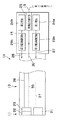
図2に示すように前記内視鏡1の挿入部10の先端部11内には観察部位を照明する照明用LEDを例えば複数配置して構成した照明部21と、この照明部21から出射された照明光によって照らされた観察部位の観察像を対物レンズ22を通して撮像するC−MOSイメージセンサ(以下C−MOSと略記する)23とが設けられている。
【0016】
一方、前記内視鏡1の操作部15内には前記照明部21及び前記C−MOS23に電力を供給する電源部として例えば乾電池等の電池24が配置されている。また、この操作部15の例えば基端部には前記表示装置2へ映像信号を出力する信号出力部となる前記ビデオケーブル16の一端部が接続される映像出力端子部25が設けられている。
【0017】
そして、前記電池24と、前記照明部21及び前記C−MOS23とは中途部で照明用電源ケーブル27及び撮像素子用電源ケーブル28とに分岐する電源供給用ケーブル26によって電気的に接続されている。
【0018】
前記電源供給用ケーブル26の中途部には前記前記照明部21及び前記C−MOS23にショートなどが原因で過剰電流が流れることを防止する電流制限回路29が設けられている。また、前記映像出力端子部25には前記C−MOS23から延出して映像信号を伝送する映像信号伝送ケーブル30が電気的に接続されている。
【0019】
このことにより、本実施形態の内視鏡1に設けた照明部21の照明用LEDは、操作部15内に設けた電池24から供給される電力によって点灯して観察部位を照らす。そして、この照明用LEDによって照らされた観察部位の観察像は、前記対物レンズ22を通してC−MOS23の撮像面に結像し、このC−MOS23内で映像信号に信号処理されて映像出力端子部25に向けて出力されていく。つまり、前記内視鏡1は、前記安全基準条件を満たして観察を行える構成になっている。
【0020】
上述のように構成した電子内視鏡1の作用を説明する。
まず、作業者は、表示装置2を安全領域に配置し、内視鏡1及びビデオケーブル16を危険場所内に持ち込む。
【0021】
次に、前記ビデオケーブル16を映像出力端子部25に接続し、この操作部15に設けられている図示しない電源スイッチを操作する。すると、操作部15に設けられている電池24から電流制限回路29を通して前記C−MOS23及び前記照明部21に電力が供給されていく。
【0022】
このことにより、照明部21より照明光が出射されるとともに、対物レンズ22でとらえた観察像がC−MOS23の撮像面に結像し、このC−MOS23から出力される映像信号が映像信号伝送ケーブル30、映像出力端子部25、ビデオケーブル16を介して表示装置2に伝送される。このことにより、表示装置2の画面上に観察部位の内視鏡画像が表示される。観察者はこの表示装置2の画面に表示される内視鏡画像を見ながら観察等を行うとともに、作業者に操作指示を送って所望の観察を行える。
【0023】
このように、DC28V以下、93mA以下、0.66W以下で動作するC−MOS及び照明用LEDを先端部に設けて電子内視鏡を構成したことにより、危険場所持ち込んで安全に内視鏡観察を行うことができる。
【0024】
また、先端部に設けたC−MOS及び照明用LEDの電源を操作部に設けた電池とすることによって携帯性の大幅な向上を図ることができる。
【0025】
さらに、操作部に電流制限回路を設けたことによって、C−MOS及び照明用LEDに過剰電流が供給されることを確実に防止して電子内視鏡の安全性を図ることができる。
【0026】
なお、図3に示すように前記挿入部10の先端部11に、この先端部11の温度を検出する温度センサ31を設けるとともに、前記照明用電源ケーブル27の中途部にこの温度センサ31から伝送される温度情報にしたがって前記照明部21への電力の供給を制御して照明光量を調整する安全回路32を設けている。このことによって、前記照明部21の発熱が原因で先端部11が所定温度以上に上昇することをなくして、照明部21の発熱による不具合の発生を確実に防止することができる。
【0027】
また、本実施形態においては電源部を電池としているが電源部は電池に限定されるものではなく、電源制限回路を備えた外部電源等であってもよい。電源を外部電源とする場合には、外部電源側で電流値を制御することによって、操作部の構成の更なる簡略化を図ることができる。
【0028】
さらに、本実施形態においては、対物レンズ及び照明部を先端面に設けているが、これら対物レンズ及び照明部側面部等に設ける構成にしてもよい。
【0029】
図4は本発明の第2実施形態に係る電子内視鏡の他の構成を説明する図である。
【0030】
図に示すように本実施形態の電子内視鏡1Aは、先端部11に設けられている前記照明部21に対しては第1電池24aから第1電流制限回路29aを介して照明用電源ケーブル27によって電力が供給され、前記C−MOS23に対しては第2電池24bから第2電流制限回路29bを介して撮像素子用電源ケーブル28によって電力が供給されるようになっている。つまり、照明部21及びC−MOS23に対してそれぞれ独立した回路で構成している。その他の構成は前記第1実施形態と同様であり、同部材には同符合を付して説明を省略する。
【0031】
このように、照明部に対する回路及びC−MOSに対する回路をそれぞれ独立させ、危険場所で使用可能な「DC28V以下、93mA以下、0.66W以下」という安全基準条件をそれぞれの回路で満たす構成としたことにより、照明部に十分な電力を供給して十分な照明光量を得ることができる。その他の作用及び効果は前記第1実施形態と同様である。
【0032】
図5は本発明の第3実施形態に係る電子内視鏡の別の構成を説明する図である。
【0033】
図に示すように本実施形態の電子内視鏡1Bは、操作部15に信号出力部として映像出力端子部25の代わりに危険場所で使用可能な微弱電波や赤外光を出力する送信部33を設けている。また、前記表示装置2の代わりに受信部2aを有する少なくとも1台の表示装置2Aや記録装置(不図示)等を使用する。
【0034】
そして、前記送信部33への電力の供給を第3電池24cによって行っている。なお、この第3電池24cと前記送信部33との間には第3電流制限回路29cが設けられている。また、前記第1電池24a又は第2電池24bを送信部33の電源部にする構成であってもよい。このとき、送信部33と電池24a,24bとの間に電流制限回路を設ける。その他の構成は前記第2実施形態と同様であり、同部材には同符合を付して説明を省略する。
【0035】
このように、操作部に設けた送信部から安全領域に配置されている表示装置等の受信部に信号を伝送して、観察及び記録を行うことができる。また、危険場所と安全領域とを連絡するビデオケーブル等を不用にして内視鏡の可搬性及び操作性及び作業の自由度を大幅に向上させることができる。その他の作用及び効果は前記第1実施形態と同様である。
【0036】
なお、上述した実施形態では電子内視鏡を危険場所で使用される電子内視鏡として説明したが、本実施形態の構成を安全領域で使用する工業用の内視鏡や医療用の内視鏡に適用するようにしてもよい。
【0037】
尚、本発明は、以上述べた実施形態のみに限定されるものではなく、発明の要旨を逸脱しない範囲で種々変形実施可能である。
【0038】
[付記]
以上詳述したような本発明の上記実施形態によれば、以下の如き構成を得ることができる。
【0039】
(1)挿入部の先端部に、光学像が結像する撮像面を有する撮像手段及び観察部位を照らす照明手段を設けた電子内視鏡において、
前記撮像手段は、映像信号を出力するC−MOSイメージセンサであり、前記照明手段は照明光を発する照明用LEDであることを特徴とする電子内視鏡。
【0040】
(2)前記C−MOSイメージセンサ及び前記照明用LEDの電源は、前記挿入部の基端部に配設されている操作部に設けられる電池である付記1記載の電子内視鏡。
【0041】
(3)前記電池を、前記C−MOSイメージセンサ及び前記照明用LEDにそれぞれ対応するように1つずつ前記操作部に設けた付記1記載の電子内視鏡。
【0042】
(4)前記電池と、前記照明部及び前記C−MOSイメージセンサとの間に電流制限回路を設けた付記2又は付記3記載の電子内視鏡。
【0043】
(5)前記挿入部の先端部に、さらに温度センサ及び安全回路を設けた付記1記載の電子内視鏡。
【0044】
(6)前記C−MOSイメージセンサから出力される映像信号は、前記挿入部の基端部に配設されている操作部に設けた信号出力部から表示装置に向けて出力される付記1記載の電子内視鏡。
【0045】
(7)前記信号出力部は、映像出力端子部である付記3記載の電子内視鏡。
【0046】
(8)前記信号出力部は、送信部である付記3記載の電子内視鏡。
【0047】
(9)前記送信部は、単独の電池から電流制限回路を通して供給される電力によって動作する付記8記載の電子内視鏡。
【0048】
(10)前記C−MOSイメージセンサは、安全基準条件を満たして動作する付記1記載の電子内視鏡。
【0049】
(11)前記照明用LEDは、安全基準条件を満たして照明光を発する付記1記載の電子内視鏡。
【0050】
【発明の効果】
以上説明したように本発明によれば、低消費電力で、危険場所における安全基準条件を満たす電子内視鏡を提供することができる。
【図面の簡単な説明】
【図1】図1及び図2は本発明の第1実施形態に係り、図1は本発明の電子内視鏡を備えた内視鏡装置の構成を説明する図
【図2】電子内視鏡の構成を説明する図
【図3】さらに、温度センサと安全回路とを設けた電子内視鏡の構成を説明する図
【図4】電子内視鏡の他の構成を説明する図
【図5】電子内視鏡の別の構成を説明する図
【符号の説明】
1…電子内視鏡
10…挿入部
15…操作部
21…照明部
23…C−MOSイメージセンサ
24…電池
25…映像出力端部
27…照明用電源ケーブル
28…撮像素子用電源ケーブル
29…電流制限回路
30…映像信号伝送ケーブル[0001]
BACKGROUND OF THE INVENTION
The present invention relates to an electronic endoscope that is driven with low power.
[0002]
[Prior art]
In recent years, endoscopes that can observe various organs in a body cavity by inserting an elongated insertion part into a body cavity, or can perform various treatments using a treatment instrument inserted into a treatment instrument channel as necessary are widely used. Has been. Also in the industrial field, industrial endoscopes are widely used for observing and inspecting internal scratches and corrosion of boilers, turbines, engines, chemical plants, and the like.
[0003]
The endoscope used as described above includes an electronic endoscope (hereinafter abbreviated as an endoscope) in which an imaging element such as a CCD that photoelectrically converts an optical image into an image signal is disposed at the distal end portion of an insertion portion. is there. In this endoscope, an observation image of an observation site illuminated by illumination light supplied from a light source device is formed on an imaging surface of an image sensor, and an image signal of the observation image photoelectrically converted by the image sensor is transmitted by an external device. A video signal is generated by transmitting it to a signal processing unit of a certain camera control unit (hereinafter abbreviated as CCU), and an endoscope image is displayed on a monitor screen for observation.
[0004]
For example, in Japanese Patent Laid-Open No. 8-117184, in order to provide an endoscope apparatus that realizes high functionality with a small diameter and a simple configuration by eliminating a light guide fiber made of an optical fiber, an observation site is provided at the distal end. An endoscope apparatus is disclosed that includes a solid-state imaging device that captures an image and a surface-emitting light source that illuminates an observation site.
[0005]
Some endoscopes used in the industrial field are used in hazardous locations (hereinafter referred to as dangerous locations) such as explosive atmospheres, such as chemical plant piping and gas tanks. And the equipment used in this hazardous area must satisfy at least the safety standard condition of “DC28V or less, 93mA or less, 0.66W or less” in order to prevent this equipment from becoming an ignition source.
[0006]
[Problems to be solved by the invention]
However, since the CCD provided in the endoscope has a characteristic that the rising current value generated during driving is high, even if the problem of power consumption can be solved, the above-mentioned current value condition is satisfied. Can not be used, so the problem remains when used in hazardous areas.
[0007]
Further, when the tip is heated by heat of electronic components such as resistors provided near the CCD or heat of illumination light supplied from the light source device, for example, ethyl nitrite having an ignition point of 80 ° C. or 85 ° C. There is a problem that it is difficult to use an electronic endoscope in piping that handles gas that may ignite at low temperatures such as ethyl nitrate.
[0008]
The present invention has been made in view of the above circumstances, and an object thereof is to provide an electronic endoscope that satisfies a safety standard condition in a hazardous area with low power consumption.
[0009]
[Means for Solving the Problems]
The electronic endoscope of the present invention has a C-MOS image sensor that outputs an image signal and an illumination LED that illuminates an observation site, having an imaging surface on which an optical image is formed at the distal end of the insertion portion.
In a circuit for supplying power from the power supply unit to the C-MOS image sensor and the illumination LED, it is possible to suppress an excessive current from flowing from the power supply unit to the C-MOS image sensor or the illumination LED. A current limiting circuit for continuously driving the C-MOS image sensor and the illumination LED so as to be directly below 0.66 W is provided on the operation unit side, and the C-MOS image sensor and the illumination LED are provided. Operates at DC28V or lower, 93mA or lower, 0.66W or lower .
[0010]
According to this configuration, the power consumption of the electronic endoscope is reduced and the electronic endoscope can be used in a dangerous place.
[0011]
DETAILED DESCRIPTION OF THE INVENTION
Embodiments of the present invention will be described below with reference to the drawings.
1 and 2 relate to a first embodiment of the present invention, FIG. 1 is a diagram for explaining the configuration of an electronic endoscope apparatus including the electronic endoscope of the present invention, and FIG. 2 is a configuration of the electronic endoscope. FIG.
[0012]
As shown in FIG. 1, the endoscope apparatus according to the present embodiment includes an illuminating unit configured by disposing an illumination LED as a surface emitting light source as an illuminating unit at a
[0013]
The
[0014]
The C-MOS used as the image pickup means is suitable for high density mounting with all functions as a camera such as a drive signal generation unit, a noise reduction circuit, an output signal level stabilization circuit, an A / D converter, etc. The feature is that the system satisfies the safety standard condition of 93 mA or less and 0.66 W or less as a system including the LED for illumination. In addition, when arrange | positioning the said
[0015]
As shown in FIG. 2, in the
[0016]
On the other hand, a
[0017]
The
[0018]
In the middle of the
[0019]
As a result, the illumination LED of the
[0020]
The operation of the electronic endoscope 1 configured as described above will be described.
First, the worker places the
[0021]
Next, the
[0022]
As a result, illumination light is emitted from the
[0023]
As described above, the electronic endoscope is configured by providing the C-MOS and the illumination LED operating at DC 28 V or less, 93 mA or less, and 0.66 W or less at the distal end portion, so that the endoscope can be safely observed by bringing it into a hazardous area. It can be performed.
[0024]
In addition, by using a battery with the C-MOS and illumination LED provided at the tip as the operation unit, the portability can be greatly improved.
[0025]
Furthermore, by providing a current limiting circuit in the operation unit, it is possible to reliably prevent an excessive current from being supplied to the C-MOS and the illumination LED, thereby improving the safety of the electronic endoscope.
[0026]
As shown in FIG. 3, a
[0027]
In the present embodiment, the power supply unit is a battery, but the power supply unit is not limited to a battery, and may be an external power supply provided with a power supply limiting circuit. When the power source is an external power source, the configuration of the operation unit can be further simplified by controlling the current value on the external power source side.
[0028]
Further, in the present embodiment, the objective lens and the illumination unit are provided on the front end surface, but the objective lens and the illumination unit side surface may be provided.
[0029]
FIG. 4 is a diagram illustrating another configuration of the electronic endoscope according to the second embodiment of the present invention.
[0030]
As shown in the drawing, in the electronic endoscope 1A of the present embodiment, the illumination power supply cable from the
[0031]
In this way, the circuit for the illumination unit and the circuit for the C-MOS are made independent, and each circuit satisfies the safety standard condition of “DC 28 V or less, 93 mA or less, 0.66 W or less” that can be used in hazardous locations. Thus, a sufficient amount of illumination light can be obtained by supplying sufficient power to the illumination unit. Other operations and effects are the same as those in the first embodiment.
[0032]
FIG. 5 is a diagram for explaining another configuration of the electronic endoscope according to the third embodiment of the present invention.
[0033]
As shown in the figure, the electronic endoscope 1B according to the present embodiment transmits a weak radio wave or infrared light that can be used in a dangerous place as a signal output unit to the
[0034]
The
[0035]
As described above, observation and recording can be performed by transmitting a signal from a transmission unit provided in the operation unit to a reception unit such as a display device arranged in the safe area. In addition, it is possible to greatly improve the portability and operability of the endoscope and the degree of freedom of work by eliminating the need for a video cable or the like that connects the dangerous place and the safe area. Other operations and effects are the same as those in the first embodiment.
[0036]
In the above-described embodiment, the electronic endoscope is described as an electronic endoscope used in a hazardous area. However, an industrial endoscope or a medical endoscope that uses the configuration of the present embodiment in a safe area. You may make it apply to a mirror.
[0037]
The present invention is not limited to the above-described embodiments, and various modifications can be made without departing from the spirit of the invention.
[0038]
[Appendix]
According to the embodiment of the present invention as described above in detail, the following configuration can be obtained.
[0039]
(1) In an electronic endoscope in which an imaging unit having an imaging surface on which an optical image is formed and an illumination unit that illuminates an observation site are provided at the distal end of the insertion unit.
The electronic endoscope, wherein the imaging means is a C-MOS image sensor that outputs a video signal, and the illumination means is an illumination LED that emits illumination light.
[0040]
(2) The electronic endoscope according to appendix 1, wherein a power source of the C-MOS image sensor and the illumination LED is a battery provided in an operation unit disposed at a proximal end portion of the insertion unit.
[0041]
(3) The electronic endoscope according to appendix 1, wherein the battery is provided in the operation unit one by one so as to correspond to the C-MOS image sensor and the illumination LED.
[0042]
(4) The electronic endoscope according to
[0043]
(5) The electronic endoscope according to appendix 1, wherein a temperature sensor and a safety circuit are further provided at a distal end portion of the insertion portion.
[0044]
(6) The video signal output from the C-MOS image sensor is output toward a display device from a signal output unit provided in an operation unit disposed at a base end of the insertion unit. Electronic endoscope.
[0045]
(7) The electronic endoscope according to appendix 3, wherein the signal output unit is a video output terminal unit.
[0046]
(8) The electronic endoscope according to appendix 3, wherein the signal output unit is a transmission unit.
[0047]
(9) The electronic endoscope according to appendix 8, wherein the transmission unit is operated by electric power supplied from a single battery through a current limiting circuit.
[0048]
(10) The electronic endoscope according to appendix 1, wherein the C-MOS image sensor operates while satisfying safety standard conditions.
[0049]
(11) The electronic endoscope according to appendix 1, wherein the illumination LED emits illumination light that satisfies a safety standard condition.
[0050]
【The invention's effect】
As described above, according to the present invention, it is possible to provide an electronic endoscope that satisfies a safety standard condition in a dangerous place with low power consumption.
[Brief description of the drawings]
FIG. 1 and FIG. 2 relate to a first embodiment of the present invention, and FIG. 1 is a diagram for explaining the configuration of an endoscope apparatus provided with the electronic endoscope of the present invention. FIG. 3 is a diagram illustrating the configuration of an electronic endoscope provided with a temperature sensor and a safety circuit. FIG. 4 is a diagram illustrating another configuration of the electronic endoscope. 5] A diagram for explaining another configuration of an electronic endoscope [Explanation of symbols]
DESCRIPTION OF SYMBOLS 1 ...
Claims (8)
電源部から前記C−MOSイメージセンサ及び前記照明用LEDに電力を供給する回路中に、前記電源部から前記C−MOSイメージセンサまたは前記照明用LEDに過剰電流が流れることを抑制すると共に、当該C−MOSイメージセンサ及び照明用LEDが直接的に0.66W以下となるように連続して駆動するための電流制限回路を前記操作部側に備え、
前記C−MOSイメージセンサ及び前記照明用LEDは、DC28V以下、93mA以下、0.66W以下で動作することを特徴とする電子内視鏡。The distal end portion of the insertion portion has an imaging surface on which an optical image is formed, and includes a C-MOS image sensor that outputs a video signal and an illumination LED that illuminates the observation site,
In a circuit for supplying power from the power supply unit to the C-MOS image sensor and the illumination LED, it is possible to suppress an excessive current from flowing from the power supply unit to the C-MOS image sensor or the illumination LED. A current limiting circuit for continuously driving the C-MOS image sensor and the LED for illumination so as to be directly below 0.66 W is provided on the operation unit side ,
The electronic endoscope, wherein the C-MOS image sensor and the illumination LED operate at DC 28 V or lower, 93 mA or lower, and 0.66 W or lower .
前記電流制限回路は、前記電池と前記照明用LED及び前記C−MOSイメージセンサとの間、又は前記外部電源の内部に設けられることを特徴とする請求項1に記載の電子内視鏡。The power supply unit for supplying power to the illumination LED and the C-MOS image sensor is a battery provided in an operation unit disposed at a base end portion of the insertion unit, or an external power supply.
The electronic endoscope according to claim 1, wherein the current limiting circuit is provided between the battery, the illumination LED, and the C-MOS image sensor, or inside the external power source.
前記C−MOSイメージセンサ及び前記照明用LEDは、前記電源部より当該C−MOSイメージセンサ及び当該照明用LEDに電力が供給された状態において、予め、DC28V以下、93mA以下、0.66W以下で定義された安全基準条件を満たして動作するシステムとして構成され、前記電池と前記照明用LED及び前記C−MOSイメージセンサとの間、又は前記外部電源の内部には過剰電流が流れることを抑制すると共に、当該C−MOSイメージセンサ及び照明用LEDが直接的に0.66W以下となるように連続して駆動するための電流制限回路を前記操作部側に備えることを特徴とする電子内視鏡。A C-MOS image sensor that has an imaging surface on which an optical image is formed and that outputs an image signal, an illumination LED that illuminates an observation site, the C-MOS image sensor, and the illumination, which are provided at the distal end of the insertion unit An electronic endoscope used in an explosive atmosphere, provided with a battery provided in an operation unit disposed at a base end portion of the insertion portion for supplying electric power to the LED for use or a power source unit as an external power source In the mirror
The C-MOS image sensor and the illumination LED are DC 28 V or less, 93 mA or less, 0.66 W or less in advance in a state where power is supplied from the power supply unit to the C-MOS image sensor and the illumination LED. It is configured as a system that operates under the defined safety standard conditions, and suppresses excessive current from flowing between the battery and the illumination LED and the C-MOS image sensor, or inside the external power supply. And an electronic endoscope comprising a current limiting circuit for continuously driving the C-MOS image sensor and the illumination LED directly at 0.66 W or less on the operation unit side. .
Priority Applications (2)
| Application Number | Priority Date | Filing Date | Title |
|---|---|---|---|
| JP25203499A JP4477168B2 (en) | 1999-09-06 | 1999-09-06 | Electronic endoscope |
| US09/648,026 US6796939B1 (en) | 1999-08-26 | 2000-08-25 | Electronic endoscope |
Applications Claiming Priority (1)
| Application Number | Priority Date | Filing Date | Title |
|---|---|---|---|
| JP25203499A JP4477168B2 (en) | 1999-09-06 | 1999-09-06 | Electronic endoscope |
Related Child Applications (1)
| Application Number | Title | Priority Date | Filing Date |
|---|---|---|---|
| JP2010013109A Division JP4918599B2 (en) | 2010-01-25 | 2010-01-25 | Endoscopic observation method |
Publications (3)
| Publication Number | Publication Date |
|---|---|
| JP2001075021A JP2001075021A (en) | 2001-03-23 |
| JP2001075021A5 JP2001075021A5 (en) | 2006-10-19 |
| JP4477168B2 true JP4477168B2 (en) | 2010-06-09 |
Family
ID=17231667
Family Applications (1)
| Application Number | Title | Priority Date | Filing Date |
|---|---|---|---|
| JP25203499A Expired - Fee Related JP4477168B2 (en) | 1999-08-26 | 1999-09-06 | Electronic endoscope |
Country Status (1)
| Country | Link |
|---|---|
| JP (1) | JP4477168B2 (en) |
Families Citing this family (6)
| Publication number | Priority date | Publication date | Assignee | Title |
|---|---|---|---|---|
| GB2378522B (en) * | 2001-08-08 | 2003-08-13 | Pearpoint Ltd | Integrated camera and lighting device and a method of manufacture thereof |
| JP4855059B2 (en) | 2005-12-08 | 2012-01-18 | オリンパス株式会社 | Endoscope device |
| JP4757044B2 (en) | 2006-01-27 | 2011-08-24 | オリンパス株式会社 | Explosion-proof device drive |
| JP2007252516A (en) * | 2006-03-22 | 2007-10-04 | Olympus Medical Systems Corp | Medical device |
| WO2012160669A1 (en) * | 2011-05-25 | 2012-11-29 | オリンパス株式会社 | Endoscope device |
| WO2019044187A1 (en) * | 2017-09-01 | 2019-03-07 | オリンパス株式会社 | Endoscope insertion part |
-
1999
- 1999-09-06 JP JP25203499A patent/JP4477168B2/en not_active Expired - Fee Related
Also Published As
| Publication number | Publication date |
|---|---|
| JP2001075021A (en) | 2001-03-23 |
Similar Documents
| Publication | Publication Date | Title |
|---|---|---|
| US6796939B1 (en) | Electronic endoscope | |
| JP5344894B2 (en) | Imaging device | |
| US8721524B2 (en) | Endoscope with thin plate-like substrate | |
| JP2012533406A (en) | Endoscopic imaging system | |
| US20160089000A1 (en) | Endoscope | |
| JP2009201684A (en) | Endoscope and medical system | |
| JP4503734B2 (en) | Electronic endoscope | |
| JPH119548A (en) | Portable electronic endoscope | |
| US20210113059A1 (en) | Endoscope apparatus, method of controlling endoscope apparatus and non-transitory computer readable recording medium recording program for controlling endoscope apparatus | |
| JP4477168B2 (en) | Electronic endoscope | |
| CN105592774B (en) | Endoscope lighting system | |
| JP4477167B2 (en) | Electronic endoscope | |
| JP4918599B2 (en) | Endoscopic observation method | |
| JP2934514B2 (en) | TV camera device for endoscope | |
| JP4689206B2 (en) | Electronic endoscope system | |
| WO2014195843A2 (en) | Endoscopic/boroscopic instrument with wireless transmission and charging module | |
| JP4199441B2 (en) | Endoscope | |
| JP4790069B2 (en) | Endoscope | |
| JP2000325305A (en) | Image processing device for endoscope | |
| JPH1156777A (en) | Simplified endoscope | |
| JP2000171725A5 (en) | ||
| JP4388452B2 (en) | Electronic endoscope | |
| JP2761369B2 (en) | Electronic endoscope device | |
| JP5459991B2 (en) | Endoscope system | |
| JP5288909B2 (en) | Endoscope system and switch |
Legal Events
| Date | Code | Title | Description |
|---|---|---|---|
| A521 | Written amendment |
Free format text: JAPANESE INTERMEDIATE CODE: A523 Effective date: 20060905 |
|
| A621 | Written request for application examination |
Free format text: JAPANESE INTERMEDIATE CODE: A621 Effective date: 20060905 |
|
| A977 | Report on retrieval |
Free format text: JAPANESE INTERMEDIATE CODE: A971007 Effective date: 20090422 |
|
| A131 | Notification of reasons for refusal |
Free format text: JAPANESE INTERMEDIATE CODE: A131 Effective date: 20090428 |
|
| A521 | Written amendment |
Free format text: JAPANESE INTERMEDIATE CODE: A523 Effective date: 20090629 |
|
| A131 | Notification of reasons for refusal |
Free format text: JAPANESE INTERMEDIATE CODE: A131 Effective date: 20090901 |
|
| A521 | Written amendment |
Free format text: JAPANESE INTERMEDIATE CODE: A523 Effective date: 20091030 |
|
| A131 | Notification of reasons for refusal |
Free format text: JAPANESE INTERMEDIATE CODE: A131 Effective date: 20091124 |
|
| A521 | Written amendment |
Free format text: JAPANESE INTERMEDIATE CODE: A523 Effective date: 20100122 |
|
| TRDD | Decision of grant or rejection written | ||
| A01 | Written decision to grant a patent or to grant a registration (utility model) |
Free format text: JAPANESE INTERMEDIATE CODE: A01 Effective date: 20100216 |
|
| A01 | Written decision to grant a patent or to grant a registration (utility model) |
Free format text: JAPANESE INTERMEDIATE CODE: A01 |
|
| A61 | First payment of annual fees (during grant procedure) |
Free format text: JAPANESE INTERMEDIATE CODE: A61 Effective date: 20100311 |
|
| FPAY | Renewal fee payment (event date is renewal date of database) |
Free format text: PAYMENT UNTIL: 20130319 Year of fee payment: 3 |
|
| FPAY | Renewal fee payment (event date is renewal date of database) |
Free format text: PAYMENT UNTIL: 20140319 Year of fee payment: 4 |
|
| S531 | Written request for registration of change of domicile |
Free format text: JAPANESE INTERMEDIATE CODE: R313531 |
|
| R350 | Written notification of registration of transfer |
Free format text: JAPANESE INTERMEDIATE CODE: R350 |
|
| LAPS | Cancellation because of no payment of annual fees |