JP4476494B2 - Method and apparatus for monitoring calculation element in automobile - Google Patents
Method and apparatus for monitoring calculation element in automobile Download PDFInfo
- Publication number
- JP4476494B2 JP4476494B2 JP2000612612A JP2000612612A JP4476494B2 JP 4476494 B2 JP4476494 B2 JP 4476494B2 JP 2000612612 A JP2000612612 A JP 2000612612A JP 2000612612 A JP2000612612 A JP 2000612612A JP 4476494 B2 JP4476494 B2 JP 4476494B2
- Authority
- JP
- Japan
- Prior art keywords
- program
- module
- test data
- vehicle
- test
- Prior art date
- Legal status (The legal status is an assumption and is not a legal conclusion. Google has not performed a legal analysis and makes no representation as to the accuracy of the status listed.)
- Expired - Lifetime
Links
Images


Classifications
-
- G—PHYSICS
- G06—COMPUTING; CALCULATING OR COUNTING
- G06F—ELECTRIC DIGITAL DATA PROCESSING
- G06F11/00—Error detection; Error correction; Monitoring
-
- F—MECHANICAL ENGINEERING; LIGHTING; HEATING; WEAPONS; BLASTING
- F02—COMBUSTION ENGINES; HOT-GAS OR COMBUSTION-PRODUCT ENGINE PLANTS
- F02D—CONTROLLING COMBUSTION ENGINES
- F02D41/00—Electrical control of supply of combustible mixture or its constituents
- F02D41/22—Safety or indicating devices for abnormal conditions
-
- F—MECHANICAL ENGINEERING; LIGHTING; HEATING; WEAPONS; BLASTING
- F02—COMBUSTION ENGINES; HOT-GAS OR COMBUSTION-PRODUCT ENGINE PLANTS
- F02D—CONTROLLING COMBUSTION ENGINES
- F02D41/00—Electrical control of supply of combustible mixture or its constituents
- F02D41/24—Electrical control of supply of combustible mixture or its constituents characterised by the use of digital means
- F02D41/26—Electrical control of supply of combustible mixture or its constituents characterised by the use of digital means using computer, e.g. microprocessor
Description
【0001】
発明の技術分野
本発明は、自動車内の計算要素のモニタ方法および装置に関するものである。
【0002】
従来の技術
ドイツ特許公開第4438714号から自動車内の計算要素のモニタ方法および装置が既知であり、そのプログラム構造は少なくとも3つのレベルを有している。第1のレベルに、制御機能、例えば駆動ユニットの出力制御を実行するプログラムが割り当てられている。第2のレベルに、第1のレベルの機能をモニタリングするために使用されるプログラムが割り当てられている。このために、図示の駆動ユニットに対する出力制御の実施態様においては、調節すべき運転変数に対する許容値が、この変数の測定または決定された実際値と比較される。第3のレベルに、第2のレベルに割り当てられているモニタ・プログラムの実行検査のために使用されるプログラムが割り当てられている。この場合、実行検査は、安全性構成要素(モニタ・モジュール)との質問−回答通信の範囲内で行われ、この安全性構成要素(モニタ・モジュール)は、第2のレベルのプログラムの正しい動作を質問−回答通信の結果に基づいて検査する(実行検査)。第2のレベルのプログラムおよび/またはモニタ・モジュールにより少なくとも1つのエラー状態が検出された場合、エラー応答手段が導かれ、このエラー応答手段は、駆動ユニットの制御の例においては、燃料供給の遮断または運転を制限するその他の手段からなっている。
【0003】
第2のレベルのプログラムの機能性のモニタリングを改善するために、ドイツ特許公開第19609242号により、実行検査の他にまたは実行検査の代わりに、命令テストを実行し、この命令テストの範囲内において、選択されたプログラムまたはプログラム部分が所定のテスト・データを用いて計算され、且つ1つまたは複数の計算結果がモニタ・モジュール内でエラー検出のためにビットごとに検査される。
【0004】
既知の方法においては、第1および第2のレベルのプログラム並びに実行検査および命令テストが唯一つの計算要素で実行されることが重要である。この場合、モニタリングを実行する第2のレベルのプログラムは、第1のレベルのプログラムにより処理された入力信号に対して冗長な入力信号を用いても作動するものである。この方式により、センサ装置は二重になり、この場合、種々の車両における種々のセンサに基づく追加のセンサを使用することを回避するために、入力信号の僅か一部のみがモニタリングのために使用されるにすぎない。さらに、機能範囲の増加と共に、特に、例えばガソリン直接噴射機関に対する制御装置におけるような駆動ユニットの出力決定機能の機能範囲の増加と共に、モニタリングの精度は次第に低下する。モニタリングの精度を低下させることがある機能に対する例は、加速ペダル測定器のストッパの学習である。この学習機能により、例えば加速ペダル位置信号のオフセットが変化された場合、モニタリングにおいて終端ストッパの最大公差を考慮することにより、このオフセットが考慮される。この比較的大きい公差範囲は、モニタリングの精度を低下させることがある。
【0005】
計算要素において機能範囲が増加するのにもかかわらず、十分に高いモニタリングの精度が保証される車両内の計算要素に対するモニタリングを提供することが本発明の課題である。
【0006】
この課題は独立請求項の特徴項に記載の特徴により達成される。
発明の利点
個々の車両内の増加する機能範囲および種々のセンサ範囲においても計算要素の機能方法の十分なモニタリングが保証される、自動車内の計算要素に対するモニタリングが提供される。
【0007】
安全性基準が失われることなく追加のモニタ・レベルを節約可能であることが特に有利である。
これに関して、計算要素のモニタリングのための設計経過が簡単になることが特に有利である。その理由は、新しい安全性に関連する各機能がそれに適合する新たなモニタ機能を必要としないからである。したがって、その設計が軽減される。
【0008】
本発明の方法が、多数の出力決定機能が設けられている駆動ユニットの制御と組み合わされていることが特に有利である。
さらに、出力決定機能を調節する適応機能がモニタリングの精度に対していかなる影響も与えないことが特に有利である。
【0009】
所定の計算ステップが命令テストを実行するための機能プログラムから選択されることが特に有利である。その理由は、これにより安全性基準が失われることなく計算作業を低減させることができるからである。
【0010】
上記の方法のほかにさらに、計算要素内の第2のレベルの範囲内で作動する従来技術から既知のモニタリングが設けられていることが特に有利である。
その他の利点が実施態様に関する以下の説明ないし従属請求項から明らかである。
【0011】
以下に、本発明を図面に示す実施態様により詳細に説明する。
実施態様の説明
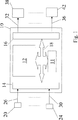
図1は電子式の制御装置10を示し、制御装置10は、少なくとも1つの計算要素12、モニタ・モジュール11、入力回路14、および出力回路16を含む。メモリ構成部分は、計算要素12の一部分であり、またはこれに付属されている。計算要素12は、通信系統18を介してデータ交換のために相互に結合されている。入力回路14には、駆動ユニット、駆動系および/または自動車の測定された運転変数を表わす信号、またはそれからこのような運転変数を導くことが可能な信号が供給される。これらの信号は、測定装置20−24により測定され且つ入力ライン26−30を介して、入力回路14に供給される。さらに、出力回路16を介して、駆動ユニット、駆動系および/または自動車の少なくとも1つの運転変数を調節するための調節要素を操作する信号が出力される。対応する操作変数信号は、ライン32−36を介して調節要素38−42に出力される。
【0012】
入力信号、それから導かれる運転変数および/または内部変数の関数として、計算要素12は、そこで実行されるプログラムの範囲内で、所定の制御方式に従って調節要素を調節する、出力すべき制御変数に対する値を形成する。好ましい実施態様においては、制御ユニット10は自動車駆動ユニットを制御するための制御ユニットである。ここで、既知のように、ドライバにより操作可能な操作要素の位置が測定され、評価され、そして駆動ユニットのトルクに対する目標値が決定される。この目標値から、次に、入力回路14を介して受け取られた、例えば駆動滑り制御、変速機制御等のような他の制御装置の目標値並びに内部で形成された目標値(制限等)を考慮して、トルクに対する目標値が決定される。この目標値は、次に、内燃機関の好ましい実施態様においては、位置制御回路で調節される絞り弁の位置に対する目標値に変換される。さらに、内燃機関の付属機器に応じて、それぞれ他の出力決定機能、例えばターボ・チャージャ、排気ガス戻し、アイドル回転速度制御等の制御が設けられている。さらに、ガソリン直接噴射式内燃機関においては、空気調節のみならず、噴射すべき燃料質量流量の決定、調節すべき空燃比の決定、噴射過程(前噴射、後噴射)の設定、給気可動弁の制御等もまた出力を決定するので、ここでは上記のプログラムのほかに、内燃機関の出力に影響を与える、従って自動車の安全性に影響を与える多数の他のプログラムが設けられている。
【0013】
他の実施態様においては、制御装置10は、自動変速機を、またはブレーキ装置、例えば電動式締付装置を有するブレーキ装置を制御する。これらの装置においてもまた、自動車に対して安全性に関連するプログラムは、例えばブレーキ装置の制御においては、目標ブレーキ力の形成、個々の車輪ブレーキにおける目標ブレーキへの制御、ブレーキ・ペダルの操作信号からのドライバのブレーキ希望の形成等である。同様に、変速機制御においてもまた、安全性に関連する機能が存在する。
【0014】
このような制御装置においては、可能性のある基本的な2つのエラー領域が考慮される。一方で、これは制御ソフトウェアへの変換における定義エラーおよびソフトウェア・エラーであり、他方で、これは制御装置の作動において発生することがある計算要素のハードウェア・エラーである。冒頭記載のモニタ設計により、2つのエラー領域が包含される。以下に記載のモニタ設計は、これら2つのエラー領域の処理を分割することから出発し、この場合、ハードウェア・エラーのみが計算要素でモニタリングされる。これは、場合により実行検査に追加して、安全性に関連する機能を介して命令テストを実行することを可能にする。したがって、レベル2および3に割り当てられているプログラムはなくてもよい。その理由は、モニタリングは、レベル1に存在する安全性に関連する機能を介して実行されるからである(レベル1′)。命令テストおよび場合により実行検査のほかに、計算要素のメモリの機能性を保証するメモリ・テストが設けられている。
【0015】
以下に記載のモニタリングにより検出されない装置エラーおよびソフトウェア・エラーは、設計過程において適切な手段により決定され、また、例えば作業結果の相互検査を用いて複数の共同作業者によって安全性に関連する機能および構成要素を設計することにより回避される。さらに、このタイプのエラーは、設計結果をシミュレーション・モデルと比較することにより検出され、またこのようにしてソフトウェアのエラーが存在しないことが証明される。
【0016】
即ち、計算要素のモニタリングに対してはハードウェア・エラーのみが残っているので、安全性に関連する機能のみ、即ち駆動ユニットの制御においては出力を決定する機能経路、したがってコンピュータ内の出力決定モジュールのみを検査すれば十分である。これらの機能ないしプログラム・モジュールの検査は、命令テストおよび場合により実行検査により行われる。命令テストにおいては、モニタ・モジュール11により、選択されたモジュールに対する選択されたテスト・データが与えられる。モジュールにより実行されたテスト計算は、回答にまとめられ且つモニタ・モジュール11に伝送される。モニタ・モジュール11において、それぞれのテスト・データに付属の結果データを用いて検査がビットごとに行われる。命令テストにおいて計算された結果が期待される結果と一致しなかった場合に、エラー応答が行われ、エラー応答は、例えば別個の構成要素として形成されているモニタ・モジュールにより行われる。制御装置および/または計算要素のメモリ構成要素(RAM、ROM)は、機能モニタリングとは独立にテストされる。
【0017】
このモニタ手段は、安全性に関連する個々のモジュールおよび/または安全性に関連するモジュールの計算ステップが選択されることにより、またコピーとしてまたは時間による切換の範囲内でレベル1′に割り当てられることにより、実行される。一つの実施態様においては、コピーが固有のメモリ構成要素に記憶される。モジュールの部分のみが、機能レベルにコピーされ、或いは命令テストのために使用されるとき、特に加算、減算等のような個々のプログラム・ステップのみが安全性に関連する個々のプログラム・モジュールから選択され且つ命令テストの範囲内で計算されるとき、計算負荷の低減が行われるので、これは有利である。
【0018】
命令テストのテスト計算が、稀にではなく、機能計算と同様に頻繁に行われることが好ましい。最大エラー応答時間がこれにより保証される。その理由は、命令テストにおけるエラー検出が、装置全体に存在するエラー機能と同等化されているからである。
【0019】
さらに、既知のタイプのプログラム実行検査が、レベル1内の安全性に関連する機能に設けられている。このプログラム実行検査の範囲内で、モニタ・モジュールにより乱数発生器を用いて選択された質問が設定され、この質問が選択されたプログラム・モジュールまたはレベル1のプログラム・ステップにより回答され、そして、まとめられた結果がモニタ・モジュールに伝送される。モニタ・モジュールは、この結果を質問に割り当てられている正規な回答と比較する。一致しないとき、エラーが検出される。
【0020】
駆動ユニットの制御の好ましい実施態様においては、安全性に関連する加速ペダル位置信号を評価するためのモジュールは、絞り弁調節装置をモニタリングするためのモジュール、アナログ/ディジタル変換器テストを実行するためのモジュール、目標トルク調整を実行するモジュール、アイドリング制御を実行するモジュール、絞り弁の位置制御のためのモジュール等である。
【0021】
有利な実施態様においては、命令テストおよびプログラム実行検査のほかに、少なくとも安全性に関連するモジュールに関してメモリ構成要素の迅速検査が実行される。この場合、メモリ・テストは短い時間間隔で実行される。メモリ構成要素の適切な検査の例として、補数を有するRAM情報の二重記憶または関連セルを介してのメモリ構成要素の適切なテストを挙げておく。同様のことが、ROMの場合において、制御装置10の前段で行われる。
【0022】
上記のモニタ手段は、計算要素の正しい作動を保証し、且つ計算要素の範囲内のハードウェア・エラーを確実に検出する。追加のプログラム実行検査によりさらにモニタリング精度の改善が達成され、このプログラム実行検査は、モニタ機能と共にメモリ構成要素もさらに追加して検査することにより、全体として計算要素の確実且つ十分なモニタリングを行う。
【0023】
内燃機関の制御の例における好ましい実施態様が、図2により流れ図で示されている。
図2は、計算要素12、並びに分離したモニタ・モジュール11の概略図を示す。安全性に関連する機能ないしプログラム・モジュールが、参照符号110、112および114−118で示されている。変数が通信系統18を介して計算要素に供給され、これらの変数から、図示されていないプログラム・モジュールにおいて、安全性に関連する、即ち出力を決定する、プログラム・モジュールにより使用される変数が決定される。さらに、計算要素から通信系統18を介して調節要素を制御するための制御信号が出力され、制御信号はプログラム・モジュール110−118の少なくとも1つにより決定される。ここで、図示されていないプログラム・モジュール内で制御信号の形成と組み合わせて実行される、必然的な中間ステップおよび中間計算もまた図示されていない。
【0024】
内燃機関の制御の好ましい実施態様においては、選択されたプログラム・モジュール110−118は、内燃機関の出力を決定するプログラムを表わす。例えば、プログラム・モジュール110を用いて加速ペダル位置が測定され且つドライバの希望が形成され、プログラム・モジュール112を用いてトルク調整が実行され、プログラム・モジュール114を用いてアイドリング制御が実行され、およびプログラム・モジュール118を用いて絞り弁の位置制御が実行される。最後のモジュールは次に、他のモジュールの中間結果に基づいて、出力を決定する制御信号を出力する。そのほかに、図示されていない安全性に関連する他のプログラム・モジュール、例えばアナログ/ディジタル変換器のテスト、絞り弁位置のモニタリング、絞り弁位置信号の評価等が存在し、これらは図の参照を容易にするために図2には示されていない。
【0025】
図2はさらに、上記の計算要素12のモニタ方法を示し且つモニタ・モジュール11との相互作用を示している。計算要素12に存在する2つのプログラム・レベル、即ち、制御機能を実行するプログラム(例えば、110−118)に割り当てられているレベル1、並びにモニタ機能の実行の基礎となっているプログラム110−118の部分またはそれらのコピーが割り当てられているレベル1′が示されている。計算要素12は、通信系統18を介して、図2においてライン18aおよび18bで示されているように、モニタ・モジュール11と結合されている。さらに、モニタ・モジュール11は、ライン18cで表わされた通信系統18を介して、エラーの場合に非常運転または制御機能の制限を行うように制御に係合する。
【0026】
図示のプログラム110−118は、安全性に関連して、自動車の運転特性に作用する。その理由は、これらのプログラムが駆動ユニットの出力をドライバの設定とは独立に調節するからである。図示のプログラムは、機能プログラムとしてレベル1に割り当てられ、ここでは制御を実行するために作動される。これらのプログラムを用いて、従来技術から既知の実行検査が行われ、実行検査は、モニタ・モジュール11との質問−回答通信として、モニタ・モジュール11からライン18aを介して起動される。この理由から、プログラム110−118は、計算要素12のモニタ・レベル1′の部分でもある。モニタ・モジュール11の質問に対してまとめられた、選択されたすべてのプログラム・モジュールが共に関係する回答は、実行検査の結果を選択されたプログラムによるメモリ・テストの結果と結合することが可能な結合段を介して、ライン18bによりモニタ・モジュール11に供給される。モニタ・モジュール11は、伝送された結果を、それが正しいかどうかを所定の値を用いて検査し、許容できない偏差が存在する場合にエラー応答手段を(ライン18cを介して)導く。
【0027】
命令テスト122は、冒頭記載の従来技術から既知のように、所定のテスト・データに基づいて行われる。複数のテスト・データ・セットが計算要素12のメモリ内に記憶され且つモニタ・モジュール11により対応の命令を介して選択されることが好ましい。命令テストは、安全性に関連する影響、特に出力を決定する影響を有する選択されたプログラムにより行われる。図示の例においては、これらはプログラム110−118である。実施態様にそれぞれ応じて、全体プログラムは命令テスト122内に統合され、この場合、命令テストに関して完全なプログラムがテスト・データを用いて実行されるか、または、図2に示されているように、選択されたプログラム部分またはプログラム・ステップ1100−1180が実行される。例えば、各プログラムから、所定のプログラム・ステップ、例えば加算ステップ、減算ステップまたは乗算ステップが選択される。選択されたプログラム・ステップまたはプログラム部分は、命令テスト122内にコピーされまたはオリジナル・プログラム内に残り、次に(コピーまたはオリジナルのいずれかで)命令テストのためにテスト・データを用いて実行される。この結果は、結合段120およびライン18bを介して、モニタ・モジュール11に伝送される。命令テストおよび実行検査のほかに、上記のメモリ・テストが実行される。
【0028】
他の実施態様においては、オリジナル・プログラムのコピーまたはそれの部分の代わりに、オリジナル・プログラムそれ自身がテスト計算に使用される。必要な切換手段はレベル1′の部分である。
【0029】
図3に、2つの具体的な実行方法がプログラム110の例で示されている。図3aに示すように、プログラム110は、このようなプログラム・ステップまたはこれからの個々のプログラム・ステップとしてコピーされ、この場合、コピー110bが命令テストの基礎とされる。機能を実行するオリジナル・プログラム110aは影響を受けないままである。
【0030】
図3bに示す第2の実施態様においては、プログラム110はオリジナルとしてのみ存在する。命令テストのための条件(好ましくは時間条件)が発生したとき、スイッチング素子200および202は、点線の位置に切り換えられる。このとき、プログラム110は、供給されたオリジナル・データ(18)の代わりにテスト・データ(18a)で実行され、その結果は、検査のためにモニタ・モジュール11に出力される(18b)。命令テストのための完全なプログラム110の他に、オリジナル・プログラム110のプログラム部分ないしプログラム・ステップが、命令テストの基礎として選択される。
【図面の簡単な説明】
【図1】 図1は、自動車内の少なくとも1つの運転変数、特に駆動ユニットの出力を制御する、計算要素を有する制御装置の全体ブロック回路図を示す。
【図2】 図2には、計算要素の機能性のモニタリングのための一例が流れ図により示されている。
【図3】 図3は、命令テスト・レベルの2つの実施例に対する流れ図を示す。[0001]
TECHNICAL FIELD OF THE INVENTION The present invention relates to a method and apparatus for monitoring computational elements in a motor vehicle.
[0002]
A prior art DE 44 38 714 discloses a method and device for monitoring computational elements in a motor vehicle, the program structure of which has at least three levels. A program for executing a control function, for example, output control of the drive unit, is assigned to the first level. The second level is assigned a program that is used to monitor the function of the first level. For this purpose, in the output control embodiment for the drive unit shown, the tolerance value for the operating variable to be adjusted is compared with the measured or determined actual value of this variable. The third level is assigned a program used for execution check of the monitor program assigned to the second level. In this case, the performance check is performed within the scope of question-answer communication with the safety component (monitor module), which is the correct operation of the second level program. Are inspected based on the result of the question-answer communication (execution inspection). If at least one error condition is detected by the second level program and / or the monitoring module, an error response means is provided, which in the example of controlling the drive unit is a fuel supply cutoff. Or other means of restricting driving.
[0003]
In order to improve the monitoring of the functionality of the second level program, German Patent Publication No. 19609242 performs an instruction test in addition to or instead of an execution test, within the scope of this instruction test. The selected program or program part is calculated using predetermined test data, and one or more calculation results are checked bit by bit in the monitor module for error detection.
[0004]
In the known method, it is important that the first and second level programs and execution checks and instruction tests are executed with only one computational element. In this case, the second level program for executing the monitoring operates even when a redundant input signal is used for the input signal processed by the first level program. With this scheme, the sensor device is duplicated, in which case only a small part of the input signal is used for monitoring in order to avoid using additional sensors based on different sensors in different vehicles. It is only done. Furthermore, the accuracy of monitoring gradually decreases with increasing functional range, in particular with increasing functional range of the output determining function of the drive unit, for example in a control device for a gasoline direct injection engine. An example for a function that can reduce the accuracy of monitoring is the learning of the accelerator pedal stop. For example, when the offset of the accelerator pedal position signal is changed by this learning function, this offset is taken into account by taking into account the maximum tolerance of the terminal stopper in monitoring. This relatively large tolerance range can reduce the accuracy of monitoring.
[0005]
It is an object of the present invention to provide monitoring for a calculation element in a vehicle in which a sufficiently high monitoring accuracy is ensured despite the increased functional range of the calculation element.
[0006]
This object is achieved by the features described in the features of the independent claims.
ADVANTAGES OF THE INVENTION Monitoring is provided for computational elements in the vehicle, which ensures sufficient monitoring of the functional methods of the computational elements even in increasing functional ranges and various sensor ranges within individual vehicles.
[0007]
It is particularly advantageous to be able to save additional monitoring levels without losing safety standards.
In this regard, it is particularly advantageous that the design process for monitoring the computational element is simplified. The reason is that each function related to the new safety does not require a new monitoring function to match it. Therefore, the design is reduced.
[0008]
It is particularly advantageous that the method according to the invention is combined with the control of a drive unit provided with a number of output determining functions.
Furthermore, it is particularly advantageous that the adaptive function for adjusting the power determination function does not have any influence on the accuracy of the monitoring.
[0009]
It is particularly advantageous that the predetermined calculation step is selected from a functional program for executing the instruction test. The reason is that this makes it possible to reduce the calculation work without losing safety standards.
[0010]
In addition to the method described above, it is particularly advantageous to provide monitoring known from the prior art which operates within a second level within the computational element.
Other advantages are apparent from the following description of the embodiments or the dependent claims.
[0011]
Hereinafter, the present invention will be described in detail with reference to embodiments shown in the drawings.
DESCRIPTION OF THE EMBODIMENTS FIG. 1 shows an
[0012]
As a function of the input signal, the operating variables derived therefrom and / or internal variables, the
[0013]
In another embodiment, the
[0014]
In such a control device, two possible basic error areas are considered. On the one hand, this is a definition error and a software error in the conversion to the control software, on the other hand it is a hardware error of the computational element that can occur in the operation of the controller. The monitor design described at the beginning includes two error areas. The monitor design described below starts with splitting the processing of these two error areas, where only hardware errors are monitored in the computational element. This makes it possible to execute instruction tests via functions related to safety, possibly in addition to execution checks. Therefore, there may be no program assigned to levels 2 and 3. The reason is that monitoring is performed through the safety related functions present at level 1 (level 1 '). In addition to instruction tests and possibly execution checks, memory tests are provided to ensure the memory functionality of the computing elements.
[0015]
Equipment errors and software errors that are not detected by monitoring as described below are determined by appropriate means in the design process, and include functions related to safety by multiple collaborators using, for example, cross-checking of work results and Avoided by designing the component. In addition, this type of error is detected by comparing the design results with a simulation model and thus proves that there are no software errors.
[0016]
That is, only hardware errors remain for the monitoring of the computational elements, so only the functions related to safety, i.e. the functional path that determines the output in the control of the drive unit, and thus the output determination module in the computer It is sufficient to inspect only. These functions or program modules are inspected by instruction tests and possibly execution tests. In the instruction test, the
[0017]
This monitoring means is assigned to level 1 'by selecting individual modules relating to safety and / or calculating steps of modules relating to safety and also as a copy or within the scope of switching by time Is executed. In one embodiment, the copy is stored in a unique memory component. When only module parts are copied to the functional level or used for instruction testing, only individual program steps, such as addition, subtraction, etc., are selected from individual program modules relevant to safety This is advantageous because when it is done and calculated within the scope of instruction testing, a reduction in computational load is made.
[0018]
It is preferable that the test calculation of the instruction test is performed not only infrequently but as frequently as the function calculation. This guarantees a maximum error response time. This is because error detection in the instruction test is equivalent to an error function existing in the entire apparatus.
[0019]
In addition, known types of program execution checks are provided for functions related to safety within Level 1. Within the scope of this program execution check, the selected question is set by the monitor module using a random number generator, this question is answered by the selected program module or level 1 program step, and summarized The result is transmitted to the monitor module. The monitor module compares this result with the legitimate answer assigned to the question. When they do not match, an error is detected.
[0020]
In a preferred embodiment of the control of the drive unit, the module for evaluating the accelerator-related accelerator pedal position signal is a module for monitoring the throttle valve adjustment device, for performing an analog / digital converter test A module for executing target torque adjustment, a module for executing idling control, a module for controlling the position of the throttle valve, and the like.
[0021]
In an advantageous embodiment, in addition to instruction tests and program execution checks, a quick check of memory components is performed at least for modules related to safety. In this case, the memory test is performed at short time intervals. Examples of proper testing of memory components include dual storage of RAM information with complements or proper testing of memory components via associated cells. The same thing is performed in the front stage of the
[0022]
The above monitoring means ensures the correct operation of the computational element and reliably detects hardware errors within the computational element. Further improvement in monitoring accuracy is achieved by the additional program execution check, and this program execution check performs a reliable and sufficient monitoring of the calculation elements as a whole by additionally checking the memory components together with the monitoring function.
[0023]
A preferred embodiment in the example of control of an internal combustion engine is shown in flowchart form in FIG.
FIG. 2 shows a schematic diagram of the
[0024]
In a preferred embodiment of the control of the internal combustion engine, the selected program module 110-118 represents a program that determines the output of the internal combustion engine. For example, accelerator pedal position is measured using
[0025]
FIG. 2 further illustrates how the
[0026]
The illustrated program 110-118 affects the driving characteristics of the vehicle in relation to safety. The reason is that these programs adjust the output of the drive unit independently of the driver settings. The program shown is assigned to level 1 as a function program and is here operated to perform control. Using these programs, an execution test known from the prior art is performed, and the execution test is started from the
[0027]
The
[0028]
In other embodiments, the original program itself is used for test calculations instead of a copy of the original program or a portion thereof. The necessary switching means is the level 1 'part.
[0029]
FIG. 3 shows two specific execution methods as an example of the
[0030]
In the second embodiment shown in FIG. 3b, the
[Brief description of the drawings]
FIG. 1 shows an overall block circuit diagram of a control device with computational elements that controls at least one operating variable in a motor vehicle, in particular the output of a drive unit.
FIG. 2 shows a flow diagram of an example for monitoring the functionality of a computational element.
FIG. 3 shows a flow diagram for two examples of instruction test levels.
Claims (10)
前記計算要素(12)の正しい機能を監視するために、複数のプログラム・ステップを持つ少なくとも一つの前記プログラムモジュールが選択され、選択された前記少なくとも一つのプログラム・モジュールが前記計算要素(12)内でテスト・データに基づいて実行され、前記テスト・データ計算の結果がエラー検出のために所定の結果と比較されること、及び、選択された前記プログラム・モジュールが、供給されたオリジナル・データ及びテスト・データに基づいて実行され、その際、前記オリジナル・データの供給と前記テスト・データの供給との間で切替えが行われることを特徴とする、自動車内の計算要素のモニタリングのための方法。 A method for monitoring a computational element (12) in a vehicle, wherein the computational element includes a program module (110-118) that influences driving characteristics of the vehicle, the computational element comprising the program module In accordance with at least one input variable, generating at least one output variable for the control of at least one function of the vehicle, in a method for monitoring a computational element (12) in a vehicle,
To monitor the correct functioning of the computing element (12), at least one of said program modules having a plurality of program steps is selected, the selected at least one program module is the computational element (12) Based on the test data, the result of the test data calculation is compared with a predetermined result for error detection , and the selected program module is supplied with the original data For monitoring the computational elements in the vehicle, characterized in that switching between the supply of the original data and the supply of the test data is performed on the basis of the test data Method.
前記計算要素(12)の正しい機能をモニタリングするために選択された、複数のプログラム・ステップを持つ前記プログラム・モジュールの中の少なくとも1つのモジュール、選択された前記少なくとも1つのモジュール又はそのコピーが、計算要素(12)内でテスト・データに基づいて実行され、該テスト・データの計算の結果がエラー検出のために所定の結果と比較され、選択された前記プログラム・モジュールが、供給されたオリジナル・データ及びテスト・データに基づいて実行され、その際、前記オリジナル・データの供給と前記テスト・データの供給との間で切替えが行われることを特徴とする、自動車内の計算要素のモニタ装置。A monitoring device for a calculation element (12) in an automobile, wherein the calculation element includes a program module (110 to 118) that influences driving characteristics of the automobile, and the calculation element is controlled by the program module. In a monitoring device of a computational element (12) in a motor vehicle that generates at least one output signal to control at least one function of the motor vehicle as a function of at least one input variable;
At least one module of the program modules having a plurality of program steps selected to monitor the correct function of the computing element (12), the selected at least one module or a copy thereof, The calculation element (12) is executed based on the test data, the result of the calculation of the test data is compared with a predetermined result for error detection, and the selected program module is supplied to the original A monitoring device for calculation elements in a vehicle, which is executed on the basis of data and test data, wherein switching between the supply of the original data and the supply of the test data is performed .
Applications Claiming Priority (3)
| Application Number | Priority Date | Filing Date | Title |
|---|---|---|---|
| DE19917208A DE19917208A1 (en) | 1999-04-16 | 1999-04-16 | Testing of a vehicle computer by supplying test data to one or more program modules so that the results can be checked against expected results and an error condition indicated if necessary |
| DE19917208.0 | 1999-04-16 | ||
| PCT/DE2000/001099 WO2000063546A1 (en) | 1999-04-16 | 2000-04-05 | Method and device for monitoring a computing element in a motor vehicle |
Publications (2)
| Publication Number | Publication Date |
|---|---|
| JP2002542424A JP2002542424A (en) | 2002-12-10 |
| JP4476494B2 true JP4476494B2 (en) | 2010-06-09 |
Family
ID=7904784
Family Applications (1)
| Application Number | Title | Priority Date | Filing Date |
|---|---|---|---|
| JP2000612612A Expired - Lifetime JP4476494B2 (en) | 1999-04-16 | 2000-04-05 | Method and apparatus for monitoring calculation element in automobile |
Country Status (8)
| Country | Link |
|---|---|
| US (1) | US6879891B1 (en) |
| EP (1) | EP1175557B1 (en) |
| JP (1) | JP4476494B2 (en) |
| KR (1) | KR100704322B1 (en) |
| BR (1) | BR0010662A (en) |
| DE (2) | DE19917208A1 (en) |
| RU (1) | RU2243395C2 (en) |
| WO (1) | WO2000063546A1 (en) |
Cited By (1)
| Publication number | Priority date | Publication date | Assignee | Title |
|---|---|---|---|---|
| KR20130054834A (en) * | 2011-11-17 | 2013-05-27 | 콘티넨탈 오토모티브 시스템 주식회사 | Method for simulating about automatic transmission control |
Families Citing this family (14)
| Publication number | Priority date | Publication date | Assignee | Title |
|---|---|---|---|---|
| US7379731B2 (en) * | 2001-05-14 | 2008-05-27 | Ntt Docomo Inc. | System for managing program applications storable in a mobile terminal |
| JP4348950B2 (en) * | 2003-01-23 | 2009-10-21 | 株式会社デンソー | Electronic control unit |
| US7612464B2 (en) * | 2005-06-23 | 2009-11-03 | Denso Corporation | Electronic control system with malfunction monitor |
| US8174512B2 (en) | 2006-06-02 | 2012-05-08 | Immersion Corporation | Hybrid haptic device utilizing mechanical and programmable haptic effects |
| DE102006037124A1 (en) * | 2006-08-09 | 2008-02-14 | Daimler Ag | Drive system for a drive unit of a motor vehicle |
| JP4981743B2 (en) | 2008-05-08 | 2012-07-25 | 三菱重工業株式会社 | Diesel engine fuel control system |
| EP2513456B1 (en) * | 2009-12-18 | 2015-02-25 | Conti Temic microelectronic GmbH | Monitoring computer in a control device |
| KR101205654B1 (en) | 2011-09-30 | 2012-11-27 | 주식회사 케피코 | Monitoring method for external torque demand by engine control unit |
| DE102011086729A1 (en) | 2011-11-21 | 2013-05-23 | Robert Bosch Gmbh | Method for monitoring motor drive system for e.g. diesel engine mounted in motor car, involves detecting error in overrun mode, if overrun maximum tolerable control variable is smaller than read-back control variable of power amplifier |
| KR102083839B1 (en) * | 2013-07-25 | 2020-03-03 | 현대모비스 주식회사 | Memory protection apparatus and method of motor driven power steering system |
| US10018267B2 (en) | 2016-03-11 | 2018-07-10 | Ford Global Technologies, Llc | Vehicle transmission control module reset detection and mitigation |
| JP6540561B2 (en) * | 2016-03-14 | 2019-07-10 | オムロン株式会社 | Evaluation system, evaluation program and evaluation method |
| EP3309721A1 (en) * | 2016-09-23 | 2018-04-18 | KPIT Technologies Ltd. | Autonomous system validation |
| KR102213676B1 (en) | 2019-12-19 | 2021-02-05 | 현대오트론 주식회사 | Terminal apparatus for autosar system with arithmetic operation supervision function and arithmetic operation supervision method of autosar system |
Family Cites Families (15)
| Publication number | Priority date | Publication date | Assignee | Title |
|---|---|---|---|---|
| JPS5963344A (en) * | 1982-10-01 | 1984-04-11 | Fuji Heavy Ind Ltd | Self-diagnosis system for internal-combustion engine |
| JPS5963343A (en) * | 1982-10-01 | 1984-04-11 | Fuji Heavy Ind Ltd | Self-diagnosis system for internal-combustion engine |
| US4598355A (en) * | 1983-10-27 | 1986-07-01 | Sundstrand Corporation | Fault tolerant controller |
| IT1208538B (en) * | 1985-05-14 | 1989-07-10 | Alfa Romeo Spa | DEVICE AND SELF-DIAGNOSIS PROCEDURE OF A MICROCALCULATOR CONTROL SYSTEM FOR A C.I.MOTOR OF A VEHICLE. |
| US5043984A (en) * | 1987-04-14 | 1991-08-27 | Japan Electronic Control Systems Co., Ltd. | Method and system for inspecting microprocessor-based unit and/or component thereof |
| US5182755A (en) * | 1987-06-19 | 1993-01-26 | Diesel Kiki Co., Ltd. | Malfunction checking system for controller |
| US5121324A (en) * | 1989-12-21 | 1992-06-09 | Mack Trucks, Inc. | Motor vehicle magagement and control system including solenoid actuated fuel injection timing control |
| CA2133318A1 (en) * | 1992-04-28 | 1993-11-11 | Christopher John Glenn | Control means for electrically driven vehicules |
| US5372410A (en) * | 1994-02-02 | 1994-12-13 | National Semiconductor Corporation | Anti-lock braking system |
| DE4438714A1 (en) | 1994-10-29 | 1996-05-02 | Bosch Gmbh Robert | Method and device for controlling the drive unit of a vehicle |
| US5687081A (en) * | 1994-12-30 | 1997-11-11 | Crown Equipment Corporation | Lift truck control system |
| SE510029C2 (en) * | 1995-10-03 | 1999-04-12 | Volvo Ab | Diagnostic system in a motor operating system as well as a diagnostic function module (DF module) in a motor operating system |
| DE19609242A1 (en) | 1996-03-09 | 1997-09-11 | Bosch Gmbh Robert | Method and device for controlling a drive unit of a vehicle |
| KR100500721B1 (en) * | 1996-03-14 | 2005-11-25 | 루크 게트리에베시스템 게엠베하 | Vehicle and control method |
| DE19653429C2 (en) * | 1996-12-20 | 1998-10-15 | Siemens Ag | Method for checking the functionality of a computing unit |
-
1999
- 1999-04-16 DE DE19917208A patent/DE19917208A1/en not_active Withdrawn
-
2000
- 2000-04-05 BR BR0010662-3A patent/BR0010662A/en not_active IP Right Cessation
- 2000-04-05 WO PCT/DE2000/001099 patent/WO2000063546A1/en active IP Right Grant
- 2000-04-05 DE DE50011170T patent/DE50011170D1/en not_active Expired - Lifetime
- 2000-04-05 EP EP00926714A patent/EP1175557B1/en not_active Expired - Lifetime
- 2000-04-05 JP JP2000612612A patent/JP4476494B2/en not_active Expired - Lifetime
- 2000-04-05 KR KR1020017013142A patent/KR100704322B1/en active IP Right Grant
- 2000-04-05 RU RU2001130344/06A patent/RU2243395C2/en not_active IP Right Cessation
- 2000-04-15 US US09/958,979 patent/US6879891B1/en not_active Expired - Lifetime
Cited By (2)
| Publication number | Priority date | Publication date | Assignee | Title |
|---|---|---|---|---|
| KR20130054834A (en) * | 2011-11-17 | 2013-05-27 | 콘티넨탈 오토모티브 시스템 주식회사 | Method for simulating about automatic transmission control |
| KR101894311B1 (en) | 2011-11-17 | 2018-09-03 | 콘티넨탈 오토모티브 시스템 주식회사 | Method for simulating about automatic transmission control |
Also Published As
| Publication number | Publication date |
|---|---|
| KR20020007370A (en) | 2002-01-26 |
| US6879891B1 (en) | 2005-04-12 |
| EP1175557B1 (en) | 2005-09-14 |
| BR0010662A (en) | 2002-02-05 |
| RU2243395C2 (en) | 2004-12-27 |
| EP1175557A1 (en) | 2002-01-30 |
| KR100704322B1 (en) | 2007-04-09 |
| DE50011170D1 (en) | 2005-10-20 |
| DE19917208A1 (en) | 2000-10-19 |
| JP2002542424A (en) | 2002-12-10 |
| WO2000063546A1 (en) | 2000-10-26 |
Similar Documents
| Publication | Publication Date | Title |
|---|---|---|
| JP4476494B2 (en) | Method and apparatus for monitoring calculation element in automobile | |
| JPH10507805A (en) | Vehicle drive unit control method and device | |
| US6125322A (en) | Method and device for controlling a vehicle drive unit | |
| US7181334B2 (en) | Method and apparatus to diagnose intake airflow | |
| US7082925B2 (en) | Electronic throttle control with throttle position sensor system and air flow indicators | |
| JP2005520087A (en) | Method and apparatus for monitoring torque of vehicle drive unit | |
| JP2006190131A (en) | Evaluation device for control system, verification device used for the evaluation device, evaluation method for control system and computer program used therefor | |
| US9091615B2 (en) | Method for monitoring the functional software of control devices in a control device system | |
| US7248932B2 (en) | Electronic control unit | |
| CN110821692A (en) | Oxygen sensor diagnostics | |
| JP3835312B2 (en) | Electronic control device for vehicle | |
| JPH06241105A (en) | Method and equipment for controlling internal combustion engine | |
| EP0796988B1 (en) | Method of diagnosing the efficiency of an exhaust gas stoichiometric composition sensor placed downstream of a catalytic converter | |
| US6332452B1 (en) | Method for torque monitoring in the case of Otto engines in motor vehicles | |
| JP2006234431A (en) | Test apparatus and vehicle produced using same | |
| US6654680B2 (en) | CPU diagnosing device and method | |
| US6263858B1 (en) | Powertrain output monitor | |
| GB2391333A (en) | Method and apparatus for selecting between two sensor output signals in an electronic throttle system. | |
| JP3411619B2 (en) | Function test method of vehicle actuator | |
| US6789525B2 (en) | Failure diagnosis apparatus for throttle valve actuating device | |
| CN114643977A (en) | Engine control method and device, vehicle control unit and vehicle | |
| JPH1136927A (en) | Vehicle brake device | |
| US7997066B2 (en) | Method for monitoring the functionality of the heating of a catalytic converter situated in an exhaust system of an internal combustion engine | |
| JP5428960B2 (en) | Internal combustion engine | |
| KR20180067265A (en) | Apparatus and method for controlling engine |
Legal Events
| Date | Code | Title | Description |
|---|---|---|---|
| A529 | Written submission of copy of amendment under article 34 pct |
Free format text: JAPANESE INTERMEDIATE CODE: A529 Effective date: 20011010 |
|
| A621 | Written request for application examination |
Free format text: JAPANESE INTERMEDIATE CODE: A621 Effective date: 20070329 |
|
| A621 | Written request for application examination |
Free format text: JAPANESE INTERMEDIATE CODE: A621 Effective date: 20070329 |
|
| A131 | Notification of reasons for refusal |
Free format text: JAPANESE INTERMEDIATE CODE: A131 Effective date: 20081112 |
|
| A601 | Written request for extension of time |
Free format text: JAPANESE INTERMEDIATE CODE: A601 Effective date: 20090210 |
|
| A602 | Written permission of extension of time |
Free format text: JAPANESE INTERMEDIATE CODE: A602 Effective date: 20090218 |
|
| A521 | Request for written amendment filed |
Free format text: JAPANESE INTERMEDIATE CODE: A523 Effective date: 20090511 |
|
| A02 | Decision of refusal |
Free format text: JAPANESE INTERMEDIATE CODE: A02 Effective date: 20090803 |
|
| A521 | Request for written amendment filed |
Free format text: JAPANESE INTERMEDIATE CODE: A523 Effective date: 20091203 |
|
| A911 | Transfer to examiner for re-examination before appeal (zenchi) |
Free format text: JAPANESE INTERMEDIATE CODE: A911 Effective date: 20100118 |
|
| TRDD | Decision of grant or rejection written | ||
| A01 | Written decision to grant a patent or to grant a registration (utility model) |
Free format text: JAPANESE INTERMEDIATE CODE: A01 Effective date: 20100209 |
|
| A01 | Written decision to grant a patent or to grant a registration (utility model) |
Free format text: JAPANESE INTERMEDIATE CODE: A01 |
|
| A61 | First payment of annual fees (during grant procedure) |
Free format text: JAPANESE INTERMEDIATE CODE: A61 Effective date: 20100310 |
|
| R150 | Certificate of patent or registration of utility model |
Ref document number: 4476494 Country of ref document: JP Free format text: JAPANESE INTERMEDIATE CODE: R150 Free format text: JAPANESE INTERMEDIATE CODE: R150 |
|
| FPAY | Renewal fee payment (event date is renewal date of database) |
Free format text: PAYMENT UNTIL: 20130319 Year of fee payment: 3 |
|
| FPAY | Renewal fee payment (event date is renewal date of database) |
Free format text: PAYMENT UNTIL: 20130319 Year of fee payment: 3 |
|
| FPAY | Renewal fee payment (event date is renewal date of database) |
Free format text: PAYMENT UNTIL: 20140319 Year of fee payment: 4 |
|
| R250 | Receipt of annual fees |
Free format text: JAPANESE INTERMEDIATE CODE: R250 |
|
| R250 | Receipt of annual fees |
Free format text: JAPANESE INTERMEDIATE CODE: R250 |
|
| R250 | Receipt of annual fees |
Free format text: JAPANESE INTERMEDIATE CODE: R250 |
|
| R250 | Receipt of annual fees |
Free format text: JAPANESE INTERMEDIATE CODE: R250 |
|
| R250 | Receipt of annual fees |
Free format text: JAPANESE INTERMEDIATE CODE: R250 |
|
| R250 | Receipt of annual fees |
Free format text: JAPANESE INTERMEDIATE CODE: R250 |
|
| R250 | Receipt of annual fees |
Free format text: JAPANESE INTERMEDIATE CODE: R250 |
|
| R250 | Receipt of annual fees |
Free format text: JAPANESE INTERMEDIATE CODE: R250 |
|
| EXPY | Cancellation because of completion of term |