JP4475815B2 - Dispensing device for containers and method for producing and filling containers with dosing and / or filling heads - Google Patents
Dispensing device for containers and method for producing and filling containers with dosing and / or filling heads Download PDFInfo
- Publication number
- JP4475815B2 JP4475815B2 JP2000586454A JP2000586454A JP4475815B2 JP 4475815 B2 JP4475815 B2 JP 4475815B2 JP 2000586454 A JP2000586454 A JP 2000586454A JP 2000586454 A JP2000586454 A JP 2000586454A JP 4475815 B2 JP4475815 B2 JP 4475815B2
- Authority
- JP
- Japan
- Prior art keywords
- container
- metering device
- pump
- piston
- neck
- Prior art date
- Legal status (The legal status is an assumption and is not a legal conclusion. Google has not performed a legal analysis and makes no representation as to the accuracy of the status listed.)
- Expired - Lifetime
Links
Images


Classifications
-
- B—PERFORMING OPERATIONS; TRANSPORTING
- B05—SPRAYING OR ATOMISING IN GENERAL; APPLYING FLUENT MATERIALS TO SURFACES, IN GENERAL
- B05B—SPRAYING APPARATUS; ATOMISING APPARATUS; NOZZLES
- B05B11/00—Single-unit hand-held apparatus in which flow of contents is produced by the muscular force of the operator at the moment of use
-
- G—PHYSICS
- G01—MEASURING; TESTING
- G01F—MEASURING VOLUME, VOLUME FLOW, MASS FLOW OR LIQUID LEVEL; METERING BY VOLUME
- G01F11/00—Apparatus requiring external operation adapted at each repeated and identical operation to measure and separate a predetermined volume of fluid or fluent solid material from a supply or container, without regard to weight, and to deliver it
- G01F11/28—Apparatus requiring external operation adapted at each repeated and identical operation to measure and separate a predetermined volume of fluid or fluent solid material from a supply or container, without regard to weight, and to deliver it with stationary measuring chambers having constant volume during measurement
- G01F11/286—Apparatus requiring external operation adapted at each repeated and identical operation to measure and separate a predetermined volume of fluid or fluent solid material from a supply or container, without regard to weight, and to deliver it with stationary measuring chambers having constant volume during measurement where filling of the measuring chamber is effected by squeezing a supply container that is in fluid connection with the measuring chamber and excess fluid is sucked back from the measuring chamber during relaxation of the supply container
-
- B—PERFORMING OPERATIONS; TRANSPORTING
- B05—SPRAYING OR ATOMISING IN GENERAL; APPLYING FLUENT MATERIALS TO SURFACES, IN GENERAL
- B05B—SPRAYING APPARATUS; ATOMISING APPARATUS; NOZZLES
- B05B11/00—Single-unit hand-held apparatus in which flow of contents is produced by the muscular force of the operator at the moment of use
- B05B11/0005—Components or details
- B05B11/0037—Containers
-
- B—PERFORMING OPERATIONS; TRANSPORTING
- B05—SPRAYING OR ATOMISING IN GENERAL; APPLYING FLUENT MATERIALS TO SURFACES, IN GENERAL
- B05B—SPRAYING APPARATUS; ATOMISING APPARATUS; NOZZLES
- B05B11/00—Single-unit hand-held apparatus in which flow of contents is produced by the muscular force of the operator at the moment of use
- B05B11/0005—Components or details
- B05B11/0097—Means for filling or refilling the sprayer
-
- B—PERFORMING OPERATIONS; TRANSPORTING
- B05—SPRAYING OR ATOMISING IN GENERAL; APPLYING FLUENT MATERIALS TO SURFACES, IN GENERAL
- B05B—SPRAYING APPARATUS; ATOMISING APPARATUS; NOZZLES
- B05B11/00—Single-unit hand-held apparatus in which flow of contents is produced by the muscular force of the operator at the moment of use
- B05B11/01—Single-unit hand-held apparatus in which flow of contents is produced by the muscular force of the operator at the moment of use characterised by the means producing the flow
- B05B11/10—Pump arrangements for transferring the contents from the container to a pump chamber by a sucking effect and forcing the contents out through the dispensing nozzle
- B05B11/1001—Piston pumps
- B05B11/1009—Piston pumps actuated by a lever
- B05B11/1011—Piston pumps actuated by a lever without substantial movement of the nozzle in the direction of the pressure stroke
-
- B—PERFORMING OPERATIONS; TRANSPORTING
- B05—SPRAYING OR ATOMISING IN GENERAL; APPLYING FLUENT MATERIALS TO SURFACES, IN GENERAL
- B05B—SPRAYING APPARATUS; ATOMISING APPARATUS; NOZZLES
- B05B11/00—Single-unit hand-held apparatus in which flow of contents is produced by the muscular force of the operator at the moment of use
- B05B11/01—Single-unit hand-held apparatus in which flow of contents is produced by the muscular force of the operator at the moment of use characterised by the means producing the flow
- B05B11/10—Pump arrangements for transferring the contents from the container to a pump chamber by a sucking effect and forcing the contents out through the dispensing nozzle
- B05B11/1001—Piston pumps
- B05B11/1015—Piston pumps actuated without substantial movement of the nozzle in the direction of the pressure stroke
-
- B—PERFORMING OPERATIONS; TRANSPORTING
- B05—SPRAYING OR ATOMISING IN GENERAL; APPLYING FLUENT MATERIALS TO SURFACES, IN GENERAL
- B05B—SPRAYING APPARATUS; ATOMISING APPARATUS; NOZZLES
- B05B11/00—Single-unit hand-held apparatus in which flow of contents is produced by the muscular force of the operator at the moment of use
- B05B11/01—Single-unit hand-held apparatus in which flow of contents is produced by the muscular force of the operator at the moment of use characterised by the means producing the flow
- B05B11/10—Pump arrangements for transferring the contents from the container to a pump chamber by a sucking effect and forcing the contents out through the dispensing nozzle
- B05B11/1042—Components or details
- B05B11/1064—Pump inlet and outlet valve elements integrally formed of a deformable material
-
- B—PERFORMING OPERATIONS; TRANSPORTING
- B05—SPRAYING OR ATOMISING IN GENERAL; APPLYING FLUENT MATERIALS TO SURFACES, IN GENERAL
- B05B—SPRAYING APPARATUS; ATOMISING APPARATUS; NOZZLES
- B05B11/00—Single-unit hand-held apparatus in which flow of contents is produced by the muscular force of the operator at the moment of use
- B05B11/01—Single-unit hand-held apparatus in which flow of contents is produced by the muscular force of the operator at the moment of use characterised by the means producing the flow
- B05B11/10—Pump arrangements for transferring the contents from the container to a pump chamber by a sucking effect and forcing the contents out through the dispensing nozzle
- B05B11/1042—Components or details
- B05B11/1073—Springs
- B05B11/1074—Springs located outside pump chambers
-
- B—PERFORMING OPERATIONS; TRANSPORTING
- B05—SPRAYING OR ATOMISING IN GENERAL; APPLYING FLUENT MATERIALS TO SURFACES, IN GENERAL
- B05B—SPRAYING APPARATUS; ATOMISING APPARATUS; NOZZLES
- B05B11/00—Single-unit hand-held apparatus in which flow of contents is produced by the muscular force of the operator at the moment of use
- B05B11/01—Single-unit hand-held apparatus in which flow of contents is produced by the muscular force of the operator at the moment of use characterised by the means producing the flow
- B05B11/10—Pump arrangements for transferring the contents from the container to a pump chamber by a sucking effect and forcing the contents out through the dispensing nozzle
- B05B11/1042—Components or details
- B05B11/1073—Springs
- B05B11/1077—Springs characterised by a particular shape or material
-
- B—PERFORMING OPERATIONS; TRANSPORTING
- B65—CONVEYING; PACKING; STORING; HANDLING THIN OR FILAMENTARY MATERIAL
- B65D—CONTAINERS FOR STORAGE OR TRANSPORT OF ARTICLES OR MATERIALS, e.g. BAGS, BARRELS, BOTTLES, BOXES, CANS, CARTONS, CRATES, DRUMS, JARS, TANKS, HOPPERS, FORWARDING CONTAINERS; ACCESSORIES, CLOSURES, OR FITTINGS THEREFOR; PACKAGING ELEMENTS; PACKAGES
- B65D47/00—Closures with filling and discharging, or with discharging, devices
- B65D47/04—Closures with discharging devices other than pumps
- B65D47/20—Closures with discharging devices other than pumps comprising hand-operated members for controlling discharge
- B65D47/24—Closures with discharging devices other than pumps comprising hand-operated members for controlling discharge with poppet valves or lift valves, i.e. valves opening or closing a passageway by a relative motion substantially perpendicular to the plane of the seat
- B65D47/245—Closures with discharging devices other than pumps comprising hand-operated members for controlling discharge with poppet valves or lift valves, i.e. valves opening or closing a passageway by a relative motion substantially perpendicular to the plane of the seat the valve being opened or closed by actuating a stopper-type element
- B65D47/247—Closures with discharging devices other than pumps comprising hand-operated members for controlling discharge with poppet valves or lift valves, i.e. valves opening or closing a passageway by a relative motion substantially perpendicular to the plane of the seat the valve being opened or closed by actuating a stopper-type element moving linearly, i.e. without rotational motion
-
- B—PERFORMING OPERATIONS; TRANSPORTING
- B05—SPRAYING OR ATOMISING IN GENERAL; APPLYING FLUENT MATERIALS TO SURFACES, IN GENERAL
- B05B—SPRAYING APPARATUS; ATOMISING APPARATUS; NOZZLES
- B05B11/00—Single-unit hand-held apparatus in which flow of contents is produced by the muscular force of the operator at the moment of use
- B05B11/0005—Components or details
- B05B11/0008—Sealing or attachment arrangements between sprayer and container
Abstract
Description
【0001】
(技術分野)
本発明は、流体の適量に分けられる計量配分用容器に繋がれ、少なくとも1つの開口部、および開口部と協働し開口部を閉じる位置と開口部を空けた状態にしておくための位置の間で可動である少なくとも1つの閉鎖部材、を備える計量配分装置に関する。このような計量配分装置は、例えば、水の瓶または飲用瓶用のヘッドという形で知られている。
【0002】
(背景技術)
用語「流体」は、本文では、任意の気体ではない流れる媒体を意味し、したがって細かく分散された粉末状の固形物質と同様に液体も意味する、と理解される。
【0003】
既知の計量配分装置は、概して、解放自在に容器に繋がれており、例えば容器が形成され、充填された後に容器の首にネジ付けられる。独立した装置を形成する計量配分装置は、概して別個に形成されるか、あるいは多くの構成部品から組み立てられる。
【0004】
既知の計量配分装置は、このようにして、それが相対的に多数の構成部品を有し、(形成および充填された)容器とのその組立ての両方が相対的に困難であるという欠点を持つ。計量配分装置の製造および組立ては、これにより高価で、時間を消費し、ますます多くの数のこのような瓶が使用されるという特定の欠点を表す。
【0005】
したがって、本発明は、その目的のために、そこでは前述された欠点が発生しない、前述された型の容器の計量配分装置を提供しなければならない。本発明に従って、これは、計量配分装置の少なくとも一部が容器の首部に前もって形成され、計量配分装置の残りの部分がそれに繋がれるという点で達成される。計量配分装置の一部を容器の首部に事前に既に固定しておくことにより、計量配分装置の組立てが容器への計量配分装置の取付けと一致し、それにより、必要な全操作が少なくて済むことが達成される。加えて、計量配分装置の前記残りの部分は、それが独立したパーツ(部品)として使用されたり取り扱われることはなく、従ってその強度および剛性を容器から引き出すことができるため、従来の計量配分装置におけるよりも、より軽量かつより簡略な形を取ることができる。
【0006】
容器の首部に前もって形成される計量配分装置の一部は、好ましくはこの首部と一体化して形成される。このようにして、別個の構成部品の数が削減され、組立てはこのようにして簡略化される。構成部品数の追加の削減は、首部も容器と一体化して形成されるときに得られる。
【0007】
前記首部に前もって形成される計量配分装置の一部は、例えば、閉鎖部材をその位置の少なくとも1つに固定して保持するための手段、あるいはその位置の1つに閉鎖部材を付勢するための手段を備えることがある。このような付勢手段は、有利なことに少なくとも1つのばねを備えることがある。
【0008】
別の実施態様では、計量配分装置は、さらに、容器と開口部の間に配列される少なくとも1つのポンプを含み、前記ポンプは吸込み側および圧縮側を有し、前記計量配分装置は、さらにその動作のためのポンプに繋がれる可動手段、容器から流体を供給するためにポンプの吸込み側に繋がれる手段、およびポンプの圧縮側に繋がれる少なくとも1つの吐出しノズルを備える。計量配分装置は、このようにして、例えば洗剤用のスプレーボトルから知られているような噴霧器ヘッドを形成する。
【0009】
従来の技術による噴霧器ヘッドは、固定され、通常容器または瓶の首部にネジ付けられてよく、その中に手動で操作可能なピストンポンプが配置される本体を備える。ポンプを操作するために、トリガは本体に枢動可能に繋がれる。ポンプの吸込み側は、かなりの長さ、通常、底部近くの位置まで瓶の中に伸び、それを通して、典型的には液体である流体が瓶の中から引き出されてよい管に繋がれる。ポンプの圧縮側は導管を通って噴霧器ヘッドの吐出しノズルに繋がれる。典型的には付勢ばねである戻り要素は、ピストンをポンプストロークの最後でその休止位置に強制的に戻すようにポンプ内に配列される。従来の技術による噴霧器ヘッドは、通常、瓶が完全に充填された後に、充填ラインで瓶にネジ止めされる。
【0010】
この従来の噴霧器ヘッドは、相対的に多くの数のパーツ(部品)を有し、組み立てるのが相対的に困難であるという欠点を有する。このようにして、噴霧器ヘッドの製造と組立ての両方は高価で、時間がかかるものであり、使用されているスプレーボトルの増加する数を考えて特に不便である。さらに、従来の技術による噴霧器ヘッドの多様なパーツ(部品)はさまざまな材料から作られており、それがスプレーボトルを取り扱い、それが廃棄された後にリサイクルする上で問題を提起する。
【0011】
前述の欠点は、いま、噴霧器ヘッドの少なくとも一部が容器とともに前もって形成され、噴霧器ヘッドの残りの部分がそれに取り付けられるという事実により、本発明に従った計量配分装置または噴霧器ヘッドにおいては取り除かれる。
【0012】
容器とともに前もって形成された計量配分装置の前記一部は、有利なことに動作手段の少なくとも一部を備えていてもよい。例えば、ポンプがピストンポンプであり、ポンプのピストンがそれを休止の位置に付勢するための手段に繋がれるとき、有利なことに少なくとも1つのばねを備えていてもよいのであるが、これらのピストン付勢手段は、好ましくは容器に取り付けられる。それから、ばねが撓みおよび/またはねじりばねであるときに、構造上簡略な実施態様が得られる。
【0013】
計量配分装置の組立てを簡略化し、その機能を改善するために、ピストン付勢手段が、ポンプの動作手段との協働のために有利に適応される。従って、ピストン付勢手段は、ポンプ内に伸びたりポンプ内で配列される必要はない。このようにして、従来のピストン付勢ばねで占有されたポンプ内の空気で満たされた空間が抑制され、それにより汲み上げ作用が改善される。さらに、ピストン付勢手段用の材料の選択は、これらが流体と接触しないため重要性が低い。
【0014】
このケースでは、好ましくは、動作手段のすべての移動にピストンを従わせるために、動作手段が、張力および圧縮を受けて固定されるように、例えばピストンにパチンと嵌められるように、ピストンに繋がれることが注記される。
【0015】
ポンプは、有利なことに、動作手段が可動で繋がれるハウジングを有する。それから、組み立てやすい計量配分装置は、動作手段が、ポンプハウジングの上に枢動可能にパチンと嵌められるトリガを備えるときに得られる。
【0016】
本実施態様の変形では、ポンプは、そこに隣接して配置される作業シリンダーおよび通気シリンダーを備え、動作手段は同期してこれらのシリンダー内のピストンを変位するために配列される。そのケースでは、動作手段は、好ましくは推進器部材を備え、該ピストンまたはそれぞれのピストンは推進器部材とともに一体化して形成される。
【0017】
本発明の別の態様に従って、計量装置は、動作手段と協働する阻止手段を備え、その阻止手段は、動作手段の経路内に配列される少なくとも1つの壊れやすい舌片、または吐出しノズルを封鎖するカバーを備えてよい。
【0018】
本発明のまだ別の態様に従って、計量配分装置は、ポンプと吐出しノズルの間に配列される事前圧縮システムを備え、ポンプと、事前圧縮システムと、ポンプを容器および/または吐出しノズルに繋ぐ導管の一部とが、一体化して形成される。
【0019】
非常に単純な組立ては、計量配分装置の残りの部分が、スナップ継ぎ手によって容器の首部分に、あるいはその上に事前形成される計量配分装置の一部に繋がれるときに達成される。このようにして、これら両方の部分間の接続は、迅速に、かつ簡単にただ1つの移動で引き起こすことができる。
【0020】
本発明の別の実施態様では、容器と流体接続し少なくとも1つの出口開口部を有する送り部材と、この送り部材に流体密に繋がれ、投与チェンバー内に出る少なくとも1つの出口開口部を有する投与部材とがあり、前記送り部材および投与部材は、異なる用量を決定するために、互いを基準にして回転自在である。
【0021】
本発明のこの実施態様は、流体で充填されるスクイーズボトル用の計量配分キャップを構成する。
【0022】
送り部材および投与部材を回転することにより、投与部材の出口開口部を送り部材の出口開口部と合わせて配置することができる。それから、瓶が搾られると、流体は送り部材の中に上方へ押し入れられ、それ以降、送り部材および投与部材の出口開口部を通って投与チェンバーの中へ流れ込むだろう。スクイーズボトルにかかる圧力が取り除かれると、流体は、瓶の内部での減圧のために、投与部材および送り部材の出口開口部を通して投与部材の中から吸い出される。流体のこの戻り吸出しは、空気が引き込まれた瞬間に終了する。これは、投与部材の関連する出口開口部が投与チェンバー内の流体の高さを超えるときに当てはまるだろう。合って配置されている出口開口部の高さの選択は、このようにして、スクイーズボトルの解放後に投与チェンバー内に残り、それから注ぎ出し、使用することができる液面を決定する。
【0023】
簡単な方法で、および相対的に大きな精度で液体の投与を可能にするこの投与装置は、例えば、動物に対する食物または薬物を投与するために、および必要量の洗剤等を測って分けるために使用することができる。
【0024】
この計量配分装置の好ましい実施態様では、送り部材および投与部材が、それぞれ実質的に円筒形の側壁を備え、それにより部材管の密封が改善される。好ましくは、送り部材は、その円筒形の側壁の中に隠されている軸方向の溝を有し、投与部材は、周辺方向および軸横行の両方で空間をあけて配置された複数の出口開口部を含み、その結果、異なる用量の流体が計量配分されてよい。
【0025】
本発明のこの実施態様に従った計量配分装置のさらなる好ましい実施態様は、従属クレーム30から37に説明されている。
【0026】
投与チェンバーおよび容器は、好ましくは、射出成形によって前もって形成され、容器は、事前形成の後に、ここに有利なことに最終形状に吹き込み成形(ブロー成形)される。投与装置の一部がすでにその上にある、前もって形成された容器は、このようにして得られ、それは容易に保管、輸送でき、さらに安全な最終製品を形成するために少ない数の動作で組み立てることができる。
【0027】
本発明は、さらに、容器(の首部分)と、そこに繋がれる前述されたような計量配分装置の組立て品に関する。このような組立て品は簡略であり、低費用で製造でき、通常より少ない構成部品を有し、加えて相対的に軽量である場合がある。
【0028】
本発明は、上記のような組立て品で使用するための容器にも関する。その上に計量配分装置の一部がこのようにして前もって形成される、このような容器は、例えばその首部の回りのネジ山という形で、計量配分装置を固定するための設備が提供されるにすぎない従来の容器と比較されるときに、組み立てやすさ、原価等という点で前述された優位点を提供する。
【0029】
最後に、本発明は、計量配分装置付きの容器を製造し、流体で充填する方法に関する。このような方法も、一般的に知られている。従来の方法では、容器または瓶は、通常、ブロー成形によって第1場所で形成され、充填ラインに供給される。瓶は、ここに、通常、充填開口部またはその首部の近隣でねじ山などの固定手段を提供される。相対的に多数の異なる構成部品から構築される計量配分装置は別の場所で組み立てられ、ここにねじ山などの固定手段を備えられる。それから、このヘッドは、その後、完全に組み立てられた形で充填ラインに供給される。充填ラインでは、瓶が充填され、続いてヘッドが固定され、このようにして、例えばネジで瓶に留められる。
【0030】
この既知の方法は、容器および計量配分装置の製造および充填が、互いに連動しておらず、統合することもできない相対的に多数の動作を必要とし、それにより該方法はそれゆえ時間がかかり、高価なものとなるという欠点を有する。加えて、最終製品に比較して相対的に高い価値を有する完全な組立て品は、すでに既知の方法で相対的に早期の段階で形成され、その結果、相対的に高い後の段階での不良品の費用が生じる。最後に、いったんそれらが製造されると、空の容器は、それらが充填される前に、輸送および保管中に相対的に大量の空間を占有する。
【0031】
(発明の開示)
したがって、本発明は、その目的のために、そこでは前記欠点が発生しない、記述された種類の方法を提供しなければならない。これは、容器を形成するステップと、計量配分装置の一部をその首部分に前もって形成するステップと、計量配分装置の残りの部分を形成するステップと、容器を充填するステップと、そこに計量配分装置の残りの部分を繋ぐことによってそれについて閉じるステップとを備える方法をもって、本発明に従って達成される。このようにして、充填ライン上だけで計量配分装置の組立て品の一部をこのようにして前もって形成することによって、動作の総数は削減され、その結果、生産性は向上し、原価が減少する。
【0032】
前記首部分に前もって形成される計量配分装置の一部は、好ましくは、前記首部分と一体化して、該首部分と同時に形成される。構成部品の数はこのようにして削減され、組立てはこのようにして簡略化され、加速される。これは、首部分が容器と一体化して、同時に形成されるときにもなおさらに当てはまる。
【0033】
容器が射出成形によって前もって形成され、その充填前にその最終の形に膨らまされるとき、充填前の容器によって占められる空間が削減され、その結果、輸送および保管の費用が減少する。さらに、相対的に複雑な形の計量配分装置の部分は、射出成形によって簡単に、容器と同時に一体化して形成できる。それから、容器は、ここに弾性的に変形可能な、例えばPETなどの熱可塑性材料から製造され、その結果、容器と一体化された投与ヘッドの構成部品は、容器を簡単に膨らますことができる一方で、堅牢に実現できる。
【0034】
実行するのが迅速かつ容易である方法は、両方の部分ともただ1回の移動で相互に繋ぐことができるため、計量配分装置の残りの部分が、スナップ継ぎ手によって容器の首部分またはその上に前もって形成される計量配分装置の一部につながれるときに得られる。
【0035】
容器は、好ましくは吊り下げ姿勢で充填される。容器が輸送され、直立位置で充填される充填の従来の方法とは対照的に、充填のために使用される機械は、異なる体積、したがって異なる高さの容器が処理されなければならないときに、これにより適応される必要はない。
【0036】
追加の好ましい実施態様では、計量配分装置の残りの部分は、第1位置と第2位置の間で可動である変位要素を有するポンプを含み、変位要素は、流体をポンプの中に引き込むためなどに、容器が閉じられる前にその第2位置に移動され、容器が閉じられた後にその第1位置に移動される。その後、その計量配分装置付き容器により形成されているディスペンサーが使用のために準備が完了する。
【0037】
本発明は、ここで、多くの実施態様に基づいて説明され、そこでは付属の図面が参照される。
【0038】
(発明を実施するための最良の形態)
その上に前もって形成されている計量配分装置3の一部2のある容器1は、「試験管」、いわゆる「予備的形成品」4(図1)という形でこれらをまず射出成形し、それからこの予備的形成品4を実際の容器に膨らませることによって、本発明に従って形成される。述べられているように、予備的形成品4は、すでに計量配分装置3の一部、図示されている実施態様では、その中で計量配分装置3の残りの部分5が摺動自在に受け入れられるカップ形をした受入部2を備えている。このカップ形をした部分2には、さらに、摺動可能部分5の上に配列されるリブ8と協働する2つの溝6,7という形で、2つの端部位置に摺動可能な部分5を固定して保持するための手段が備えられる。
【0039】
図示されている実施態様では、計量配分装置3の残りの部分5が、容器1の出口開口部9用のクロージャを形成する。それは、連続的な出口溝10付きの円筒形本体、増肉された取り扱い端縁11、およびすべての側面で通路開口部を開いた状態にする一方で、出口溝10の真中でリブ13によって吊り下げられ、容器1の首部15にぴったりと収まる面取りされた端縁14を有する実際の閉鎖部材12を備える。
【0040】
容器1の内容物がこのようにして注がれなければならないとき、前記部分5は、図3に示されている位置から外向きに移動され、そこでは出口開口部9は閉鎖部材12によって閉じられ、前記部分5は、リブ8が他の溝6(図2)に陥るまで取り扱い端縁11で引っ張ることによって、一方の溝7とのリブ8の協働によって固定して保持される。この位置では、閉鎖部材12は、首部の端縁15から少し離れて位置し、出口開口部9はこのようにして空いた状態にされる。それから、容器1の内容物は出口溝10を通って閉鎖部材12の回りを流れることがある。
【0041】
本発明に従った容器1および計量配分装置3の組立て品17の別の実施態様では、2つの取り扱いパーツ(部品)、つまりハンドル16も、それと一体化して形成される(図4、図5)予備的形成品4およびヘッド3の一部2の形成と同時に、容器(の予備的形成品)の上に形成される。これは、例えばソフトドリンク、ビールまたはワイン用のインスタントパッケージなどの、数リットルの内容物が入る相対的に大きな容器にとっては特に重要である。これらのハンドル16は、図8および図9に見ることができるようなさまざまな形を取ることができる。2つより多い、または少ないハンドル16も、言うまでもなく容器とともに形成されることができる。
【0042】
前記に述べられたように、その上に前もって形成されているヘッド3の一部2を伴った容器1は、示された実施形態では、容器の相対的に厚い壁をした予備的形成品4および計量配分装置3の一体化部分が、まず、任意の製造技法によって、例えば射出成形などによって、随意的にはハンドル(図12、ブロック19)などのその他の共に成形される構成部品と組み合わせて、第1場所18で最初に形成される。この予備的形成品4は最終的に形成される容器1よりかなり少ない体積を有するため、その輸送および/または保管の費用は相対的に低い。この容器を形成する方法は、それらを予備的形成品4の上に摺動することによってパーツ(部品)を容器に繋ぐことをできるようにし、その結果それらが計量配分装置3と容器1の間で、後者がその最終形状に膨らまされた後に固定して留められるという追加の優位点を有する。
【0043】
計量配分装置3の残りの部分5は、さらに、任意の適当な技法、例えば射出成形(ブロック21)によって同じ場所または別の場所20で形成される。冷却し、射出成形型から取り外した後、さまざまなパーツ(部品)が別の場所23に輸送され(ブロック22)、そこでは充填および最終組立てが行われる。
【0044】
ヘッド3の前記部分5は、位置決めステーション25に緩衝器24を介して送られる。そこにヘッド3の前記一部2および考えられるそれ以外の構成部品を統合した予備的形成品4は、ブロック26から充填ラインに送られ、第1ステーション27では、予備的形成品4が加熱されてから、所望の最終形状で容器1を形成するために膨らまされる。この目的のため、予備的形成品4は、取り扱い端縁、図示されている実施態様では、カップ形をした部分2の突出する下面37を有し、その上でそれは拾い上げられ、留められる。したがって、これは、容器1のブロー成形のための2段階プロセスである。しかしながら、1段階プロセスで容器を形成することも可能であり、そこでは1つの該同じ機械の中で、予備的形成品4が射出成形され、依然として暖かい間に、その最終的な形に膨らまされる。
【0045】
緩衝器28を通って進行した後、このようにして形成された容器1は、それ以降のステーション29で、流体、通常はソフトドリンクなどの液体、液体清掃製品等で充填される。容器1は充填機械の中でそこから吊り下げることができるため、端縁37の存在はここでは優位点である。容器1が直立位置で輸送される従来の充填ステーションとは対照的に、この充填ステーション29は、したがって、異なる体積、つまり異なる高さの容器が処理されなければならないときにも、適合させられる必要はない。
【0046】
最後に、続くステーション30では、充填された容器1が、その上に計量配分装置3の残りの部分5を並べることによって閉じられる。このようにして形成された組立て品17は、それからさらにラベル貼りのステップ(ブロック31)と、箱の中に詰めるステップ(ブロック32)と、パレットに載せ、収縮包装するステップ(ブロック33)という通常のステップを通って進み、そこでは通常の緩衝器34、35、および36がこれらのステップの間にある。
【0047】
別の実施態様では、計量配分装置は、吸込み側105および圧縮側106を有するポンプ103を備える容器102(図14)用の噴霧器ヘッド101である。可動動作手段104は、フック部115がピボット軸114の回りでパチンと嵌められるトリガ113によって構成される、示されている例の中ではポンプ103に繋がれている。手段107は、その自由な端部が容器の中に伸びる管123に繋がれている導管から構成されている、容器から流体を供給するためのポンプ103の吸込み側105に繋がれている。ポンプ103の圧縮側106は、導管109を通って吐出しノズル108に繋がれている。示されている実施態様では、ポンプ103、動作手段104、および吐出しノズル108が、後述されるように容器102に固定できるフレーム122の中に配列される。
【0048】
ポンプ103は、ポンプハウジングまたはシリンダー110、およびその中で往復運動するピストン111によって構成されているピストンポンプである。ピストン111は、その結果トリガ113に繋がれるピストンロッド112に繋がれている。ピストン111およびトリガ113をポンプストロークの最後にあるその引き伸ばされた休止位置に戻すために、噴霧器ヘッド101は、付勢手段116を備える。示されている実施態様では、付勢手段は、トリガ113に係合する複数の平行な撓みばね117から構成されている。トリガ113がピボット軸114の回りでポンプ103に向かって枢動され、ポンプストロークの間にピストン111をシリンダー110の中に押し込むとき、ばね117は曲げられる。トリガ113にかかる圧力が解放されると、それは、後ろに撓むばね117によってその休止位置に強制的に戻される。トリガは張力と圧縮の両方を受けて固定されたままとなるようにピストン111に繋がれるため、ピストン111は、その休止位置に引き戻される。トリガ113とピストン111の間の接続は、ピストン111の上にパチンと嵌められ、フィルムヒンジによってトリガ113に繋がれるピストンロッド112によって形成される。ピストンロッド112とピストン111の間のスナップ接続は、ピストン111内の対応する開口部128の中にパチンと嵌められるピストンロッド112のヘッド127によって形成される。
【0049】
ばね117のそれぞれは閉じられた輪郭を有し、一方の端部118で柱、つまり「脊柱」119に固定されるが、それぞれのばね117の反対側はトリガ113内の空洞125の中で係合する突起124を有する。曲げられたウェブ120およびその中に並べられる補強するリブから成り立つ柱119は、容器102の首部130に取り付けられている部分的に円筒形の基礎129を有する。基礎129、柱119およびばね117は、容器102と一体化して成形される。基礎129では、ポンプ103、動作手段104、および吐出しノズル108を載せるフレーム122で2つの突出するスナップ部材132と協調する、2つの向かい合う開口部131が配列されている。このフレーム122は、さらに、容器102の首部130にぴったりと受け入れられてよく、その首部の内側端縁134と機密および液密のシールを構成する円筒形の下部、つまりスカート133を備える。フレーム122は、さらに、噴霧器ヘッド101の組み立てられた状態で首部130の上部端縁136の上で休止するようになる端縁135および肩部143を備える。
【0050】
噴霧器ヘッド101の一部、図示されている実施態様では付勢手段116は、容器の一部を形成するため、噴霧器ヘッド101の組立ては、最終的には、容器102が充填され、噴霧器ヘッド101の多様なパーツ(部品)を載せるフレーム122を配置することによって、その後で閉じられる瞬間に行われる。噴霧器ヘッド101の組立てに関係する動作の一部は、実際には、やはり必要である最終組立てと統合されるため、噴霧器ヘッド付きの容器を形成するために実行される動作の総数は、実質的には、従来の完全に事前に組み立てられた噴霧器ヘッドより少ない。さらに、別個のパーツ(部品)の数は、一定のパーツ(部品)が容器の中で統合されるため、従来の噴霧器ヘッドに比較して実質的には削減される。
【0051】
噴霧器ヘッドの残りの部分を組み立てるため、撓みばね117は、トリガ113の空洞125の中に入れられなければならない。この目的のため、ピストン111がその外側位置に移動されなければならない。それから、噴霧器ヘッド101の残り部分は、容器102の首部の中に押し込まれ、開口部131で係合するスナップ部材132によってそこに固定されてよい。
【0052】
ちょうど今の好ましい実施態様である(図18)、噴霧器ヘッド101および容器102の組立ての別の実施態様においては、付勢手段116は、第1実施態様でのようにそこに垂直の代わりに、容器102の軸の長手方向に実質的に平行に伸びる別個の撓みばね117の形を取る。これらの撓みばね117は、トリガ113の空洞125内に配列されるリブ152と協調する。この実施態様では、トリガ113は、フレーム122内の中空の空間154内で受け入れられ、可撓スナップアーム155によってそこにロックされる連続ピボット軸153を有する。トリガ113の軸153および受入空間154は噴霧導管109の上に位置しているため、開口156はトリガ113内に配置され、それを通ってその上に吐出しノズル108が配列されるこの導管109の端部が伸びる。トリガは、さらに、ピストン111の開口部68内で直接的に係合する、突出するカム157を備える。したがって、この実施態様には別個のピストンロッドはない。
【0053】
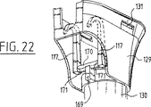
他方、例えば、容器102およびばね117がより可撓ではない材料から作られるときには、図示されているように(図22)撓みばね117の代わりに多様な方向で変形可能である、結合された撓みばねおよびねじりばねを使用することも可能である。このような結合された撓みばねおよびねじりばね117は、図示されている実施態様では、容器102に繋がれている取付金具169、および2つの方向で伸びる、それに垂直に配列されるねじりばね170を備える。実際の撓みばね117は、ねじりばね170の自由な端部に取り付けられ、それ自体曲げられた形状、例えば逆にされたU字形を有する。このようにして、ばね117も、これがより可撓ではない材料から作られるときに、容器102と一体化して成形されてよい。
【0054】
さらに、この実施態様では、事前圧縮システムが、シリンダー110と、シリンダー110に繋がれ、弾性的に可撓隔膜159によって気密および液密で封鎖されていて、環状空間158を備えた噴霧導管109の間に配列されるように図示されている。空間158は、フレーム112内の空洞161の中で受け入れられ、示されている実施態様では隔膜159と一体化して形成されている円筒形のスリーブ160によって界接される。この円筒形のスリーブ160では、その中で可動弁163が配置され、フレーム122内の開口部167を通して流体用の吸込み導管107に繋がれている開口部162が形成される。図示されている実施態様では、開口部167を密封してよいこの弁163も、スリーブ160と一体化して形成される。さらに、隔壁159の曲げを制限するために役立つ抑制装置部材164が、隔膜159に繋がれる。円筒形のスリーブ160は、容器102と一体化して成形される端壁によってフレーム122の空洞161内でロックされる。
【0055】
事前圧縮システム140は、所定のポンプ圧力がまだ達成されていない限り、流体の容器102から吐出しノズルへの輸送を阻止するのに既知の方法で役立つ。流体がノズル108を通して低すぎる圧力で噴霧されると、この流体は不十分に霧化され、噴霧錐体内で生じる滴は大きすぎる。これが発生するのを妨げるために、容器102と吐出しノズル108の間の接続部は、半球形にされた構成により決定され、隔壁159の後ろの周囲圧力により補助される内部応力のために座として役立つ噴霧導管109のリム166に強制的に押し付けられる隔壁159によって封鎖される。例えば約3バールの十分な圧力が、ピストン111をその端部位置へ移動することによりシリンダー110の中で強められるときだけ、隔壁159は座166から持ち上げられるだろう。
【0056】
噴霧器ヘッド101はこのようにして、以下に示すように機能する。ユーザが液体を容器102から噴霧することを希望する場合、ユーザは最初にトリガ113を引く。このようにして、シリンダー110内にあり、弁163により遮断されている開口部167のために容器102の中に逆流できない空気が、ピストン111により圧縮される。空気の圧力がポンプストロークの最後で十分に高いときには、隔壁159は座166から持ち上げられ、空気は逃れてよい。
【0057】
付勢手段116によって強制されるそれ以降の戻りストロークの間、流体は容器102から管123、導管107および開口部162と167を通ってシリンダー110の中に、これが戻りストロークまたは吸込みストローク(図18A)の最後に完全に充填されるまで引き出される。部分的な真空がこのストロークの間に容器102内で作られるのを防止するため、通気穴151がシリンダー110の壁の中に形成され、それは外側周辺密封リップ139Bがピストン111の内向きの移動中に開口部151を通過するときに開かれ、ピストン111の外向きのストロークの間に、ピストン111の外側周囲密封リップと内側周囲密封リップ139Bと139Aの間で画定される、閉じられた空間に再び繋がれる。
【0058】
本発明のこの実施態様に従った噴霧器ヘッド101は、環状のスリーブ160および吸込み管123を射出成形されたフレーム122の中に差し込むことにより組み立てられる。それから、ピストン111はシリンダー110の中に摺動され、トリガ113がそのピボット軸153とフレーム122の中空154の中にパチンと嵌められる。トリガ113およびピストン111がともにパチンと嵌められた、その後、最終的に吐出しノズル108は噴霧導管109の端部に取り付けられてよい。それから、このようにして形成された組立て品は、フレーム122のスナップ部材132が容器102の首部130の上の側材129内の開口部131の中にパチンと嵌るまで容器102の首部の中に導かれるだけでよい。この実施態様は、このようにして第1実施態様より組み立てるのが容易である。
【0059】
容器102および噴霧器ヘッド101を形成し、組み立て、充填する総合的な経路はこのようにして以下のとおりである。最初の場所144では、ポンプ103のシリンダー110、吸込み導管107、および噴霧導管109を載せるフレーム122が射出成形される(図25、ブロック174)。また、トリガ113(ブロック175)、ピストン111(ブロック176)、スリーブ160(ブロック177)、および吐出しノズル108(ブロック178)は、任意の適当な技法、例えば射出成形によって形成される。すべてのこれらのパーツ(部品)はブロック179内で組み立てられる。このように所望される場合、吸込み管123はすでに取り付けられていてよい(ブロック180)。
【0060】
同じ場所で、または違う場所で、そこに統合されている噴霧器ヘッドの一部、前述された実施態様では付勢手段116、だけではなく、容器102も前もって形成される(ブロック181)。それから、多様なパーツ(部品)が、充填動作および最終的な組立て動作が実行される別の場所に輸送される(ブロック182)。
【0061】
すでに組み立てられている(ブロック183)の噴霧器ヘッドの一部には、言うまでもなくこれがすでに過去に実行されていない限り、ステーション185でブロック184から供給される吸込み管123が備えられる。それから、このようにして形成された副組立て品は、緩衝器187を介して位置決めステーション190に供給される。統合された付勢手段116付きの試験管状の予備的形成品146が、ブロック186から充填線路に供給される。すべての追加ステップは、第1実施態様に関して説明され、図22に図示されるステップに一致する。しかしながら、ポンプを容器から引き出される液体で充填することにより、ディスペンサーを「満たす」ことも可能である。この目的のため、ポンプのピストンは、計量配分装置および容器の組立て前に内向きに押されてから、組立て中または組立て後に外向きに引っ張られ、このようにして液体を容器からポンプの中に引き出す。それで、ディスペンサーは使用のための準備が整う。
【0062】
ネジが切ってある首部を有する従来の瓶のためにも使用されてよい本発明の別の実施態様では、噴霧器ヘッドのいくつかのパーツ(部品)が事前に組み立てられるか、あるいは容器の首部とではなく、別個のリング172(図23)と統合される。それから、このリング172は、従来の瓶173(図24)の首部に固定されてよい。このケースでは簡略化された組立て品の優位点がある程度失われるのは真実であるが、噴霧器ヘッドの限られた数のパーツ(部品)に関する優位点は残る。
【0063】
本発明の別の実施態様に従った容器201から液体またはゲルの計量される配分のための装置202は、その吸込み側204が吸込み管205を通して容器201に繋がれるが、その圧力側206が圧力導管207を通して据置き吐出しノズル208に繋がれるポンプ203を備える。示されている実施態様では、計量配分装置202は、ゲル状のハンドソープ向けであり、吐出しノズル208は流出管の形を取る。
【0064】
ポンプ203は、互いに隣接して配列される2つのシリンダー、つまり作業シリンダー209と通気シリンダー210を備える。シリンダー209、210のそれぞれでは、ピストン211,212が変位可能に配列される。通気シリンダー210は、そのストロークの最後でピストン212を変形し、このようにして通気隙間を作り出すためのネジ山236を含む。両方のピストンは、動作手段213によって、このケースでは上向きおよび下向きに可動の推進器部材の形で動作される。この実施態様では、両方のピストンとも、動作部材213にしっかりと繋がれ、動作部材213と一体化して形成される。
【0065】
動作部材213は、休止位置と汲み上げ位置の間で上向き方向と下向き方向で可動である。この汲み上げ位置から、推進器部材が、この実施態様では容器201と一体化して形成されている2つの結合された撓みばねとねじりばね215によっても形成される戻り手段214によりそこから圧力が解放されると、その休止位置に戻される。
【0066】
ポンプ203と吐出しノズル208の間では、事前圧縮システム216も配列される。この事前圧縮システムは、再び、その中には可動遮断弁219も配列されるチェンバー220内で配列されるスリーブ218の一部を形成する隔壁217を備える。スリーブ218は、容器201と一体化して形成されるカップ形をしたパーツ(部品)230の部分を形成する保持器237によってチェンバー220内で固定される。
【0067】
ポンプ203、事前圧縮システムのチェンバー220および吸込みラインと圧力ライン205,207の部分は、カップ形をしたパーツ(部品)230の中に受け入れられる単一の射出成形部品231として形成される。この目的のため、部品223は、カップ形をしたパーツ(部品)230内に配列される長穴233の中に受け入れられる2つの取付け翼部232を有する。このようにして、別個のパーツ(部品)の数は削減され、組立ては簡略化される。また、考えられる漏れという点での問題もこれにより最小限に抑えられる。
【0068】
計量配分装置202は、さらに、それにより装置202の未許可の使用が妨げられてよい、あるいは少なくとも動作の後に検出可能にされてよい阻止手段221を備える。装置202の第1実施態様では、これらの阻止手段は、動作部材213の経路内に配列され、流出管8と一体化して形成されている2つの壊れやすい舌部222によって構成されている。舌部は、それを動作部材の経路の外に持ち出し、それを引き剥がすためにユーザによって操作されてよい掴み部23の上に配列され、それにより推進器部材13は押し下げられ、ポンプ3は動作されてよい。舌部22が使用前に引き剥がされなければならないため、任意の(おそらく未許可の)使用はつねに即座に検出可能となるだろう。
【0069】
動作部材13(図30)と阻止手段21または壊れやすい舌部22を統合することも可能である。その場合、吐出しノズル208は、圧力導管207と一体化して形成されてよく、パーツ(部品)の数はさらに削減されてよい。
【0070】
別の実施態様(図35)では、阻止手段221が、推進器手段213(図37)に枢動可能に繋がれ、吐出しノズルを封鎖し、対応する形状の凹部225内にあるようにするカバー224によって形成され、その結果、推進器部材213は追加移動に対してラッチされる。この実施態様も、噴霧または霧化要素(図36)として実現され、非常に小さい計量オリフィス227を有する円筒形のスリーブ226によって形成される吐出しノズル228と組み合わされてよい。
【0071】
別の実施態様(図44)では、戻り手段214は、内向きに傾いた係合面234を有する4つの撓みばね215を備える。この実施態様の推進器部材213は、ばね215と協働する対応する傾斜面235を有する。推進器部材213が、内向き圧縮ストロークの間押し下げられると、ばね215が下方へ移動する傾斜面235によって内向きに曲げられる。推進器部材213が解放されると、ばね215は撓んで戻り、推進器部材213およびピストン211を再び上方へ移動させる。この実施態様のその他のパーツ(部品)は前記実施態様のパーツ(部品)に対応し、ここではさらに詳細に説明されない。
【0072】
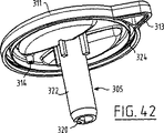
本発明の別の大体実施態様(図38)に従った容器301からの多量の流量の適量に分けられる計量配分のための装置302は、少なくともその側壁306が容器301と一体化して形成される投与チェンバー303を備える。投与チェンバー303内に配列されているのは、投与部材304の下面323に設置され、容器301の底部318近くの位置まで伸びる浸漬管316によって容器の内部と連絡する投与部材304である。投与部材304は、投与チェンバー303の底部として機能する円盤状のパーツ(部品)307に固定される、またはそれと一体化して形成される。この円盤状のパーツ(部品)307は、周辺部に沿って配列され、それが容器301と投与チェンバー303の間の狭められた首部321内で封止状に受け取ることができるスカート308を備える。円盤状のパーツ(部品)307は、さらに、投与チェンバー303内の回転に逆らって円盤状のパーツ(部品)を固定するためなど、投与チェンバー303の中に伸びる長手方向リブ328の回りに配置されることが意図される長手方向溝326を備えられる。第2部材305は、投与部材304の中で回転自在に受け入れられる。この第2部材305は上部で投与チェンバー303を閉じるカバー311に固定される、あるいはカバー311と一体化して経営され、投与チェンバー303を基準にして回転自在である。カバー311は、例えばスナップ接続部324、325によって、投与チェンバー303の壁6に固定できる。
【0073】
投与部材304の円筒形本体309内では、多くの出口開口部310が周囲方向で、さまざまな高さで分散して配列される。同様の円筒形の第2部材305は、その円筒形の壁322の中に隠され、投与部材を基準にしてこの部材305を回転することにより投与部材304の出口開口部310の1つと合わせて設置できる溝320を備えられる。図39および図40に示されている位置では、第2部材305の溝320は、したがって容器301の内部と投与部材303の間に液体の接続がないように、投与部材4の出口開口部310の1つと合っていない。カバー311は、さらにこの位置でカバー311の三角形の突出する部分313が投与チェンバー303の出口開口部または吐出し口312と封止状に協働するように、図示された実施態様では形成される。このようにして、漏れは完全に防止される。カバー311内にさらに配列されるのは、投与装置302の開放された位置で、空気が投与チェンバー303の中に、それが空にされると貫通できることを確実にするが、図示されている閉鎖位置では投与チェンバー303内に突出するリブ328の上部端縁に配列されるカム315によっても閉じられる通気開口314である。
【0074】
したがって、投与装置302の動作は以下のとおりである。図39および図40に図示されている閉鎖位置から開始され、第2部材305付きのカバー311が回転し、投与部材304がその溝326およびリブ328によって回転に逆らって保持されるとき、この第2部材305の溝320は、投与部材304の出口開口部310の内の1つと合わせて設置でき、それにより液体接続が容器301と投与チェンバー303の間に形成される。このような位置に到達することは、投与チェンバー303の外側壁306に配列され、相対位置でカバー311の三角形の閉鎖部分313と正確に合わせてある印317によって示される。容器301がこの位置の中に押し込まれると、液体は投与チェンバー303の底部にある開口部319を介して浸漬管316を通って、投与部材304に運ばれ、それからチャネル320および関連する出口開口部310を介して投与チェンバー303の中に流れ込む。容器301は、ここに、投与チェンバー303の液面がいずれにせよ関連出口開口部310の上にある限り押し込まれなければならない。容器301がそれから解放されると、液体は、そこで優勢となる減圧の結果として、出口開口部310および溝320を介して、浸漬管316に、および最終的には容器301に吸い戻されるだろう。この戻し吸込みは、出口開口部310が液面の下にある限り発生する。投与チェンバー303内の液面が出口開口部310の上部に達すると、空気は引き込まれ、それ以降投与チェンバー303から容器301への液体の流れは停止する。その瞬間、正確に決定された液体の量は、それ以降吐出し口312を通して注ぎ出すことができる、投与チェンバー303内で残されたままとなる。
【0075】
述べられているように、容器301および投与チェンバー303は一体化して形成される。容器301が形成され、液体で充填された後、それ以外の構成部品は、容器301および投与チェンバー303の中に押し込んだり、固定してパチンと嵌めることができ、その後、投与装置302付きの容器301は使用の準備が整う。
【0076】
本発明がその多くの考えられる実施態様を参照して前述されたが、熟練者は、多くの修正をそれに加えることができることを理解するだろう。特に、直接的に容器付き計量配分装置のパーツ(部品)の統合に関係していないディスペンサーの新規の本発明の特徴は、従来の別個に生産されるディスペンサーに同等な効果をもって適用できるだろう。したがって、本発明の範囲は、添付クレームにより完全に定義される。
【図面の簡単な説明】
【図1】 まだ膨らまされておらず、計量配分装置の一部がその上に前もって形成されている容器を長手方向断面で概略して示す図。
【図2】 その中に計量配分装置の残りの部分が配列されている、膨らまされた状態の、図1の容器の詳細による概略長手方向断面図。
【図3】 その閉鎖位置にある計量配分装置の図2に対応する図。
【図4】 計量配分装置の残りの部分に加えて、まだ膨らまされておらず、その上に計量配分装置の一部および取り扱いパーツが前もって形成される、本発明の第2実施態様に従った容器の透視図。
【図5】 膨らまされ、組み立てられた状況での容器およびヘッドの組立て品の透視図。
【図6】 図5の組立て品の平面図。
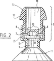
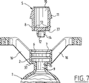
【図7】 その組立ての前の図5の容器およびヘッドの詳細を長手方向断面図。
【図8】 本発明の第2実施態様の図4に対応する図。
【図9】 本発明の第2実施態様の図5に対応する図。
【図10】 本発明の第2実施態様の図6に対応する図。
【図11】 組み立てられた状況での図9の容器およびヘッドの部分的な断面の詳細図。
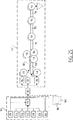
【図12】 本発明に従った方法の異なるステップを概略して示す図。
【図13】 容器の首部分、および本発明の第1実施態様に従って、そこと統合されている付勢手段の透視詳細図。
【図14】 図13の容器、およびそこに繋がれている噴霧器ヘッドの一部の側面立面図。
【図15】 組み立てられた状態での容器および噴霧器ヘッドの図14に対応する図。
【図16】 図14の組立て品の透視図。
【図17】 図14の図に対応するが、部分的に断面図。
【図18】 本発明の好ましい実施態様に従った容器および噴霧器ヘッドの組立て品の透視図。
【図19】 図18の噴霧器ヘッドの透視展開図。
【図20】 ポンプストローク中の組み立てられた状態での図19の噴霧器ヘッドの部分的に断面図。
【図21】 戻りストローク中の噴霧器ヘッドの図20に対応する図。
【図22】 噴霧器ヘッドの偏向手段の代替実施態様の透視図。
【図23】 容器との接続のために、噴霧器ヘッド、固定リングにより構成されている組立て品の代替実施態様の透視図。
【図24】 図23の噴霧器ヘッドおよび固定リング、ならびにそれに繋がれている容器の透視図。
【図25】 本発明に従った方法の多様なステップの概略表記の図。
【図26】 本発明の第1実施態様に従った計量配分装置を有する容器の展開透視図。
【図27】 組み立てられた状態での図26の容器および計量配分装置の透視図。
【図28】 図26および図27の容器および計量配分装置の長手方向断面図。
【図29】 図28の計量配分装置の拡大尺度の詳細図。
【図30】 計量配分装置の代替実施態様の図29に対応する図。
【図31A】 計量配分装置の動作部材の立面図。
【図31B】 計量配分装置の動作部材の透視下面図。
【図32】 計量配分装置のシリンダーポンプの斜視図。
【図32A】 計量配分装置のシリンダーポンプの線A−Aに沿った断面図。
【図32B】 計量配分装置のシリンダーポンプの線B−Bに沿った断面図。
【図33A】 そこに阻止手段が統合されている別個の吐出しノズルの透視図。
【図33B】 そこに阻止手段が統合されている別個の吐出しノズルの透視図。
【図34】 計量配分装置の戻り手段を含む、前もって形成された容器の透視図。
【図34A】 計量配分装置の戻り手段を含む、前もって形成された容器の線A−Aに沿った断面図。
【図34B】 計量配分装置の戻り手段を含む、前もって形成された容器の線B−Bに沿った断面図。
【図35】 計量配分装置のまだ別の実施態様の図26に対応する図。
【図36A】 その計量配分装置で使用される吐出しノズルの長手方向断面図。
【図36B】 その計量配分装置で使用される吐出しノズルの前面図。
【図37】 この計量配分装置の阻止手段を含む、動作部材の透視下面図。
【図38】 本発明に従った計量配分装置付きの容器の展開部分とともに透視平面図。
【図39】 組み立てられた状態での図38の計量配分装置つき容器とともに長手方向断面を示す図。
【図40】 図39の計量配分装置の拡大尺度での詳細図。
【図41】 図38の装置の投与部材の透視下面図。
【図42】 計量配分装置のカバーおよび送り部材の透視下面図。
【図43】 前もって形成された状態での容器および投与チェンバーの透視平面図。
【図44】 本発明の別の実施態様の前もって形成された容器の透視図。
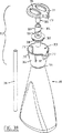
【図45】 図44の容器の予備的形成品、および計量配分装置の一部を形成する動作部材またはキャップの透視断面図。
【図46】 内向きストロークの始まりでの組み立てられた状態での、計量配分装置、および容器の首部の部分断面図。
【図47】 内向きストロークの最後での図46に対応する図。[0001]
(Technical field)
The present invention is connected to a metering container that is divided into an appropriate amount of fluid and has at least one opening. , And opening Collaboration and opening At least one closure member movable between a position for closing the mouth and a position for leaving the opening open , It relates to a metering distribution device provided with. Such a dispensing device is known, for example, in the form of a water bottle or a drinking bottle head.
[0002]
(Background technology)
The term “fluid” , Any non-gas flowing medium Means , Therefore finely dispersed powdered solid material As well as liquid Also means , It is understood.
[0003]
Known dispensing devices are generally releasably connected to a container, for example screwed to the neck of the container after the container has been formed and filled. The dispensing device forming an independent device is generally formed separately or assembled from a number of components.
[0004]
The known dispensing device thus has the disadvantage that it has a relatively large number of components and is relatively difficult both to assemble it (formed and filled). . The manufacture and assembly of the dispensing device represents a particular drawback, which is thereby expensive, time consuming and an increasing number of such bottles are used.
[0005]
For this purpose, the present invention must therefore provide a container dispensing device of the type described above, in which the disadvantages described above do not occur. According to the invention, this is at least a metering device. part The neck of the container In Preformed and the rest of the dispensing device portion Is achieved in that it is connected to it . Total Quantity distribution device part In advance on the neck of the container Already fixed The assembly of the weighing distribution device To Consistent with the installation of the metering device and Less total operation required Is achieved. In addition, the metering device Said Remaining portion It is an independent part (parts) Used as Collection Treated Never , Therefore Its strength and rigidity From the container Conventional metering device because it can be pulled out Than in It can take a lighter and simpler form.
[0006]
Of the dispensing device that is preformed on the neck of the container part Is preferably formed integrally with the neck. In this way, the number of separate components is reduced and assembly is thus simplified. The additional reduction in the number of components ,neck Part Also Obtained when formed integrally with the container.
[0007]
Said Neck In Of pre-formed metering device part For example, a closure member The The position of at least Means for securing and holding one, or a closure member at one of its positions Energizing There may be provided means for doing this. like this Energizing The means may advantageously comprise at least one spring.
[0008]
In another embodiment, the dispensing device further comprises at least one pump arranged between the container and the opening, said pump having a suction side and a compression side, said dispensing device further comprising There are movable means connected to the pump for operation, means connected to the suction side of the pump for supplying fluid from the container, and at least one discharge nozzle connected to the compression side of the pump. The dispensing device thus forms a nebulizer head, as is known, for example, from spray bottles for detergents.
[0009]
A nebulizer head according to the prior art comprises a body fixed and usually threaded to the neck of a container or bottle, in which is placed a manually operable piston pump. In order to operate the pump, the trigger is pivotally connected to the body. The suction side of the pump extends into the bottle for a considerable length, usually close to the bottom, through which a fluid, typically a liquid, is connected to a tube from which it can be drawn out of the bottle. The compression side of the pump is connected through a conduit to the discharge nozzle of the nebulizer head. Typically Energizing A return element, which is a spring, is arranged in the pump to force the piston back to its rest position at the end of the pump stroke. Prior art sprayer heads are usually filled after the bottle is completely filled line so Screwed into the bottle .
[0010]
This conventional atomizer head has a relatively large number of parts (parts) And has the disadvantage that it is relatively difficult to assemble. Thus, both manufacture and assembly of the nebulizer head are expensive and time consuming, and are particularly inconvenient in view of the increasing number of spray bottles being used. In addition, various parts of the sprayer head according to the prior art (parts) Is made from a variety of materials, which raises problems in handling spray bottles and recycling them after they are discarded.
[0011]
The drawbacks mentioned above are now The fountain Atomizer head At least some Is pre-formed with the container and the rest of the sprayer head portion Is attached to it That In fact, the present invention Obeyed Dispensing device or sprayer head Is removed .
[0012]
Preformed with container Of the distribution device Part Advantageously at least of the operating means part With May be . For example, the pump is a piston pump and the pump piston puts it in a rest position Energizing Advantageously, at least one spring when connected to the means for It ’s okay, These pistons Energizing The means is preferably attached to the container. A structurally simple embodiment is then obtained when the spring is a flexure and / or torsion spring.
[0013]
To simplify the assembly of the dispensing device and improve its function, the piston Energizing Means with the operating means of the pump Collaboration Is advantageously adapted for. Therefore ,piston Energizing The means need not extend into the pump or be arranged in the pump. In this way, the conventional piston Energizing Occupied by springs The The space filled with air in the pump is suppressed, thereby improving the pumping action. In addition, the piston Energizing The choice of materials for the means is less important because they do not come into contact with the fluid.
[0014]
In this case Good Preferably, all movements of the movement means piston To obey The operating means is Fixed under tension and compression like For example, a fixie To To be snapped The It is noted that it is connected to the stone.
[0015]
The pump advantageously has a housing to which the operating means are movably linked. An easy-to-assemble dispensing device is then obtained when the operating means comprises a trigger that is pivotably snapped onto the pump housing.
[0016]
In a variant of this embodiment, the pump comprises a working cylinder and a ventilation cylinder arranged adjacent thereto, and the operating means are arranged to displace the pistons in these cylinders synchronously. In that case, the operating means preferably comprises a thruster member, the piston or each piston being formed integrally with the thruster member.
[0017]
According to another aspect of the invention, the weighing device comprises operating means and Collaboration Blocking means, the blocking means may comprise at least one fragile tongue arranged in the path of the operating means, or a cover for blocking the discharge nozzle.
[0018]
In accordance with yet another aspect of the present invention, a metering device includes a pre-compression system arranged between a pump and a discharge nozzle. The Prepared, A pump, a pre-compression system, Connect pump to container and / or discharge nozzle Guidance Tube For some, It is formed integrally.
[0019]
A very simple assembly is the rest of the dispensing device Part is , Or on top of the container neck by snap fitting In Of pre-formed metering device part Connected to Sometimes achieved . In this way both of these portion The connection between them can be triggered quickly and easily with just one movement.
[0020]
In another embodiment of the invention, the container and the fluid connection Little Feeding member having at least one outlet opening And this A dosing member fluidly connected to the feed member and having at least one outlet opening exiting into the dosing chamber And there , Said The delivery member and the dosing member determine different doses For In addition, they are rotatable with respect to each other.
[0021]
This embodiment of the invention constitutes a dispensing cap for a squeeze bottle filled with fluid.
[0022]
By rotating the feeding member and the dosing member, the outlet opening of the dosing member can be aligned with the outlet opening of the feeding member. Then, when the bottle is squeezed, the fluid will be forced upward into the delivery member and thereafter will flow through the delivery member and the outlet opening of the delivery member into the delivery chamber. When the pressure on the squeeze bottle is removed, fluid is sucked out of the dosing member through the outlet opening of the dosing member and the feed member due to the reduced pressure inside the bottle. This return suction of fluid ends at the moment air is drawn. This will be the case when the associated outlet opening of the dosing member exceeds the height of the fluid in the dosing chamber. The selection of the height of the outlet openings that are arranged together thus determines the liquid level that can remain in the dosing chamber after the squeeze bottle is released and then poured out and used.
[0023]
This administration device, which allows the administration of liquids in a simple manner and with relatively great accuracy, is suitable for example for administering food or drugs to animals and measuring the required amount of detergent etc. Divide Can be used for.
[0024]
In a preferred embodiment of the dispensing device, the feeding member and the dispensing member each comprise a substantially cylindrical side wall, thereby improving the sealing of the member tube. Preferably, the feed member has an axial groove concealed in its cylindrical side wall, and the dosing member is spaced apart in both the circumferential direction and the axial traversal. The Multiple outlet openings may be included so that different doses of fluid may be dispensed.
[0025]
Further preferred embodiments of the metering device according to this embodiment of the invention are described in the dependent claims 30 to 37.
[0026]
The dosing chamber and container are preferably preformed by injection moulding, and the container is now advantageously in its final shape after preforming. Blowing Molding (Blow molding) Is done. Of the dosing device part A preformed container, already on it, is obtained in this way, which can be easily stored and transported and can be assembled with a small number of operations to form a safe final product.
[0027]
The present invention further provides a container (of Neck part) When Connected there Be Assembly of the metering device as described above Goods About. Such assembly Goods May be simple, inexpensive to manufacture, have fewer components than usual, and may be relatively light.
[0028]
The present invention is as described above. Na It also relates to a container for use in an assembly. On top of that part Such a container, which is preformed in this way, is compared with a conventional container, which only provides equipment for securing the dispensing device, for example in the form of a screw thread around its neck. Provides the advantages described above in terms of ease of assembly, cost, etc.
[0029]
Finally, the present invention relates to a method for producing a container with a dispensing device and filling with a fluid. Such a method is also generally known. In conventional methods, the container or bottle is usually blow Formed and filled at the first location by molding line To be supplied. The bottle is here provided with fixing means such as threads, usually in the vicinity of the filling opening or its neck. A dispensing device constructed from a relatively large number of different components is assembled at another location, where it is provided with fixing means such as threads. Then this head afterwards, In fully assembled form In the filling line Supplied. Filling line Now, the bottle is filled and then the head is fixed, thus , Example e If In In a bottle Fastened.
[0030]
This known method requires a relatively large number of operations in which the production and filling of the container and the dispensing device are not linked to each other and cannot be integrated, so that the method is therefore time consuming, It has the disadvantage of being expensive. In addition, a complete assembly having a relatively high value compared to the final product is formed at a relatively early stage in a manner already known, and as a result, a relatively high failure at a later stage. Good product costs are incurred. Finally, once they are manufactured, empty containers occupy a relatively large amount of space during transport and storage before they are filled.
[0031]
(Disclosure of the Invention)
For this purpose, the present invention must therefore provide a method of the kind described in which the drawbacks do not occur. This includes the steps of forming the container and the dispensing device part Forming the neck part in advance and the rest of the metering device portion Forming a container, filling the container and there remaining balance of the dispensing device portion Is achieved according to the present invention with a method comprising: In this way, filling line By pre-forming part of the assembly of the dispensing device only in this way, the total number of operations is reduced, so that productivity is increased and costs are reduced.
[0032]
Said Of the dispensing device which is pre-formed on the neck part part Is preferably The neck and Integrated, The neck At the same time formed. The number of components is thus reduced and assembly is thus simplified and accelerated. This is even more true when the neck portion is integrated with the container and formed simultaneously.
[0033]
When a container is preformed by injection molding and inflated to its final shape before its filling, the container before filling Occupation Less space is available, resulting in reduced transportation and storage costs. In addition, the relatively complex form of the distribution device portion Can be formed by injection molding and integrated with the container. The container is then produced here from a thermoplastic material, for example PET, which is elastically deformable, so that container When Integration The components of the dosing head thus made can be realized robustly while the container can be easily inflated.
[0034]
The method that is quick and easy to perform is both portion Both can be connected to each other with only one movement, so the rest of the metering device portion Of the dispensing device which is pre-formed on or on the neck of the container by a snap joint part Obtained when connected to.
[0035]
The container is preferably hanging posture Filled with. In contrast to the conventional method of filling, where the containers are transported and filled in an upright position, the machine used for filling is when different volumes and therefore different heights of the containers have to be processed. This need not be adapted.
[0036]
In an additional preferred embodiment, the rest of the metering device portion Includes a pump having a displacement element movable between a first position and a second position, the displacement element for drawing fluid into the pump, etc. container Is moved to its second position before it is closed and moved to its first position after the container is closed. Thereafter, the dispenser formed by the container with the dispensing device is ready for use.
[0037]
The invention will now be described on the basis of a number of embodiments, in which reference is made to the accompanying drawings.
[0038]
(Best Mode for Carrying Out the Invention)
Of the metering device 3 formed in advance on it part The
[0039]
In the illustrated embodiment, the rest of the metering device 3
[0040]
When the contents of
[0041]
In another embodiment of the
[0042]
As mentioned above, the head 3 is formed in advance on it.
[0043]
The rest of the metering device 3
[0044]
Head 3 Said
[0045]
After traveling through the shock absorber 28 This The
[0046]
Finally, in the following station 30, the filled
[0047]
In another embodiment, the dispensing device is a
[0048]
The
[0049]
Each of the
[0050]
Of the
[0051]
The rest of the atomizer head portion In order to assemble, the
[0052]
In another embodiment of the assembly of the
[0053]
On the other hand, for example, when the
[0054]
Furthermore, in this embodiment, a pre-compression system is connected to the
[0055]
The
[0056]
The
[0057]
Energizing means 116 During subsequent return strokes forced by the fluid from the
[0058]
The
[0059]
The overall path for forming, assembling and filling the
[0060]
Of the nebulizer head integrated there, either at the same place or at different places part In the embodiment described above, Energizing
[0061]
Of the nebulizer head already assembled (block 183) part Of course, a
[0062]
In another embodiment of the present invention, which may also be used for a conventional bottle having a threaded neck, some parts of the sprayer head (parts) Are pre-assembled or integrated with a separate ring 172 (FIG. 23) rather than with the neck of the container. This
[0063]
According to another embodiment of the invention container The
[0064]
The
[0065]
The
[0066]
A
[0067]
[0068]
The
[0069]
It is also possible to integrate the actuating member 13 (FIG. 30) and the blocking means 21 or the
[0070]
In another embodiment (FIG. 35), the blocking means 221 is pivotally connected to the propellant means 213 (FIG. 37) to seal the discharge nozzle so that it is in the correspondingly shaped
[0071]
In another embodiment (FIG. 44), the return means 214 comprises four deflecting
[0072]
A
[0073]
Within the
[0074]
Therefore, the operation of the
[0075]
As stated, the
[0076]
Although the present invention has been described above with reference to many possible embodiments thereof, those skilled in the art will appreciate that many modifications can be made thereto. In particular, the parts of the dispensing device with containers directly (parts) The novel inventive features of the dispenser that are not related to the integration of the present invention could be applied with equal effectiveness to conventional separately produced dispensers. Accordingly, the scope of the invention is completely defined by the appended claims.
[Brief description of the drawings]
[Fig. 1] It has not been inflated yet. part The figure which shows schematically the container in which it has previously formed on it in a longitudinal cross section.
[Figure 2] The rest of the metering device in it portion FIG. 2 is a schematic longitudinal cross-sectional view according to details of the container of FIG. 1 in an inflated state in which are arranged.
FIG. 3 is a view corresponding to FIG. 2 of the metering device in its closed position.
[Figure 4] The rest of the metering device portion In addition, a perspective view of the container according to the second embodiment of the invention, which has not yet been inflated, on which a part of the dispensing device and the handling parts are pre-formed.
FIG. 5 is a perspective view of the container and head assembly in an inflated and assembled condition.
6 is a plan view of the assembly shown in FIG. 5;
7 is a longitudinal cross-sectional view of the details of the container and head of FIG. 5 prior to its assembly.
FIG. 8 is a view corresponding to FIG. 4 of the second embodiment of the present invention.
FIG. 9 is a view corresponding to FIG. 5 of the second embodiment of the present invention.
FIG. 10 is a view corresponding to FIG. 6 of the second embodiment of the present invention.
11 is a partial view of the container and head of FIG. 9 in an assembled condition. Na FIG.
FIG. 12 schematically shows different steps of the method according to the invention.
FIG. 13 shows the neck portion of the container and integrated therewith according to the first embodiment of the present invention. Energizing FIG.
14 shows the container of FIG. 13 and the nebulizer head connected thereto. part Side elevation view.
FIG. 15 is a view corresponding to FIG. 14 of the container and nebulizer head in the assembled state.
16 is a perspective view of the assembly of FIG.
FIG. 17 corresponds to the view of FIG. 14, but is a partial cross-sectional view.
FIG. 18 is a perspective view of a container and nebulizer head assembly according to a preferred embodiment of the present invention.
19 is a perspective developed view of the nebulizer head of FIG. 18. FIG.
20 is a partial cross-sectional view of the nebulizer head of FIG. 19 in an assembled state during the pump stroke.
FIG. 21 is a view corresponding to FIG. 20 of the sprayer head during the return stroke.
FIG. 22 is a perspective view of an alternative embodiment of the deflecting means of the nebulizer head.
FIG. 23 is a perspective view of an alternative embodiment of an assembly consisting of a nebulizer head and a retaining ring for connection with a container.
FIG. 24 is a perspective view of the nebulizer head and retaining ring of FIG. 23 and the container connected thereto.
FIG. 25 is a schematic representation of the various steps of the method according to the invention.
FIG. 26 is an exploded perspective view of a container having a metering device according to the first embodiment of the present invention.
FIG. 27 is a perspective view of the container and metering device of FIG. 26 in an assembled state.
28 is a longitudinal cross-sectional view of the container and metering device of FIGS. 26 and 27. FIG.
29 is a detailed view of an enlarged scale of the metering device of FIG. 28. FIG.
FIG. 30 is a view corresponding to FIG. 29 of an alternative embodiment of the metering device.
FIG. 31A is an elevation view of an operating member of the metering device.
FIG. 31B is a transparent bottom view of the operating member of the metering device.
FIG. 32 is a perspective view of a cylinder pump of the metering device.
FIG. 32A is a cross-sectional view along line AA of the cylinder pump of the metering device.
FIG. 32B is a cross-sectional view along line BB of the cylinder pump of the metering device.
FIG. 33A is a perspective view of a separate discharge nozzle with blocking means integrated therein.
FIG. 33B is a perspective view of a separate discharge nozzle with blocking means integrated therein.
FIG. 34 is a perspective view of a preformed container including the return means of the dispensing device.
34A is a cross-sectional view along line AA of a preformed container including return means of a dispensing device. FIG.
FIG. 34B is a cross-sectional view of the preformed container along line BB including the return means of the dispensing device.
FIG. 35 is a view corresponding to FIG. 26 of yet another embodiment of the metering device.
FIG. 36A is a longitudinal sectional view of a discharge nozzle used in the metering device.
FIG. 36B is a front view of the discharge nozzle used in the metering device.
FIG. 37 is a transparent bottom view of the operating member including the blocking means of the metering device.
FIG. 38 is a perspective plan view together with a developed portion of a container with a metering device according to the present invention.
39 shows a longitudinal section along with the container with the metering device of FIG. 38 in the assembled state.
40 is a detailed view on an enlarged scale of the metering device of FIG. 39. FIG.
41 is a transparent bottom view of the dispensing member of the apparatus of FIG. 38. FIG.
42 is a transparent bottom view of the cover and the feeding member of the metering device. FIG.
FIG. 43 is a perspective plan view of the container and dosing chamber in a pre-formed state.
FIG. 44 is a perspective view of a preformed container of another embodiment of the present invention.
45 is a preliminary of the container of FIG. Formation Goods, and of the distribution device part FIG.
FIG. 46 is a partial cross-sectional view of the dispensing device and the neck of the container in the assembled state at the beginning of the inward stroke.
47 is a view corresponding to FIG. 46 at the end of the inward stroke. FIG.
Claims (29)
当該計量配分装置の少なくとも一部が前記容器の首部分に前もって形成され、計量配分装置の残りの部分がそれに繋がれており、
少なくとも1つの開口部、及び、該開口部と協働し、開口部を閉じる位置と開口部を空けた状態にしておく位置との間で可動である少なくとも1つの閉鎖部材と、
前記容器と前記開口部の間に配置される少なくとも1つのピストンポンプであって、前記ピストンポンプが吸込み側と圧縮側とを有すると共に、計量配分装置の前記残りの部分に一体化されたシリンダとシリンダ内で往復動作するピストンとを含む、ピストンポンプと、
前記ピストンの動作のために当該ピストンに繋がれる可動動作手段と、を備え、
前記ピストンは、前記容器の首部分に前もって形成され当該ピストンを休止位置に付勢するためのピストン付勢手段と繋がれており、
ピストン付勢手段は、前記首部分に前もって形成された少なくとも1つの撓み及び/又は捩りばねを備え、
前記容器から流体を供給するために前記ポンプの吸込み側に繋がれた手段と、
前記ポンプの圧縮側に繋がれた少なくとも1つの吐出しノズルと、
を備えていることを特徴とする、計量配分装置。For metering is divided into an appropriate amount of fluid, a metering device which is connected to the container,
At least a portion of the metering device is pre-formed on the neck portion of the container, the rest of the metering device is connected to it,
At least one opening, and, by cooperating with the opening, and at least one closure member is movable between a position to be in a state spaced position and an opening for closing the opening,
At least one piston pump disposed between the container and the opening, the piston pump having a suction side and a compression side, and a cylinder integrated with the remaining part of the metering device; A piston pump, including a piston that reciprocates in a cylinder;
Movable operation means connected to the piston for the operation of the piston,
The piston is connected to piston biasing means formed in advance on the neck portion of the container and biasing the piston to a rest position;
The piston biasing means comprises at least one deflection and / or torsion spring previously formed in the neck portion,
Means connected to the suction side of the pump for supplying fluid from the container;
At least one discharge nozzle connected to the compression side of the pump;
A metering device, comprising:
当該容器は堅固な首部分を有すると共に、付勢手段が前記首部分に前もって形成されており、
前記付勢手段は、少なくとも1つの撓み及び/又は捩りばねを備え、計量配分装置の前記残りの部分内のポンプのピストンと繋がれるように配置されている、
ことを特徴とする容器。 A container for use in the assembly according to claim 23 ,
The container has a rigid neck portion and a biasing means is pre-formed on the neck portion;
The biasing means comprises at least one deflection and / or torsion spring and is arranged to be connected to the piston of the pump in the remaining part of the dispensing device,
A container characterized by that .
a)前記容器と、その首部分と、前記計量配分装置の前記首部分と一体化される部分とを、射出成形によって同時に前もって形成するステップであって、前記計量配分装置の前記首部分と一体化される部分は、計量配分装置のポンプのピストンと繋がれるための少なくとも1つの撓み及び/又は捩りばねを含む付勢手段を備えている、ステップと;
b)前記ポンプと前記ピストンとを含む、前記計量配分装置(101;202)の残りの部分を形成するステップと;
c)前記前もって形成された容器を最終形態にブロー成形するステップと;
d)前記容器を流体で充填するステップと;
e)前記計量配分装置の残りの部分を前記首部分に前もって形成された部分に繋ぐことによって前記計量配分装置を組み立てるステップであって、前記付勢手段を前記ピストンに繋ぎ、同時に前記容器を閉じることを含む、ステップと;
を備える、ことを特徴とする方法。 A method of manufacturing a container having a neck portion with a metering device connected thereto and filling with a fluid,
a) pre-forming the container, its neck part and the part integrated with the neck part of the metering device simultaneously by injection molding, integrated with the neck part of the metering device The part to be converted comprises a biasing means comprising at least one deflection and / or torsion spring for connection with the piston of the pump of the dispensing device;
b) and a said said pump piston, said metering device (101; a step of forming the remainder of the 202);
c) blow molding the preformed container into a final form;
d) filling the container with a fluid ;
e) assembling the metering device by connecting the remaining part of the metering device to a part previously formed on the neck part, connecting the biasing means to the piston and simultaneously closing the container Including a step ;
It comprises, how you characterized in that.
前記変位可能な要素は、流体をポンプ内に引き込む等のために、容器が閉じられる前に前記第2位置に移動させられ、容器が閉じられた後に前記第1位置に移動させられる、
ことを特徴とする、請求項25から28の何れかに記載の方法。The remaining portion of the metering device includes a pump having a displacement element that is moveable between a first position and a second position,
The displaceable element, for such draw fluid into the pump, the container is allowed to move to the second position before the closed, provoking moved to the first position after the container is closed,
29. A method according to any of claims 25 to 28 , characterized in that
Applications Claiming Priority (11)
| Application Number | Priority Date | Filing Date | Title |
|---|---|---|---|
| NL1010778 | 1998-12-10 | ||
| NL1010778 | 1998-12-10 | ||
| NL1011477A NL1011477C2 (en) | 1999-03-05 | 1999-03-05 | Water bottle container dispenser has at least one closing member coacting with opening and movable between position closing opening and position leaving clear opening |
| NL1011477 | 1999-03-05 | ||
| NL1011479A NL1011479C2 (en) | 1999-03-06 | 1999-03-06 | Water bottle container dispenser has at least one closing member coacting with opening and movable between position closing opening and position leaving clear opening |
| NL1011479 | 1999-03-06 | ||
| NL1011962A NL1011962C2 (en) | 1999-05-04 | 1999-05-04 | Water bottle container dispenser has at least one closing member coacting with opening and movable between position closing opening and position leaving clear opening |
| NL1011962 | 1999-05-04 | ||
| NL1013139 | 1999-09-24 | ||
| NL1013139A NL1013139C2 (en) | 1999-09-24 | 1999-09-24 | Water bottle container dispenser has at least one closing member coacting with opening and movable between position closing opening and position leaving clear opening |
| PCT/NL1999/000760 WO2000033969A2 (en) | 1998-12-10 | 1999-12-10 | Dispensing device for a container and method of manufacturing and filling such a container with dosing and/or filling head |
Publications (3)
| Publication Number | Publication Date |
|---|---|
| JP2002531338A JP2002531338A (en) | 2002-09-24 |
| JP2002531338A5 JP2002531338A5 (en) | 2010-01-21 |
| JP4475815B2 true JP4475815B2 (en) | 2010-06-09 |
Family
ID=27532447
Family Applications (1)
| Application Number | Title | Priority Date | Filing Date |
|---|---|---|---|
| JP2000586454A Expired - Lifetime JP4475815B2 (en) | 1998-12-10 | 1999-12-10 | Dispensing device for containers and method for producing and filling containers with dosing and / or filling heads |
Country Status (20)
| Country | Link |
|---|---|
| EP (1) | EP1144120B1 (en) |
| JP (1) | JP4475815B2 (en) |
| KR (2) | KR20010110302A (en) |
| CN (1) | CN1221442C (en) |
| AT (1) | ATE311945T1 (en) |
| AU (1) | AU1897100A (en) |
| BR (1) | BR9916126A (en) |
| CA (1) | CA2353864C (en) |
| CY (1) | CY1105215T1 (en) |
| CZ (1) | CZ301213B6 (en) |
| DE (1) | DE69928832T2 (en) |
| DK (1) | DK1144120T3 (en) |
| ES (1) | ES2251848T3 (en) |
| HK (1) | HK1041860B (en) |
| HU (1) | HUP0104512A3 (en) |
| MX (1) | MXPA01005891A (en) |
| PL (1) | PL195232B1 (en) |
| SK (1) | SK286584B6 (en) |
| TW (1) | TW442432B (en) |
| WO (1) | WO2000033969A2 (en) |
Families Citing this family (5)
| Publication number | Priority date | Publication date | Assignee | Title |
|---|---|---|---|---|
| JP2006198446A (en) * | 2005-01-17 | 2006-08-03 | Canyon Corp | Trigger type pump dispenser |
| CA2547044C (en) | 2005-05-19 | 2014-08-12 | Gotohti.Com Inc. | Severable piston pump |
| JP5631734B2 (en) * | 2007-04-06 | 2014-11-26 | トランスフオーム・フアーマシユーチカルズ・インコーポレーテツド | System and method for delivering fluid medication |
| ITBS20070068A1 (en) | 2007-05-03 | 2008-11-04 | Guala Dispensing Spa | HEAD OF A FLUID DISPENSE DEVICE, EQUIPPED WITH ELASTIC RETURN MEANS |
| KR101548498B1 (en) * | 2007-05-30 | 2015-09-01 | 글락소 그룹 리미티드 | Fluid dispenser |
Family Cites Families (27)
| Publication number | Priority date | Publication date | Assignee | Title |
|---|---|---|---|---|
| US2418348A (en) * | 1946-03-29 | 1947-04-01 | Hermann Martin | Dispensing valve for squeeze tube containers |
| US2579156A (en) * | 1948-09-21 | 1951-12-18 | Jr George W Parvis | Container closure |
| US3157323A (en) * | 1961-04-12 | 1964-11-17 | Nat Products Co | Valve closure for bottles and the like |
| US3738545A (en) * | 1971-03-12 | 1973-06-12 | Kerr Glass Mfg Corp | Sliding plunger dispensing closure |
| WO1980002516A1 (en) * | 1979-05-21 | 1980-11-27 | Yoshino Kogyosho Co Ltd | Manually-operated liquid spraying device |
| US4457455A (en) * | 1981-10-13 | 1984-07-03 | Philip Meshberg | Collapsible container |
| US4679712A (en) * | 1985-02-25 | 1987-07-14 | Realex Corporation | Orifice cover slide actuator lock for viscous product dispenser |
| IT210199Z2 (en) * | 1987-04-10 | 1988-12-06 | Guala Angelo Spa | DISPENSER OF PASTOUS PRODUCTS IN GENERAL AND OF PASTA TOOTHPASTE IN PARTICULAR, WITH LEVER-OPERATED PUMPING MEMBRANE. |
| GR880100328A (en) * | 1987-05-20 | 1989-02-23 | Colgate Palmolive Co | Dispenser for products in paste form |
| NZ228137A (en) * | 1988-03-30 | 1991-10-25 | Merck & Co Inc | Infinitely variable dose measuring cup for use with squeeze bottle |
| US5158211A (en) * | 1990-08-30 | 1992-10-27 | Philip Meshberg | Fluid dispensing unit retainer |
| DE4029586C1 (en) * | 1990-09-14 | 1991-08-01 | Effem Gmbh, 2810 Verden, De | |
| US5385302A (en) * | 1990-10-25 | 1995-01-31 | Contico | Low cost trigger sprayer |
| US5181635A (en) * | 1991-05-31 | 1993-01-26 | Calmar Inc. | Liquid pump dispenser having a stationary spout |
| US5207359A (en) * | 1992-02-24 | 1993-05-04 | Afa Products, Inc. | Tamper evident cover for sprayer nozzle |
| IT1254482B (en) * | 1992-02-28 | 1995-09-25 | Sar Spa | SPRAY BOTTLE WITH OPERABLE PUMP FOR CRUSHING ITSELF |
| US5337931A (en) * | 1993-05-03 | 1994-08-16 | Kitterman Donald M | Dispenser valve |
| US5467900A (en) * | 1994-03-16 | 1995-11-21 | Afa Products, Inc. | Precompression valve for trigger sprayer |
| FR2721285B1 (en) * | 1994-06-20 | 1996-08-02 | Oreal | Manual precompression pump for spraying a liquid and distribution assembly equipped with such a pump. |
| US5425477A (en) * | 1994-06-29 | 1995-06-20 | Monturas, S.A. | Pump sprayer with stationary discharge |
| JP2892289B2 (en) * | 1994-09-16 | 1999-05-17 | キャニヨン株式会社 | Trigger-type dispenser and one-way valve therefor |
| FR2725247B1 (en) * | 1994-10-03 | 1996-12-20 | Py Daniel C | FLUID PUMP WITHOUT DEAD VOLUME |
| US5560545A (en) * | 1994-10-31 | 1996-10-01 | Calmar Inc. | Dual in-line trigger sprayer |
| GB9422826D0 (en) * | 1994-11-11 | 1995-01-04 | Spraysol Gmbh | Dispenser for liquid products |
| US5779108A (en) * | 1995-06-15 | 1998-07-14 | Calmar Inc. | Pressure venting trigger sprayer |
| US5752626A (en) * | 1995-09-08 | 1998-05-19 | Owens-Illinois Closure Inc. | Simulataneous pump dispenser |
| DE19700607A1 (en) * | 1996-11-19 | 1998-05-20 | Elvira Ahrens | Adjustable dispensing head for pressurised bottle containing weed killer, flower fertiliser, etc. |
-
1999
- 1999-12-10 AT AT99962562T patent/ATE311945T1/en not_active IP Right Cessation
- 1999-12-10 KR KR1020017007209A patent/KR20010110302A/en not_active Application Discontinuation
- 1999-12-10 BR BR9916126-5A patent/BR9916126A/en not_active IP Right Cessation
- 1999-12-10 KR KR1020067027446A patent/KR100896166B1/en not_active IP Right Cessation
- 1999-12-10 EP EP99962562A patent/EP1144120B1/en not_active Expired - Lifetime
- 1999-12-10 TW TW088121836A patent/TW442432B/en not_active IP Right Cessation
- 1999-12-10 DK DK99962562T patent/DK1144120T3/en active
- 1999-12-10 MX MXPA01005891A patent/MXPA01005891A/en active IP Right Grant
- 1999-12-10 SK SK775-2001A patent/SK286584B6/en not_active IP Right Cessation
- 1999-12-10 CA CA002353864A patent/CA2353864C/en not_active Expired - Fee Related
- 1999-12-10 ES ES99962562T patent/ES2251848T3/en not_active Expired - Lifetime
- 1999-12-10 PL PL99349661A patent/PL195232B1/en not_active IP Right Cessation
- 1999-12-10 WO PCT/NL1999/000760 patent/WO2000033969A2/en not_active Application Discontinuation
- 1999-12-10 AU AU18971/00A patent/AU1897100A/en not_active Abandoned
- 1999-12-10 JP JP2000586454A patent/JP4475815B2/en not_active Expired - Lifetime
- 1999-12-10 CZ CZ20012046A patent/CZ301213B6/en not_active IP Right Cessation
- 1999-12-10 CN CNB998142476A patent/CN1221442C/en not_active Expired - Lifetime
- 1999-12-10 DE DE69928832T patent/DE69928832T2/en not_active Expired - Lifetime
- 1999-12-10 HU HU0104512A patent/HUP0104512A3/en unknown
-
2002
- 2002-05-13 HK HK02103570.0A patent/HK1041860B/en not_active IP Right Cessation
-
2006
- 2006-02-08 CY CY20061100175T patent/CY1105215T1/en unknown
Also Published As
| Publication number | Publication date |
|---|---|
| DK1144120T3 (en) | 2006-04-18 |
| CZ20012046A3 (en) | 2001-11-14 |
| CA2353864A1 (en) | 2000-06-15 |
| SK286584B6 (en) | 2009-01-07 |
| PL195232B1 (en) | 2007-08-31 |
| HUP0104512A3 (en) | 2002-04-29 |
| DE69928832D1 (en) | 2006-01-12 |
| HK1041860B (en) | 2006-02-03 |
| KR100896166B1 (en) | 2009-05-11 |
| CZ301213B6 (en) | 2009-12-09 |
| WO2000033969A2 (en) | 2000-06-15 |
| CA2353864C (en) | 2009-10-20 |
| TW442432B (en) | 2001-06-23 |
| ES2251848T3 (en) | 2006-05-01 |
| WO2000033969A3 (en) | 2001-02-08 |
| CN1329560A (en) | 2002-01-02 |
| HUP0104512A2 (en) | 2002-03-28 |
| ATE311945T1 (en) | 2005-12-15 |
| KR20070010087A (en) | 2007-01-19 |
| MXPA01005891A (en) | 2004-04-05 |
| SK7752001A3 (en) | 2002-01-07 |
| AU1897100A (en) | 2000-06-26 |
| KR20010110302A (en) | 2001-12-12 |
| HK1041860A1 (en) | 2002-07-26 |
| WO2000033969A8 (en) | 2001-04-19 |
| CY1105215T1 (en) | 2010-03-03 |
| DE69928832T2 (en) | 2006-08-03 |
| JP2002531338A (en) | 2002-09-24 |
| CN1221442C (en) | 2005-10-05 |
| EP1144120A2 (en) | 2001-10-17 |
| BR9916126A (en) | 2001-09-04 |
| EP1144120B1 (en) | 2005-12-07 |
Similar Documents
| Publication | Publication Date | Title |
|---|---|---|
| US6789303B2 (en) | Liquid dispenser and assembly methods therefor | |
| US6345738B1 (en) | Pump dispenser having body with fill-through conduit | |
| US5271534A (en) | Dispenser package for viscous products | |
| US4457455A (en) | Collapsible container | |
| JP4465292B2 (en) | Liquid packaging and dispensing assembly | |
| MXPA01001126A (en) | Liquid sprayer. | |
| US20130068797A1 (en) | Manual pump type fluid dispenser | |
| US20210031982A1 (en) | Dispensing systems and methods for using the same | |
| US4437588A (en) | Accumulative pressure pump | |
| MX2014000905A (en) | Portable refillable cream dispenser. | |
| US20080011783A1 (en) | Device For Packaging And Delivering A Liquid Product | |
| US6378739B1 (en) | Precompression system for a liquid dispenser | |
| CN104176380A (en) | Unit Comprising A Refillable Bottle And A Source Of Product | |
| US5102018A (en) | Miniature dispenser having a venting groove in the pump housing | |
| JP4475815B2 (en) | Dispensing device for containers and method for producing and filling containers with dosing and / or filling heads | |
| US5743440A (en) | Dispensing assembly including a built-dispensing head retracted inside the body of the container and method for manufacturing the dispensing assembly | |
| US7988021B2 (en) | Sliding-jacket pump | |
| CA2268032C (en) | Fluid pump dispenser | |
| RU2229348C2 (en) | Metering device for reservoir, method for making and filling such reservoir with metering and(or) filling adaptor | |
| US5199167A (en) | Method of manufacture of miniature dispenser | |
| JP2578046Y2 (en) | dispenser | |
| JP2716256B2 (en) | Small dispensing device | |
| CA2088645A1 (en) | Dispenser package for viscous products | |
| JP2003137328A (en) | Liquid discharging apparatus |
Legal Events
| Date | Code | Title | Description |
|---|---|---|---|
| A521 | Request for written amendment filed |
Free format text: JAPANESE INTERMEDIATE CODE: A523 Effective date: 20060907 |
|
| A621 | Written request for application examination |
Free format text: JAPANESE INTERMEDIATE CODE: A621 Effective date: 20060907 |
|
| A131 | Notification of reasons for refusal |
Free format text: JAPANESE INTERMEDIATE CODE: A131 Effective date: 20090526 |
|
| A601 | Written request for extension of time |
Free format text: JAPANESE INTERMEDIATE CODE: A601 Effective date: 20090826 |
|
| A602 | Written permission of extension of time |
Free format text: JAPANESE INTERMEDIATE CODE: A602 Effective date: 20090902 Free format text: JAPANESE INTERMEDIATE CODE: A602 Effective date: 20090902 |
|
| A601 | Written request for extension of time |
Free format text: JAPANESE INTERMEDIATE CODE: A601 Effective date: 20090928 |
|
| A602 | Written permission of extension of time |
Free format text: JAPANESE INTERMEDIATE CODE: A602 Effective date: 20091005 |
|
| A601 | Written request for extension of time |
Free format text: JAPANESE INTERMEDIATE CODE: A601 Effective date: 20091026 |
|
| A602 | Written permission of extension of time |
Free format text: JAPANESE INTERMEDIATE CODE: A602 Effective date: 20091102 |
|
| A524 | Written submission of copy of amendment under article 19 pct |
Free format text: JAPANESE INTERMEDIATE CODE: A524 Effective date: 20091126 |
|
| TRDD | Decision of grant or rejection written | ||
| A01 | Written decision to grant a patent or to grant a registration (utility model) |
Free format text: JAPANESE INTERMEDIATE CODE: A01 Effective date: 20100302 |
|
| A01 | Written decision to grant a patent or to grant a registration (utility model) |
Free format text: JAPANESE INTERMEDIATE CODE: A01 |
|
| A61 | First payment of annual fees (during grant procedure) |
Free format text: JAPANESE INTERMEDIATE CODE: A61 Effective date: 20100309 |
|
| R150 | Certificate of patent or registration of utility model |
Free format text: JAPANESE INTERMEDIATE CODE: R150 |
|
| FPAY | Renewal fee payment (event date is renewal date of database) |
Free format text: PAYMENT UNTIL: 20130319 Year of fee payment: 3 |