EP1144120B1 - Dispensing device for a container and method of manufacturing and filling such a container with dosing and/or filling head - Google Patents
Dispensing device for a container and method of manufacturing and filling such a container with dosing and/or filling head Download PDFInfo
- Publication number
- EP1144120B1 EP1144120B1 EP99962562A EP99962562A EP1144120B1 EP 1144120 B1 EP1144120 B1 EP 1144120B1 EP 99962562 A EP99962562 A EP 99962562A EP 99962562 A EP99962562 A EP 99962562A EP 1144120 B1 EP1144120 B1 EP 1144120B1
- Authority
- EP
- European Patent Office
- Prior art keywords
- dispensing device
- container
- pump
- piston
- preformed
- Prior art date
- Legal status (The legal status is an assumption and is not a legal conclusion. Google has not performed a legal analysis and makes no representation as to the accuracy of the status listed.)
- Expired - Lifetime
Links
Images


Classifications
-
- B—PERFORMING OPERATIONS; TRANSPORTING
- B05—SPRAYING OR ATOMISING IN GENERAL; APPLYING FLUENT MATERIALS TO SURFACES, IN GENERAL
- B05B—SPRAYING APPARATUS; ATOMISING APPARATUS; NOZZLES
- B05B11/00—Single-unit hand-held apparatus in which flow of contents is produced by the muscular force of the operator at the moment of use
-
- G—PHYSICS
- G01—MEASURING; TESTING
- G01F—MEASURING VOLUME, VOLUME FLOW, MASS FLOW OR LIQUID LEVEL; METERING BY VOLUME
- G01F11/00—Apparatus requiring external operation adapted at each repeated and identical operation to measure and separate a predetermined volume of fluid or fluent solid material from a supply or container, without regard to weight, and to deliver it
- G01F11/28—Apparatus requiring external operation adapted at each repeated and identical operation to measure and separate a predetermined volume of fluid or fluent solid material from a supply or container, without regard to weight, and to deliver it with stationary measuring chambers having constant volume during measurement
- G01F11/286—Apparatus requiring external operation adapted at each repeated and identical operation to measure and separate a predetermined volume of fluid or fluent solid material from a supply or container, without regard to weight, and to deliver it with stationary measuring chambers having constant volume during measurement where filling of the measuring chamber is effected by squeezing a supply container that is in fluid connection with the measuring chamber and excess fluid is sucked back from the measuring chamber during relaxation of the supply container
-
- B—PERFORMING OPERATIONS; TRANSPORTING
- B05—SPRAYING OR ATOMISING IN GENERAL; APPLYING FLUENT MATERIALS TO SURFACES, IN GENERAL
- B05B—SPRAYING APPARATUS; ATOMISING APPARATUS; NOZZLES
- B05B11/00—Single-unit hand-held apparatus in which flow of contents is produced by the muscular force of the operator at the moment of use
- B05B11/0005—Components or details
- B05B11/0037—Containers
-
- B—PERFORMING OPERATIONS; TRANSPORTING
- B05—SPRAYING OR ATOMISING IN GENERAL; APPLYING FLUENT MATERIALS TO SURFACES, IN GENERAL
- B05B—SPRAYING APPARATUS; ATOMISING APPARATUS; NOZZLES
- B05B11/00—Single-unit hand-held apparatus in which flow of contents is produced by the muscular force of the operator at the moment of use
- B05B11/0005—Components or details
- B05B11/0097—Means for filling or refilling the sprayer
-
- B—PERFORMING OPERATIONS; TRANSPORTING
- B05—SPRAYING OR ATOMISING IN GENERAL; APPLYING FLUENT MATERIALS TO SURFACES, IN GENERAL
- B05B—SPRAYING APPARATUS; ATOMISING APPARATUS; NOZZLES
- B05B11/00—Single-unit hand-held apparatus in which flow of contents is produced by the muscular force of the operator at the moment of use
- B05B11/01—Single-unit hand-held apparatus in which flow of contents is produced by the muscular force of the operator at the moment of use characterised by the means producing the flow
- B05B11/10—Pump arrangements for transferring the contents from the container to a pump chamber by a sucking effect and forcing the contents out through the dispensing nozzle
- B05B11/1001—Piston pumps
- B05B11/1009—Piston pumps actuated by a lever
- B05B11/1011—Piston pumps actuated by a lever without substantial movement of the nozzle in the direction of the pressure stroke
-
- B—PERFORMING OPERATIONS; TRANSPORTING
- B05—SPRAYING OR ATOMISING IN GENERAL; APPLYING FLUENT MATERIALS TO SURFACES, IN GENERAL
- B05B—SPRAYING APPARATUS; ATOMISING APPARATUS; NOZZLES
- B05B11/00—Single-unit hand-held apparatus in which flow of contents is produced by the muscular force of the operator at the moment of use
- B05B11/01—Single-unit hand-held apparatus in which flow of contents is produced by the muscular force of the operator at the moment of use characterised by the means producing the flow
- B05B11/10—Pump arrangements for transferring the contents from the container to a pump chamber by a sucking effect and forcing the contents out through the dispensing nozzle
- B05B11/1001—Piston pumps
- B05B11/1015—Piston pumps actuated without substantial movement of the nozzle in the direction of the pressure stroke
-
- B—PERFORMING OPERATIONS; TRANSPORTING
- B05—SPRAYING OR ATOMISING IN GENERAL; APPLYING FLUENT MATERIALS TO SURFACES, IN GENERAL
- B05B—SPRAYING APPARATUS; ATOMISING APPARATUS; NOZZLES
- B05B11/00—Single-unit hand-held apparatus in which flow of contents is produced by the muscular force of the operator at the moment of use
- B05B11/01—Single-unit hand-held apparatus in which flow of contents is produced by the muscular force of the operator at the moment of use characterised by the means producing the flow
- B05B11/10—Pump arrangements for transferring the contents from the container to a pump chamber by a sucking effect and forcing the contents out through the dispensing nozzle
- B05B11/1042—Components or details
- B05B11/1064—Pump inlet and outlet valve elements integrally formed of a deformable material
-
- B—PERFORMING OPERATIONS; TRANSPORTING
- B05—SPRAYING OR ATOMISING IN GENERAL; APPLYING FLUENT MATERIALS TO SURFACES, IN GENERAL
- B05B—SPRAYING APPARATUS; ATOMISING APPARATUS; NOZZLES
- B05B11/00—Single-unit hand-held apparatus in which flow of contents is produced by the muscular force of the operator at the moment of use
- B05B11/01—Single-unit hand-held apparatus in which flow of contents is produced by the muscular force of the operator at the moment of use characterised by the means producing the flow
- B05B11/10—Pump arrangements for transferring the contents from the container to a pump chamber by a sucking effect and forcing the contents out through the dispensing nozzle
- B05B11/1042—Components or details
- B05B11/1073—Springs
- B05B11/1074—Springs located outside pump chambers
-
- B—PERFORMING OPERATIONS; TRANSPORTING
- B05—SPRAYING OR ATOMISING IN GENERAL; APPLYING FLUENT MATERIALS TO SURFACES, IN GENERAL
- B05B—SPRAYING APPARATUS; ATOMISING APPARATUS; NOZZLES
- B05B11/00—Single-unit hand-held apparatus in which flow of contents is produced by the muscular force of the operator at the moment of use
- B05B11/01—Single-unit hand-held apparatus in which flow of contents is produced by the muscular force of the operator at the moment of use characterised by the means producing the flow
- B05B11/10—Pump arrangements for transferring the contents from the container to a pump chamber by a sucking effect and forcing the contents out through the dispensing nozzle
- B05B11/1042—Components or details
- B05B11/1073—Springs
- B05B11/1077—Springs characterised by a particular shape or material
-
- B—PERFORMING OPERATIONS; TRANSPORTING
- B65—CONVEYING; PACKING; STORING; HANDLING THIN OR FILAMENTARY MATERIAL
- B65D—CONTAINERS FOR STORAGE OR TRANSPORT OF ARTICLES OR MATERIALS, e.g. BAGS, BARRELS, BOTTLES, BOXES, CANS, CARTONS, CRATES, DRUMS, JARS, TANKS, HOPPERS, FORWARDING CONTAINERS; ACCESSORIES, CLOSURES, OR FITTINGS THEREFOR; PACKAGING ELEMENTS; PACKAGES
- B65D47/00—Closures with filling and discharging, or with discharging, devices
- B65D47/04—Closures with discharging devices other than pumps
- B65D47/20—Closures with discharging devices other than pumps comprising hand-operated members for controlling discharge
- B65D47/24—Closures with discharging devices other than pumps comprising hand-operated members for controlling discharge with poppet valves or lift valves, i.e. valves opening or closing a passageway by a relative motion substantially perpendicular to the plane of the seat
- B65D47/245—Closures with discharging devices other than pumps comprising hand-operated members for controlling discharge with poppet valves or lift valves, i.e. valves opening or closing a passageway by a relative motion substantially perpendicular to the plane of the seat the valve being opened or closed by actuating a stopper-type element
- B65D47/247—Closures with discharging devices other than pumps comprising hand-operated members for controlling discharge with poppet valves or lift valves, i.e. valves opening or closing a passageway by a relative motion substantially perpendicular to the plane of the seat the valve being opened or closed by actuating a stopper-type element moving linearly, i.e. without rotational motion
-
- B—PERFORMING OPERATIONS; TRANSPORTING
- B05—SPRAYING OR ATOMISING IN GENERAL; APPLYING FLUENT MATERIALS TO SURFACES, IN GENERAL
- B05B—SPRAYING APPARATUS; ATOMISING APPARATUS; NOZZLES
- B05B11/00—Single-unit hand-held apparatus in which flow of contents is produced by the muscular force of the operator at the moment of use
- B05B11/0005—Components or details
- B05B11/0008—Sealing or attachment arrangements between sprayer and container
Landscapes
- Physics & Mathematics (AREA)
- Fluid Mechanics (AREA)
- General Physics & Mathematics (AREA)
- Engineering & Computer Science (AREA)
- Mechanical Engineering (AREA)
- Containers And Packaging Bodies Having A Special Means To Remove Contents (AREA)
- Basic Packing Technique (AREA)
- Filling Of Jars Or Cans And Processes For Cleaning And Sealing Jars (AREA)
- Details Of Rigid Or Semi-Rigid Containers (AREA)
- Closures For Containers (AREA)
- Supplying Of Containers To The Packaging Station (AREA)
Abstract
Description
- The invention relates to a dispensing device to be connected to a container for dosed dispensing of a fluid, at least a part of the dispensing device being preformed on a neck part of the container and the remaining part of the dispensing device being connected thereto, said dispensing device comprising:
- at least one opening and at least one closing member co-acting with the opening and movable between a position closing the opening and a position leaving clear the opening;
- at least one pump arranged between the container and the opening, the pump having a suction side and a compression side and including a cylinder integrated in the remaining part of the dispensing device and a piston reciprocating therein;
- moveable operating means connected to the piston for operating thereof,
- the piston being connected with biasing means preformed on the neck part of the container and connected with the piston for biasing it to a position of rest;
- means connected to the suction side of the pump for supplying fluid from the container; and
- at least one discharge nozzle connected to the compression side of the pump.
- Such a dispensing device is known from US-A-5,746,728. This prior art document discloses a pump for delivering fluid, in particular a sterile fluid from an elastic phial. The pump includes a pump body that is contained in an end part of the phial near the outlet orifice thereof, and a movable piston that is fitted inside the pump body. The end part of the phial is shaped as a concertina. The piston includes an annular operating part that is accommodated in a fold of the concertina-shaped end part.
- When the pump is operated by moving the piston, the concertina is deformed and due to the elastic nature of the phial acts as a return spring, forcing the piston back to its original position of rest. This particular arrangement of the pump within the phial is said to lead to a remarkable reduction of the number of pieces of the pump. However, it is very much specific to the intended field of use - i.e. high-end flexible containers holding expensive sterilized pharmaceutical substances and suspended with their outlet orifice at the bottom - and can hardly be adapted to low-cost dispensers for consumer products like e.g. detergents.
- The term "fluid" is understood in this text to mean any non-gaseous flowing medium, therefore liquids as well as finely distributed, powdery solid materials.
- A well-known example of a conventional dispensing device of the type described above is a sprayer head for a so called trigger sprayer, which is used for instance for detergents.
- Such a conventional sprayer head comprises a body that may be fixed, usually screwed onto the neck of a container or bottle and in which a manually operable piston pump is arranged. For operating the pump a trigger is hingedly connected to the body. The suction side of the pump is connected to a tube that extends into the bottle over a substantial length, usually to a position near the bottom, and through which a fluid, typically a liquid may be drawn out of the bottle. The compression side of the pump is connected to a discharge nozzle of the sprayer head through a conduit. A return element, typically a biasing spring is arranged in the pump so as to force the piston back to its position of rest at the end of a pump stroke. The conventional sprayer head is usually screwed onto the bottle in the filling line, after the bottle has been completely filled.
- This conventional sprayer head has the drawback of having a relatively high number of parts and being relatively hard to assemble. Thus both manufacture and assembly of the sprayer head are costly and time-consuming, which is especially inconvenient in view of the increasing number of spray bottles being used.
- Furthermore, the various parts of conventional sprayer heads are made of different materials, which poses a problem in handling and recycling the spray bottle after it has been discarded.
- The invention has for its object to provide an improved dispensing device, which is easy to manufacture and assemble, which has a limited number of parts, which moreover may be made from the same or corresponding materials, and which is suitable for household use. In accordance with the invention, this is accomplished in a dispensing device having the features defined above, in that the neck part of the container is stiff and in that the piston biasing means comprise at least one flexion and/or torsion spring preformed on said neck part
- Already fixing a part of the dispensing device beforehand to a neck part of the container achieves that the assembly of the dispensing device in fact coincides with mounting of the dispensing device on the container, whereby in all fewer operations are required. In addition, the remaining part of the dispensing device can take a lighter and simpler form than in conventional dispensing devices, since it will not be used or handled as an independent part and can thus derive its strength and rigidity from the container. The stiff container neck allows easy handling of the container during filling and assembly, while a flexion and/or torsion spring is a structurally simple and effective type of spring.
- In order to simplify assembling of the dispensing device and improve its functioning the piston biasing means are advantageously adapted for cooperation with the operating means of the pump. In that manner the piston biasing means need not extend into or be arranged in the pump. Thus the air filled space within the pump occupied by conventional piston biasing springs is suppressed, whereby the pumping action is improved. Furthermore, the choice of materials for the piston biasing means is less critical, as these will not be in contact with the fluid.
- An effective biasing action is achieved when the piston biasing means include a plurality of substantially parallel springs that engage the operating means.
- In one embodiment of the dispensing device of the invention the springs extend substantially perpendicular to a longitudinal axis of the container, each spring having a closed contour surrounding the pump and being fixed on one end to a column that is attached to said neck part.
- In an alternative embodiment of the inventive dispensing device the springs are separately arranged on opposite sides of the pump and extend substantially parallel to a longitudinal axis of the container. An optimum balance between spring force and structural simplicity is then achieved when the springs are combined flexion and torsion springs having a free end that is shaped in a curve.
- It is noted that in these case the operating means are preferably connected to the piston such as to be fixed under tension and compression, for instance snapped onto the piston, in order to have it follow all movements of the operating means.
- The pump advantageously has a housing to which the operating means are movably connected. An easy to assemble dispensing device is then obtained when the operating means comprise a trigger hingedly snapped onto the pump housing.
- In a variant of this embodiment, the pump comprises a work cylinder and a vent cylinder arranged next thereto and the operating means are arranged for displacing the pistons in these cylinders in synchronized fashion. In that case the operating means preferably comprise a pusher member and the or each piston is integrally formed with the pusher member.
- In order to prevent or detect unauthorized use of the dispensing device, the device may be provided with blocking means cooperating with the operating means, the blocking means comprising at least one frangible tongue arranged in a path of the operating means. In order to reduce the number of separate pieces, the or each frangible tongue may be connected with the discharge nozzle. In an alternative embodiment, the blocking means may comprise a cover closing off the discharge nozzle.
- In order to prevent fluid from being dispensed at too low a pressure, which might lead to insufficient atomizing, the dispensing device may be provided with a precompression system arranged between the pump and the discharge nozzle. In that case, it is preferred that the pump, a part of the precompression system and part of the conduits connecting the pump to the container and/or the discharge nozzle are integrally formed so as to arrive at a maximum reduction of the number of parts while retaining an easy to mold shape. The remaining part of the precompression system is preferably preformed on the neck part of the container.
- A very simple assembly is achieved when the remaining part of the dispensing device is connected by means of a snap coupling to the neck part of the container or to the part of the dispensing device preformed thereon. In this manner the connection between both these parts can be brought about quickly and simply in a single movement.
- The container and the part of the dispensing device preformed therewith are preferably preformed by means of injection molding. This is a simple and well-known technique, allowing relatively complex shapes to be produced swiftly and at low cost. The container is advantageously blow molded to an end form after the preforming. A preformed container with a part of the dosing device already thereon is thus obtained, which can be stored and transported easily and can moreover be assembled with a small number of operations to form a complete end product.
- The invention further relates to an assembly of a neck part of a container and a dispensing device as described above connected thereto. Such an assembly is simple and can be manufactured at low cost, has fewer components than usual and can in addition be relatively light.
- The invention also relates to a container for use in an assembly as described above. In accordance with the invention such a container has a neck part that is stiff and biasing means preformed on said neck part, said biasing means comprising at least one flexion and/or torsion spring and being arranged to be connected with a piston of a pump in the remaining part of the dispensing device. This container provides the above discussed advantages in respect of ease of assembly, cost price and the like when compared to conventional containers, which are provided only with provisions for fixing a dispensing device, for instance in the form of screw thread round their neck.
- Finally, the invention relates to a method of manufacturing and filling with a fluid a container having a neck part with a dispensing device connected thereto. Such methods are generally known.
- In the conventional method the container or bottle is formed at a first location, generally by means of blow molding, and supplied to a filling line. The bottle is herein usually provided with fixing means such as screw thread in the vicinity of the filling opening or neck thereof. The dispensing device, which is constructed from a relatively large number of different components, is assembled at another location and herein also provided with fixing means such as screw thread. This head is then supplied in fully assembled form to the filling line. On the filling line the bottle is filled, whereafter the head is fixed, thus for instance screwed, thereon.
- This known method has the drawback that the manufacturing and filling of the container and dispensing device require a relatively large number of operations, which are not geared to each other and cannot be integrated either, whereby the method is therefore time-consuming and expensive. In addition, complete assemblies are already formed at a relatively early stage in the known method which have a relatively high value compared to the end product, which results in the cost of possible rejects at a later stage being relatively high. Finally, once they have been manufactured the empty containers take up a relatively large amount of space during transport and storage before they are filled.
- In e.g. US-A-5,337,931, which is directed at a plastic dispensing container having a dispensing valve that is partially integrated in the neck part of the container, it is implicitly disclosed that such a container may be manufactured and filled by first injection moulding the container and its integrated part of the dispensing valve, further forming the remaining part of the dispensing valve, then filling the container and finally assembling the dispensing valve by connecting the remaining part with the part that is integrated in the neck of the container. In that case however, the dispensing device is a simple valve, rather than a pump.
- Moreover, from e.g. EP-A-0 372 671 it is known that a container may be manufactured by first injection moulding a test tube like preform, and then blow moulding this preform into the final container form.
- The invention now has for its object to provide a method of the described type, wherein said drawbacks do not occur. This is achieved according to the invention with a method which comprises the steps of:
- a) simultaneously preforming, by injection moulding, the container, its neck part and a part of the dispensing device that is integral with said neck part, said part of the dispensing device that is integral with said neck part comprising biasing means including at least one flexion and/or torsion spring for connection with a piston of a pump of the dispensing device;
- b) forming the remaining part of the dispensing device including the pump and the piston;
- c) blow moulding the preformed container into its final form;
- d) filling the container with the fluid; and
- e) assembling the dispensing device by connecting the remaining part thereof with the part preformed on the neck part, including connecting the biasing means to the piston thus simultaneously closing the container.
-
- By performing in this manner a part of the assembly of the dispensing device only on the filling line, the total number of operations is reduced, which results in an increase in productivity and a decrease in costs. Forming the various parts integrally and simultaneously leads to the number of components being reduced and assembly thus simplified and accelerated. Since the container is preformed by means of injection molding and is blow molded into its final form before filling thereof, the space occupied by the containers prior to filling is reduced, which results in a decrease in the cost of transport and storage.
- The container is advantageously manufactured from a resiliently deformable thermoplastic material, for instance PET, so that the components of the dosing head integrated therewith can be embodied robustly while the container can be blow molded simply.
- A method which is quick and easy to perform is obtained when the remaining part of the dispensing device is connected by means of a snap coupling to the neck part of the container or the part of the dispensing device preformed thereon, since both parts can then be mutually connected in a single movement.
- The container is preferably filled in suspended position. In contrast to the conventional method of filling, wherein the containers are transported and filled in standing position, a machine used for filling does not hereby have to be adapted when containers with a different volume and thus a different height have to be processed.
- In a further preferred embodiment, the remaining part of the dispensing device includes a pump having a displacement element that is moveable between first and second positions, the displaceable element being moved to its second position before the container is closed and being moved to its first position after the container is closed, such as to draw fluid into the pump. The dispenser, formed by the container with its dispensing device is then ready for use.
- The invention will now be elucidated on the basis of a number of embodiments, wherein reference is made to the annexed drawing, in which:
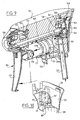
- Figure 1 is a perspective detailed view of the neck of a container and biasing means integrated therewith according to a first embodiment of the invention,
- Figure 2 is a side elevation of the container of Figure 1 and part of a sprayer head connected therewith,
- Figure 3 is a view corresponding to Figure 2 of the container and sprayer head in assembled state,
- Figure 4 is perspective view of the assembly of Figure 2,
- Figure 5 is a view corresponding to that of Figure 4, but partly in section,
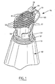
- Figure 6 is a perspective view of an assembly of a container and a sprayer head in accordance with a preferred embodiment of the invention,
- Figure 7 is a perspective exploded view of the sprayer head of Figure 6,
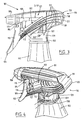
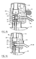
- Figure 8 is a view, partly in section of the sprayer head of Figure 7 in assembled state during a pump stroke,
- Figure 9 is a view corresponding with Figure 8 of the sprayer head during the return stroke,
- Figure 10 is a perspective view of an alternative embodiment of the biasing means of the sprayer head,
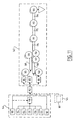
- Figure 11 is a schematic representation of the various steps of the method in accordance with the invention,
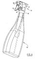
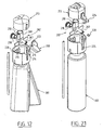
- Figure 12 is an exploded perspective view of a container having a dispensing device in accordance with an alternative embodiment of the invention,
- Figure 13 is a perspective view of the container and dispensing device of Figure 12 in assembled state,
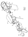
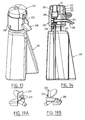
- Figure 14 is a longitudinal sectional view of the container and dispensing device of Figures 12 and 13,
- Figure 15 is an enlarged scale detailed view of the dispensing device of Figure 14,
- Figure 16 is a view corresponding to Figure 15 of an alternative embodiment of the dispensing device,
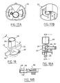
- Figure 17A and 17B show an elevational and a perspective bottom view, respectively, of the operating member of the dispensing device,
- Figure 18, 18A and 18B show a perspective view and sectional views along the lines A-A and B-B, respectively, of the two cylinder pump of the dispensing device,
- Figure 19A and 19B are perspective views of a separate discharge nozzle having blocking means integrated therein,
- Figure 20, 20A and 20B show a perspective view and sectional views along the lines A-A and B-B, respectively, of the preformed container including return means of the dispensing device,
- Figure 21 is a view corresponding with Figure 12 of yet another embodiment of the dispensing device,
- Figure 22A and 22B show a longitudinal sectional view and a front view, respectively, of the discharge nozzle used in that dispensing device,
- Figure 23 is a perspective bottom view of the operating member including blocking means of this dispensing device,
- Figure 24 is a perspective view of the preformed container of yet another embodiment of the invention,
- Figure 25 is a perspective sectional view of the container preform of Figure 24 and an operating member or cap that forms part of the dispensing device,
- Figure 26 is a partial sectional view of the dispensing device and neck of the container in assembled state at the beginning of an inward stroke, and
- Figure 27 is a view corresponding to Figure 26 at the end of the inward stroke.
-
- In a first embodiment the dispensing device is a
sprayer head 101 for a container 102 (Figure 2) comprising apump 103 having asuction side 105 and acompression side 106. Movable operating means 104 are connected to thepump 103, in the illustrated example constituted by atrigger 113 having ahook part 115 snapped around apivot shaft 114.Means 107 are connected to thesuction side 105 of thepump 103 for supplying a fluid from the container, comprised of a conduit having its free end connected to atube 123 extending into the container. Thecompression side 106 of thepump 103 is connected to adischarge nozzle 108 through aconduit 109. In the illustratedembodiment pump 103, operating means 104 anddischarge nozzle 108 are arranged in aframe 122, which can be fixed to thecontainer 102 in a way to be discussed below. -
Pump 103 is a piston pump, constituted by a pump housing orcylinder 110 and apiston 111 reciprocating therein. Thepiston 111 is connected to apiston rod 112 which in turn is connected to thetrigger 113. In order to return thepiston 111 and trigger 113 to their extended position of rest at the end of a pump stroke, thesprayer head 101 comprises biasing means 116. - In the illustrated embodiment the biasing means are constituted by a plurality of parallel flexion springs 117 that engage the
trigger 113. When thetrigger 113 is pivoted around thepivot shaft 114 towards thepump 103 and presses thepiston 111 into thecylinder 110 during a pump stroke, thesprings 117 are bent. When the pressure on thetrigger 113 is released it is forced back to its position of rest by thesprings 117 flexing back. Since the trigger is connected to thepiston 111 such as to remain fixed under both tension and compression, thepiston 111 is then also pulled back to its position of rest. The connection between thetrigger 113 and thepiston 111 is formed by thepiston rod 112, which is snapped onto thepiston 111 and is connected to thetrigger 113 by means of a film hinge. The snap connection between thepiston rod 112 and thepiston 111 is formed by ahead 127 of thepiston rod 112 being snapped into acorresponding opening 128 in thepiston 111. - The
springs 117 each have a closed contour and are fixed on oneend 118 to a column or "spine" 119 whereas the opposite side of eachspring 117 has aprotrusion 124 engaging in acavity 125 in thetrigger 113. Thecolumn 119 which consists of acurved web 120 and a reinforcing rib arranged therein, has a partlycylindrical basis 129 which is attached to theneck 130 of thecontainer 102. Thebasis 129, thecolumn 119 and thesprings 117 are integrally molded with thecontainer 102. In thebasis 129 twoopposite openings 131 are arranged which cooperate with two protrudingsnap members 132 on theframe 122 carrying thepump 103, the operating means 104 and thedischarge nozzle 108. Thisframe 122 further comprises a cylindrical lower part or skirt 133 which may be close fittingly received in theneck 130 of thecontainer 102 an there constitutes a gas-and liquid tight seal with theinner edge 134 of that neck. Theframe 122 further comprises anedge 135 and ashoulder 143 which in the assembled state of thesprayer head 101 come to rest on the upper edge 136 of theneck 130. - Since part of the
sprayer head 101, in the shown embodiment the biassing means 116 form part of thecontainer 102, assembling thesprayer head 101 finally takes place on the moment that thecontainer 102 is filled and subsequently closed by placing theframe 122 carrying the various parts of thesprayer head 101. Since part of the operations relating to assembly of thesprayer head 101 are in fact integrated with the final assembly which are also necessary, the total number of operations to be performed for forming the container with the sprayer head is substantially lower than with conventional, completely pre-assembled sprayer heads. - Furthermore, the number of sperate parts is substantially reduced in comparison to a conventional sprayer head, since certain parts are integrated in the container.
- For assembling the remaining parts of the sprayer head the flexion springs 117 must be introduced into the
cavity 125 of thetrigger 113. To this end thepiston 111 must be moved to its outer position. Then the remaining part of thesprayer head 101 may be pressed into the neck of thecontainer 102 and fixed therein by means of thesnap members 132 engaging in theopenings 131. - In another embodiment of the assembly of
sprayer head 101 andcontainer 102, which is the preferred embodiment at the moment (Figure 6), the biasing means 116 take the shape of separate flexion springs 117 extending substantially parallel to the longitudinal of axis of thecontainer 102, instead of perpendicular thereto as in the first embodiment. These flexion springs 117 cooperate withribs 152 arranged in thecavity 125 of thetrigger 113. In this embodiment thetrigger 113 has acontinuous pivot shaft 153 that is received in ahollow space 154 in theframe 122 and that is locked therein by aflexible snap arm 155. As theshaft 153 of thetrigger 113 and the receivingspace 154 are located above the sprayingconduit 109, anaperture 156 is arranged in thetrigger 113, through which extends the end of thisconduit 109, onto which is arranged thedischarge nozzle 108. The trigger further comprises protruding cams (not shown here) which directly engage inopenings 128 of thepiston 111. This embodiment therefore has no separate piston rod. - On the other hand it is also possible, for instance when the
container 102 and thesprings 117 are made of a material that is less flexible, to use combined flexion and torsion springs that are deformable in various directions instead of the flexion springs 117 as shown (Figure 10). Such combined flexion and torsion springs 117 comprise in the shown embodiment abracket 169 connected to thecontainer 102 and atorsion spring 170 arranged perpendicular thereto, which extends in two directions. The actual flexion springs 117 are attached to the free ends 171 of thetorsion spring 170 and have a curved shape in themselves, for instance an inverted Ushape. In this way thesprings 117 may also be molded integrally with thecontainer 102 when this is made of a less flexible material. - Furthermore, in this embodiment a precompression system is shown to be arranged between the
cylinder 110 and the sprayingconduit 109 comprising anannular space 158 connected to thecylinder 110 and closed off in a gas-and liquid-tight manner by a resilientlyflexible diaphragm 159. Thespace 158 is bordered by acylindrical sleeve 160 that is received in acavity 161 in theframe 122 and that is integrally formed with thediaphragm 159 in the illustrated embodiment. In thiscylindrical sleeve 160 anopening 162 is formed, in which is arranged amovable valve 163, and which is connected to thesuction conduit 107 for the fluid through an opening 167 in theframe 122. In the shown embodiment thisvalve 163, which may hermetically seal the opening 167, is also integrally formed with thesleeve 160. Further astop member 164 is connected to thediaphragm 159, which serves to limit bending of thediaphragm 159. Thecylindrical sleeve 160 is locked in thecavity 161 of theframe 122 by an end wall which is integrally molded with thecontainer 102. - The
precompression system 140 serves in known manner to inhibit transport of fluid from thecontainer 102 to the discharge nozzle as long as a predetermined pump pressure is not yet attained. If a fluid is sprayed through thenozzle 108 at too low a pressure, this fluid is insufficiently atomized and drops generated in the spray cone are too large. In order to prevent this from occurring the connection between thecontainer 102 and thedischarge nozzle 108 is closed off by thediaphragm 159 which is forcibly pressed against therim 166 of the sprayingconduit 109 serving as a seat due to the internal stress determined by the domed configuration and assisted by the ambient pressure behind thediaphragm 159. Only when sufficient pressure, for instance on the order of 3 bar, is built up in thecylinder 110 by moving thepiston 111 to its end position will thediaphragm 159 be lifted from theseat 166. - The
sprayer head 101 thus functions as follows. When a user wishes to atomize the fluid from thecontainer 102, he first pulls thetrigger 113. In this way air that is present in thecylinder 110 and that cannot flow back to thecontainer 102 due to the opening 167 being shut off by thevalve 163 is compressed by thepiston 111. When the pressure of the air is high enough at the end of the pump stroke thediaphragm 159 is lifted from theseat 166 and the air may escape. - During the subsequent return stroke forced by the biasing means 116 fluid is drawn from the
container 102 throughtube 123,conduit 107 andopenings 162 and 167 into thecylinder 110 until this is completely filled at the end of the return or suction stroke (Figure 9). - In order to prevent a partial vacuum from being developed in the
container 102 during this stroke anaeration hole 151 is formed in the wall of thecylinder 110, which is opened when an outer peripheral sealing lip 139B passes theopening 151 during inward movement of thepiston 111 and which is again connected to a closed space defined between the outer and inner peripheral sealinglips 139B and 139A of thepiston 111 during the outward stroke of thepiston 111. - The
sprayer head 101 in accordance with this embodiment of the invention is assembled by inserting theannular sleeve 160 and thesuction tube 123 into the injection moldedframe 122. Then thepiston 111 is slid into thecylinder 110 and thetrigger 113 is snapped with itspivot shaft 153 into the hollow 154 of theframe 122. After that thetrigger 113 and thepiston 111 are snapped together, after which finally thedischarge nozzle 108 may be attached to the end of the sprayingconduit 109. The assembly thus formed may then simply be introduced into the neck of thecontainer 102 until thesnap member 132 of theframe 122 snap into theopenings 131 in thecheeks 129 above theneck 130 of thecontainer 102. This embodiment is thus easier to assemble than the first embodiment. - The total path of forming, assembling and filling the
container 102 and thesprayer head 101 is thus as follows. At afirst location 144 theframe 122 carrying thecylinder 110 of thepump 103, thesuction conduit 107 and the sprayingconduit 109 is injection molded (Figure 11, block 174). Also the trigger 113 (block 175), piston 111 (block 176), sleeve 160 (block 177) and discharge nozzle 108 (block 178) are formed by any suitable technique, for instance injection molding. All these parts are assembled inblock 179. If so desired also thesuction tube 123 may already be mounted (block 180). - At the same location or a different location the
container 102 is preformed (block 181), as well as the part of the sprayer head integrated therewith, in the embodiment illustrated above the biasing means 116. The various parts are then transported (block 182) to a different location, where the filling and final assembly operations are performed. - The part of the sprayer head that has already been assembled (block 183) is provided with a
suction tube 123 supplied from ablock 184 at astation 185, unless of course this had already been done previously. Then the thus formed subassembly is supplied to apositioning station 189 via a buffer 187. The test-tube likepreform 146 with integrated biasing means 116 is supplied to a filling line from ablock 186. At afirst station 148 of this filling line thepreform 146 is heated and then inflated to form acontainer 102 with the desired final shape. For this purpose preform 146 has a handling edge on which it can be picked up and clamped. This is therefore a two-stage process for blow molding ofcontainer 102. It is however also possible to form the container in a one-stage process, wherein in one and thesame machine preform 146 is injection molded and, while still warm, inflated to its final form. - After progressing through a
buffer 188 the thus formedcontainer 102 is then filled in asubsequent station 149 with a fluid, generally a liquid, for instance a liquid cleaning product or the like. The presence of the handling edge is an advantage herein, sincecontainer 102 can be suspended therefrom in the filling machine. In contrast to conventional filling stations, in whichcontainer 102 is transported in standing position, this fillingstation 149 does not therefore have to be adapted when containers of a different volume, and thus a different height, have to be processed. - Finally, in a following
station 150 the filledcontainer 102 is closed by arranging thereon the remaining part of dispensing device, i.e. the sprayer head subassembly. The thus formed assembly then progresses further through the usual steps of labelling (block 191), packing into boxes (block 192) and palletizing and shrink-wrapping (block 193), wherein theusual buffers - However, it is also possible to "prime" the dispenser, by filling the pump with some liquid drawn from the container. To this end the piston of the pump is pushed inward before assembly of the dispensing device and the container, and is then pulled outward during or after assembly, thus drawing liquid from the container into the pump. The dispenser is then ready for use.
- A
device 202 for metered dispensing of a liquid or gel from acontainer 201 in accordance with yet another embodiment of the invention (Figure 12) comprises apump 203, asuction side 204 of which is connected to thecontainer 201 through asuction conduit 205, whereas thepressure side 206 thereof is connected to astationary discharge nozzle 208 through apressure conduit 207. In the illustrated embodiment thedispensing device 202 is meant for a gel like hand soap and thedischarge nozzle 208 takes the form of an outflow tube. - The
pump 203 comprises two cylinders arranged next to each other, awork cylinder 209 and avent cylinder 210. In each of the cylinders 209,210 a piston 211,212 is displaceably arranged. Thevent cylinder 210 includes aridge 236 for deforming thepiston 212 at the end of its stroke, thus creating a venting gap. Both pistons are operated by operating means 213, in this case in the shape of an upwardly and downwardly moveable pusher member. In this embodiment both pistons are rigidly connected to, and even integrally formed with the operatingmember 213. - The operating
member 213 is moveable in upward and downward direction between a position of rest and a pumping position. From this pumping position the pusher member is returned to its position of rest when the pressure is released therefrom by return means 214, which in this embodiment are also formed by two combined flexion and torsion springs 215 that are integrally formed with thecontainer 201. - Between the
pump 203 and the discharge nozzle 208 aprecompression system 216 is also arranged. This precompression system again comprises adiaphragm 217 which forms part of asleeve 218 arranged in achamber 220, in which is also arranged a moveable shut-offvalve 219. Thesleeve 218 is fixed in thechamber 220 by aretainer 237 forming part of a cup-shapedpart 230 that is integrally formed with thecontainer 201. - The
pump 203, thechamber 220 of the precompression system and part of the suction andpressure lines piece 231, that is received in the cup-shapedpart 230. To this end thepiece 231 has two mountingwings 232 which are received inslots 233 arranged in the cup shapedpart 230. In this way, the number of separate parts is reduced and the assembly is simplified. Also problems in respect of possible leakage are hereby minimized. - The
dispensing device 202 further comprises blocking means 221 by which unauthorized use ofdevice 202 may be prevented or at least rendered detectable after the act. In a first embodiment of thedevice 202 these blocking means are constituted by twofrangible tongues 222 that are arranged in the path of the operatingmember 213 and that are integrally formed with thedischarge nozzle 208. The tongues are arranged on angripping part 223 that may be manipulated by a user so as to bring it out of the path of the operating member and tearing it off, whereby thepusher member 213 may be pressed down and thepump 203 may be operated. As thetongues 222 have to be torn off before use, any (possibly unauthorized) use will always be immediately detectable. - It is also possible to integrate the blocking means 221 or
frangible tongues 222 with the operating member 213 (Figure 16). In that case thedischarge nozzle 208 may be integrally formed with thepressure conduit 207 and the number of parts may be further reduced. - In yet another embodiment (Figure 21) the blocking means 221 are formed by a
cover 224 that is hingedly connected to the pusher member 213 (Figure 23) and that closes off the discharge nozzle and comes to lie in a correspondingly shapedrecess 225, so that thepusher member 213 is latched against further movement. This embodiment may very well be combined with adischarge nozzle 228 that is embodied as a spraying or atomizing element (Figure 22) and that is formed by acylindrical sleeve 226 having a verysmall metering orifice 227. - In yet another embodiment (Figure 24), the return means 214 comprise four flexion springs 215 having inwardly inclined engagement surfaces 234. The
pusher member 213 of this embodiment has correspondinginclined surfaces 235 cooperating with thesprings 215. When thepusher member 213 is pushed down during an inward compression stroke thesprings 215 are bent inward by theinclined surfaces 235 traveling downwards. When thepusher member 213 is released thesprings 215 flex back, causing thepusher member 213 and thus thepiston 211 to travel upwards again. The other parts of this embodiment correspond with those of the previous embodiment, and are not described here in further detail. - Although the invention has been described above with reference to a number of possible embodiments thereof, the skilled person will appreciate that many modifications could be made thereto. In particular, the novel and inventive features of the dispensers that are not directly related to the integration of part of the dispensing device with the container could be applied with equal effect to conventional, separately produced dispensers. The scope of the invention is therefore defined solely by the appended claims.
Claims (29)
- Dispensing device (101; 202) to be connected to a container (102; 201) for dosed dispensing of a fluid, at least a part of the dispensing device (101; 202) being preformed on a neck part (130) of the container (102; 201) and the remaining part of the dispensing device (101; 202) being connected thereto, said dispensing device (101; 202) comprising:characterized in that:at least one opening and at least one closing member co-acting with the opening and movable between a position closing the opening and a position leaving clear the opening;at least one pump (103; 203) arranged between the container (102; 201) and the opening, the pump (103; 203) having a suction side (105; 205) and a compression side (105; 206) and including a cylinder (110; 209, 210) integrated in the remaining part of the dispensing device (101; 202) and a piston (111; 211, 212) reciprocating therein;moveable operating means (104; 213) connected to the piston (111; 211, 212) for operating thereof;biasing means (116; 214) preformed on the neck part (130) of the container (102; 201) connected with the piston (111; 211, 212) for biasing it to a position of rest;means (107; 205) connected to the suction side (105; 205) of the pump (103; 203) for supplying fluid from the container (102; 201); andat least one discharge nozzle (108; 208) connected to the compression side (106; 206) of the pump (103; 203);the neck part (130) of the container (102; 201) is stiff; andthe piston biasing means (116; 214) comprise at least one flexion and/or torsion spring (117; 215) preformed on said neck part (130).
- Dispensing device (101; 202) as claimed in claim 1, characterized in that the piston biasing means (116; 214) are arranged for cooperation with the operating means (104; 213) of the pump (103; 203).
- Dispensing device (101; 202) as claimed in claim 2, characterized in that the piston biasing means (116; 214) include a plurality of substantially parallel springs (117; 215) that engage the operating means (104; 213).
- Dispensing device (101) as claimed in claim 3, characterized in that the springs (117) extend substantially perpendicular to a longitudinal axis of the container (102), each spring (117) having a closed contour surrounding the pump (103) and being fixed on one end (118) to a column (119) that is attached to said neck part (130).
- Dispensing device (101; 202) as claimed in claim 3, characterized in that the springs (117; 215) are separately arranged on opposite sides of the pump (103; 203) and extend substantially parallel to a longitudinal axis of the container (102; 201).
- Dispensing device (101; 202) as claimed in claim 5, characterized in that the springs (117; 215) are combined flexion and torsion springs having a free end that is shaped in a curve.
- Dispensing device (101; 202) as claimed in any of claims 2 to 6, characterized in that the operating means (104; 213) are connected to the piston (111; 211, 212) such as to be fixed under tension and compression.
- Dispensing device (101; 202) as claimed in claim 7, characterized in that the operating means (104; 213) are snapped onto the piston (111; 211, 212).
- Dispensing device (101; 202) as claimed in any one of the claims 1 to 8, characterized in that the pump (103; 203) has a housing to which the operating means (104; 213) are movably connected.
- Dispensing device (101) as claimed in claim 9, characterized in that the operating means (104) comprise a trigger (113) hingedly snapped onto the pump housing.
- Dispensing device (202) as claimed in any of the claims 1 to 10, characterized in that the pump (203) comprises a work cylinder (209) and a vent cylinder (210) arranged next thereto, and in that the operating means (213) are arranged for displacing the pistons (211, 212) in these cylinders (209, 210) in synchronized fashion.
- Dispensing device (202) as claimed in claim 11, characterized in that the operating means (213) comprise a pusher member and the or each piston (211, 212) is integrally formed with the pusher member.
- Dispensing device (202) as claimed in claim 11 or 12, characterized by means (236) arranged in the vent cylinder (210) for deforming the piston (212) that is displaceable therein.
- Dispensing device (202) as claimed in any of the claims 1 to 13, characterized by blocking means (221) cooperating with the operating means (213), said blocking means (221) comprising at least one frangible tongue (222) arranged in a path of the operating means (213).
- Dispensing device (202) as claimed in claim 14, characterized in that the or each frangible tongue (222) is connected with the discharge nozzle (208).
- Dispensing device (202) as claimed in claim 15, characterized in that the blocking means (221) comprise a cover (224) closing off the discharge nozzle (208).
- Dispensing device (101; 202) as claimed in any of the claims 1 to 16, characterized by a precompression system arranged between the pump (103; 203) and the discharge nozzle (108; 208).
- Dispensing device (101; 202) as claimed in claim 17, characterized in that the pump (103; 203), a part of the precompression system and part of the conduits connecting the pump (103; 203) to the container (102; 201) and/or the discharge nozzle (108; 208) are integrally formed.
- Dispensing device (101; 202) as claimed in claim 18, characterized in that a remaining part of the precompression system is preformed on the neck part (130) of the container (102; 201).
- Dispensing device (101; 202) as claimed in any of the preceding claims, characterized in that the remaining part of the dispensing device is connected by means of a snap coupling to the neck part (130) of the container (102; 201) or to the part of the dispensing device preformed thereon.
- Dispensing device (101; 202) as claimed in any one of the preceding claims, characterized in that the container (102; 201) and the part of the dispensing device preformed therewith are preformed by injection molding.
- Dispensing device (101; 202) as claimed in claim 21, characterized in that the container (102; 201) is blow molded to an end form after the preforming.
- Assembly of a neck part (130) of a container and a dispensing device (101; 202) as claimed in any of the preceding claims connected thereto.
- Container (102; 201) for use in an assembly as claimed in claim 23, said container (102; 201) having a neck part (130) that is stiff and biasing means (116; 214) preformed on said neck part (130), said biasing means (116; 214) comprising at least one flexion and/or torsion spring (117; 215) and being arranged to be connected with a piston (111; 211, 212) of a pump (103; 203) in the remaining part of the dispensing device (101; 202).
- A method of manufacturing and filling with a fluid a container (102; 201) having a neck part (130) with a dispensing device connected thereto, comprising the steps of:a) simultaneously preforming, by injection moulding, the container (102; 201), its neck part (130) and a part of the dispensing device (101; 202) that is integral with said neck part (130), said part of the dispensing device (101; 202) that is integral with said neck part (130) comprising biasing means (116; 214) including at least one flexion and/or torsion spring (117; 215) for connection with a piston (111; 211, 212) of a pump (103; 203) of the dispensing device (101; 202);b) forming the remaining part of the dispensing device (101; 202) including the pump (103; 203) and the piston (111; 211, 212);c) blow moulding the preformed container (102; 201) into its final form;d) filling the container (102; 201) with the fluid; ande) assembling the dispensing device (101; 202) by connecting the remaining part thereof with the part preformed on the neck part (130), including connecting the biasing means (116; 214) to the piston (111; 211, 212), thus simultaneously closing the container (102; 201).
- Method as claimed in claim 25, characterized in that the container (102; 201) is manufactured from a resiliently deformable thermoplastic material.
- Method as claimed in any of the claims 25 to 26, characterized in that the remaining part of the dispensing device is connected by means of a snap coupling to the neck part (130) of the container (102; 201) or to the part of the dispensing device preformed thereon.
- Method as claimed in any of the claims 25 to 27, characterized in that the container (102; 201) is filled in suspended position.
- Method as claimed in any of the claims 25 to 28, characterized in that the remaining part of the dispensing device includes a pump (103; 203) having a displacement element that is moveable between first and second positions, the displaceable element being moved to its second position before the container (102; 201) is closed and being moved to its first position after the container (102; 201) is closed, such as to draw fluid into the pump (103; 203).
Applications Claiming Priority (11)
| Application Number | Priority Date | Filing Date | Title |
|---|---|---|---|
| NL1010778 | 1998-12-10 | ||
| NL1011477A NL1011477C2 (en) | 1999-03-05 | 1999-03-05 | Water bottle container dispenser has at least one closing member coacting with opening and movable between position closing opening and position leaving clear opening |
| NL1011479 | 1999-03-06 | ||
| NL1011479A NL1011479C2 (en) | 1999-03-06 | 1999-03-06 | Water bottle container dispenser has at least one closing member coacting with opening and movable between position closing opening and position leaving clear opening |
| NL1011962A NL1011962C2 (en) | 1999-05-04 | 1999-05-04 | Water bottle container dispenser has at least one closing member coacting with opening and movable between position closing opening and position leaving clear opening |
| NL1013139 | 1999-09-24 | ||
| NL1011477 | 1999-09-24 | ||
| NL1011962 | 1999-09-24 | ||
| NL1010778 | 1999-09-24 | ||
| NL1013139A NL1013139C2 (en) | 1999-09-24 | 1999-09-24 | Water bottle container dispenser has at least one closing member coacting with opening and movable between position closing opening and position leaving clear opening |
| PCT/NL1999/000760 WO2000033969A2 (en) | 1998-12-10 | 1999-12-10 | Dispensing device for a container and method of manufacturing and filling such a container with dosing and/or filling head |
Publications (2)
| Publication Number | Publication Date |
|---|---|
| EP1144120A2 EP1144120A2 (en) | 2001-10-17 |
| EP1144120B1 true EP1144120B1 (en) | 2005-12-07 |
Family
ID=27532447
Family Applications (1)
| Application Number | Title | Priority Date | Filing Date |
|---|---|---|---|
| EP99962562A Expired - Lifetime EP1144120B1 (en) | 1998-12-10 | 1999-12-10 | Dispensing device for a container and method of manufacturing and filling such a container with dosing and/or filling head |
Country Status (20)
| Country | Link |
|---|---|
| EP (1) | EP1144120B1 (en) |
| JP (1) | JP4475815B2 (en) |
| KR (2) | KR20010110302A (en) |
| CN (1) | CN1221442C (en) |
| AT (1) | ATE311945T1 (en) |
| AU (1) | AU1897100A (en) |
| BR (1) | BR9916126A (en) |
| CA (1) | CA2353864C (en) |
| CY (1) | CY1105215T1 (en) |
| CZ (1) | CZ301213B6 (en) |
| DE (1) | DE69928832T2 (en) |
| DK (1) | DK1144120T3 (en) |
| ES (1) | ES2251848T3 (en) |
| HK (1) | HK1041860B (en) |
| HU (1) | HUP0104512A3 (en) |
| MX (1) | MXPA01005891A (en) |
| PL (1) | PL195232B1 (en) |
| SK (1) | SK286584B6 (en) |
| TW (1) | TW442432B (en) |
| WO (1) | WO2000033969A2 (en) |
Families Citing this family (5)
| Publication number | Priority date | Publication date | Assignee | Title |
|---|---|---|---|---|
| JP2006198446A (en) * | 2005-01-17 | 2006-08-03 | Canyon Corp | Trigger type pump dispenser |
| CA2547044C (en) | 2005-05-19 | 2014-08-12 | Gotohti.Com Inc. | Severable piston pump |
| CA2682888A1 (en) * | 2007-04-06 | 2008-10-16 | Transform Pharmaceuticals, Inc. | Systems and methods for delivering a fluid drug |
| ITBS20070068A1 (en) * | 2007-05-03 | 2008-11-04 | Guala Dispensing Spa | HEAD OF A FLUID DISPENSE DEVICE, EQUIPPED WITH ELASTIC RETURN MEANS |
| BRPI0812353A2 (en) * | 2007-05-30 | 2015-02-03 | Glaxo Group Limided | COMPONENT FOR A FLUID DISPENSER, FLUID DISPENSER, AND SEALING ARRANGEMENT. |
Family Cites Families (27)
| Publication number | Priority date | Publication date | Assignee | Title |
|---|---|---|---|---|
| US2418348A (en) * | 1946-03-29 | 1947-04-01 | Hermann Martin | Dispensing valve for squeeze tube containers |
| US2579156A (en) * | 1948-09-21 | 1951-12-18 | Jr George W Parvis | Container closure |
| US3157323A (en) * | 1961-04-12 | 1964-11-17 | Nat Products Co | Valve closure for bottles and the like |
| US3738545A (en) * | 1971-03-12 | 1973-06-12 | Kerr Glass Mfg Corp | Sliding plunger dispensing closure |
| DE2953673C2 (en) * | 1979-05-21 | 1986-09-11 | Yoshino Kogyosho Co., Ltd., Tokio/Tokyo | Manually operated liquid dispenser |
| US4457455A (en) * | 1981-10-13 | 1984-07-03 | Philip Meshberg | Collapsible container |
| US4679712A (en) * | 1985-02-25 | 1987-07-14 | Realex Corporation | Orifice cover slide actuator lock for viscous product dispenser |
| IT210199Z2 (en) * | 1987-04-10 | 1988-12-06 | Guala Angelo Spa | DISPENSER OF PASTOUS PRODUCTS IN GENERAL AND OF PASTA TOOTHPASTE IN PARTICULAR, WITH LEVER-OPERATED PUMPING MEMBRANE. |
| AU609155B2 (en) * | 1987-05-20 | 1991-04-26 | Colgate-Palmolive Company, The | Dispenser for products in paste form |
| NZ228137A (en) * | 1988-03-30 | 1991-10-25 | Merck & Co Inc | Infinitely variable dose measuring cup for use with squeeze bottle |
| US5158211A (en) * | 1990-08-30 | 1992-10-27 | Philip Meshberg | Fluid dispensing unit retainer |
| DE4029586C1 (en) * | 1990-09-14 | 1991-08-01 | Effem Gmbh, 2810 Verden, De | |
| US5385302A (en) * | 1990-10-25 | 1995-01-31 | Contico | Low cost trigger sprayer |
| US5181635A (en) * | 1991-05-31 | 1993-01-26 | Calmar Inc. | Liquid pump dispenser having a stationary spout |
| US5207359A (en) * | 1992-02-24 | 1993-05-04 | Afa Products, Inc. | Tamper evident cover for sprayer nozzle |
| IT1254482B (en) * | 1992-02-28 | 1995-09-25 | Sar Spa | SPRAY BOTTLE WITH OPERABLE PUMP FOR CRUSHING ITSELF |
| US5337931A (en) * | 1993-05-03 | 1994-08-16 | Kitterman Donald M | Dispenser valve |
| US5467900A (en) * | 1994-03-16 | 1995-11-21 | Afa Products, Inc. | Precompression valve for trigger sprayer |
| FR2721285B1 (en) * | 1994-06-20 | 1996-08-02 | Oreal | Manual precompression pump for spraying a liquid and distribution assembly equipped with such a pump. |
| US5425477A (en) * | 1994-06-29 | 1995-06-20 | Monturas, S.A. | Pump sprayer with stationary discharge |
| JP2892289B2 (en) * | 1994-09-16 | 1999-05-17 | キャニヨン株式会社 | Trigger-type dispenser and one-way valve therefor |
| FR2725247B1 (en) * | 1994-10-03 | 1996-12-20 | Py Daniel C | FLUID PUMP WITHOUT DEAD VOLUME |
| US5560545A (en) * | 1994-10-31 | 1996-10-01 | Calmar Inc. | Dual in-line trigger sprayer |
| GB9422826D0 (en) * | 1994-11-11 | 1995-01-04 | Spraysol Gmbh | Dispenser for liquid products |
| US5779108A (en) * | 1995-06-15 | 1998-07-14 | Calmar Inc. | Pressure venting trigger sprayer |
| US5752626A (en) * | 1995-09-08 | 1998-05-19 | Owens-Illinois Closure Inc. | Simulataneous pump dispenser |
| DE19700607A1 (en) * | 1996-11-19 | 1998-05-20 | Elvira Ahrens | Adjustable dispensing head for pressurised bottle containing weed killer, flower fertiliser, etc. |
-
1999
- 1999-12-10 HU HU0104512A patent/HUP0104512A3/en unknown
- 1999-12-10 PL PL99349661A patent/PL195232B1/en not_active IP Right Cessation
- 1999-12-10 DK DK99962562T patent/DK1144120T3/en active
- 1999-12-10 EP EP99962562A patent/EP1144120B1/en not_active Expired - Lifetime
- 1999-12-10 JP JP2000586454A patent/JP4475815B2/en not_active Expired - Lifetime
- 1999-12-10 DE DE69928832T patent/DE69928832T2/en not_active Expired - Lifetime
- 1999-12-10 AT AT99962562T patent/ATE311945T1/en not_active IP Right Cessation
- 1999-12-10 CZ CZ20012046A patent/CZ301213B6/en not_active IP Right Cessation
- 1999-12-10 MX MXPA01005891A patent/MXPA01005891A/en active IP Right Grant
- 1999-12-10 WO PCT/NL1999/000760 patent/WO2000033969A2/en not_active Application Discontinuation
- 1999-12-10 TW TW088121836A patent/TW442432B/en not_active IP Right Cessation
- 1999-12-10 CN CNB998142476A patent/CN1221442C/en not_active Expired - Lifetime
- 1999-12-10 AU AU18971/00A patent/AU1897100A/en not_active Abandoned
- 1999-12-10 BR BR9916126-5A patent/BR9916126A/en not_active IP Right Cessation
- 1999-12-10 CA CA002353864A patent/CA2353864C/en not_active Expired - Fee Related
- 1999-12-10 KR KR1020017007209A patent/KR20010110302A/en not_active Application Discontinuation
- 1999-12-10 SK SK775-2001A patent/SK286584B6/en not_active IP Right Cessation
- 1999-12-10 ES ES99962562T patent/ES2251848T3/en not_active Expired - Lifetime
- 1999-12-10 KR KR1020067027446A patent/KR100896166B1/en not_active IP Right Cessation
-
2002
- 2002-05-13 HK HK02103570.0A patent/HK1041860B/en not_active IP Right Cessation
-
2006
- 2006-02-08 CY CY20061100175T patent/CY1105215T1/en unknown
Also Published As
| Publication number | Publication date |
|---|---|
| DK1144120T3 (en) | 2006-04-18 |
| WO2000033969A8 (en) | 2001-04-19 |
| PL195232B1 (en) | 2007-08-31 |
| JP4475815B2 (en) | 2010-06-09 |
| DE69928832T2 (en) | 2006-08-03 |
| BR9916126A (en) | 2001-09-04 |
| SK7752001A3 (en) | 2002-01-07 |
| ATE311945T1 (en) | 2005-12-15 |
| CN1221442C (en) | 2005-10-05 |
| EP1144120A2 (en) | 2001-10-17 |
| HUP0104512A2 (en) | 2002-03-28 |
| CY1105215T1 (en) | 2010-03-03 |
| ES2251848T3 (en) | 2006-05-01 |
| TW442432B (en) | 2001-06-23 |
| WO2000033969A3 (en) | 2001-02-08 |
| HK1041860A1 (en) | 2002-07-26 |
| DE69928832D1 (en) | 2006-01-12 |
| KR100896166B1 (en) | 2009-05-11 |
| CA2353864A1 (en) | 2000-06-15 |
| WO2000033969A2 (en) | 2000-06-15 |
| KR20010110302A (en) | 2001-12-12 |
| CA2353864C (en) | 2009-10-20 |
| CZ20012046A3 (en) | 2001-11-14 |
| HK1041860B (en) | 2006-02-03 |
| CN1329560A (en) | 2002-01-02 |
| CZ301213B6 (en) | 2009-12-09 |
| SK286584B6 (en) | 2009-01-07 |
| KR20070010087A (en) | 2007-01-19 |
| HUP0104512A3 (en) | 2002-04-29 |
| AU1897100A (en) | 2000-06-26 |
| MXPA01005891A (en) | 2004-04-05 |
| JP2002531338A (en) | 2002-09-24 |
Similar Documents
| Publication | Publication Date | Title |
|---|---|---|
| US6364172B1 (en) | Liquid dispenser and assembly methods therefor | |
| US6464111B2 (en) | Dispenser containing a product and dispensing method | |
| EP0836824B1 (en) | Method of evacuation | |
| US3877616A (en) | Pump with unitary valve member | |
| US6345738B1 (en) | Pump dispenser having body with fill-through conduit | |
| US6712243B2 (en) | Diaphragm pump | |
| CA1144119A (en) | Accumulative pressure pump | |
| JPH06191571A (en) | Dispenser to distritube liquid, creamy or pasty substance | |
| US4352443A (en) | Dispenser having a trigger-bulb pump | |
| US6378739B1 (en) | Precompression system for a liquid dispenser | |
| US4437588A (en) | Accumulative pressure pump | |
| US5850948A (en) | Finger-operable pump with piston biasing post | |
| US6227417B1 (en) | Pressurized device | |
| US20080011783A1 (en) | Device For Packaging And Delivering A Liquid Product | |
| US20060231577A1 (en) | Viscous liquid dispensing pump | |
| US5979707A (en) | Bottle for dispensing fluid, comprising a flexible bag, and method of manufacture | |
| US6318595B1 (en) | Finger-actuatable spray pump package with user-ready two-piece spray-through cap, pre-assembly cap, and method for making said package | |
| EP1144120B1 (en) | Dispensing device for a container and method of manufacturing and filling such a container with dosing and/or filling head | |
| US7988021B2 (en) | Sliding-jacket pump | |
| EP1592516B1 (en) | Pump | |
| RU2229348C2 (en) | Metering device for reservoir, method for making and filling such reservoir with metering and(or) filling adaptor | |
| NL1011962C2 (en) | Water bottle container dispenser has at least one closing member coacting with opening and movable between position closing opening and position leaving clear opening |
Legal Events
| Date | Code | Title | Description |
|---|---|---|---|
| PUAI | Public reference made under article 153(3) epc to a published international application that has entered the european phase |
Free format text: ORIGINAL CODE: 0009012 |
|
| 17P | Request for examination filed |
Effective date: 20010705 |
|
| AK | Designated contracting states |
Kind code of ref document: A2 Designated state(s): AT BE CH CY DE DK ES FI FR GB GR IE IT LI LU MC NL PT SE |
|
| AX | Request for extension of the european patent |
Free format text: AL;LT;LV;MK;RO;SI |
|
| XX | Miscellaneous (additional remarks) |
Free format text: DERZEIT SIND DIE WIPO-PUBLIKATIONSDATEN A3 NICHT VERFUEGBAR. |
|
| 17Q | First examination report despatched |
Effective date: 20030225 |
|
| GRAP | Despatch of communication of intention to grant a patent |
Free format text: ORIGINAL CODE: EPIDOSNIGR1 |
|
| GRAS | Grant fee paid |
Free format text: ORIGINAL CODE: EPIDOSNIGR3 |
|
| GRAA | (expected) grant |
Free format text: ORIGINAL CODE: 0009210 |
|
| AK | Designated contracting states |
Kind code of ref document: B1 Designated state(s): AT BE CH CY DE DK ES FI FR GB GR IE IT LI LU MC NL PT SE |
|
| REG | Reference to a national code |
Ref country code: GB Ref legal event code: FG4D |
|
| XX | Miscellaneous (additional remarks) |
Free format text: DERZEIT SIND DIE WIPO-PUBLIKATIONSDATEN A3 NICHT VERFUEGBAR. |
|
| REG | Reference to a national code |
Ref country code: CH Ref legal event code: EP |
|
| REG | Reference to a national code |
Ref country code: SE Ref legal event code: TRGR |
|
| REG | Reference to a national code |
Ref country code: IE Ref legal event code: FG4D |
|
| REF | Corresponds to: |
Ref document number: 69928832 Country of ref document: DE Date of ref document: 20060112 Kind code of ref document: P |
|
| REG | Reference to a national code |
Ref country code: CH Ref legal event code: NV Representative=s name: ARNOLD & SIEDSMA AG |
|
| REG | Reference to a national code |
Ref country code: GR Ref legal event code: EP Ref document number: 20050403952 Country of ref document: GR |
|
| REG | Reference to a national code |
Ref country code: DK Ref legal event code: T3 |
|
| REG | Reference to a national code |
Ref country code: ES Ref legal event code: FG2A Ref document number: 2251848 Country of ref document: ES Kind code of ref document: T3 |
|
| ET | Fr: translation filed | ||
| PLBE | No opposition filed within time limit |
Free format text: ORIGINAL CODE: 0009261 |
|
| STAA | Information on the status of an ep patent application or granted ep patent |
Free format text: STATUS: NO OPPOSITION FILED WITHIN TIME LIMIT |
|
| 26N | No opposition filed |
Effective date: 20060908 |
|
| REG | Reference to a national code |
Ref country code: CH Ref legal event code: PVP |
|
| REG | Reference to a national code |
Ref country code: GB Ref legal event code: 732E Free format text: REGISTERED BETWEEN 20090924 AND 20090930 |
|
| PGFP | Annual fee paid to national office [announced via postgrant information from national office to epo] |
Ref country code: MC Payment date: 20091229 Year of fee payment: 11 Ref country code: LU Payment date: 20091228 Year of fee payment: 11 Ref country code: IE Payment date: 20091126 Year of fee payment: 11 Ref country code: FI Payment date: 20091228 Year of fee payment: 11 Ref country code: DK Payment date: 20091230 Year of fee payment: 11 Ref country code: AT Payment date: 20091229 Year of fee payment: 11 |
|
| PGFP | Annual fee paid to national office [announced via postgrant information from national office to epo] |
Ref country code: PT Payment date: 20091202 Year of fee payment: 11 |
|
| PGFP | Annual fee paid to national office [announced via postgrant information from national office to epo] |
Ref country code: CH Payment date: 20091231 Year of fee payment: 11 |
|
| PGFP | Annual fee paid to national office [announced via postgrant information from national office to epo] |
Ref country code: CY Payment date: 20091208 Year of fee payment: 11 |
|
| PGFP | Annual fee paid to national office [announced via postgrant information from national office to epo] |
Ref country code: GR Payment date: 20091230 Year of fee payment: 11 Ref country code: BE Payment date: 20100104 Year of fee payment: 11 |
|
| PGFP | Annual fee paid to national office [announced via postgrant information from national office to epo] |
Ref country code: NL Payment date: 20101224 Year of fee payment: 12 Ref country code: GB Payment date: 20101229 Year of fee payment: 12 Ref country code: IT Payment date: 20101227 Year of fee payment: 12 |
|
| PGFP | Annual fee paid to national office [announced via postgrant information from national office to epo] |
Ref country code: SE Payment date: 20091230 Year of fee payment: 11 |
|
| REG | Reference to a national code |
Ref country code: PT Ref legal event code: MM4A Free format text: LAPSE DUE TO NON-PAYMENT OF FEES Effective date: 20110614 |
|
| BERE | Be: lapsed |
Owner name: *AFA POLYTEK B.V. Effective date: 20101231 |
|
| PG25 | Lapsed in a contracting state [announced via postgrant information from national office to epo] |
Ref country code: PT Free format text: LAPSE BECAUSE OF NON-PAYMENT OF DUE FEES Effective date: 20110614 Ref country code: MC Free format text: LAPSE BECAUSE OF NON-PAYMENT OF DUE FEES Effective date: 20101231 |
|
| REG | Reference to a national code |
Ref country code: CH Ref legal event code: PL |
|
| REG | Reference to a national code |
Ref country code: DK Ref legal event code: EBP |
|
| PG25 | Lapsed in a contracting state [announced via postgrant information from national office to epo] |
Ref country code: AT Free format text: LAPSE BECAUSE OF NON-PAYMENT OF DUE FEES Effective date: 20101210 Ref country code: FI Free format text: LAPSE BECAUSE OF NON-PAYMENT OF DUE FEES Effective date: 20101210 Ref country code: CY Free format text: LAPSE BECAUSE OF NON-PAYMENT OF DUE FEES Effective date: 20101210 |
|
| REG | Reference to a national code |
Ref country code: SE Ref legal event code: EUG |
|
| REG | Reference to a national code |
Ref country code: IE Ref legal event code: MM4A |
|
| PG25 | Lapsed in a contracting state [announced via postgrant information from national office to epo] |
Ref country code: SE Free format text: LAPSE BECAUSE OF NON-PAYMENT OF DUE FEES Effective date: 20101211 Ref country code: BE Free format text: LAPSE BECAUSE OF NON-PAYMENT OF DUE FEES Effective date: 20101231 |
|
| PG25 | Lapsed in a contracting state [announced via postgrant information from national office to epo] |
Ref country code: LI Free format text: LAPSE BECAUSE OF NON-PAYMENT OF DUE FEES Effective date: 20101231 Ref country code: IE Free format text: LAPSE BECAUSE OF NON-PAYMENT OF DUE FEES Effective date: 20101210 Ref country code: CH Free format text: LAPSE BECAUSE OF NON-PAYMENT OF DUE FEES Effective date: 20101231 |
|
| PG25 | Lapsed in a contracting state [announced via postgrant information from national office to epo] |
Ref country code: GR Free format text: LAPSE BECAUSE OF NON-PAYMENT OF DUE FEES Effective date: 20110704 |
|
| PGFP | Annual fee paid to national office [announced via postgrant information from national office to epo] |
Ref country code: FR Payment date: 20120104 Year of fee payment: 13 |
|
| REG | Reference to a national code |
Ref country code: NL Ref legal event code: V1 Effective date: 20120701 |
|
| PG25 | Lapsed in a contracting state [announced via postgrant information from national office to epo] |
Ref country code: LU Free format text: LAPSE BECAUSE OF NON-PAYMENT OF DUE FEES Effective date: 20101210 |
|
| PG25 | Lapsed in a contracting state [announced via postgrant information from national office to epo] |
Ref country code: NL Free format text: LAPSE BECAUSE OF NON-PAYMENT OF DUE FEES Effective date: 20120701 |
|
| GBPC | Gb: european patent ceased through non-payment of renewal fee |
Effective date: 20121210 |
|
| REG | Reference to a national code |
Ref country code: FR Ref legal event code: ST Effective date: 20130830 |
|
| PG25 | Lapsed in a contracting state [announced via postgrant information from national office to epo] |
Ref country code: GB Free format text: LAPSE BECAUSE OF NON-PAYMENT OF DUE FEES Effective date: 20121210 Ref country code: FR Free format text: LAPSE BECAUSE OF NON-PAYMENT OF DUE FEES Effective date: 20130102 |
|
| PG25 | Lapsed in a contracting state [announced via postgrant information from national office to epo] |
Ref country code: IT Free format text: LAPSE BECAUSE OF NON-PAYMENT OF DUE FEES Effective date: 20121210 |
|
| REG | Reference to a national code |
Ref country code: DE Ref legal event code: R119 Ref document number: 69928832 Country of ref document: DE |
|
| PG25 | Lapsed in a contracting state [announced via postgrant information from national office to epo] |
Ref country code: DE Free format text: LAPSE BECAUSE OF NON-PAYMENT OF DUE FEES Effective date: 20150701 |
|
| REG | Reference to a national code |
Ref country code: DE Ref legal event code: R073 Ref document number: 69928832 Country of ref document: DE |
|
| REG | Reference to a national code |
Ref country code: DE Ref legal event code: R074 Ref document number: 69928832 Country of ref document: DE |
|
| PGRI | Patent reinstated in contracting state [announced from national office to epo] |
Ref country code: DE Effective date: 20160119 |
|
| PGFP | Annual fee paid to national office [announced via postgrant information from national office to epo] |
Ref country code: DE Payment date: 20181231 Year of fee payment: 20 Ref country code: ES Payment date: 20190102 Year of fee payment: 20 |
|
| REG | Reference to a national code |
Ref country code: DE Ref legal event code: R071 Ref document number: 69928832 Country of ref document: DE |
|
| REG | Reference to a national code |
Ref country code: ES Ref legal event code: FD2A Effective date: 20220128 |
|
| PG25 | Lapsed in a contracting state [announced via postgrant information from national office to epo] |
Ref country code: ES Free format text: LAPSE BECAUSE OF EXPIRATION OF PROTECTION Effective date: 20191211 |