JP4473720B2 - Biaxial cosmetic container with applicator - Google Patents
Biaxial cosmetic container with applicator Download PDFInfo
- Publication number
- JP4473720B2 JP4473720B2 JP2004369575A JP2004369575A JP4473720B2 JP 4473720 B2 JP4473720 B2 JP 4473720B2 JP 2004369575 A JP2004369575 A JP 2004369575A JP 2004369575 A JP2004369575 A JP 2004369575A JP 4473720 B2 JP4473720 B2 JP 4473720B2
- Authority
- JP
- Japan
- Prior art keywords
- applicator
- container
- cosmetic
- biaxial
- cap
- Prior art date
- Legal status (The legal status is an assumption and is not a legal conclusion. Google has not performed a legal analysis and makes no representation as to the accuracy of the status listed.)
- Active
Links
Images


Description
本発明は、両軸の液状や粉状の化粧料を、塗布具により使用する化粧料容器に関する。 The present invention relates to a cosmetic container that uses a liquid or powdery cosmetic on both axes with an applicator.
塗布具付両軸化粧料容器は例えば図5に示す如く、有底のキャップ3aは内径に雌ねじ83が形成されるとともに、棒軸2aの基部が固定され、棒軸2aの先端にはボトル4a内に進入し、化粧料を塗布するブラシ1aを固着したユニット、キャップ3aと棒軸2aとブラシ1aをワンユニットとし、対照的にキャップ3bと棒軸2bとブラシ1bをワンユニットとして反対側に設置し、キャップ3aとキャップ3bの外観を継具80で覆った塗布具付両軸化粧料容器が知られている。他の両軸化粧料容器も前記従来例に類似したものが多く、部材数が多く、同時に組み立て工数も多くなっている。
本発明は上記問題に鑑みなされたもので、使用部材を最少とするとともに組み立ての工数を減らし、コストの低減を目的とするものである。 The present invention has been made in view of the above problems, and aims to minimize the number of members used, reduce the number of assembly steps, and reduce costs.
そのため、本発明の塗布具付両軸化粧料容器においては、化粧料が充填された二つの容器本体と、この二つの容器本体の口栓に螺合する中継キャップと、前記中継キャップの両端開口孔より棒軸を延設し、この棒軸先端には塗布具が固着され、前記それぞれの容器本体内の化粧料を塗布具に塗布して化粧を施す塗布具付両軸化粧料容器であって、前記中継キャップは、貫通孔を有し、貫通孔内に凹部及びスプライン部を形成するとともに貫通孔両端内周にそれぞれ雌ねじを形成する両ねじキャップと、凸部及び縦リブが形成された軸の両端に塗布具が固着された一体棒軸と、を備え、前記一体棒軸は、前記貫通孔を挿通し、前記凸部が前記凹部に嵌合して前記縦リブが前記スプライン部に係合することで、前記両ねじキャップに回動不能脱落不能に固定されることを特徴とする。
Therefore, in the biaxial cosmetic container with an applicator of the present invention, two container bodies filled with the cosmetic, a relay cap screwed into the caps of the two container bodies, and both end openings of the relay cap A bar shaft is extended from the hole, and an applicator is fixed to the tip of the bar shaft, and the cosmetic is applied to the applicator by applying the cosmetic in the container body to the applicator. In addition , the relay cap has a through hole, a concave thread and a spline portion are formed in the through hole, and a female screw cap is formed on each inner periphery of both ends of the through hole, and a convex portion and a vertical rib are formed. An integrated rod shaft having applicators fixed to both ends of the shaft, and the integral rod shaft is inserted through the through hole, the convex portion is fitted into the concave portion, and the vertical rib is connected to the spline portion. Engagement prevents the screw cap from falling off Characterized in that it is fixed to the ability.
本発明を図により詳細に説明する。
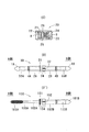
図1の(A)図に示されるのは、本発明の塗布具付両軸化粧料容器1を、化粧料が充填された容器本体3A、容器本体3Bと中継キャップ2を分離して示した図であり、中継キャップ2は、図2に示す(C)図の両ねじキャップ20に(D)図の一体棒軸30が嵌着された状態を指す。
The present invention will be described in detail with reference to the drawings.
FIG. 1A shows a biaxial
図1の(B)は、中継キャップ2の両開口の雌ねじ22,23に容器本体3A、3Bが螺合して、塗布具付両軸化粧料容器1が一体化した状態を示すものである。
FIG. 1B shows a state in which the container
実施例の塗布具付両軸化粧料容器1は、塗布具1A,1Bにチップが固着され、容器本体3A、3B内に粉状化粧料が充填されたチップオンパウダーの両軸式化粧料容器となっている。
The biaxial
中継キャップ2を構成する両ねじキャップ20は、図2の(C)に示されるように、円筒外筒21として形成され、貫通孔24を有し、開口孔A,開口孔Bのそれぞれ内径に雌ねじ22,雌ねじ23を備え、開口孔A側にスプライン25と一体棒軸30を固定する凹部26が一カ所設置される。この両ねじキャップ20は射出成形金型で製作され、射出成形によって形成される。
As shown in FIG. 2 (C), both
(D)図は一体棒軸30を示し、嵌着部34には前記両ねじキャップ20と一体化する嵌合凸部31と縦リブ32が設置される。又、棒軸2A、棒軸2B先端には腔部33A、腔部33Bが穿設され、ここに塗布具1A,塗布具1Bが固着される。棒軸2A、棒軸2BにはそれぞれOリング溝4A,4Bが設けられる。
(D) The figure shows the integrated
次に両ねじキャップ20と、一体棒軸30の組み付けについて説明する。
一体棒軸30は、両ねじキャップ20の開口孔A側より一体棒軸30のB側を挿入していき、塗布具1B、棒軸2Bが開口孔B側より突出した時点で縦リブ32とスプライン25が係合し、凹部26に嵌合凸部31が嵌着することで回動不能脱落不能に一体棒軸30が両ねじキャップ20内に嵌着し、中継キャップ2を形成する。そのため組み付けは、一体棒軸30を貫通させ嵌着させる一工程で終了する。
Next, the assembly of the two
The
本発明は、両端に塗布具を固定した一体棒軸30を貫通孔24を有する両ねじキャップ20の凹部26が設けられた開口孔A側より一体棒軸30のB側を挿入して中継キャップ2を構成することで、部材の減少と組み付け回数を減らし、コストの低減を目的とした発明である。
The present invention inserts the B side of the integrated
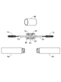
実施例における図3は、容器本体3A、3Bを示し、チップオンパウダーの容器本体3A、3Bの各部材を示した図であり、(E)は本体筒70で、口栓72には雄ねじ71が配され、口栓72より下部は外筒73として外観が形成され、前端開口孔76より貫通孔が後端開口孔77まで穿設され、内径にカップ40が回動不能に縦摺動するための摺動溝74が設けられている。
FIG. 3 in the embodiment shows the container
(F)は粉状化粧料aが腔部41に充填されたカップ40を示し、カップ40の外周には前記本体筒70内径の摺動溝74に係合する係合突起42が設けられている。そのため、カップ40は回動不能に後述する弾発スプリング50によって摺動する。
(F) shows the
(J)は弾発スプリング50を示し、前端部51はカップ40の底部43に当接し、後端部52は尾栓60の底面61に当接してカップ40を常時前端開口孔76側に付勢している。
(J) shows the
(K)は尾栓60を示し、本体筒70の後端開口孔77端部とフランジ63の上端面が当接するとともに、尾栓嵌合部75と凸部62との嵌合によって、本体筒70と一体化する。
(K) shows the
なお、容器本体3Aと容器本体3Bは、図3における各部材が同じに使用され、カップ40内に充填される化粧料が粉状化粧料aと粉状化粧料bとして異なって充填され、図1の(A)(B)における両軸のチップオンパウダー容器を構成する。
In addition, each of the members in FIG. 3 is used in the same manner in the
作用を説明する。
図1の(B)の状態から中継キャップ2と使用したい方の容器本体、例えば3Aの外筒73を持って回動すると、雌ねじ22に螺合していた口栓72の雄ねじ71は螺合が解けると同時に塗布具1Aはカップ40内の粉状化粧料aに当接しながら回動するため、塗布具1Aに適量の粉状化粧料aが塗布される。使用者はこの塗布具1Aに塗布された粉状化粧料aを肌に塗布することで化粧を施す。又、棒軸2Aを容器本体3A内に戻して、中継キャップ2と逆に回動することで、仕舞うことが出来る。粉状化粧料b側を使用したい場合は、中継キャップ2と容器本体3Bを回動して粉状化粧料aの使用時と同様に化粧を施すことが出来る。
The operation will be described.
When the container body to be used with the
図1の(B)の中継キャップ2部分を(L)として、図4に斜視図として開示してある。容器本体3A、3Bの口栓72の外径寸法Xは、中継キャップ2を構成する両ねじキャップ20の開口孔A、Bに挿入可能と同時にA側下向き段部28及びB側下向き段部29の内径寸法よりやや大きく設定され、それぞれの下向き段部28、29に当接することで螺合の完了としてもよく、又、容器本体3A、3Bの口栓72下の段部78と両ねじキャップ20の端面27に当接する状態で螺合完了としてもよい。
The
図2の(D’)に他の実施例としての一体棒軸130が開示され、A側にはマスカラブラシ101Aが、B側にはチップ101Bが固着され、A側の容器本体内には、図5に示すボトル4aと同様なマスカラ液が充填されるとともに、B側は前期実施例と同様な粉状化粧料が充填され、液状化粧料と粉状化粧料とを使用可能にする一体棒軸130が示され、この一体棒軸130も図2の(C)の両ねじキャップ20に固着可能となっている。
(D ') of FIG. 2 discloses an integrated
(C)に記載される両ねじキャップ20の開口孔A側より一体棒軸130のチップ101B側を挿入して、嵌合凸部131と縦リブ132によって凹部26に嵌合するとともに、スプライン25によって回動不能に組み付けられる。
The
本発明は、塗布具付両軸化粧料容器であり、貫通孔24を有する両ねじキャップ20を使用することで、両端に固着された塗布具を備えた一体棒軸30,130を1回の行程で両ねじキャップ20に組み付けることで、部材の減少と組付工数を減らし、コスト削減を目的とした発明である。
The present invention is a biaxial cosmetic container with an applicator, and by using a
1・・・・ 塗布具付両軸化粧料容器
A・・・・ 開口孔
B・・・・ 開口孔
a(b)・・ 粉状化粧料
1A・・・ 塗布具
1B・・・ 塗布具
2・・・・ 中継キャップ
2A・・・ 棒軸
2B・・・ 棒軸
3A・・・ 容器本体
3B・・・ 容器本体
4A・・・ Oリング溝
4B・・・ Oリング溝
20・・・ 両ねじキャップ
21・・・ 円筒外筒
22・・・ 雌ねじ
23・・・ 雌ねじ
24・・・ 貫通孔
25・・・ スプライン
26・・・ 凹部
30・・・ 一体棒軸
31・・・ 嵌合凸部
32・・・ 縦リブ
33A・・ 腔部
33B・・ 腔部
34・・・ 嵌着部
40・・・ カップ
41・・・ 腔部
43・・・ 底部
60・・・ 尾栓
62・・・ 凸部
63・・・ フランジ
70・・・ 本体筒
71・・・ 雄ねじ
72・・・ 口栓
73・・・ 外筒
74・・・ 摺動溝
76・・・ 前端開口孔
77・・・ 後端開口孔
80・・・ 継具
81・・・ 接続部分
82・・・ フランジ部
83・・・ 雌ねじ
DESCRIPTION OF
Claims (1)
前記中継キャップは、
貫通孔を有し、貫通孔内に凹部及びスプライン部を形成するとともに貫通孔両端内周にそれぞれ雌ねじを形成する両ねじキャップと、
凸部及び縦リブが形成された軸の両端に塗布具が固着された一体棒軸と、を備え、
前記一体棒軸は、前記貫通孔を挿通し、前記凸部が前記凹部に嵌合して前記縦リブが前記スプライン部に係合することで、前記両ねじキャップに回動不能脱落不能に固定されることを特徴とする塗布具付両軸化粧料容器。 Two container bodies filled with cosmetics, a relay cap screwed into the caps of the two container bodies, and a rod shaft extending from the opening holes at both ends of the relay cap. A biaxial cosmetic container with an applicator for applying makeup by applying the cosmetic in each container body to the applicator ,
The relay cap,
Both screw caps having through holes, forming recesses and spline parts in the through holes and forming female threads on both inner circumferences of the through holes,
An integral bar shaft with an applicator fixed to both ends of the shaft on which the convex portion and the vertical rib are formed, and
The integral rod shaft is fixed to the both screw caps so that it cannot be turned off by being inserted through the through hole, the convex portion is fitted into the concave portion, and the vertical rib is engaged with the spline portion. A biaxial cosmetic container with an applicator.
Priority Applications (1)
| Application Number | Priority Date | Filing Date | Title |
|---|---|---|---|
| JP2004369575A JP4473720B2 (en) | 2004-12-21 | 2004-12-21 | Biaxial cosmetic container with applicator |
Applications Claiming Priority (1)
| Application Number | Priority Date | Filing Date | Title |
|---|---|---|---|
| JP2004369575A JP4473720B2 (en) | 2004-12-21 | 2004-12-21 | Biaxial cosmetic container with applicator |
Publications (3)
| Publication Number | Publication Date |
|---|---|
| JP2006174936A JP2006174936A (en) | 2006-07-06 |
| JP2006174936A5 JP2006174936A5 (en) | 2006-08-24 |
| JP4473720B2 true JP4473720B2 (en) | 2010-06-02 |
Family
ID=36729579
Family Applications (1)
| Application Number | Title | Priority Date | Filing Date |
|---|---|---|---|
| JP2004369575A Active JP4473720B2 (en) | 2004-12-21 | 2004-12-21 | Biaxial cosmetic container with applicator |
Country Status (1)
| Country | Link |
|---|---|
| JP (1) | JP4473720B2 (en) |
Families Citing this family (9)
| Publication number | Priority date | Publication date | Assignee | Title |
|---|---|---|---|---|
| US9237992B2 (en) | 2009-10-27 | 2016-01-19 | The Procter & Gamble Company | Two-step mascara product |
| US10034829B2 (en) | 2010-10-27 | 2018-07-31 | Noxell Corporation | Semi-permanent mascara compositions |
| US9216145B2 (en) | 2009-10-27 | 2015-12-22 | The Procter & Gamble Company | Semi-permanent cosmetic concealer |
| US9004791B2 (en) | 2010-04-30 | 2015-04-14 | The Procter & Gamble Company | Package for multiple personal care compositions |
| US9173824B2 (en) | 2011-05-17 | 2015-11-03 | The Procter & Gamble Company | Mascara and applicator |
| WO2013173452A2 (en) | 2012-05-15 | 2013-11-21 | The Procter & Gamble Company | Method for quantitatively determining eyelash clumping |
| KR200473412Y1 (en) | 2012-10-12 | 2014-07-04 | 임종백 | A Dual Cosmetic Container |
| KR101636268B1 (en) * | 2014-09-29 | 2016-07-07 | (주)연우 | The container containing different kinds of contents |
| JP6823362B2 (en) * | 2015-06-01 | 2021-02-03 | 紀伊産業株式会社 | Cosmetic container with painter |
-
2004
- 2004-12-21 JP JP2004369575A patent/JP4473720B2/en active Active
Also Published As
| Publication number | Publication date |
|---|---|
| JP2006174936A (en) | 2006-07-06 |
Similar Documents
| Publication | Publication Date | Title |
|---|---|---|
| US7972073B2 (en) | Cosmetic product distributor applicator | |
| US6572296B2 (en) | Containers simulating collapsible tubes, packages including such containers, and methods of making them | |
| CN103653685B (en) | Cosmetic material application container | |
| US8434955B2 (en) | Cosmetic unit | |
| JP4473720B2 (en) | Biaxial cosmetic container with applicator | |
| JP5303177B2 (en) | Cosmetic unit comprising two connecting part units | |
| JP2003289942A (en) | Cosmetic unit | |
| US9486054B2 (en) | Applying material extruding container | |
| JP3134864U (en) | Dual type refill container | |
| JPH0129563B2 (en) | ||
| JP2005230194A (en) | Moving substance feeder | |
| JP4739847B2 (en) | Filler extrusion container | |
| JP4740183B2 (en) | Coating material extrusion container | |
| JP5385884B2 (en) | Cosmetic container | |
| JP2019519293A (en) | Hinged applicators for cosmetic products and associated packaging and application assemblies | |
| KR102198117B1 (en) | Application container | |
| JP4495640B2 (en) | Contents extrusion container | |
| KR200255113Y1 (en) | Makeup pencil case | |
| JP2551942Y2 (en) | Liquid container application container | |
| JP4111741B2 (en) | Stick-shaped cosmetic container | |
| JP7329234B2 (en) | Application material extrusion container | |
| KR200260229Y1 (en) | Eye liner | |
| JP4662297B2 (en) | Stick-shaped cosmetics feeding container | |
| JP5006612B2 (en) | Cosmetic material applicator container | |
| JP3616044B2 (en) | Stick-shaped cosmetic material feeding container |
Legal Events
| Date | Code | Title | Description |
|---|---|---|---|
| A521 | Request for written amendment filed |
Free format text: JAPANESE INTERMEDIATE CODE: A523 Effective date: 20060707 |
|
| A621 | Written request for application examination |
Free format text: JAPANESE INTERMEDIATE CODE: A621 Effective date: 20060707 |
|
| A977 | Report on retrieval |
Free format text: JAPANESE INTERMEDIATE CODE: A971007 Effective date: 20090929 |
|
| A131 | Notification of reasons for refusal |
Free format text: JAPANESE INTERMEDIATE CODE: A131 Effective date: 20091208 |
|
| RD03 | Notification of appointment of power of attorney |
Free format text: JAPANESE INTERMEDIATE CODE: A7423 Effective date: 20091218 |
|
| A521 | Request for written amendment filed |
Free format text: JAPANESE INTERMEDIATE CODE: A523 Effective date: 20100122 |
|
| TRDD | Decision of grant or rejection written | ||
| A01 | Written decision to grant a patent or to grant a registration (utility model) |
Free format text: JAPANESE INTERMEDIATE CODE: A01 Effective date: 20100216 |
|
| A01 | Written decision to grant a patent or to grant a registration (utility model) |
Free format text: JAPANESE INTERMEDIATE CODE: A01 |
|
| A61 | First payment of annual fees (during grant procedure) |
Free format text: JAPANESE INTERMEDIATE CODE: A61 Effective date: 20100305 |
|
| FPAY | Renewal fee payment (event date is renewal date of database) |
Free format text: PAYMENT UNTIL: 20130312 Year of fee payment: 3 |
|
| R150 | Certificate of patent or registration of utility model |
Ref document number: 4473720 Country of ref document: JP Free format text: JAPANESE INTERMEDIATE CODE: R150 Free format text: JAPANESE INTERMEDIATE CODE: R150 |
|
| FPAY | Renewal fee payment (event date is renewal date of database) |
Free format text: PAYMENT UNTIL: 20140312 Year of fee payment: 4 |
|
| R250 | Receipt of annual fees |
Free format text: JAPANESE INTERMEDIATE CODE: R250 |
|
| R250 | Receipt of annual fees |
Free format text: JAPANESE INTERMEDIATE CODE: R250 |
|
| R250 | Receipt of annual fees |
Free format text: JAPANESE INTERMEDIATE CODE: R250 |
|
| R250 | Receipt of annual fees |
Free format text: JAPANESE INTERMEDIATE CODE: R250 |
|
| R250 | Receipt of annual fees |
Free format text: JAPANESE INTERMEDIATE CODE: R250 |
|
| R250 | Receipt of annual fees |
Free format text: JAPANESE INTERMEDIATE CODE: R250 |
|
| R250 | Receipt of annual fees |
Free format text: JAPANESE INTERMEDIATE CODE: R250 |
|
| R250 | Receipt of annual fees |
Free format text: JAPANESE INTERMEDIATE CODE: R250 |
|
| R250 | Receipt of annual fees |
Free format text: JAPANESE INTERMEDIATE CODE: R250 |
|
| R250 | Receipt of annual fees |
Free format text: JAPANESE INTERMEDIATE CODE: R250 |
|
| R250 | Receipt of annual fees |
Free format text: JAPANESE INTERMEDIATE CODE: R250 |