JP4473389B2 - Magnetic resonance imaging system - Google Patents
Magnetic resonance imaging system Download PDFInfo
- Publication number
- JP4473389B2 JP4473389B2 JP36129899A JP36129899A JP4473389B2 JP 4473389 B2 JP4473389 B2 JP 4473389B2 JP 36129899 A JP36129899 A JP 36129899A JP 36129899 A JP36129899 A JP 36129899A JP 4473389 B2 JP4473389 B2 JP 4473389B2
- Authority
- JP
- Japan
- Prior art keywords
- pulse
- flip
- magnetic resonance
- frequency
- resonance imaging
- Prior art date
- Legal status (The legal status is an assumption and is not a legal conclusion. Google has not performed a legal analysis and makes no representation as to the accuracy of the status listed.)
- Expired - Lifetime
Links
- 238000002595 magnetic resonance imaging Methods 0.000 title claims description 13
- 230000036278 prepulse Effects 0.000 claims description 50
- 230000001629 suppression Effects 0.000 claims description 13
- 238000003384 imaging method Methods 0.000 claims description 10
- 230000003247 decreasing effect Effects 0.000 claims description 4
- 238000000034 method Methods 0.000 description 24
- 238000001208 nuclear magnetic resonance pulse sequence Methods 0.000 description 10
- 238000010586 diagram Methods 0.000 description 7
- 239000000523 sample Substances 0.000 description 5
- 230000007423 decrease Effects 0.000 description 4
- 238000013480 data collection Methods 0.000 description 3
- 230000003068 static effect Effects 0.000 description 3
- 238000002583 angiography Methods 0.000 description 2
- 230000005540 biological transmission Effects 0.000 description 2
- 230000017531 blood circulation Effects 0.000 description 2
- 230000000694 effects Effects 0.000 description 2
- 230000005284 excitation Effects 0.000 description 2
- XLYOFNOQVPJJNP-UHFFFAOYSA-N water Substances O XLYOFNOQVPJJNP-UHFFFAOYSA-N 0.000 description 2
- 206010006322 Breath holding Diseases 0.000 description 1
- 239000008280 blood Substances 0.000 description 1
- 210000004369 blood Anatomy 0.000 description 1
- 210000004556 brain Anatomy 0.000 description 1
- 230000007274 generation of a signal involved in cell-cell signaling Effects 0.000 description 1
- 230000005415 magnetization Effects 0.000 description 1
- 238000012986 modification Methods 0.000 description 1
- 230000004048 modification Effects 0.000 description 1
- 210000000056 organ Anatomy 0.000 description 1
- 238000000079 presaturation Methods 0.000 description 1
- 230000002035 prolonged effect Effects 0.000 description 1
- 239000000126 substance Substances 0.000 description 1
Images


Classifications
-
- G—PHYSICS
- G01—MEASURING; TESTING
- G01R—MEASURING ELECTRIC VARIABLES; MEASURING MAGNETIC VARIABLES
- G01R33/00—Arrangements or instruments for measuring magnetic variables
- G01R33/20—Arrangements or instruments for measuring magnetic variables involving magnetic resonance
- G01R33/44—Arrangements or instruments for measuring magnetic variables involving magnetic resonance using nuclear magnetic resonance [NMR]
- G01R33/48—NMR imaging systems
- G01R33/4818—MR characterised by data acquisition along a specific k-space trajectory or by the temporal order of k-space coverage, e.g. centric or segmented coverage of k-space
- G01R33/482—MR characterised by data acquisition along a specific k-space trajectory or by the temporal order of k-space coverage, e.g. centric or segmented coverage of k-space using a Cartesian trajectory
Landscapes
- Physics & Mathematics (AREA)
- High Energy & Nuclear Physics (AREA)
- Condensed Matter Physics & Semiconductors (AREA)
- General Physics & Mathematics (AREA)
- Magnetic Resonance Imaging Apparatus (AREA)
Description
【0001】
【発明の属する技術分野】
本発明は、磁気共鳴診断装置に係り、特にフリップパルス(高周波励起パルス)を印加する前に印加する脂肪抑制パルス等のプリパルスの印加方法の改良に関する。
【0002】
【従来の技術】
プリパルスとして代表的な脂肪抑制パルスは、脂肪と水との間の化学シフトに従って狭帯域化したフリップパルスで、脂肪だけを選択的に励起し、その後に勾配磁場をかけて十分にディフェーズし、それにより脂肪からの磁気共鳴信号(MR信号)を低減するというものである。最近では、脂肪抑制パルスは、特に、MRアンギオグラフィー(MRA)では、その画質を向上させるものとして不可欠とされている。
【0003】
周知の通り、MRAの原理は、撮影領域内の脳実質や臓器等の静止物体はその縦磁化があまり回復していないうちに次々と励起されるので信号レベルは徐々に低くなっていくが、血液(水)は常にフレッシュな状態で撮影領域に流入してくるので、静止物体ほどは信号低下は見られない。このため血流が静止物体に比べて相対的に強調されたような画像(血流画像)が得られることになる。このようなMRAで、画質向上のために、フリップパルスの印加直前に脂肪抑制パルスをプリパルスとして印加して、脂肪抑制を図っている。
【0004】
上述したように脂肪抑制パルスを狭帯域化するために、脂肪抑制パルスのパルス幅を例えば±π長から±4・π長に延長することが必要とされる。このため画像生成に必要な全データを収集するのに必要とされる撮影時間が長時間化してしまい、1回の息止め時間内に撮影を完了できない、患者負担が増大する、体動アーチファクトの発生機会が増えるといった臨床上様々な不都合が生じる。
【0005】
【発明が解決しようとする課題】
本発明の目的は、脂肪抑制パルス等のプリパルスを使う磁気共鳴診断装置において、必要な画像コントラストを確保しながら、撮影時間をできるだけ短縮することにある。
【0006】
【課題を解決するための手段】
本発明は、フリップパルスを繰り返し印加し、前記フリップパルス各々の印加後に2DFT又は3DFTの映像法に従ってエンコードをかけた1又は複数のMR信号を受信し、この受信したMR信号に基づいて画像を生成する磁気共鳴映像装置において、前記フリップパルスに対する脂肪抑制効果を有するプリパルスの印加頻度をK空間上でゼロエンコードを中心とした低周波領域内において外側に向かって段階的に低下させることを特徴とする。
【0007】
(2)本発明は、フリップパルスを繰り返し印加し、フリップパルス各々の印加後に2DFT又は3DFTの映像法に従ってエンコードをかけた1又は複数のMR信号を受信し、この受信したMR信号に基づいて画像を生成する磁気共鳴映像装置において、前記フリップパルスに対するプリパルスの印加頻度が経時的に変動するように前記プリパルスを発生することを特徴とする。
【0008】
(3)本発明は、(1)の磁気共鳴映像装置において、前記K空間上の最外部分では前記フリップパルスに対してプリパルスが印加されないことを特徴とする。
【0009】
(4)本発明は、(2)の磁気共鳴映像装置において、特定の期間では前記フリップパルスに対してプリパルスが印加されないことを特徴とする。
【0010】
(5)本発明は、(1)又は(2)の磁気共鳴映像装置において、前記プリパルスは脂肪抑制パルスであることを特徴とする。
【0011】
【発明の実施の形態】
以下、本発明による磁気共鳴映像装置を実施形態により図面を参照して詳細に説明する。
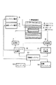
図1は本発明の一実施形態に係る磁気共鳴映像装置の構成を示す図である。例えば円筒形の静磁場磁石1の内側には、計算機システム12の制御のもとでシムコイル電源6から電力供給を受けて静磁場均一性を高めるための磁場を発生するシムコイル3、直交3軸に関して個々に勾配磁場パルスを発生する勾配コイル2、被検体に高周波磁場パルス(RFパルス)を印加すると共に被検体からのMR信号を受信するプローブ(RFコイル)4が設けられている。なお、プローブ4は、送受信兼用でなくとも、送信用と受信用とを別々に設けてもよい。
【0012】
シーケンス制御部10は、勾配コイル2を介して被検体に勾配磁場パルスを印加する勾配コイル電源5、プローブ4を介して高周波磁場パルスを被検体に印加する送信器7、プローブ4を介して被検体からのMR信号を受信する受信器9、さらに受信器9を介して受信されたMR信号を収集するデータ収集部11を所定のパルスシーケンスに従って制御する。計算機システム12は、装置全体のホストコンピュータとしての機能の他に、データ収集部11で収集されたMR信号に基づいて2DFT(2次元フーリエ変換)法又は3DFT(3次元フーリエ変換)法によりMR画像を生成する演算機能を有している。表示ディスプレイ14は、計算機システム12で生成されたMR画像及び各種情報を表示するために設けられている。
【0013】
上述のシーケンス制御部10の制御により実行されるパルスシーケンスとしては、スピンエコー(SE)法、フィールドエコー(FE)法、エコープラナー(EPI)法等の中の特定のパルスシーケンスに設定され、又はそれらの中から操作者によりコンソール13を介して任意に選択的である。また、このパルスシーケンスには、脂肪抑制パルス等のプリパルスを挿入可能であり、このプリパルスの印加方法についてシーケンス制御部10で制御可能になっている。このプリパルスの印加方法は本発明で特徴的であり、以下に詳述する。なお、プリパルスとしては、脂肪抑制パルス以外の例としては、プレサチュレーションパルス、タギング、MTC等がある。
【0014】
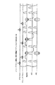
図2には、MR信号発生技法としてスピンワープ法を、また画像化技法として3DFT法を採用した場合において、フリップパルス(高周波励起パルス)を1回印加する毎に1回という頻度でプリパルスを印加するときのパルスシーケンスを示している。周知の通り、3DFT法では、勾配コイル2で発生される勾配軸の異なる3つの勾配磁場パルスのうち、ある軸の勾配磁場(RO)はMR信号に周波数エンコードをかけるために用いられ、他の軸の勾配磁場(SLICE)はスライス選択及びMR信号にスライスエンコードをかけるために用いられ、残りの軸の勾配磁場(PE)はMR信号に位相エンコードをかけるために用いられる。なお、2次元フーリエ変換法(2DFT法)では、3DFT法との違いとして、勾配磁場(SLICE)はスライスエンコードには使われないで、スライス選択のみに用いられる。
【0015】
この3DFT法において、フリップパルスは、スライスエンコードと位相エンコードのパターンを少しずつ変えながら、繰り返し時間TRの周期で繰り返し印加されるが、図2のケースでは、フリップパルス各々に対してプリパルスを1回ずつ印加するようになっている。
【0016】
図3には、フリップパルスを2回印加する毎に1回という頻度でプリパルスを印加するときのパルスシーケンスを示している。つまり、このケースでは、隣り合うペアのフリップパルスの一方にはそれに対応してプリパルスを印加するが、他方のフリップパルスに対してはプリパルスを印加しない。
【0017】
図4には、フリップパルスを3回印加する毎に1回という頻度でプリパルスを印加するときのパルスシーケンスを示している。つまり、このケースでは、連続する3つのフリップパルスの1つにはそれに対応してプリパルスを印加するが、他の残りの2つのフリップパルスに対してはプリパルスを印加しない。
【0018】
図5には、3DFT法におけるK空間におけるプリパルスの印加頻度の変化を示している。画像コントラストに最も影響するK空間のゼロエンコードを中心とした所定の領域(中心領域)のMR信号を収集する期間には、図2に示したフリップパルス1回に対して1回という頻度でプリパルスを印加する。当該中心領域の外側の領域(中間領域)のMR信号を収集する期間には、図3に示したフリップパルス2回に対して1回という頻度でプリパルスを印加する。当該中間領域の外側の領域(外領域)のMR信号を収集する期間には、図4に示したフリップパルス3回に対して1回という頻度でプリパルスを印加する。そして、当該外領域よりさらに外側の画像コントラストに最も影響の少ない最外領域のMR信号を収集する期間には、フリップパルスに対してプリパルスを印加しない。なお、造影アンギオ撮影では、撮影開始直後のコントラストを重視するため、空打ち後、プリパルス及びフリップパルスの印加を開始する。
【0019】
このようにK空間上でゼロエンコードから外側に向かってフリップパルスに対するプリパルスの印加頻度を少しずつ低下させていき、最外領域ではプリパルスを印加しないことにより、K空間の全領域を均等に、1回のフリップパルスに対してプリパルスを1回ずつ印加するよりも、撮影時間を大幅に短縮することができる。また、プリパルスの頻度を画像コントラストに対して影響の大きい中心領域から外側に向かって低下させていくので、画像コントラストの著しい低下を抑制することができる。
【0020】
また、図6に示すように、2DFT法にも適用することができる。つまり、画像コントラストに最も影響するK空間の中心領域のMR信号を収集する期間には、フリップパルス1回に対して1回という頻度でプリパルスを印加し、中間領域のMR信号を収集する期間にはフリップパルス2回に対して1回という頻度でプリパルスを印加し、外領域のMR信号を収集する期間にはフリップパルス3回に対して1回という頻度でプリパルスを印加し、そして、最外領域のMR信号を収集する期間にはフリップパルスに対してプリパルスを印加しない。このように2DFT法でも、K空間上でゼロエンコードから外側に向かってフリップパルスに対するプリパルスの印加頻度を少しずつ低下させていき、最外領域ではプリパルスを印加しないことにより3DFT法の場合と同様の効果を奏することができる。
【0021】
本発明は上述した実施形態に限定されず、種々変形して実施可能である。例えば、上述の説明では、K空間上の中心領域から外側に向かって、プリパルスのフリップパルスに対する頻度を1回に1回、2回に1回、3回に1回と減らしていたが、これに限定されず、1回に1回、3回に1回、5回に1回のように段階的に減らしてもよいし、その他様々なパターンで頻度を変化させてもよい。また、K空間上での領域と頻度との対応関係を任意に設定することにより、画像コントラストを任意に調整することも可能である。
【0022】
【発明の効果】
本発明によると、脂肪抑制パルス等のプリパルスを使った磁気共鳴診断装置において、必要な画像コントラストを最低限確保しながら、撮影時間の短縮を図ることができる。
【図面の簡単な説明】
【図1】本発明の一実施形態による磁気共鳴映像装置の構成を示す図。
【図2】本実施形態において、1回のフリップパルスに対して1回の頻度でプリパルスを印加する場合のパルスシーケンスの一例を示す図。
【図3】本実施形態において、2回のフリップパルスに対して1回の頻度でプリパルスを印加する場合のパルスシーケンスの一例を示す図。
【図4】本実施形態において、3回のフリップパルスに対して1回の頻度でプリパルスを印加する場合のパルスシーケンスの一例を示す図。
【図5】本実施形態において、3DFT法のK空間におけるプリパルスの印加頻度の変化を示す図。
【図6】本実施形態において、2DFT法のK空間におけるプリパルスの印加頻度の変化を示す図。
【符号の説明】
1…静磁場磁石、
2…勾配コイル、
3…シムコイル、
4…プローブ、
5…勾配コイル電源、
6…シムコイル電源、
7…送信器、
9…受信器、
10…シーケンス制御部、
11…データ収集部、
12…計算機システム、
13…コンソール、
14…画像ディスプレイ。[0001]
BACKGROUND OF THE INVENTION
The present invention relates to a magnetic resonance diagnostic apparatus, and more particularly to an improvement in a method for applying a pre-pulse such as a fat suppression pulse applied before applying a flip pulse (high-frequency excitation pulse).
[0002]
[Prior art]
A typical fat suppression pulse as a pre-pulse is a flip pulse narrowed according to the chemical shift between fat and water, which selectively excites only fat and then fully dephases it by applying a gradient magnetic field, Thereby, the magnetic resonance signal (MR signal) from fat is reduced. Recently, fat suppression pulses are indispensable for improving the image quality, particularly in MR angiography (MRA).
[0003]
As is well known, the principle of MRA is that a stationary object such as a brain parenchyma or an organ in an imaging region is excited one after another while its longitudinal magnetization has not recovered much, so the signal level gradually decreases. Since blood (water) always flows into the imaging region in a fresh state, the signal is not lowered as much as a stationary object. For this reason, an image (blood flow image) in which blood flow is relatively emphasized as compared with a stationary object is obtained. In such MRA, fat suppression is applied by applying a fat suppression pulse as a pre-pulse immediately before the application of the flip pulse in order to improve image quality.
[0004]
As described above, in order to narrow the fat suppression pulse, it is necessary to extend the pulse width of the fat suppression pulse from ± π length to ± 4 · π length, for example. For this reason, the imaging time required to collect all the data necessary for image generation is prolonged, and imaging cannot be completed within one breath holding time, which increases the burden on the patient, and causes body motion artifacts. Various clinical inconveniences such as increased chances of occurrence occur.
[0005]
[Problems to be solved by the invention]
An object of the present invention is to shorten the imaging time as much as possible while ensuring a necessary image contrast in a magnetic resonance diagnostic apparatus using a pre-pulse such as a fat saturation pulse.
[0006]
[Means for Solving the Problems]
The present invention repeatedly applies flip pulses, receives one or a plurality of MR signals encoded according to the 2DFT or 3DFT video method after applying each of the flip pulses, and generates an image based on the received MR signals In the magnetic resonance imaging apparatus, the application frequency of the pre-pulse having a fat suppression effect on the flip pulse is gradually decreased outward in a low frequency region centered on zero encoding on the K space. .
[0007]
(2) The present invention repeatedly applies flip pulses, receives one or more MR signals encoded according to the 2DFT or 3DFT video method after each flip pulse is applied, and generates an image based on the received MR signals. In the magnetic resonance imaging apparatus for generating the pre-pulse, the pre-pulse is generated so that the frequency of application of the pre-pulse to the flip pulse varies with time.
[0008]
(3) In the magnetic resonance imaging apparatus of (1), the present invention is characterized in that a pre-pulse is not applied to the flip pulse at the outermost part in the K space.
[0009]
(4) In the magnetic resonance imaging apparatus of (2), the present invention is characterized in that a pre-pulse is not applied to the flip pulse in a specific period.
[0010]
(5) According to the present invention, in the magnetic resonance imaging apparatus of (1) or (2), the pre-pulse is a fat suppression pulse.
[0011]
DETAILED DESCRIPTION OF THE INVENTION
Hereinafter, a magnetic resonance imaging apparatus according to the present invention will be described in detail with reference to the drawings.
FIG. 1 is a diagram showing a configuration of a magnetic resonance imaging apparatus according to an embodiment of the present invention. For example, inside the cylindrical static
[0012]
The
[0013]
The pulse sequence executed by the control of the above-described
[0014]
In FIG. 2, when the spin warp method is employed as the MR signal generation technique and the 3DFT method is employed as the imaging technique, a pre-pulse is applied at a frequency of once every time a flip pulse (high frequency excitation pulse) is applied. The pulse sequence is shown. As is well known, in the 3DFT method, out of three gradient magnetic field pulses with different gradient axes generated by the
[0015]
In this 3DFT method, the flip pulse is repeatedly applied at a cycle of the repetition time TR while changing the slice encoding and phase encoding patterns little by little. In the case of FIG. 2, a pre-pulse is applied once for each flip pulse. They are applied one by one.
[0016]
FIG. 3 shows a pulse sequence when a pre-pulse is applied at a frequency of once every time a flip pulse is applied twice. That is, in this case, a pre-pulse is applied to one of adjacent pairs of flip pulses, but no pre-pulse is applied to the other flip pulse.
[0017]
FIG. 4 shows a pulse sequence when a pre-pulse is applied at a frequency of once every time a flip pulse is applied three times. That is, in this case, a pre-pulse is applied to one of the three consecutive flip pulses, but no pre-pulse is applied to the remaining two flip pulses.
[0018]
FIG. 5 shows a change in prepulse application frequency in the K space in the 3DFT method. In a period in which MR signals in a predetermined region (center region) centering on zero encoding in the K space that most affects the image contrast are collected, a pre-pulse is performed at a frequency of once for each flip pulse shown in FIG. Is applied. In a period in which MR signals in the region outside the central region (intermediate region) are collected, a pre-pulse is applied at a frequency of once for every two flip pulses shown in FIG. In the period in which MR signals in the region outside the intermediate region (outer region) are collected, a pre-pulse is applied at a frequency of once for three flip pulses shown in FIG. Then, no pre-pulse is applied to the flip pulse during a period in which MR signals in the outermost region having the least influence on the image contrast outside the outer region are collected. In contrast angiography, since the contrast immediately after the start of imaging is emphasized, application of prepulses and flip pulses is started after idle shooting.
[0019]
As described above, the frequency of applying the pre-pulse to the flip pulse gradually decreases from the zero encoding toward the outside in the K space, and the pre-pulse is not applied in the outermost region, so that the entire region of the K space is uniformly 1 The imaging time can be significantly shortened compared to the case where a pre-pulse is applied once for each flip pulse. Further, since the frequency of the pre-pulse is decreased from the central region having a large influence on the image contrast toward the outside, it is possible to suppress a significant decrease in the image contrast.
[0020]
Further, as shown in FIG. 6, the present invention can also be applied to the 2DFT method. That is, during the period in which the MR signal in the central region of the K space that most affects the image contrast is collected, the pre-pulse is applied at a frequency of once per flip pulse, and the MR signal in the intermediate region is collected. Applies a pre-pulse at a frequency of once per two flip pulses, applies a pre-pulse at a frequency of once per three flip pulses during the period of collecting MR signals in the outer region, and the outermost No pre-pulse is applied to the flip pulse during the period in which the MR signal of the region is collected. As described above, even in the 2DFT method, the frequency of applying the prepulse to the flip pulse gradually decreases from the zero encoding to the outside in the K space, and the prepulse is not applied in the outermost region, so that the same as in the case of the 3DFT method. There is an effect.
[0021]
The present invention is not limited to the embodiment described above, and can be implemented with various modifications. For example, in the above description, the frequency of the pre-pulse with respect to the flip pulse is reduced from once to once, once every two times, and once every three times. However, the frequency may be decreased step by step, such as once at once, once every three times, once every five times, or may be changed in various other patterns. It is also possible to arbitrarily adjust the image contrast by arbitrarily setting the correspondence between the area in the K space and the frequency.
[0022]
【The invention's effect】
According to the present invention, in a magnetic resonance diagnostic apparatus using a pre-pulse such as a fat suppression pulse, the imaging time can be shortened while ensuring the necessary image contrast at a minimum.
[Brief description of the drawings]
FIG. 1 is a diagram showing a configuration of a magnetic resonance imaging apparatus according to an embodiment of the present invention.
FIG. 2 is a diagram showing an example of a pulse sequence in the case where a pre-pulse is applied at a frequency of one flip pulse in the present embodiment.
FIG. 3 is a diagram showing an example of a pulse sequence when a pre-pulse is applied at a frequency of once for two flip pulses in the present embodiment.
FIG. 4 is a diagram showing an example of a pulse sequence when a pre-pulse is applied at a frequency of once for three flip pulses in the present embodiment.
FIG. 5 is a diagram showing a change in prepulse application frequency in the 3DFT method K space in the present embodiment;
FIG. 6 is a diagram showing a change in prepulse application frequency in a 2DFT method K-space in the present embodiment;
[Explanation of symbols]
1 ... Static magnetic field magnet,
2 ... Gradient coil,
3 ... shim coil,
4 ... Probe,
5 ... Gradient coil power supply,
6 ... Shim coil power supply,
7 ... Transmitter,
9 ... Receiver,
10: Sequence control unit,
11 ... Data collection unit,
12 ... computer system,
13 ... Console,
14: Image display.
Claims (3)
前記フリップパルスに対する脂肪抑制効果を有するプリパルスの印加頻度をK空間上でゼロエンコードを中心とした低周波領域内において外側に向かって段階的に低下させることを特徴とする磁気共鳴映像装置。Magnetic resonance imaging that repeatedly applies flip pulses, receives one or a plurality of MR signals encoded according to 2DFT or 3DFT imaging methods after each flip pulse, and generates an image based on the received MR signals In the device
A magnetic resonance imaging apparatus characterized in that the application frequency of a pre-pulse having a fat suppression effect for the flip pulse is decreased stepwise outward in a low-frequency region centered on zero encoding in the K space .
Priority Applications (2)
| Application Number | Priority Date | Filing Date | Title |
|---|---|---|---|
| JP36129899A JP4473389B2 (en) | 1999-12-20 | 1999-12-20 | Magnetic resonance imaging system |
| US09/739,334 US6483307B2 (en) | 1999-12-20 | 2000-12-19 | MRI using variable ratio of pre-pulses to flip pulses |
Applications Claiming Priority (1)
| Application Number | Priority Date | Filing Date | Title |
|---|---|---|---|
| JP36129899A JP4473389B2 (en) | 1999-12-20 | 1999-12-20 | Magnetic resonance imaging system |
Related Child Applications (1)
| Application Number | Title | Priority Date | Filing Date |
|---|---|---|---|
| JP2009286317A Division JP2010057990A (en) | 2009-12-17 | 2009-12-17 | Magnetic resonance diagnosing device |
Publications (3)
| Publication Number | Publication Date |
|---|---|
| JP2001170023A JP2001170023A (en) | 2001-06-26 |
| JP2001170023A5 JP2001170023A5 (en) | 2007-02-08 |
| JP4473389B2 true JP4473389B2 (en) | 2010-06-02 |
Family
ID=18473010
Family Applications (1)
| Application Number | Title | Priority Date | Filing Date |
|---|---|---|---|
| JP36129899A Expired - Lifetime JP4473389B2 (en) | 1999-12-20 | 1999-12-20 | Magnetic resonance imaging system |
Country Status (2)
| Country | Link |
|---|---|
| US (1) | US6483307B2 (en) |
| JP (1) | JP4473389B2 (en) |
Families Citing this family (21)
| Publication number | Priority date | Publication date | Assignee | Title |
|---|---|---|---|---|
| US6933720B2 (en) | 2001-12-11 | 2005-08-23 | Toshiba America Mri, Inc. | Sequence preconditioning for ultra-fast magnetic resonance imaging |
| US7019524B2 (en) * | 2002-05-17 | 2006-03-28 | Ge Medical Systems Global Technology Company, Llc | Method, system and computer product for k-space correction of gradient non-linearities |
| JP3995542B2 (en) * | 2002-06-28 | 2007-10-24 | 東芝医用システムエンジニアリング株式会社 | Magnetic resonance imaging apparatus and magnetic resonance imaging data collection method |
| US7974679B2 (en) * | 2003-06-27 | 2011-07-05 | General Electric Company | Method and apparatus to reduce image intensity variation during MR data acquisition |
| JP3971726B2 (en) * | 2003-09-16 | 2007-09-05 | ジーイー・メディカル・システムズ・グローバル・テクノロジー・カンパニー・エルエルシー | Magnetic resonance imaging device |
| US7714575B2 (en) * | 2003-10-15 | 2010-05-11 | General Electric Company | Method and apparatus for enhanced magnetic preparation in MR imaging |
| US7941204B1 (en) * | 2004-11-16 | 2011-05-10 | Yi Wang | Magnetic resonance imaging concepts |
| US7323871B2 (en) * | 2005-07-07 | 2008-01-29 | General Electric Company | Method and system of MR imaging with simultaneous fat suppression and T1 inversion recovery contrast |
| US7330028B2 (en) * | 2005-09-26 | 2008-02-12 | General Electric Company | Apparatus and method of simultaneous fat suppression, magnetization transfer contrast, and spatial saturation for 3D time-of-flight imaging |
| JP2008220861A (en) * | 2007-03-15 | 2008-09-25 | Ge Medical Systems Global Technology Co Llc | Magnetic resonance imaging system and magnetic resonance imaging method |
| JP5037236B2 (en) * | 2007-06-20 | 2012-09-26 | ジーイー・メディカル・システムズ・グローバル・テクノロジー・カンパニー・エルエルシー | Magnetic resonance imaging apparatus and magnetic resonance image generation method |
| JP5132681B2 (en) * | 2007-07-02 | 2013-01-30 | 株式会社日立メディコ | Magnetic resonance imaging apparatus and magnetic resonance imaging method |
| US7990140B2 (en) * | 2007-10-04 | 2011-08-02 | Kabushiki Kaisha Toshiba | MRI apparatus |
| JP5361236B2 (en) * | 2008-03-31 | 2013-12-04 | 株式会社東芝 | Magnetic resonance imaging apparatus and imaging condition setting method |
| JP5280089B2 (en) * | 2008-04-23 | 2013-09-04 | ジーイー・メディカル・システムズ・グローバル・テクノロジー・カンパニー・エルエルシー | MRI equipment |
| JP2010051369A (en) * | 2008-08-26 | 2010-03-11 | Toshiba Corp | Magnetic resonance imaging apparatus |
| DE102011083890B4 (en) | 2011-09-30 | 2013-06-13 | Siemens Aktiengesellschaft | MR imaging with variable number of preparation pulses |
| JP5997984B2 (en) * | 2012-09-04 | 2016-09-28 | 株式会社日立製作所 | Magnetic resonance imaging apparatus and multi-echo measurement method |
| JP6496547B2 (en) | 2014-12-25 | 2019-04-03 | ジーイー・メディカル・システムズ・グローバル・テクノロジー・カンパニー・エルエルシー | Magnetic resonance equipment |
| KR102028126B1 (en) | 2017-09-27 | 2019-10-02 | 삼성전자주식회사 | Magnetic resonance image apparatus and method of generating magnetic resonance image |
| CN110495883A (en) * | 2018-05-17 | 2019-11-26 | 西门子(深圳)磁共振有限公司 | Magnetic Resonance Angiography method, apparatus, system and computer readable storage medium |
Family Cites Families (17)
| Publication number | Priority date | Publication date | Assignee | Title |
|---|---|---|---|---|
| JPH02255126A (en) * | 1989-03-29 | 1990-10-15 | Toshiba Corp | Magnetic resonance imaging method |
| NL8900990A (en) * | 1989-04-20 | 1990-11-16 | Philips Nv | METHOD FOR DETERMINING A NUCLEAR MAGNETIZATION DISTRIBUTION OF A PART VOLUME OF AN OBJECT, METHOD FOR HOMOGENIZING A PART OF A STATIONARY FIELD CONTAINING THE OBJECT, AND MAGNETIC RESONANT DEVICE FOR CARRYING OUT SUCH. |
| DE4018683A1 (en) * | 1989-06-23 | 1991-01-10 | Siemens Ag | LAYERING PROFILE OPTIMIZATION FOR A NUCLEAR SPIN TOMOGRAPHER USED WITH A GRADIENT ECHOSE SEQUENCE |
| IL90862A (en) * | 1989-07-04 | 1992-09-06 | Elscint Ltd | Localized multiregion magnetic resonance data acquisition |
| IL91120A (en) * | 1989-07-26 | 1993-01-14 | Elscint Ltd | Magnetic resonance data acquisition from localized volumes |
| US5034694A (en) * | 1989-11-22 | 1991-07-23 | Picker International, Inc. | Minimum basis set MR angiography |
| JP2957237B2 (en) * | 1990-06-22 | 1999-10-04 | 株式会社東芝 | Magnetic resonance imaging equipment |
| JP3153574B2 (en) * | 1991-08-23 | 2001-04-09 | 株式会社東芝 | Magnetic resonance imaging |
| JP3369243B2 (en) * | 1993-04-05 | 2003-01-20 | 株式会社東芝 | Magnetic resonance imaging equipment |
| US5422572A (en) * | 1993-08-06 | 1995-06-06 | Toshiba America Mri, Inc. | Method and apparatus for substantially simultaneously exciting a plurality of slices in NMR imaging |
| US5633586A (en) | 1996-02-29 | 1997-05-27 | Siemens Medical Systems, Inc. | Rapid fat- or water-suppressed multislice MR pulse sequence including initial prepulse |
| US5842989A (en) * | 1996-03-21 | 1998-12-01 | Elscint, Ltd. | Artifact reduction in magnetic resonance angiographic images |
| JP2796530B2 (en) * | 1996-11-15 | 1998-09-10 | 技術研究組合医療福祉機器研究所 | Magnetic resonance equipment |
| US6043655A (en) * | 1997-01-09 | 2000-03-28 | Kabushiki Kaisha Toshiba | MR imaging utilizing the time of flight effect |
| JP4031092B2 (en) | 1997-10-03 | 2008-01-09 | 東芝医用システムエンジニアリング株式会社 | Magnetic resonance diagnostic equipment |
| US6078175A (en) * | 1998-10-26 | 2000-06-20 | General Electric Company | Acquistion of segmented cardiac gated MRI perfusion images |
| US6275038B1 (en) * | 1999-03-10 | 2001-08-14 | Paul R. Harvey | Real time magnetic field mapping using MRI |
-
1999
- 1999-12-20 JP JP36129899A patent/JP4473389B2/en not_active Expired - Lifetime
-
2000
- 2000-12-19 US US09/739,334 patent/US6483307B2/en not_active Expired - Lifetime
Also Published As
| Publication number | Publication date |
|---|---|
| US20010004211A1 (en) | 2001-06-21 |
| US6483307B2 (en) | 2002-11-19 |
| JP2001170023A (en) | 2001-06-26 |
Similar Documents
| Publication | Publication Date | Title |
|---|---|---|
| JP4473389B2 (en) | Magnetic resonance imaging system | |
| JP5632022B2 (en) | Magnetic resonance imaging system | |
| US7256580B2 (en) | Magnetic resonance imaging apparatus and magnetic resonance imaging method | |
| US10393840B2 (en) | Magnetic resonance apparatus and method for acquiring measurement data during simultaneous manipulation of spatially separate sub-volumes | |
| JP3995542B2 (en) | Magnetic resonance imaging apparatus and magnetic resonance imaging data collection method | |
| JP2001212108A (en) | Magnetic resonance imaging apparatus | |
| US10317497B2 (en) | Imaging method with multi-slice acquisition | |
| JP3971726B2 (en) | Magnetic resonance imaging device | |
| JP2005095631A (en) | Method and apparatus of gradient echo imaging with tissue suppression optimized on the fly | |
| JP4220592B2 (en) | MRI equipment | |
| JPH07327960A (en) | Magnetic resonance imaging system | |
| JP4071430B2 (en) | Magnetic resonance imaging device | |
| JPH0578338B2 (en) | ||
| JP3847519B2 (en) | Magnetic resonance imaging system | |
| JPH0767852A (en) | Equipment and method for magnetic resonance imaging | |
| US7242190B1 (en) | Driven equilibrium and fast-spin echo scanning | |
| JP2006116299A (en) | Magnetic resonance imaging apparatus and data processing method for magnetic resonance imaging apparatus | |
| US10557909B2 (en) | Method and magnetic resonance tomography apparatus for diffusion imaging | |
| JP4929239B2 (en) | MRI equipment | |
| JP2010057990A (en) | Magnetic resonance diagnosing device | |
| JP4462781B2 (en) | Magnetic resonance imaging system | |
| JP4718817B2 (en) | Magnetic resonance imaging system | |
| JP7383386B2 (en) | magnetic resonance imaging device | |
| JP2004089515A (en) | Magnetic resonance imaging system | |
| JP3702067B2 (en) | MRI equipment |
Legal Events
| Date | Code | Title | Description |
|---|---|---|---|
| A521 | Request for written amendment filed |
Free format text: JAPANESE INTERMEDIATE CODE: A523 Effective date: 20061215 |
|
| A621 | Written request for application examination |
Free format text: JAPANESE INTERMEDIATE CODE: A621 Effective date: 20061215 |
|
| A977 | Report on retrieval |
Free format text: JAPANESE INTERMEDIATE CODE: A971007 Effective date: 20080704 |
|
| A131 | Notification of reasons for refusal |
Free format text: JAPANESE INTERMEDIATE CODE: A131 Effective date: 20090512 |
|
| A521 | Request for written amendment filed |
Free format text: JAPANESE INTERMEDIATE CODE: A523 Effective date: 20090713 |
|
| A02 | Decision of refusal |
Free format text: JAPANESE INTERMEDIATE CODE: A02 Effective date: 20091006 |
|
| A521 | Request for written amendment filed |
Free format text: JAPANESE INTERMEDIATE CODE: A523 Effective date: 20091217 |
|
| A911 | Transfer to examiner for re-examination before appeal (zenchi) |
Free format text: JAPANESE INTERMEDIATE CODE: A911 Effective date: 20100112 |
|
| TRDD | Decision of grant or rejection written | ||
| A01 | Written decision to grant a patent or to grant a registration (utility model) |
Free format text: JAPANESE INTERMEDIATE CODE: A01 Effective date: 20100209 |
|
| A01 | Written decision to grant a patent or to grant a registration (utility model) |
Free format text: JAPANESE INTERMEDIATE CODE: A01 |
|
| A61 | First payment of annual fees (during grant procedure) |
Free format text: JAPANESE INTERMEDIATE CODE: A61 Effective date: 20100305 |
|
| FPAY | Renewal fee payment (event date is renewal date of database) |
Free format text: PAYMENT UNTIL: 20130312 Year of fee payment: 3 |
|
| R150 | Certificate of patent or registration of utility model |
Ref document number: 4473389 Country of ref document: JP Free format text: JAPANESE INTERMEDIATE CODE: R150 Free format text: JAPANESE INTERMEDIATE CODE: R150 |
|
| FPAY | Renewal fee payment (event date is renewal date of database) |
Free format text: PAYMENT UNTIL: 20140312 Year of fee payment: 4 |
|
| S111 | Request for change of ownership or part of ownership |
Free format text: JAPANESE INTERMEDIATE CODE: R313115 |
|
| R350 | Written notification of registration of transfer |
Free format text: JAPANESE INTERMEDIATE CODE: R350 |
|
| S111 | Request for change of ownership or part of ownership |
Free format text: JAPANESE INTERMEDIATE CODE: R313117 |
|
| R350 | Written notification of registration of transfer |
Free format text: JAPANESE INTERMEDIATE CODE: R350 |
|
| S533 | Written request for registration of change of name |
Free format text: JAPANESE INTERMEDIATE CODE: R313533 |
|
| R350 | Written notification of registration of transfer |
Free format text: JAPANESE INTERMEDIATE CODE: R350 |
|
| EXPY | Cancellation because of completion of term |