JP4472967B2 - Guide device - Google Patents
Guide device Download PDFInfo
- Publication number
- JP4472967B2 JP4472967B2 JP2003383004A JP2003383004A JP4472967B2 JP 4472967 B2 JP4472967 B2 JP 4472967B2 JP 2003383004 A JP2003383004 A JP 2003383004A JP 2003383004 A JP2003383004 A JP 2003383004A JP 4472967 B2 JP4472967 B2 JP 4472967B2
- Authority
- JP
- Japan
- Prior art keywords
- moving block
- rolling element
- track rail
- divided
- side cover
- Prior art date
- Legal status (The legal status is an assumption and is not a legal conclusion. Google has not performed a legal analysis and makes no representation as to the accuracy of the status listed.)
- Expired - Lifetime
Links
- 238000005096 rolling process Methods 0.000 claims description 171
- 238000010586 diagram Methods 0.000 description 5
- NJPPVKZQTLUDBO-UHFFFAOYSA-N novaluron Chemical compound C1=C(Cl)C(OC(F)(F)C(OC(F)(F)F)F)=CC=C1NC(=O)NC(=O)C1=C(F)C=CC=C1F NJPPVKZQTLUDBO-UHFFFAOYSA-N 0.000 description 4
- 230000000712 assembly Effects 0.000 description 3
- 238000000429 assembly Methods 0.000 description 3
- 238000006073 displacement reaction Methods 0.000 description 3
- 239000013013 elastic material Substances 0.000 description 3
- 239000002184 metal Substances 0.000 description 2
- 230000005489 elastic deformation Effects 0.000 description 1
- 239000000463 material Substances 0.000 description 1
- 230000001105 regulatory effect Effects 0.000 description 1
- 239000011347 resin Substances 0.000 description 1
- 229920005989 resin Polymers 0.000 description 1
Images


Classifications
-
- F—MECHANICAL ENGINEERING; LIGHTING; HEATING; WEAPONS; BLASTING
- F16—ENGINEERING ELEMENTS AND UNITS; GENERAL MEASURES FOR PRODUCING AND MAINTAINING EFFECTIVE FUNCTIONING OF MACHINES OR INSTALLATIONS; THERMAL INSULATION IN GENERAL
- F16C—SHAFTS; FLEXIBLE SHAFTS; ELEMENTS OR CRANKSHAFT MECHANISMS; ROTARY BODIES OTHER THAN GEARING ELEMENTS; BEARINGS
- F16C19/00—Bearings with rolling contact, for exclusively rotary movement
- F16C19/50—Other types of ball or roller bearings
- F16C19/502—Other types of ball or roller bearings with rolling elements in rows not forming a full circle
-
- F—MECHANICAL ENGINEERING; LIGHTING; HEATING; WEAPONS; BLASTING
- F16—ENGINEERING ELEMENTS AND UNITS; GENERAL MEASURES FOR PRODUCING AND MAINTAINING EFFECTIVE FUNCTIONING OF MACHINES OR INSTALLATIONS; THERMAL INSULATION IN GENERAL
- F16C—SHAFTS; FLEXIBLE SHAFTS; ELEMENTS OR CRANKSHAFT MECHANISMS; ROTARY BODIES OTHER THAN GEARING ELEMENTS; BEARINGS
- F16C29/00—Bearings for parts moving only linearly
- F16C29/005—Guide rails or tracks for a linear bearing, i.e. adapted for movement of a carriage or bearing body there along
-
- F—MECHANICAL ENGINEERING; LIGHTING; HEATING; WEAPONS; BLASTING
- F16—ENGINEERING ELEMENTS AND UNITS; GENERAL MEASURES FOR PRODUCING AND MAINTAINING EFFECTIVE FUNCTIONING OF MACHINES OR INSTALLATIONS; THERMAL INSULATION IN GENERAL
- F16C—SHAFTS; FLEXIBLE SHAFTS; ELEMENTS OR CRANKSHAFT MECHANISMS; ROTARY BODIES OTHER THAN GEARING ELEMENTS; BEARINGS
- F16C29/00—Bearings for parts moving only linearly
- F16C29/04—Ball or roller bearings
- F16C29/06—Ball or roller bearings in which the rolling bodies circulate partly without carrying load
- F16C29/0633—Ball or roller bearings in which the rolling bodies circulate partly without carrying load with a bearing body defining a U-shaped carriage, i.e. surrounding a guide rail or track on three sides
- F16C29/0635—Ball or roller bearings in which the rolling bodies circulate partly without carrying load with a bearing body defining a U-shaped carriage, i.e. surrounding a guide rail or track on three sides whereby the return paths are provided as bores in a main body of the U-shaped carriage, e.g. the main body of the U-shaped carriage is a single part with end caps provided at each end
- F16C29/0638—Ball or roller bearings in which the rolling bodies circulate partly without carrying load with a bearing body defining a U-shaped carriage, i.e. surrounding a guide rail or track on three sides whereby the return paths are provided as bores in a main body of the U-shaped carriage, e.g. the main body of the U-shaped carriage is a single part with end caps provided at each end with balls
- F16C29/0642—Ball or roller bearings in which the rolling bodies circulate partly without carrying load with a bearing body defining a U-shaped carriage, i.e. surrounding a guide rail or track on three sides whereby the return paths are provided as bores in a main body of the U-shaped carriage, e.g. the main body of the U-shaped carriage is a single part with end caps provided at each end with balls with four rows of balls
- F16C29/0647—Ball or roller bearings in which the rolling bodies circulate partly without carrying load with a bearing body defining a U-shaped carriage, i.e. surrounding a guide rail or track on three sides whereby the return paths are provided as bores in a main body of the U-shaped carriage, e.g. the main body of the U-shaped carriage is a single part with end caps provided at each end with balls with four rows of balls with load directions in X-arrangement
Description
本発明は軌道レールと、該軌道レールに複数の転動体(ボールやローラ)を介在させて相対移動自在に組み付けられた移動ブロックとを備えた案内装置に関し、特に無端で環状に形成された軌道レール、又は両端部において転動体転走面が切れ上がっている軌道レールに移動ブロックを組み込むのに好適な案内装置に関するものである。なお、ここで相対移動自在とは軌道レールを固定し移動ブロックを移動自在とする場合、移動ブロックを固定し軌道レールを移動自在とする場合のように移動ブロックと軌道レールが相対移動自在とすることを意味する。 The present invention relates to a guide device including a track rail and a moving block that is assembled to the track rail so as to be relatively movable with a plurality of rolling elements (balls or rollers) interposed therebetween. The present invention relates to a guide device suitable for incorporating a moving block into a rail or a track rail whose rolling element rolling surfaces are cut off at both ends. Here, relative movement is possible when the track rail is fixed and the moving block is movable, and when the moving block is fixed and the track rail is movable, the moving block and the track rail are relatively movable. Means that.
軌道レールに多数の転動体を介在させて相対移動自在に組み付けられた移動ブロックを備えた案内装置がある。このような案内装置においては、通常軌道レールの上から移動ブロックを跨架状態(軌道レールを跨いだ状態)に組み込むことができないため、移動ブロックを端部から、軌道レールに組み込んでいる。しかしながら、軌道レールが無端で環状に形成されている場合や、軌道レールがその両端部において転動体転走面が切れ上がっている場合は、移動ブロックを軌道レールの端部から組み込むことはできない。そのため、軌道レールの中間部の所定寸法部分を別パーツとして構成し、移動ブロック組み込みに際しこの別パーツ部を軌道レールからはずし、該はずした端部から移動ブロックを組み込み、その後にこのはずした別パーツ部を元の位置に戻し取付けている。 There is a guide device that includes a moving block that is assembled to a track rail so as to be relatively movable with a large number of rolling elements interposed therebetween. In such a guide device, the moving block cannot be incorporated in a straddled state (a state straddling the track rail) from above the ordinary track rail, so the moving block is incorporated into the track rail from the end. However, when the track rail is formed in an endless annular shape, or when the rolling rail rolling surface is cut off at both ends of the track rail, the moving block cannot be assembled from the end of the track rail. Therefore, the specified dimension part of the middle part of the track rail is configured as a separate part, and when the moving block is assembled, this separate part is removed from the track rail, the moving block is assembled from the removed end, and then this separate part is removed. The part is returned to its original position and attached.
また、移動ブロック本体は軌道レールの上方側から組み込むことができる構成とすると共に、エンドプレート(側蓋)を特許文献1に開示されているように幅方向(移動方向に直交する方向)に2分割した構成とし、軌道レールに組み込んだ移動ブロック本体の移動方向の両端に、該2分割したエンドプレートを取り付けることにより、無端で環状の軌道レールや、両端部において転動体転走面が切れ上がった構成の軌道レールでも移動ブロックを組み込み可能にすることが考えられる。また、特許文献2に示すように移動ブロックを特殊な構成とし、無端環状の軌道レールに移動ブロックを側方から着脱可能に構成したものもある。
特許文献1に開示するようにエンドプレートを幅方向に2分割とし、軌道レールに組み込んだ、移動ブロック本体の移動方向両端に、該2分割したエンドプレートを取り付ける方法は、2分割したエンドプレートを高精度で位置決めすることが難しいか、又は不可能であり、また仮に精度よく位置決めしたとしても使用中に位置ずれを起すという問題があった。また、特許文献2に開示するものは移動ブロックを軌道レールに側方から着脱可能にするために、移動ブロック本体及び側蓋を特殊な構成とする必要があり、通常の標準的な移動ブロック本体及び側蓋を使用できないという問題があった。本発明はこのような問題点を除去し、標準的な側蓋を分割し、該分割した両分割体を高精度で位置決めし、移動ブロック本体の軸方向両端に取付け固定でき、且つ使用中に位置ずれを起すことのない案内装置を提供することを目的とする。
As disclosed in
上記課題を解決するため請求項1に記載の発明は、長手方向に沿って転動体転走面が形成された軌道レールに相対移動自在に組み付けられた移動ブロックを備え、該移動ブロックは、転動体転走面と共に、負荷転動体転走路を形成する負荷転動体転走面と、該負荷転動体転走面に対応する転動体逃げ孔が形成された移動ブロック本体と、負荷転動体転走路及び転動体逃げ孔と共に転動体循環路を形成する転動体方向転換路が形成され該移動ブロック本体の相対移動方向の両端に取り付けられた側蓋と、転動体循環路に配置された軌道レール及び移動ブロックの相対移動に伴って循環する複数の転動体とを備えた案内装置において、軌道レールは無端で環状であり、直交する断面が矩形状でその左右両側に突条が形成され、該突条の上下に転動体転走面が形成された構成であり、移動ブロック本体には軸方向直交断面の幅寸法が軌道レールの両突条の先端間の幅寸法より大きい開口部が設けられ、該移動ブロック本体を軌道レールに任意の位置で組み込み可能となっており、側蓋は幅方向に左右に分割した分割体で構成され、側蓋の両分割体をその分割面を対向させ軌道レールの両側から接近させ該両分割面を互いに当接一致させて位置決めし側蓋組立体とする連結手段を備え、連結手段で側蓋組立体とし、該側蓋組立体を軌道レールに組み込んだ移動ブロック本体の相対移動方向両端に取付手段で取付け固定したことを特徴とする。
In order to solve the above-mentioned problem, the invention described in
請求項2に記載の発明は、請求項1に記載の案内装置において、連結手段は、側蓋の一方の分割体の分割面に突出する位置決め用ピンを設けると共に、他方の分割体の分割面に該位置決め用ピンが嵌入される位置決め用穴を設け、該位置決め用ピンを該位置決め用穴に嵌入して側蓋組立体とする構成であり、取付手段は、側蓋組立体の各分割体に設けた固定用ビス穴に固定用ビスを通して側蓋組立体を移動ブロック本体の相対移動方向両端に取付け固定する構成であることを特徴とする。 According to a second aspect of the present invention, in the guide device according to the first aspect, the connecting means is provided with a positioning pin that protrudes from a split surface of one divided body of the side cover, and a split surface of the other split body. A positioning hole into which the positioning pin is inserted, and the positioning pin is inserted into the positioning hole to form a side lid assembly, and the attaching means is each divided body of the side lid assembly. The side cover assembly is attached and fixed to both ends in the relative movement direction of the moving block body through fixing screws provided in the fixing screw holes.
請求項3に記載の発明は、請求項1に記載の案内装置において、連結手段は、側蓋の両分割体に分割面から所定寸法離れた位置に位置決め用穴を設けると共に、両端部を該位置決め用穴に嵌入するように折り曲げたコ字状の位置決め用部材を具備し、該両分割体を互いに分割面が一致するように当接させ位置決め用部材の両端部を両分割体の位置決め用穴に嵌入して側蓋組立体とする構成であり、取付手段は、側蓋組立体の各分割体に設けた固定用ビス穴に固定用ビスを通して側蓋組立体を移動ブロック本体の相対移動方向両端に取付け固定する構成であることを特徴とする。 According to a third aspect of the present invention, in the guide device according to the first aspect, the connecting means is provided with positioning holes at positions separated from the dividing surface in both divided parts of the side lid, and both end portions thereof A U-shaped positioning member bent so as to be fitted into the positioning hole is provided, and both divided bodies are brought into contact with each other so that the divided surfaces coincide with each other, and both end portions of the positioning member are used for positioning both divided bodies. The side cover assembly is configured to be fitted into the hole, and the attachment means passes the fixing screw through the fixing screw hole provided in each divided body of the side cover assembly and moves the side cover assembly relative to the moving block body. It is the structure which attaches and fixes to the direction both ends.
請求項4に記載の発明は、請求項1に記載の案内装置において、連結手段は、両端部を折り曲げたコ字状の押え部材を具備し、該押え部材の両端部間に両分割体を互いに分割面が一致するように当接させ嵌入して側蓋組立体とする構成であり、取付手段は、側蓋組立体の各分割体に設けた固定用ビス穴に固定用ビスを通して側蓋組立体を移動ブロック本体の相対移動方向両端に取付け固定する構成であることを特徴とする。 According to a fourth aspect of the present invention, in the guide device according to the first aspect, the connecting means includes a U-shaped holding member bent at both ends, and both divided bodies are provided between the both ends of the holding member. The side cover assembly is configured such that the divided surfaces are brought into contact with each other so as to coincide with each other, and the side cover is inserted into the fixing screw hole provided in each divided body of the side cover assembly. The assembly is configured to be fixedly attached to both ends of the moving block body in the relative movement direction.
請求項5に記載の発明は、請求項1に記載の案内装置において、連結手段は、側蓋の両分割体の分割面に互いに嵌合し幅方向の移動を規制する凹凸部を設けると共に、該両分割体を互いに分割面を一致させ且つ凹凸部を嵌合させて側蓋組立体とする構成であり、取付手段は、側蓋組立体の各分割体に設けた固定用ビス穴に固定用ビスを通して側蓋組立体を移動ブロック本体の相対移動方向両端に取付け固定する構成であることを特徴とする。 According to a fifth aspect of the present invention, in the guide device according to the first aspect of the present invention, the connecting means is provided with a concavo-convex portion that is fitted to the split surfaces of the two split bodies of the side lid and regulates the movement in the width direction, The two divided bodies are configured so that the divided surfaces coincide with each other and the concave and convex portions are fitted to form a side lid assembly, and the mounting means is fixed to a fixing screw hole provided in each divided body of the side lid assembly. The side cover assembly is attached and fixed to both ends of the moving block main body in the relative movement direction through the screw for use.
請求項6に記載の発明は、請求項1に記載の案内装置において、連結手段は、側蓋の一方の分割体にその分割面に一部が露出する埋め栓を設けると共に、他方の分割体の分割面に該埋め栓の露出部が嵌合する凹部を設け、該両分割体を互いに分割面を一致させ且つ埋め栓の露出部を凹部に嵌合させて側蓋組立体とする構成であり、取付手段は、側蓋組立体の各分割体に設けた固定用ビス穴に固定用ビスを通して側蓋組立体を移動ブロック本体の相対移動方向両端に取付け固定する構成であることを特徴とする。 According to a sixth aspect of the present invention, in the guide device according to the first aspect, the connecting means is provided with a plug that is partially exposed on one of the divided parts of the side cover, and the other divided body. A recessed portion in which the exposed portion of the plug is fitted on the divided surface, the divided bodies are aligned with each other, and the exposed portion of the embedded plug is fitted in the recessed portion to form a side lid assembly. And the attachment means is configured to attach and fix the side cover assembly to both ends in the relative movement direction of the moving block body through the fixing screws in the fixing screw holes provided in the divided parts of the side cover assembly. To do.
請求項7に記載の発明は、長手方向に沿って転動体転走面が形成された軌道レールに相対移動自在に組み付けられた移動ブロックを備え、該移動ブロックは、転動体転走面と共に、負荷転動体転走路を形成する負荷転動体転走面と、該負荷転動体転走面に対応する転動体逃げ孔が形成された移動ブロック本体と、負荷転動体転走路及び転動体逃げ孔と共に転動体循環路を形成する転動体方向転換路が形成され該移動ブロック本体の相対移動方向の両端に取り付けられた側蓋と、転動体循環路に配置された前記軌道レール及び移動ブロックの相対移動に伴って循環する複数の転動体とを備えた案内装置において、軌道レールは無端で環状であり、直交する断面がコ字状でその左右両内側面に上下方向に転動体転走面が形成された構成であり、軌道レールは断面コ字状で、移動ブロックは該軌道レールの断面コ字状開口部に組み込んだ構成であり、移動ブロック本体には軸方向直交断面の幅寸法が軌道レールの開口部の幅寸法より小さく、該移動ブロック本体を軌道レールの任意の位置で開口部に組み込み可能となっており、側蓋は幅方向に左右に分割した分割体で構成され、側蓋の両分割体を軌道レールの断面コ字状開口部内で両分割面を互いに当接一致させて位置決めし側蓋組立体とし、側蓋組立体を軌道レールの開口部に組み込んだ移動ブロック本体の相対移動方向両端に取付け固定したことを特徴とする。 The invention according to claim 7 includes a moving block that is assembled so as to be relatively movable along a track rail in which a rolling element rolling surface is formed along the longitudinal direction, and the moving block, together with the rolling element rolling surface, Together with a loaded rolling element rolling surface that forms a loaded rolling element rolling path, a moving block body in which a rolling element escape hole corresponding to the loaded rolling element rolling surface is formed, a loaded rolling element rolling path and a rolling element escape hole A rolling body direction changing path that forms a rolling element circulation path is formed, side covers attached to both ends of the moving block main body in the relative movement direction, and relative movement of the track rail and the moving block arranged in the rolling element circulation path. In the guide device provided with a plurality of rolling elements that circulate along with it, the track rail is endless and annular, the cross section perpendicular to it is U-shaped, and the rolling element rolling surface is formed in the vertical direction on both the left and right inner surfaces is a configurations, trajectories Rails with U-shaped cross section, the movable block is a block which incorporates the U-shaped cross-section opening of the track rail, the width dimension of the axial cross section perpendicular to the moving block body than the width dimension of the opening of the track rail The moving block body can be incorporated into the opening at an arbitrary position of the track rail, and the side cover is composed of divided parts divided into left and right in the width direction. In the opening with a U-shaped cross section, the two split surfaces are abutted and aligned with each other to form a side lid assembly, and the side lid assembly is mounted and fixed at both ends in the relative movement direction of the moving block body incorporated in the opening of the track rail . It is characterized by that.
上記請求項1乃至6に記載の発明によれば、軌道レールは無端で環状であり、直交する断面が矩形状でその左右両側に突条が形成され、該突条の上下に転動体転走面が形成された構成であり、移動ブロック本体には軸方向直交断面の幅寸法が軌道レールの両突条の先端間の幅寸法より大きい開口部が設けられ、該移動ブロック本体を軌道レールに任意の位置で組み込み可能となっており、側蓋は幅方向に左右に分割した分割体で構成され、側蓋の両分割体をその分割面を対向させ軌道レールの両側から接近させ該両分割面を互いに当接一致させて位置決めし側蓋組立体とする連結手段を備え、連結手段で側蓋組立体とし、該側蓋組立体を軌道レールに組み込んだ移動ブロック本体の相対移動方向両端に取付手段で取付け固定するので、側蓋を無端で環状の軌道レールの任意の位置で両側から簡単に組み込むことができ、しかも側蓋の分割体を互いに高精度で位置決めした状態で移動ブロック本体端部に取付け固定するので、使用中に位置ずれを起すことがない。また、移動ブロックを無端で環状の軌道レールの任意の位置で容易に組み込むことができる。 According to the first to sixth aspects of the present invention, the track rail has an endless and annular shape, a rectangular cross section is rectangular, and protrusions are formed on both left and right sides thereof, and rolling element rolling is performed above and below the protrusions. The moving block body is provided with an opening in which the width dimension of the cross section perpendicular to the axial direction is larger than the width dimension between the tips of the two protrusions of the track rail. It can be assembled at an arbitrary position, and the side cover is composed of a divided body divided into left and right in the width direction. Both divided parts of the side cover are approached from both sides of the track rail with their divided surfaces facing each other Relative movement direction ends of a moving block main body comprising a connecting means for positioning and positioning a side lid assembly with the surfaces abutting and matching each other, the connecting means forming a side lid assembly, and the side lid assembly incorporated in the track rail since the mounting is fixed by mounting means to the side covers Can be easily incorporated from both sides at any position of the annular track rail at the end, and since attaching fixed to the moving block body end in a state of being positioned with high precision each other split body side lid position during use There will be no misalignment. Further, the moving block can be easily assembled at an arbitrary position of the endless and annular track rail.
請求項7に記載の発明によれば、軌道レールは無端で環状であり、直交する断面がコ字状でその左右両内側面に上下方向に転動体転走面が形成された構成であり、軌道レールは断面コ字状で、移動ブロックは該軌道レールの断面コ字状開口部に組み込んだ構成であり、移動ブロック本体には軸方向直交断面の幅寸法が軌道レールの開口部の幅寸法より小さく、該移動ブロック本体を軌道レールの任意の位置で開口部に組み込み可能となっており、側蓋は幅方向に左右に分割した分割体で構成され、側蓋の両分割体を軌道レールの断面コ字状開口部内で両分割面を互いに当接一致させて位置決めし側蓋組立体とし、側蓋組立体を軌道レールの開口部に組み込んだ移動ブロック本体の相対移動方向両端に取付け固定するので、使用中に位置ずれを起すことがない。また、移動ブロックを無端で環状の軌道レールの任意の位置で容易に組み込むことができる。 According to the invention of claim 7 , the track rail is endless and annular, the cross section orthogonal to each other is U-shaped, and the rolling element rolling surface is formed in the vertical direction on both the left and right inner surfaces, The track rail has a U-shaped cross section, and the moving block is built into the U-shaped opening of the track rail. The width of the cross section perpendicular to the axial direction of the moving block body is the width of the track rail opening. The moving block body can be incorporated into the opening at an arbitrary position of the track rail, and the side cover is composed of a divided body divided into left and right in the width direction. In the opening with a U-shaped cross section, the two split surfaces are brought into contact with each other and positioned to form a side lid assembly, and the side lid assembly is mounted and fixed at both ends in the relative movement direction of the moving block body incorporated in the opening of the track rail. Therefore, misalignment during use Succoth is not. Further, the moving block can be easily assembled at an arbitrary position of the endless and annular track rail.
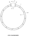
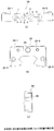
以下、本発明の実施形態例を図面に基づいて説明する。図1乃至図4は本発明に係る案内装置の構成を示す図で、図1は平面図、図2は図1のA−A断面図、図3は通常の側蓋の正面図、図4は移動ブロックの平面図である。図示するように、本案内装置は無端で環状の軌道レール1に、移動ブロック2が移動自在に組み付けられた構成である。軌道レール1は軸方向(移動ブロック2の移動方向)に直交する断面が略矩形状で、その左右両側中央部に凹部が形成されて上部左右に突条11、12が形成された形状である。突条11の上下角部には転動体(ここではボール)転走溝11−1、11−2が形成され、突条12の上下角部には転動体転走溝12−1、12−2が形成されている。
Embodiments of the present invention will be described below with reference to the drawings. 1 to 4 are views showing the structure of a guide device according to the present invention. FIG. 1 is a plan view, FIG. 2 is a cross-sectional view taken along the line AA in FIG. 1, FIG. FIG. 3 is a plan view of a moving block. As shown in the figure, the present guide device has a structure in which a moving
移動ブロック2の本体である移動ブロック本体21は断面がコ字状で、その開口部を挟んで左右両側にスカート部22、23が形成された形状である。開口部の幅寸法(スカート部22の内側面とスカート部23の内側面の間隔)L1は軌道レール1の両突条11、12の先端間の幅寸法L2より大きく(L1>L2)なっている。即ち、移動ブロック本体21は軌道レール1の上方(側方)から組み込むことができるようになっている。また、移動ブロック本体21のスカート部22の内側面には軌道レール1の転動体転走溝11−1、11−2に対応して負荷転動体転走溝22−1、22−2が軸方向に設けられ、スカート部23の内側面には軌道レール1の転動体転走溝12−1、12−2に対応して負荷転動体転走溝23−1、23−2が軸方向に設けられている。また、スカート部22には負荷転動体転走溝22−1、22−2に対応して転動体逃げ孔22−3、22−4が設けられ、スカート部23には負荷転動体転走溝23−1、23−2に対応して転動体逃げ孔23−3、23−4が設けられている。
The moving block
軌道レール1の転動体転走溝11−1、11−2と移動ブロック本体21の負荷転動体転走溝22−1、22−2でそれぞれ負荷転動体転走路R1、R2が形成され、軌道レール1の転動体転走溝12−1、12−2と移動ブロック本体21の負荷転動体転走溝23−1、23−2でそれぞれ負荷転動体転走路R3、R4が形成される。移動ブロック本体21の移動方向(軸方向)両端に側蓋24、25が設けられ、該側蓋24、25にはそれぞれ負荷転動体転走路R1、R2の転動体(ボール)3を転動体逃げ孔22−3、22−4又はその反対に移動させるための方向転換路R5、R6、負荷転動体転走路R3、R4の転動体(ボール)3を転動体逃げ孔23−3、23−4又はその反対に移動させるための方向転換路R7、R8が設けられている。即ち、移動ブロック2の移動に伴なって多数の転動体(ボール)3は負荷転動体転走路R1、R2、R3、R4、転動体逃げ孔22−3、22−4、23−3、23−4及び方向転換路R5、R6、R7、R8で構成される転動体循環路(図では4本の転動体循環路を構成している)を転走循環する。
Loaded rolling element rolling paths R1 and R2 are formed by the rolling element rolling grooves 11-1 and 11-2 of the
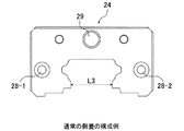
上記のように、移動ブロック本体21は開口部の幅寸法L1は軌道レール1の両突条11、12の先端間の幅寸法L2より大きく(L1>L2)なっているから、軌道レール1の上方(側方)から組み込むことができる。従って、軌道レール1が無端の環状形状でも組み込むことが容易である。これに対して、側蓋24、25は通常図3に示すような形状で、開口部の幅寸法L3が軌道レール1の両突条11、12の先端間の幅寸法L2より小さく(L2>L3)なっているから、軌道レール1の上方(側方)から組み込むことができない。そこで本発明では側蓋24、25も軌道レール1の上方から組み込むことができるように下記の改良を加えたものである。以下、側蓋24について説明するが、側蓋25も同様である。
As described above, since the width L1 of the opening of the moving block
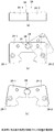
図5は側蓋24の構成例を示す図で、図5(a)は分解平面図、図5(b)は分解正面図、図5(c)は側面図である。図5において、図1乃至図4と同一符号を付した部分は同一又は相当部分を示す。なお、他の図においても同様とする。図示するように、側蓋24は正面形状が略コ字状でその開口部で幅方向に左右に分割した分割体24−1、24−2となっている。側蓋24の一方の分割体24−1の分割面aに突出する位置決め用ピン26を設けると共に、他方の分割体24−2の分割面bに該位置決め用ピン26が嵌入される位置決め用穴27を設け、更にそれぞれの分割体24−1、24−2に固定用ビス穴28−1、28−2を設けている。2つ分割体24−1、24−2を軌道レール1の両側からその分割面a、bを互いに接近させ位置決め用ピン26を位置決め用穴27に嵌入し且つ分割面aと分割面bを一致させて側蓋組立体とする。次に該側蓋組立体を各分割体24−1、24−2の固定用ビス穴28−1、28−2に固定用ビスを通して移動ブロック本体21の端部に取付け固定する。なお、29は油穴である。
FIGS. 5A and 5B are diagrams showing a configuration example of the
上記のように、側蓋24を構成する分割体24−1、24−2を軌道レール1の両側から互いに接近させ位置決め用ピン26を位置決め用穴27に嵌入し且つ分割面aと分割面bを一致させて側蓋組立体とするから、分割体24−1と分割体24−2は互いに高精度で位置決めされ、更にこの側蓋組立体を固定用ビス穴28−1、28−2に固定用ビスを通して移動ブロック本体21の端部に取付け固定するから、分割体24−1、24−2で構成されるので、高精度で位置決めし固定することができ、更に使用中に位置ずれが発生することもない。
As described above, the divided bodies 24-1 and 24-2 constituting the
図6は側蓋24の他の構成例を示す図で、図6(a)は平面図、図6(b)は正面図、図6(c)は側面図、図6(d)は位置決め用部材の正面図、図6(e)は位置決め用部材の平面図である。側蓋24は開口部で幅方向に左右に分割した分割体24−1、24−2で構成されている。両分割体24−1、24−2にはそれぞれ上面に分割面a、bから所定寸法離れた位置に位置決め用穴30−1、30−2を設けると共に、それぞれの分割体に固定用ビス穴28−1、28−2を設けている。31は金属板等からなる位置決め用部材であり、該位置決め用部材31はその両端部が位置決め用穴30−1、30−2に嵌入できるように、折り曲げ正面コ字状に形成されている。
FIG. 6 is a view showing another configuration example of the
分割体24−1、24−2を軌道レール1の両側から互いに接近させその分割面a、bが互いに当接し一致した状態で位置決め用部材31をその両端の折曲部を位置決め用穴30−1、30−2に嵌入して側蓋組立体とする。その後この側蓋組立体を固定用ビス穴28−1、28−2に固定用ビスを通して移動ブロック本体21の端部に取付け固定する。これにより上記実施例1の場合と同様、分割体24−1、24−2は高精度で位置決めされた状態で、移動ブロック本体21の端部に取付け固定されるので、使用中に位置ずれが発生することがない。なお、上記例では両分割体24−1、24−2の上面に位置決め用穴30−1、30−2を設け、位置決め用部材31を上から嵌入するように構成しているが、位置決め用穴30−1、30−2を分割体24−1、24−2の側面に設け、位置決め用部材31を側方から嵌入するように構成してもよい。
With the divided bodies 24-1 and 24-2 approaching each other from both sides of the
図7は側蓋24の他の構成例を示す図で、図7(a)は側蓋24と押え部材32の平面図、図7(b)は側蓋24の側面図、図7(c)は側蓋24の正面図、図7(d)は押え部材32の正面図である。側蓋24は開口部で幅方向に左右に分割した分割体24−1、24−2で構成されており、両分割体24−1、24−2にはそれぞれ固定用ビス穴28−1、28−2を設けている。また、押え部材32は金属板等からなり、両端部を折り曲げたコ字状としている。
FIG. 7 is a view showing another configuration example of the
分割体24−1、24−2を軌道レール1の両側から互いに接近させその分割面a、bを互いに当接させ且つ一致させた状態で、押え部材32の両端部間に嵌入することにより、両分割体24−1、24−2を互いに位置決めし、側蓋組立体とする。この状態で側蓋組立体を固定用ビス穴28−1、28−2に固定用ビスを通して移動ブロック本体21の端部に取付け固定する。これにより上記実施例1及び2と同様、分割体24−1、24−2は高精度で位置決めされた状態で、移動ブロック本体21の端部に取付け固定されるので、使用中に位置ずれが発生することがない。なお、上記例では押え部材32を側蓋組立体に正面側から嵌入することにしたが背面側から嵌入するようにしてもよく、更には上側から嵌入するようにしてもよい。
By fitting the divided bodies 24-1 and 24-2 from both sides of the
図8は側蓋24の他の構成例を示す図で、図8(a)は分解平面図、図8(b)は正面図、図8(c)は側面図である。側蓋24は軸方向(移動方向)面c、d、軸方向に直交する幅方向面eからなる分割面で左右に2分割した分割体24−1、24−2で構成されている。分割体24−1の軸方向面cと幅方向面eの交点に凹部f、軸方向面dと幅方向面eの交点に凸部gを設け、分割体24−2の軸方向面cと幅方向面eの交点に凹部fと嵌合する凸部h、軸方向面dと幅方向面eの交点に凸部gと嵌合する凹部iを設けている。そして分割体24−1、24−2を互いに軸方向面cとc、軸方向面dとd、幅方向面eとeを互いに当接させ且つ一致させた状態で凹部fと凸部h、凸部gと凹部iが嵌合して互いに幅方向の移動が規制された状態で位置決めされるようになっている。
8A and 8B are diagrams showing another configuration example of the
分割体24−1、24−2を軌道レール1の両側から互いに接近させ、互いに軸方向面cとc、dとd、幅方向面eとeを当接させ且つ一致させ、凹部fと凸部h、凸部gと凹部iを嵌合させて側蓋組立体とした状態で、該側蓋組立体を固定用ビス穴28−1、28−2に固定用ビスを通して移動ブロック本体21の端部に固定する。これにより上記実施例1乃至3と同様、分割体24−1、24−2は高精度で位置決めされた状態で、移動ブロック本体21の端部に取付け固定され、使用中に位置ずれが発生することがない。なお、側蓋24を分割して2つの分割体24−1、24−2とする面の組み合わせは上記例に限定されるものではなく、互いに面を当接させ一致させた状態で嵌合し、幅方向の移動を規制する凹凸部が形成される構成であればよい。
The divided bodies 24-1 and 24-2 are brought close to each other from both sides of the
図9は側蓋24の他の構成例を示す図で、図9(a)は正面図、図9(b)は一方の分割体の正面図、図9(c)は他方の分割体の正面図である。図9(a)に示すように、油穴29を形成した側蓋24を油穴29の中心から所定寸法離れた位置で且つ油穴29を横切る分割面jで側蓋24を2分割して、図9(b)、(c)に示すように分割体24−1、24−2とする。分割体24−2の油穴29に図9(d)に示すように円柱状の埋め栓33を挿入する。
FIG. 9 is a view showing another configuration example of the
分割体24−1、24−2を軌道レール1の両側から互いに分割面j、jを接近させ、分割体24−1の油穴29を分割体の埋め栓33に嵌合させて且つ分割面j、jを互いに一致させて側蓋組立体とする。この側蓋組立体を固定用ビス穴28−1、28−2に固定用ビスを通して移動ブロック本体21の端部に取付け固定する。これにより上記実施例1乃至4と同様、分割体24−1、24−2は高精度で位置決めされた状態で、移動ブロック本体21の端部に取付け固定されるので、使用中に位置ずれが発生することがない。
The divided bodies 24-1 and 24-2 are made to approach each other from both sides of the
上記実施例1乃至5では移動ブロック2が軌道レール1を跨いだ状態で組み込まれる構成の案内装置を例に説明したが、本発明はこのような構成の案内装置に限定されるものではなく、図10に示すように、断面コ字状の軌道レール1の開口部に移動ブロック2を組み込んだ構成の案内装置においても適用できる。即ちこのタイプの案内装置では、移動ブロック本体21自体は軌道レール1の上方から組み込むようにすることができるが、その移動方向両端に取り付ける側蓋の幅寸法は軌道レール1開口部の幅寸法L4より大きくなる。このような場合でも、図5乃至図9に示すように側蓋24を2つの分割体24−1、24−2に分割した構成の側蓋を用い、両分割体24−1、24−2を軌道レール1の開口部内で互いに位置を決めて側蓋組立体とした後、移動ブロック本体21の両端に取り付けるようにすれば、軌道レール1が無端環状の場合でも軌道レール1の中間で移動ブロックを容易に組み込むことができる。
In the first to fifth embodiments described above, the guide device having a configuration in which the moving
図11は本発明に係る案内装置の他の構成を示す平面図である。本案内装置は図示するように軌道レール1の転動体転走溝11−1、11−2(図示せず)及び転動体転走溝12−1、12−2(図示せず)が軌道レールの両端側で切れ上がっている。このような構成の案内装置では、通常の移動ブロック2を軌道レールの両端から組み込むことができない。そこで移動ブロック本体21は図2に示すように、軌道レール1の上方から組み込むことができるように構成し、側蓋24及び側蓋25を図5乃至図9に示すように側蓋24を2つの分割体24−1、24−2に分割した構成の側蓋を用いることにより、移動ブロック2を容易に軌道レール1に組み込むことができる。
FIG. 11 is a plan view showing another configuration of the guide device according to the present invention. As shown in the figure, the rolling guide rolling grooves 11-1 and 11-2 (not shown) and the rolling element rolling grooves 12-1 and 12-2 (not shown) of the
図12は側蓋24の他の構成例を示す図で、図12(a)は平面図、図12(b)は正面図、図12(c)は分割体を開いた状態を示す正面図である。図示するように、分割体24−1、24−2は開口部が幅方向に拡大できるよう一部が連結部34で互いに連結した分割体で構成されている。分割体24−1、24−2のそれぞれには固定用ビス穴28−1、28−2を設けている。連結部34はここを支点に分割体24−1、24−2を開口部を幅方向に回動させることができる弾力性を有している。
FIGS. 12A and 12B are diagrams showing another configuration example of the
側蓋24の分割体24−1、24−2を図12(c)に示すように連結部34を中心に時計及び反時計方向に回動させて開口部を拡大させた状態で軌道レール1を跨がせ、その後互いに接近させ側蓋組立体とし、固定用ビス穴28−1、28−2に固定用ビスを通して移動ブロック本体21の端部に固定する。これにより上記実施例1乃至6と同様、分割体24−1、24−2は高精度で位置決めされた状態で、移動ブロック本体21の端部に取付け固定されるので、使用中に位置ずれが発生することがない。
As shown in FIG. 12C, the divided rails 24-1 and 24-2 of the
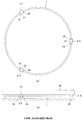
図13は本発明に係る案内装置の他の構成を示す図で、図13(a)は案内装置の平面図、図13(b)は案内装置を回転テーブルに用いた側面図である。本案内装置が図1の案内装置と異なる点は、図13(a)に示すように複数個(図では3個)の移動ブロック2−1〜2−3を環状の軌道レール1に移動自在に組み付けた点である。移動ブロック本体21は図2に示すものと同一構成のものを用い、その軸方向両端に取り付けた側蓋24、25には図5乃至図9、図12のいずれかに示すものと同一の構成の側蓋を用いている。
FIG. 13 is a diagram showing another configuration of the guide device according to the present invention. FIG. 13 (a) is a plan view of the guide device, and FIG. 13 (b) is a side view of the guide device used as a rotary table. 1 is different from the guide device of FIG. 1 in that a plurality of (three in the figure) moving blocks 2-1 to 2-3 can be moved to the
案内装置を上記のような構成にすることにより、移動ブロック2−1〜2−3上に図13(b)に示すようにテーブル35を搭載することにより、回転テーブルを構成できる。このような構成の回転テーブルは荷重点近くで荷重を受けることができるため、回転モーメントに強い回転テーブルとなる。 By configuring the guide device as described above, a rotating table can be configured by mounting the table 35 on the moving blocks 2-1 to 2-3 as shown in FIG. 13B. Since the rotary table having such a configuration can receive a load near the load point, the rotary table is strong against a rotational moment.
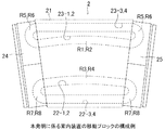
図14及び図15は本発明に係る案内装置の他の構成を示す図で、図14(a)は案内装置の平面図、図14(b)は同図(a)のB−B断面図、図15は図14(b)のC部分の拡大図である。本案内装置は無端で環状の軌道レール4の上側と下側にそれぞれ複数(図では3個)の移動ブロック5、6が移動自在に組み付けられた構成である。軌道レール4は軸方向(移動ブロックの移動方向)に直交する断面が略矩形状で、その左右両側中央部に凹部が形成されて上下部左右に突条41、42が形成された形状である。右側(内周側)上下の突条41、41には転動体(ここではボール)転走溝41−1、41−2が形成され、左側(外周側)上下の突条42には転動体転走溝42−1、42−2が形成されている。
14 and 15 are views showing another configuration of the guide device according to the present invention. FIG. 14 (a) is a plan view of the guide device, and FIG. 14 (b) is a cross-sectional view taken along line BB of FIG. 14 (a). FIG. 15 is an enlarged view of a portion C in FIG. This guide device has a configuration in which a plurality (three in the figure) of moving
移動ブロック5の本体である移動ブロック本体51は断面がコ字状で、その開口部を挟んで左右両側にスカート部52、53が形成された形状である。また、移動ブロック6の本体である移動ブロック本体61も断面がコ字状で、その開口部を挟んで左右両側にスカート部62、63が形成された形状である。移動ブロック本体51、61の開口部の幅寸法はいずれも軌道レール4の両突条41、42の先端間の幅寸法より大きくなっていて、移動ブロック本体51、61は軌道レール1の上方及び下方から組み込むことができるようになっている。
The moving block
また、移動ブロック本体51のスカート部52の内側面には軌道レール4の転動体転走溝41−1に対応して転動体転走溝52−1が軸方向に設けられ、スカート部53の内側面には軌道レール4の転動体転走溝42−1に対応して転動体転走溝53−1が軸方向に設けられている。また、移動ブロック本体61のスカート部62の内側面には軌道レール4の転動体転走溝41−2に対応して転動体転走溝62−1が軸方向に設けられ、スカート部63の内側面には軌道レール4の転動体転走溝42−2に対応して転動体転走溝63−1が軸方向に設けられている。また、移動ブロック本体51のスカート部52、53にはそれぞれ転動体転走溝52−1、53−1に対応して転動体逃げ孔52−2、53−2が設けられ、移動ブロック本体61のスカート部62には転動体転走溝62−1、63−1に対応して転動体逃げ孔62−2、63−2が設けられている。また移動ブロック本体5、6の軸方向(移動方向)両端に側蓋24’、25’が設けられている。該側蓋24’、25’には図5乃至図9、図12に示すものと略同じ構成の側蓋を用いている。
Further, on the inner side surface of the
また、図14及び図15に示す案内装置の側蓋24’、25’として図16に示す一体的に構成された側蓋24’を用いた場合、側蓋24’の開口部内側の転動体掬い部の突起部24’−1、24’−2の間隔寸法L6が軌道レール4の上端幅寸法L5(図15参照)より小さい(L6<L5)ため軌道レール4の上側から側蓋24’を組み込むことができない。そこで、側蓋24’を弾力性のある材料、例えば弾力性を有する樹脂材で構成する。そして図17に示すように、側蓋24’を軌道レール4の上側からその開口部に軌道レール4が入るように矢印Fに示すように押圧して挿入すると、側蓋24’は両突起部24−1、24−2が軌道レール4の上端部を通過する位置で、一点鎖線Eに示すように弾性変形した後、実線で示す位置に収まる。即ち側蓋24’を軌道レール4の上から挿入するとその転動体掬い部の突起24’−1、24’−2が軌道レール4の上端に当接し、更に押圧すると一点鎖線Eに示すように突起24’−1と24’−2の間隔が軌道レール4の上端が通る寸法(L5)に広がり、更に押圧すると、実線に示すように側蓋24’の突起24’−1、24’−2が軌道レール4の転動体転走溝41−1、42−1に収まり、側蓋24’が軌道レール4に組み込まれる。
Further, when the integrally configured side cover 24 ′ shown in FIG. 16 is used as the side covers 24 ′ and 25 ′ of the guide device shown in FIGS. 14 and 15, the rolling elements inside the opening of the
上記のように案内装置の側蓋24’を弾性を有する材料で構成し、開口部の最も幅寸法の小さい部分が弾性変形の範囲で広がり、軌道レール4の上端部を通すことができるようにすることにより、側蓋24’を容易に軌道レールに組み込むことができるようにする。これにより、図16に示すように、一体ものとして構成された側蓋24’、24’を、図17に示すように軌道レール4の上側及び下側に組み込むことが可能となる。なお、図17は図14(a)のD−D矢視断面拡大図である。また、図示は省略するが、側蓋25’、25’も同様に弾性を有する材料で構成することにより、軌道レール4の上側及び下側に組み込むことが可能となる。
As described above, the
図18は図14及び図15に示す構成の案内装置の使用例を示す図である。図示するように、軌道レール4の上下側に夫々複数の移動ブロック5、6を組み込んでなる案内装置70を台座81と台座82の間に介在させてロボット80を設置する。このように構成することにより、軌道レール4と台座82がそれぞれ独立して旋回できる。そのため軌道レール4にツールテーブル83等を取り付ければ、ロボット80のアームを旋回させることなく、ツール等を交換できる。また、ロボット80とツールテーブル83を互いに接近するように旋回させるとツール交換時間を短縮することもできる。
FIG. 18 is a diagram showing an example of use of the guide device having the configuration shown in FIGS. 14 and 15. As shown in the figure, a
本発明は上記実施例に制約されず種々の態様が可能である。例えば、転動体にボール3を用いる例を説明したが、転動体はボールに限定されるものではなく、ローラであってもよい。
The present invention is not limited to the above-described embodiments, and various modes are possible. For example, the example in which the
1 軌道レール
2 移動ブロック
3 転動体(ボール)
4 軌道レール
5 移動ブロック
6 移動ブロック
11 突条
12 突条
21 移動ブロック本体
22 スカート部
23 スカート部
24 側蓋
25 側蓋
24’ 側蓋
25’ 側蓋
26 位置決め用ピン
27 位置決め用穴
28 固定用ビス穴
29 油穴
30 位置決め用穴
31 位置決め用部材
32 押え部材
33 埋め栓
34 連結部
35 テーブル
51 移動ブロック本体
52 スカート部
53 スカート部
61 移動ブロック本体
62 スカート部
63 スカート部
70 案内装置
80 ロボット
81 台座
82 台座
83 ツールテーブル
1
DESCRIPTION OF
Claims (7)
前記軌道レールは無端で環状であり、直交する断面が矩形状でその左右両側に突条が形成され、該突条の上下に前記転動体転走面が形成された構成であり、
前記移動ブロック本体には軸方向直交断面の幅寸法が前記軌道レールの前記両突条の先端間の幅寸法より大きい開口部が設けられ、該移動ブロック本体を前記軌道レールに任意の位置で組み込み可能となっており、
前記側蓋は幅方向に左右に分割した分割体で構成され、
前記側蓋の両分割体をその分割面を対向させ前記軌道レールの両側から接近させ該両分割面を互いに当接一致させて位置決めし側蓋組立体とする連結手段を備え、
前記連結手段で側蓋組立体とし、該側蓋組立体を前記軌道レールに組み込んだ前記移動ブロック本体の相対移動方向両端に取付手段で取付け固定したことを特徴とする案内装置。 A moving block is mounted on a track rail having a rolling element rolling surface along the longitudinal direction so as to be relatively movable, and the moving block forms a load rolling element rolling path together with the rolling element rolling surface. A rolling element circulation path is formed together with a loaded rolling element rolling surface, a moving block body formed with a rolling element escape hole corresponding to the loaded rolling element rolling surface, and the loaded rolling element rolling path and the rolling element escape hole. A plurality of side lids that are formed with rolling element direction changing paths and attached to both ends of the moving block main body in the relative moving direction, and that circulate with the relative movement of the track rail and the moving block arranged in the rolling element circulation path. In a guide device provided with a rolling element of
The track rail has an endless annular shape, a rectangular cross section is rectangular, and protrusions are formed on both left and right sides thereof, and the rolling element rolling surfaces are formed above and below the protrusions,
The moving block main body is provided with an opening having a width dimension of an axially orthogonal cross section larger than the width dimension between the tips of the two protrusions of the track rail, and the moving block main body is assembled into the track rail at an arbitrary position. Is possible,
The side lid is composed of a divided body divided into left and right in the width direction,
The side cover is provided with connecting means for positioning the side lids so that the split surfaces face each other and approaching from both sides of the track rail so that the two split surfaces come into contact with and match each other.
A guide device characterized in that a side cover assembly is formed by the connecting means, and the side cover assembly is attached and fixed to both ends in the relative movement direction of the movable block main body incorporated in the track rail by attachment means .
前記連結手段は、前記側蓋の一方の分割体の分割面に突出する位置決め用ピンを設けると共に、他方の分割体の分割面に該位置決め用ピンが嵌入される位置決め用穴を設け、該位置決め用ピンを該位置決め用穴に嵌入して前記側蓋組立体とする構成であり、
前記取付手段は、前記側蓋組立体の各分割体に設けた固定用ビス穴に固定用ビスを通して前記側蓋組立体を前記移動ブロック本体の相対移動方向両端に取付け固定する構成であることを特徴とする案内装置。 The guide device according to claim 1, wherein
The connecting means is provided with a positioning pin that protrudes from a split surface of one divided body of the side lid, and a positioning hole into which the positioning pin is fitted in the split surface of the other split body, A pin for fitting into the positioning hole to form the side lid assembly,
The attachment means is configured to attach and fix the side cover assembly to both ends in the relative movement direction of the moving block body through fixing screws provided in fixing screw holes provided in each divided body of the side cover assembly. A characteristic guide device.
前記連結手段は、前記側蓋の両分割体に分割面から所定寸法離れた位置に位置決め用穴を設けると共に、両端部を該位置決め用穴に嵌入するように折り曲げたコ字状の位置決め用部材を具備し、該両分割体を互いに分割面が一致するように当接させ前記位置決め用部材の両端部を両分割体の位置決め用穴に嵌入して側蓋組立体とする構成であり、
前記取付手段は、前記側蓋組立体の各分割体に設けた固定用ビス穴に固定用ビスを通して前記側蓋組立体を前記移動ブロック本体の相対移動方向両端に取付け固定する構成であることを特徴とする案内装置。 The guide device according to claim 1, wherein
The connecting means has a U-shaped positioning member in which positioning holes are provided in positions separated from the dividing surface in both divided bodies of the side lid, and both end portions are bent so as to be fitted into the positioning holes. The two divided bodies are brought into contact with each other so that the divided surfaces coincide with each other, and both end portions of the positioning member are fitted into the positioning holes of both divided bodies to form a side lid assembly.
The attachment means is configured to attach and fix the side cover assembly to both ends in the relative movement direction of the moving block body through fixing screws provided in fixing screw holes provided in each divided body of the side cover assembly. A characteristic guide device.
前記連結手段は、両端部を折り曲げたコ字状の押え部材を具備し、該押え部材の両端部間に前記両分割体を互いに分割面が一致するように当接させ嵌入して側蓋組立体とする構成であり、
前記取付手段は、前記側蓋組立体の各分割体に設けた固定用ビス穴に固定用ビスを通して前記側蓋組立体を前記移動ブロック本体の相対移動方向両端に取付け固定する構成であることを特徴とする案内装置。 The guide device according to claim 1, wherein
The connecting means includes a U-shaped presser member having both ends bent, and the side cover assembly is fitted between the both ends of the presser member so that the two split bodies are brought into contact with each other so that the split surfaces coincide with each other. It is a configuration that is three-dimensional,
The attachment means is configured to attach and fix the side cover assembly to both ends in the relative movement direction of the moving block body through fixing screws provided in fixing screw holes provided in each divided body of the side cover assembly. A characteristic guide device.
前記連結手段は、前記側蓋の両分割体の分割面に互いに嵌合し幅方向の移動を規制する凹凸部を設けると共に、該両分割体を互いに分割面を一致させ且つ凹凸部を嵌合させて側蓋組立体とする構成であり、
前記取付手段は、前記側蓋組立体の各分割体に設けた固定用ビス穴に固定用ビスを通して前記側蓋組立体を前記移動ブロック本体の相対移動方向両端に取付け固定する構成であることを特徴とする案内装置。 The guide device according to claim 1, wherein
The connecting means is provided with an uneven portion that fits to the split surfaces of the two split bodies of the side lid and restricts movement in the width direction, and the split surfaces of the split bodies are matched to each other and the concave and convex portions are fitted to each other. The side lid assembly.
The attachment means is configured to attach and fix the side cover assembly to both ends in the relative movement direction of the moving block body through fixing screws provided in fixing screw holes provided in each divided body of the side cover assembly. A characteristic guide device.
前記連結手段は、前記側蓋の一方の分割体にその分割面に一部が露出する埋め栓を設けると共に、他方の分割体の分割面に該埋め栓の露出部が嵌合する凹部を設け、該両分割体を互いに分割面を一致させ且つ埋め栓の露出部を凹部に嵌合させて側蓋組立体とする構成であり、
前記取付手段は、前記側蓋組立体の各分割体に設けた固定用ビス穴に固定用ビスを通して前記側蓋組立体を前記移動ブロック本体の相対移動方向両端に取付け固定する構成であることを特徴とする案内装置。 The guide device according to claim 1, wherein
The connecting means is provided with a plug that is partially exposed on one of the divided surfaces of the side cover, and a recess that fits the exposed portion of the plug on the divided surface of the other divided body. , The two divided bodies are configured such that the divided surfaces coincide with each other and the exposed portion of the plug is fitted into the concave portion to form a side lid assembly,
The attachment means is configured to attach and fix the side cover assembly to both ends in the relative movement direction of the moving block body through fixing screws provided in fixing screw holes provided in each divided body of the side cover assembly. A characteristic guide device.
前記軌道レールは無端で環状であり、直交する断面がコ字状でその左右両内側面に上下方向に前記転動体転走面が形成された構成であり、
前記軌道レールは断面コ字状で、前記移動ブロックは該軌道レールの断面コ字状開口部に組み込んだ構成であり、
前記移動ブロック本体には軸方向直交断面の幅寸法が前記軌道レールの開口部の幅寸法より小さく、該移動ブロック本体を前記軌道レールの任意の位置で開口部に組み込み可能となっており、
前記側蓋は幅方向に左右に分割した分割体で構成され、
前記側蓋の両分割体を前記軌道レールの断面コ字状開口部内で両分割面を互いに当接一致させて位置決めし側蓋組立体とし、
前記側蓋組立体を前記軌道レールの開口部に組み込んだ前記移動ブロック本体の相対移動方向両端に取付け固定したことを特徴とする案内装置。 A moving block is mounted on a track rail having a rolling element rolling surface along the longitudinal direction so as to be relatively movable, and the moving block forms a load rolling element rolling path together with the rolling element rolling surface. A rolling element circulation path is formed together with a loaded rolling element rolling surface, a moving block body formed with a rolling element escape hole corresponding to the loaded rolling element rolling surface, and the loaded rolling element rolling path and the rolling element escape hole. A plurality of side lids that are formed with rolling element direction changing paths and attached to both ends of the moving block main body in the relative moving direction, and that circulate with the relative movement of the track rail and the moving block arranged in the rolling element circulation path. In a guide device provided with a rolling element of
The track rail is endless and annular, the cross section perpendicular to the U-shape and the rolling element rolling surface is formed in the vertical direction on both the left and right inner surfaces,
The track rail is U-shaped in cross section, and the moving block is configured to be incorporated in the U-shaped opening of the track rail,
The width dimension of the cross section in the axial direction orthogonal to the moving block body is smaller than the width dimension of the opening of the track rail, and the moving block body can be incorporated into the opening at an arbitrary position of the track rail.
The side lid is composed of a divided body divided into left and right in the width direction,
Positioning the divided parts of the side lid in such a manner that the two divided surfaces come into contact with each other within the U-shaped opening of the track rail,
A guide device characterized in that the side cover assembly is mounted and fixed at both ends in the relative movement direction of the moving block main body incorporated in the opening of the track rail .
Priority Applications (1)
| Application Number | Priority Date | Filing Date | Title |
|---|---|---|---|
| JP2003383004A JP4472967B2 (en) | 2003-11-12 | 2003-11-12 | Guide device |
Applications Claiming Priority (1)
| Application Number | Priority Date | Filing Date | Title |
|---|---|---|---|
| JP2003383004A JP4472967B2 (en) | 2003-11-12 | 2003-11-12 | Guide device |
Publications (2)
| Publication Number | Publication Date |
|---|---|
| JP2005147203A JP2005147203A (en) | 2005-06-09 |
| JP4472967B2 true JP4472967B2 (en) | 2010-06-02 |
Family
ID=34691899
Family Applications (1)
| Application Number | Title | Priority Date | Filing Date |
|---|---|---|---|
| JP2003383004A Expired - Lifetime JP4472967B2 (en) | 2003-11-12 | 2003-11-12 | Guide device |
Country Status (1)
| Country | Link |
|---|---|
| JP (1) | JP4472967B2 (en) |
Families Citing this family (5)
| Publication number | Priority date | Publication date | Assignee | Title |
|---|---|---|---|---|
| JP2008089102A (en) * | 2006-10-03 | 2008-04-17 | Kokoku Intech Co Ltd | Lubricant supply device and linear motion device equipped therewith |
| JP4964052B2 (en) * | 2007-07-23 | 2012-06-27 | Thk株式会社 | Swivel structure |
| WO2011030722A1 (en) * | 2009-09-10 | 2011-03-17 | Thk株式会社 | Track rail and movement guide device provided with the track rail |
| WO2011155416A1 (en) * | 2010-06-11 | 2011-12-15 | Thk株式会社 | Rotation structure, horizontal-shaft wind power generation device, and motion guide device |
| JP7240960B2 (en) * | 2019-06-07 | 2023-03-16 | 日本トムソン株式会社 | rolling guide unit |
-
2003
- 2003-11-12 JP JP2003383004A patent/JP4472967B2/en not_active Expired - Lifetime
Also Published As
| Publication number | Publication date |
|---|---|
| JP2005147203A (en) | 2005-06-09 |
Similar Documents
| Publication | Publication Date | Title |
|---|---|---|
| JP4004873B2 (en) | Guide device sealing device and guide device | |
| JP4564198B2 (en) | Linear motion guidance unit | |
| JP4472967B2 (en) | Guide device | |
| JPH10220470A (en) | Ball spline | |
| JP2007092898A (en) | Rolling element-storing belt for linear guide device and linear guide device | |
| JP2006046644A (en) | Recirculation linear ball bearing | |
| WO2013137085A1 (en) | Motion device | |
| TW201600743A (en) | Movement apparatus | |
| JP4500128B2 (en) | Linear motion guidance unit | |
| WO2006100735A1 (en) | Guide device | |
| JPH07243443A (en) | Direct acting rolling guide unit | |
| JP4295576B2 (en) | Linear motion guidance unit | |
| US7290647B2 (en) | Guide apparatus | |
| JP2006234032A (en) | Linear guide bearing device | |
| JP4657976B2 (en) | Linear motion guidance unit | |
| JP4635735B2 (en) | Linear motion guide bearing device | |
| JP2007309364A (en) | Linear guide device seal and linear guide device | |
| JP5851476B2 (en) | Rolling guide device | |
| JP2002106560A (en) | Temporary holding member in linear guide device | |
| JPH0540488Y2 (en) | ||
| JP2015075226A (en) | Mobile body holding tool, and mobile body | |
| JP2018501451A (en) | Exercise guidance device | |
| JPS636502Y2 (en) | ||
| JP4339187B2 (en) | Linear motion guidance unit | |
| JP2005337425A (en) | Linear moving guide unit |
Legal Events
| Date | Code | Title | Description |
|---|---|---|---|
| A521 | Request for written amendment filed |
Free format text: JAPANESE INTERMEDIATE CODE: A821 Effective date: 20061026 |
|
| A621 | Written request for application examination |
Free format text: JAPANESE INTERMEDIATE CODE: A621 Effective date: 20061026 |
|
| A131 | Notification of reasons for refusal |
Free format text: JAPANESE INTERMEDIATE CODE: A131 Effective date: 20090324 |
|
| A977 | Report on retrieval |
Free format text: JAPANESE INTERMEDIATE CODE: A971007 Effective date: 20090326 |
|
| A521 | Request for written amendment filed |
Free format text: JAPANESE INTERMEDIATE CODE: A523 Effective date: 20090525 Free format text: JAPANESE INTERMEDIATE CODE: A821 Effective date: 20090525 |
|
| A131 | Notification of reasons for refusal |
Free format text: JAPANESE INTERMEDIATE CODE: A131 Effective date: 20090908 |
|
| A521 | Request for written amendment filed |
Free format text: JAPANESE INTERMEDIATE CODE: A523 Effective date: 20091109 Free format text: JAPANESE INTERMEDIATE CODE: A821 Effective date: 20091109 |
|
| TRDD | Decision of grant or rejection written | ||
| A01 | Written decision to grant a patent or to grant a registration (utility model) |
Free format text: JAPANESE INTERMEDIATE CODE: A01 Effective date: 20100302 |
|
| A01 | Written decision to grant a patent or to grant a registration (utility model) |
Free format text: JAPANESE INTERMEDIATE CODE: A01 |
|
| A61 | First payment of annual fees (during grant procedure) |
Free format text: JAPANESE INTERMEDIATE CODE: A61 Effective date: 20100304 |
|
| FPAY | Renewal fee payment (event date is renewal date of database) |
Free format text: PAYMENT UNTIL: 20130312 Year of fee payment: 3 |
|
| R150 | Certificate of patent or registration of utility model |
Free format text: JAPANESE INTERMEDIATE CODE: R150 Ref document number: 4472967 Country of ref document: JP Free format text: JAPANESE INTERMEDIATE CODE: R150 |
|
| FPAY | Renewal fee payment (event date is renewal date of database) |
Free format text: PAYMENT UNTIL: 20130312 Year of fee payment: 3 |
|
| FPAY | Renewal fee payment (event date is renewal date of database) |
Free format text: PAYMENT UNTIL: 20140312 Year of fee payment: 4 |
|
| R250 | Receipt of annual fees |
Free format text: JAPANESE INTERMEDIATE CODE: R250 |
|
| R250 | Receipt of annual fees |
Free format text: JAPANESE INTERMEDIATE CODE: R250 |
|
| R250 | Receipt of annual fees |
Free format text: JAPANESE INTERMEDIATE CODE: R250 |
|
| R250 | Receipt of annual fees |
Free format text: JAPANESE INTERMEDIATE CODE: R250 |
|
| R250 | Receipt of annual fees |
Free format text: JAPANESE INTERMEDIATE CODE: R250 |
|
| R250 | Receipt of annual fees |
Free format text: JAPANESE INTERMEDIATE CODE: R250 |
|
| R250 | Receipt of annual fees |
Free format text: JAPANESE INTERMEDIATE CODE: R250 |
|
| R250 | Receipt of annual fees |
Free format text: JAPANESE INTERMEDIATE CODE: R250 |
|
| R250 | Receipt of annual fees |
Free format text: JAPANESE INTERMEDIATE CODE: R250 |
|
| R250 | Receipt of annual fees |
Free format text: JAPANESE INTERMEDIATE CODE: R250 |
|
| R250 | Receipt of annual fees |
Free format text: JAPANESE INTERMEDIATE CODE: R250 |
|
| EXPY | Cancellation because of completion of term |