JP4470954B2 - Vehicle driving force control device - Google Patents
Vehicle driving force control device Download PDFInfo
- Publication number
- JP4470954B2 JP4470954B2 JP2007069035A JP2007069035A JP4470954B2 JP 4470954 B2 JP4470954 B2 JP 4470954B2 JP 2007069035 A JP2007069035 A JP 2007069035A JP 2007069035 A JP2007069035 A JP 2007069035A JP 4470954 B2 JP4470954 B2 JP 4470954B2
- Authority
- JP
- Japan
- Prior art keywords
- input shaft
- rotational speed
- accelerator opening
- transmission
- transmission input
- Prior art date
- Legal status (The legal status is an assumption and is not a legal conclusion. Google has not performed a legal analysis and makes no representation as to the accuracy of the status listed.)
- Expired - Fee Related
Links
Images


Classifications
-
- F—MECHANICAL ENGINEERING; LIGHTING; HEATING; WEAPONS; BLASTING
- F02—COMBUSTION ENGINES; HOT-GAS OR COMBUSTION-PRODUCT ENGINE PLANTS
- F02D—CONTROLLING COMBUSTION ENGINES
- F02D29/00—Controlling engines, such controlling being peculiar to the devices driven thereby, the devices being other than parts or accessories essential to engine operation, e.g. controlling of engines by signals external thereto
- F02D29/02—Controlling engines, such controlling being peculiar to the devices driven thereby, the devices being other than parts or accessories essential to engine operation, e.g. controlling of engines by signals external thereto peculiar to engines driving vehicles; peculiar to engines driving variable pitch propellers
-
- B—PERFORMING OPERATIONS; TRANSPORTING
- B60—VEHICLES IN GENERAL
- B60W—CONJOINT CONTROL OF VEHICLE SUB-UNITS OF DIFFERENT TYPE OR DIFFERENT FUNCTION; CONTROL SYSTEMS SPECIALLY ADAPTED FOR HYBRID VEHICLES; ROAD VEHICLE DRIVE CONTROL SYSTEMS FOR PURPOSES NOT RELATED TO THE CONTROL OF A PARTICULAR SUB-UNIT
- B60W10/00—Conjoint control of vehicle sub-units of different type or different function
- B60W10/04—Conjoint control of vehicle sub-units of different type or different function including control of propulsion units
- B60W10/06—Conjoint control of vehicle sub-units of different type or different function including control of propulsion units including control of combustion engines
-
- B—PERFORMING OPERATIONS; TRANSPORTING
- B60—VEHICLES IN GENERAL
- B60W—CONJOINT CONTROL OF VEHICLE SUB-UNITS OF DIFFERENT TYPE OR DIFFERENT FUNCTION; CONTROL SYSTEMS SPECIALLY ADAPTED FOR HYBRID VEHICLES; ROAD VEHICLE DRIVE CONTROL SYSTEMS FOR PURPOSES NOT RELATED TO THE CONTROL OF A PARTICULAR SUB-UNIT
- B60W10/00—Conjoint control of vehicle sub-units of different type or different function
- B60W10/10—Conjoint control of vehicle sub-units of different type or different function including control of change-speed gearings
- B60W10/11—Stepped gearings
-
- B—PERFORMING OPERATIONS; TRANSPORTING
- B60—VEHICLES IN GENERAL
- B60W—CONJOINT CONTROL OF VEHICLE SUB-UNITS OF DIFFERENT TYPE OR DIFFERENT FUNCTION; CONTROL SYSTEMS SPECIALLY ADAPTED FOR HYBRID VEHICLES; ROAD VEHICLE DRIVE CONTROL SYSTEMS FOR PURPOSES NOT RELATED TO THE CONTROL OF A PARTICULAR SUB-UNIT
- B60W30/00—Purposes of road vehicle drive control systems not related to the control of a particular sub-unit, e.g. of systems using conjoint control of vehicle sub-units, or advanced driver assistance systems for ensuring comfort, stability and safety or drive control systems for propelling or retarding the vehicle
- B60W30/18—Propelling the vehicle
- B60W30/188—Controlling power parameters of the driveline, e.g. determining the required power
-
- B—PERFORMING OPERATIONS; TRANSPORTING
- B60—VEHICLES IN GENERAL
- B60W—CONJOINT CONTROL OF VEHICLE SUB-UNITS OF DIFFERENT TYPE OR DIFFERENT FUNCTION; CONTROL SYSTEMS SPECIALLY ADAPTED FOR HYBRID VEHICLES; ROAD VEHICLE DRIVE CONTROL SYSTEMS FOR PURPOSES NOT RELATED TO THE CONTROL OF A PARTICULAR SUB-UNIT
- B60W30/00—Purposes of road vehicle drive control systems not related to the control of a particular sub-unit, e.g. of systems using conjoint control of vehicle sub-units, or advanced driver assistance systems for ensuring comfort, stability and safety or drive control systems for propelling or retarding the vehicle
- B60W30/18—Propelling the vehicle
- B60W30/19—Improvement of gear change, e.g. by synchronisation or smoothing gear shift
-
- F—MECHANICAL ENGINEERING; LIGHTING; HEATING; WEAPONS; BLASTING
- F02—COMBUSTION ENGINES; HOT-GAS OR COMBUSTION-PRODUCT ENGINE PLANTS
- F02D—CONTROLLING COMBUSTION ENGINES
- F02D41/00—Electrical control of supply of combustible mixture or its constituents
- F02D41/02—Circuit arrangements for generating control signals
- F02D41/021—Introducing corrections for particular conditions exterior to the engine
- F02D41/0215—Introducing corrections for particular conditions exterior to the engine in relation with elements of the transmission
- F02D41/023—Introducing corrections for particular conditions exterior to the engine in relation with elements of the transmission in relation with the gear ratio shifting
-
- B—PERFORMING OPERATIONS; TRANSPORTING
- B60—VEHICLES IN GENERAL
- B60W—CONJOINT CONTROL OF VEHICLE SUB-UNITS OF DIFFERENT TYPE OR DIFFERENT FUNCTION; CONTROL SYSTEMS SPECIALLY ADAPTED FOR HYBRID VEHICLES; ROAD VEHICLE DRIVE CONTROL SYSTEMS FOR PURPOSES NOT RELATED TO THE CONTROL OF A PARTICULAR SUB-UNIT
- B60W2510/00—Input parameters relating to a particular sub-units
- B60W2510/10—Change speed gearings
- B60W2510/1015—Input shaft speed, e.g. turbine speed
-
- B—PERFORMING OPERATIONS; TRANSPORTING
- B60—VEHICLES IN GENERAL
- B60W—CONJOINT CONTROL OF VEHICLE SUB-UNITS OF DIFFERENT TYPE OR DIFFERENT FUNCTION; CONTROL SYSTEMS SPECIALLY ADAPTED FOR HYBRID VEHICLES; ROAD VEHICLE DRIVE CONTROL SYSTEMS FOR PURPOSES NOT RELATED TO THE CONTROL OF A PARTICULAR SUB-UNIT
- B60W2540/00—Input parameters relating to occupants
- B60W2540/10—Accelerator pedal position
- B60W2540/103—Accelerator thresholds, e.g. kickdown
-
- B—PERFORMING OPERATIONS; TRANSPORTING
- B60—VEHICLES IN GENERAL
- B60W—CONJOINT CONTROL OF VEHICLE SUB-UNITS OF DIFFERENT TYPE OR DIFFERENT FUNCTION; CONTROL SYSTEMS SPECIALLY ADAPTED FOR HYBRID VEHICLES; ROAD VEHICLE DRIVE CONTROL SYSTEMS FOR PURPOSES NOT RELATED TO THE CONTROL OF A PARTICULAR SUB-UNIT
- B60W2710/00—Output or target parameters relating to a particular sub-units
- B60W2710/06—Combustion engines, Gas turbines
- B60W2710/0677—Engine power
-
- B—PERFORMING OPERATIONS; TRANSPORTING
- B60—VEHICLES IN GENERAL
- B60W—CONJOINT CONTROL OF VEHICLE SUB-UNITS OF DIFFERENT TYPE OR DIFFERENT FUNCTION; CONTROL SYSTEMS SPECIALLY ADAPTED FOR HYBRID VEHICLES; ROAD VEHICLE DRIVE CONTROL SYSTEMS FOR PURPOSES NOT RELATED TO THE CONTROL OF A PARTICULAR SUB-UNIT
- B60W2710/00—Output or target parameters relating to a particular sub-units
- B60W2710/10—Change speed gearings
- B60W2710/1061—Output power
-
- F—MECHANICAL ENGINEERING; LIGHTING; HEATING; WEAPONS; BLASTING
- F02—COMBUSTION ENGINES; HOT-GAS OR COMBUSTION-PRODUCT ENGINE PLANTS
- F02D—CONTROLLING COMBUSTION ENGINES
- F02D2250/00—Engine control related to specific problems or objectives
- F02D2250/18—Control of the engine output torque
- F02D2250/21—Control of the engine output torque during a transition between engine operation modes or states
-
- F—MECHANICAL ENGINEERING; LIGHTING; HEATING; WEAPONS; BLASTING
- F02—COMBUSTION ENGINES; HOT-GAS OR COMBUSTION-PRODUCT ENGINE PLANTS
- F02D—CONTROLLING COMBUSTION ENGINES
- F02D41/00—Electrical control of supply of combustible mixture or its constituents
- F02D41/02—Circuit arrangements for generating control signals
- F02D41/04—Introducing corrections for particular operating conditions
- F02D41/10—Introducing corrections for particular operating conditions for acceleration
-
- F—MECHANICAL ENGINEERING; LIGHTING; HEATING; WEAPONS; BLASTING
- F16—ENGINEERING ELEMENTS AND UNITS; GENERAL MEASURES FOR PRODUCING AND MAINTAINING EFFECTIVE FUNCTIONING OF MACHINES OR INSTALLATIONS; THERMAL INSULATION IN GENERAL
- F16H—GEARING
- F16H59/00—Control inputs to control units of change-speed-, or reversing-gearings for conveying rotary motion
- F16H59/14—Inputs being a function of torque or torque demand
- F16H59/18—Inputs being a function of torque or torque demand dependent on the position of the accelerator pedal
-
- F—MECHANICAL ENGINEERING; LIGHTING; HEATING; WEAPONS; BLASTING
- F16—ENGINEERING ELEMENTS AND UNITS; GENERAL MEASURES FOR PRODUCING AND MAINTAINING EFFECTIVE FUNCTIONING OF MACHINES OR INSTALLATIONS; THERMAL INSULATION IN GENERAL
- F16H—GEARING
- F16H59/00—Control inputs to control units of change-speed-, or reversing-gearings for conveying rotary motion
- F16H59/36—Inputs being a function of speed
- F16H59/38—Inputs being a function of speed of gearing elements
- F16H59/42—Input shaft speed
-
- F—MECHANICAL ENGINEERING; LIGHTING; HEATING; WEAPONS; BLASTING
- F16—ENGINEERING ELEMENTS AND UNITS; GENERAL MEASURES FOR PRODUCING AND MAINTAINING EFFECTIVE FUNCTIONING OF MACHINES OR INSTALLATIONS; THERMAL INSULATION IN GENERAL
- F16H—GEARING
- F16H63/00—Control outputs from the control unit to change-speed- or reversing-gearings for conveying rotary motion or to other devices than the final output mechanism
- F16H63/40—Control outputs from the control unit to change-speed- or reversing-gearings for conveying rotary motion or to other devices than the final output mechanism comprising signals other than signals for actuating the final output mechanisms
- F16H63/50—Signals to an engine or motor
- F16H63/502—Signals to an engine or motor for smoothing gear shifts
Description
本発明は、内燃機関とトルクコンバータと変速機を搭載した車両において、運転者の出力要求に対して内燃機関及び変速機を制御することで車両の出力制御を行う車両の駆動力制御装置に関するものである。 The present invention relates to a vehicle driving force control device for controlling vehicle output by controlling an internal combustion engine and a transmission in response to a driver's output request in a vehicle equipped with an internal combustion engine, a torque converter, and a transmission. It is.
車両の駆動力制御において、一般的に、運転者のアクセルペダルを踏み込むことで変化するアクセル開度に基づいて、この運転者が要求する目標(要求)トルクを求め、この目標トルクに応じてエンジンのスロットル開度、燃料噴射量、点火時期などを制御するようにしている。一方、自動変速機を搭載した車両では、変速動作中のエンジントルクを一時的に低下させることで、この変速動作に伴う変速ショックを緩和するようにしたトルクダウン制御が行われている。このトルクダウン制御は、例えば、トルクダウン量とトルクダウンタイミングを演算し、トルクダウン要求量に対応する割合でエンジンの点火時期を遅らせることで、エンジンの出力トルクを低下させている。 In vehicle driving force control, in general, a target (requested) torque required by the driver is obtained based on an accelerator opening that changes as the driver depresses the accelerator pedal, and an engine is generated according to the target torque. The throttle opening, fuel injection amount, ignition timing, and the like are controlled. On the other hand, in a vehicle equipped with an automatic transmission, torque reduction control is performed so as to alleviate a shift shock associated with the shift operation by temporarily reducing the engine torque during the shift operation. In this torque-down control, for example, a torque-down amount and a torque-down timing are calculated, and the engine output torque is reduced by delaying the engine ignition timing at a rate corresponding to the torque-down request amount.
このようなエンジン及び自動変速機を搭載した車両の駆動力制御装置としては、例えば、下記特許文献1に記載されたものがある。
An example of a driving force control device for a vehicle equipped with such an engine and an automatic transmission is described in
この特許文献1に記載されたエンジン出力制御装置は、アクセルセンサの出力信号が調整部を経由してアクセル開度信号としてエンジンコントロールユニットに入力され、エンジンコントロールユニットは、このアクセル開度信号に基づいて電子制御スロットルバルブを作動させることでエンジンの出力状態を制御し、このとき、アクセルセンサの出力信号とアクセル開度信号の対応関係を、変速過程で調整部が一時的に変化させ、電子制御スロットルバルブのスロットル開度を所定幅だけ低下させることで、エンジンをトルクダウンさせ、自動変速機の変速過程での変速ショックを軽減するようにするものである。
In the engine output control device described in
上述した従来の車両のエンジン出力制御装置では、電子制御スロットルバルブを用い、エンジンコントロールユニットは、自動変速機の変速過程で、アクセルセンサの出力信号に対して、電子制御スロットルバルブのスロットル開度を所定幅だけ低下させることでエンジンをトルクダウンさせ、自動変速機の変速ショックを軽減している。この場合、エンジンコントロールユニットは、シフトクオリティが最良となるトルクダウン量を設定し、このトルクダウン量に見合うスロットル開度の変化量を算出し、電子制御スロットルバルブのスロットル開度を低下させている。 In the conventional vehicle engine output control device described above, an electronically controlled throttle valve is used, and the engine control unit controls the throttle opening of the electronically controlled throttle valve with respect to the output signal of the accelerator sensor during the shifting process of the automatic transmission. By reducing the torque by a predetermined width, the torque of the engine is reduced and the shift shock of the automatic transmission is reduced. In this case, the engine control unit sets the torque down amount that provides the best shift quality, calculates the amount of change in the throttle opening corresponding to this torque down amount, and reduces the throttle opening of the electronically controlled throttle valve. .
ところで、運転者がアクセルペダルを踏み込んで車両を加速させるとき、その運転状態に応じて要求する加速感が異なる。例えば、運転者は、駆動力差の少ない滑らかな加速感を望む場合がある一方、伸びのある加速感を望む場合もある。ところが、上述した従来のエンジン出力制御装置では、トルクダウン量に見合うスロットル開度を低下させることで、自動変速機の変速ショックを軽減している。有段式の自動変速機では、変速前後の変速比の変動が変速ギヤ段の切換えに伴って段階的に滑らかではないため、特に、伸びのある加速感を望むような車両の運転状態では、変速ショックの軽減と運転者が要求する加速感の両立が困難となってしまう。 By the way, when the driver depresses the accelerator pedal and accelerates the vehicle, the feeling of acceleration required according to the driving state is different. For example, the driver may desire a smooth acceleration feeling with a small driving force difference, and may desire an acceleration feeling with elongation. However, in the conventional engine output control device described above, the shift shock of the automatic transmission is reduced by reducing the throttle opening corresponding to the torque reduction amount. In a stepped automatic transmission, the change in the gear ratio before and after the shift is not smooth stepwise with the change of the shift gear stage. It is difficult to achieve both reduction of the shift shock and acceleration feeling required by the driver.
本発明は、このような問題を解決するためのものであって、運転者が要求する加速感を実現可能とすると共に変速ショックを軽減可能とする車両の駆動力制御装置を提供することを目的とする。 The present invention is intended to solve such a problem, and an object of the present invention is to provide a vehicle driving force control device that can realize the acceleration feeling required by the driver and reduce the shift shock. And
上述した課題を解決し、目的を達成するために、本発明の車両の駆動力制御装置は、内燃機関から変速機に入力する変速機入力軸回転数を検出する変速機入力軸回転数検出手段と、アクセル開度を検出するアクセル開度検出手段と、前記変速機入力軸回転数検出手段が検出した変速機入力軸回転数と前記アクセル開度検出手段が検出したアクセル開度に基づいて前記変速機の要求出力を算出する変速機要求出力算出手段と、該変速機要求出力算出手段が算出した要求出力に基づいて前記内燃機関及び前記変速機を制御する出力制御手段を具え、前記変速機要求出力算出手段は、前記アクセル開度検出手段が検出したアクセル開度が予め設定された所定値以下に維持されているとき、複数段の変速に渡って、前記アクセル開度ごとに前記変速機入力軸回転数検出手段が検出した変速機入力軸回転数に拘らず一定となる要求出力を設定する一方、前記アクセル開度検出手段が検出したアクセル開度が前記所定値より大きく維持されているとき、複数段の変速に渡って、前記アクセル開度と前記変速機入力軸回転数検出手段が検出した変速機入力軸回転数に基づいて、前記アクセル開度ごとに該変速機入力軸回転数の増減に伴って増減する要求出力を設定することを特徴とするものである。 In order to solve the above-described problems and achieve the object, a vehicle driving force control device according to the present invention includes a transmission input shaft rotational speed detection means for detecting a transmission input shaft rotational speed input from an internal combustion engine to a transmission. The accelerator opening detecting means for detecting the accelerator opening, the transmission input shaft rotational speed detected by the transmission input shaft rotational speed detecting means, and the accelerator opening detected by the accelerator opening detecting means. A transmission required output calculating means for calculating a required output of the transmission; and an output control means for controlling the internal combustion engine and the transmission based on the required output calculated by the transmission required output calculating means. required output calculating means, when the accelerator opening the accelerator opening detection means has detected is maintained below a predetermined value, over a shift of a plurality of stages, the transmission for each of the accelerator opening While the force shaft rotational speed detecting means sets the required output to be constant regardless to the transmission input shaft rotational speed detected accelerator opening the accelerator opening detection means has detected is maintained greater than the predetermined value when, over a shift of a plurality of stages, on the basis of the transmission input shaft speed the accelerator opening and the transmission input shaft rotational speed detecting means has detected, the speed-change transmission input shaft rotational speed for each of the accelerator opening A request output that increases / decreases with increase / decrease is set .
本発明の車両の駆動力制御装置では、前記変速機要求出力算出手段は、前記アクセル開度検出手段が検出したアクセル開度が予め設定された所定値以下のとき、前記変速機入力軸回転数検出手段が検出した変速機入力軸回転数が予め設定された所定の低回転領域にあると、この変速機入力軸回転数の増減に伴って要求出力を増減し、変速機入力軸回転数が前記低回転領域より高回転領域にあると、この変速機入力軸回転数に拘らず要求出力を一定値に設定することを特徴としている。 In the vehicle driving force control apparatus according to the present invention, the transmission required output calculation means is configured to change the transmission input shaft rotational speed when the accelerator opening detected by the accelerator opening detection means is equal to or less than a predetermined value set in advance. If the transmission input shaft rotational speed detected by the detection means is in a predetermined low rotational speed range, the required output is increased or decreased as the transmission input shaft rotational speed increases or decreases, and the transmission input shaft rotational speed is When the speed is higher than the low speed, the required output is set to a constant value regardless of the transmission input shaft speed.
本発明の車両の駆動力制御装置では、前記内燃機関と前記変速機との間にトルクコンバータが配置されており、前記変速機入力軸回転数検出手段は、前記内燃機関から前記トルクコンバータを介して前記変速機に入力する変速機入力軸回転数を検出することを特徴としている。 In the vehicle driving force control apparatus according to the present invention, a torque converter is disposed between the internal combustion engine and the transmission, and the transmission input shaft rotational speed detection means is connected from the internal combustion engine via the torque converter. And detecting the rotational speed of the transmission input shaft input to the transmission.
本発明の車両の駆動力制御装置によれば、変速機入力軸回転数とアクセル開度に基づいて変速機の要求出力を算出する変速機要求出力算出手段と、この要求出力に基づいて内燃機関及び変速機を制御する出力制御手段を設け、変速機要求出力算出手段は、アクセル開度が予め設定された所定値以下に維持されているとき、複数段の変速に渡ってアクセル開度ごとに変速機入力軸回転数に拘らず一定となる要求出力を設定する一方、アクセル開度が所定値より大きく維持されているとき、複数段の変速に渡ってアクセル開度と変速機入力軸回転数基づいて、アクセル開度ごとに変速機入力軸回転数の増減に伴って増減する要求出力を設定するので、アクセル開度が所定値以下のときは、要求出力を一定値に設定することで、変速前後に駆動力差の小さい滑らかな加速を実現することができ、アクセル開度が所定値より大きいときは、アクセル開度ごとに変速機入力軸回転数の増減に伴って増減する要求出力を設定することで、変速後の駆動力の落ち込みの小さい伸びのある加速を実現することができ、その結果、運転者が要求する加速感を実現可能とすると共に変速ショックを軽減可能とすることができる。 According to the vehicle driving force control apparatus of the present invention, a transmission request output calculating means for calculating a required output of the transmission based on the transmission input shaft rotation speed and the accelerator opening, and the internal combustion engine based on the required output And an output control means for controlling the transmission, wherein the transmission required output calculating means is provided for each accelerator opening over a plurality of speeds when the accelerator opening is maintained at a predetermined value or less. While the required output is set to be constant regardless of the transmission input shaft speed, when the accelerator opening is maintained larger than the predetermined value, the accelerator opening and the transmission input shaft speed are changed over multiple speeds. Based on the setting of the required output that increases or decreases with the increase or decrease of the transmission input shaft rotation speed for each accelerator opening, when the accelerator opening is below a predetermined value, by setting the required output to a constant value, Driving force difference before and after shifting It can be realized a small smooth acceleration when the accelerator opening is greater than a predetermined value, by setting the required output to increase or decrease with the transmission input shaft speed increase or decrease for each accelerator opening, after the shift Thus, it is possible to realize acceleration with a small drop in the driving force, and as a result, it is possible to realize the acceleration feeling required by the driver and to reduce the shift shock.
以下に、本発明に係る車両の駆動力制御装置の実施例を図面に基づいて詳細に説明する。なお、この実施例により本発明が限定されるものではない。 Embodiments of a vehicle driving force control apparatus according to the present invention will be described below in detail with reference to the drawings. In addition, this invention is not limited by this Example.
図1は、本発明の一実施例に係る車両の駆動力制御装置を表す概略構成図、図2は、アクセル開度に応じて設定された変速機入力軸回転数に対する要求出力を表すグラフ、図3は、本実施例の車両の駆動力制御装置における駆動力制御のフローチャート、図4は、アクセル開度が所定値以下のときの車両の駆動力変化を表すグラフ、図5は、アクセル開度が所定値より大きいときの車両の駆動力変化を表すグラフである。 FIG. 1 is a schematic configuration diagram showing a vehicle driving force control apparatus according to an embodiment of the present invention, and FIG. 2 is a graph showing a required output with respect to a transmission input shaft rotational speed set according to an accelerator opening degree. FIG. 3 is a flowchart of driving force control in the vehicle driving force control apparatus of the present embodiment, FIG. 4 is a graph showing changes in driving force of the vehicle when the accelerator opening is equal to or smaller than a predetermined value, and FIG. It is a graph showing the driving force change of a vehicle when a degree is larger than a predetermined value.
本実施例の車両の駆動力制御装置において、図1に示すように、内燃機関としてのエンジン11は水冷式直列4気筒エンジンであって、シリンダブロック上にシリンダヘッドが締結されて構成され、4つの気筒12が直列に形成されている。そして、この4つの気筒に図示しないピストンが昇降自在に嵌合し、この各ピストンは、コネクティングロッドを介してクランクシャフトが連結されている。
In the vehicle driving force control apparatus of the present embodiment, as shown in FIG. 1, an engine 11 as an internal combustion engine is a water-cooled in-line four-cylinder engine, and a cylinder head is fastened on a cylinder block. Two
燃焼室13は、シリンダブロック(気筒12)とシリンダヘッドとピストンにより区画されて構成されている。この燃焼室13に吸気ポート14及び排気ポート15が対向して連通するように形成されており、この吸気ポート14及び排気ポート15は、図示しない吸気弁及び排気弁により開閉自在となっている。従って、エンジンに同期して吸気カム及び排気カムが吸気弁及び排気弁を所定のタイミングで上下移動することで、吸気ポート14及び排気ポート15を開閉し、吸気ポート14と燃焼室13、燃焼室13と排気ポート15とをそれぞれ連通することができる。
The
各吸気ポート14には、吸気マニホールド16を介してサージタンク17が連結されている。一方、吸気管18の空気取入口にはエアクリーナ19が取付けられており、この吸気管18には、エアクリーナ19の下流側に位置してスロットル弁を有する電子スロットル装置20が設けられている。そして、この吸気管18の下流端部がサージタンク17に連結されている。
A surge tank 17 is connected to each
排気ポート15には、排気マニホールド21を介して排気管22が連結されており、この排気管22には、三元触媒23,24が装着されている。
An exhaust pipe 22 is connected to the
エンジン11には、吸気ポート14または燃焼室13に燃料を噴射するインジェクタ25が装着されると共に、燃焼室13に、混合気に対して点火する点火プラグ26が装着されている。
The engine 11 is equipped with an
車両には、エンジンコントロールユニット(ECU)27が搭載されており、このECU27は、インジェクタ25の燃料噴射タイミングや点火プラグ26の点火時期などを制御可能となっており、検出した吸入空気量、スロットル開度、エンジン回転数などのエンジン運転状態に基づいて燃料噴射量、噴射時期、点火時期などを決定している。即ち、吸気管18の上流側にはエアフローセンサ28が装着され、計測した吸入空気量をECU27に出力している。また、電子スロットル装置20にはスロットルポジションセンサ29が設けられ、現在のスロットル開度をECU27に出力している。更に、クランクシャフトにはクランク角センサ30が設けられ、検出したクランク角度をECU27に出力し、ECU27はクランク角度に基づいてエンジン回転数を算出する。また、シリンダブロックには水温センサ31が設けられており、検出したエンジン冷却水温をECU27に出力している。
The vehicle is equipped with an engine control unit (ECU) 27, which can control the fuel injection timing of the
このように構成されたエンジン11には、トルクコンバータ41を介して有段式の自動変速機42が連結されている。そして、自動変速機42にプロペラシャフト43が連結され、このプロペラシャフト43にデファレンシャルギア44を介して左右のドライブシャフト45が連結され、このドライブシャフト45に左右の駆動輪46が連結されている。
A stepped
従って、エンジン11が駆動すると、その駆動力がクランクシャフトから出力され、トルクコンバータ41を介して自動変速機42の入力軸に入力され、ここで所定の変速比に減速される。そして、減速後の駆動力が自動変速機42の出力軸からプロペラシャフト43に出力され、このプロペラシャフト43からデファレンシャルギア44を介して左右のドライブシャフト45に伝達され、左右の駆動輪46を駆動回転することができる。
Therefore, when the engine 11 is driven, the driving force is output from the crankshaft and input to the input shaft of the
この自動変速機42は、油圧制御装置47により油圧制御される。車両には、トランスミッションコントロールユニット(TCU)48が搭載されており、このTCU48は、油圧制御装置47を制御して自動変速機42を油圧制御することで、変速タイミングなどを制御可能となっている。即ち、自動変速機42には、入力軸回転数を検出する入力軸回転数センサ(変速機入力軸回転数検出手段)49が設けられており、検出した入力軸回転数をTCU48に出力している。また、アクセルペダルの踏み込み量に応じたアクセル回動を検出するアクセル開度センサ(アクセル開度検出手段)50が設けられており、検出したアクセル開度をTCU48に出力している。更に、TCU48には、運転者が操作するシフトレバー装置51が接続されており、パーキング(P)、リバース(R)、ニュートラル(N)、ドライブ(D)などの操作信号が入力される。
The
従って、ECU27とTCU48は、両者で車両の電子制御ユニット52として機能しており、相互間で情報の入出力を行っている。そのため、運転者によるアクセルペダルの踏み込み量に応じてエンジン11と自動変速機42を制御することで、車両の駆動力を制御している。
Accordingly, the
そして、本実施例の車両の駆動力制御装置では、入力軸回転数センサ49が検出した変速機入力軸回転数NTとアクセル開度センサ50が検出したアクセル開度PAPに基づいて自動変速機42(車両)の要求出力Pを算出する変速機要求出力算出手段と、この変速機要求出力算出手段が算出した要求出力Pに基づいてエンジン11及び自動変速機42を制御する出力制御手段を具えている。この場合、本実施例では、変速機要求出力算出手段は、TCU48が機能し、出力制御手段は、電子制御ユニット52(ECU27、TCU48)が機能する。
In the vehicle driving force control apparatus according to this embodiment, the
そして、TCU(変速機要求出力算出手段)48は、アクセル開度センサ50が検出したアクセル開度PAPが予め設定された所定値PAPs以下のとき、入力軸回転数センサ49が検出した変速機入力軸回転数NTに拘らず要求出力Pを一定値に設定する一方、アクセル開度センサ49が検出したアクセル開度PAPが所定値PAPsより大きいとき、入力軸回転数センサ49が検出した変速機入力軸回転数NTの増減に伴って要求出力Pを増減するようにしている。
A TCU (transmission request output calculation means) 48 transmits the transmission input detected by the input shaft
また、車両の駆動力を制御する場合、軸トルクを主体的に制御している。しかし、エンジン11と自動変速機42との間にトルクコンバータ41が介装されているとき、エンジン11のクランクシャフトの回転数と自動変速機42の入力軸回転数とは異なり、そのため、両者の軸トルクも異なり、駆動輪46の軸トルクとも異なる。そのため、本実施例では、運転者によるアクセルペダルの踏み込み量(アクセル開度PAP)に対して要求する物理パラメータを変速機入力軸回転数NTに応じた要求出力Pとして各種の計算を行う。この場合、出力=係数A×軸トルク×回転数で表される。
Further, when controlling the driving force of the vehicle, the shaft torque is controlled mainly. However, when the
即ち、運転者によるアクセルペダルの踏み込み量(アクセル開度)が小さいときは、滑らかな加速感を得たいものと推測することができ、運転者によるアクセルペダルの踏み込み量(アクセル開度)が大きいときは、伸びのある加速感を得たいものと推測することができる。運転者が感じる加速感のうち、滑らかな加速感とは、加速度が徐々に低下するものであり、伸びのある加速感とは、加速度がほぼ一定または徐々に大きくなる加速感である。 That is, when the amount of depression of the accelerator pedal (accelerator opening) by the driver is small, it can be assumed that a smooth acceleration feeling is desired, and the amount of depression of the accelerator pedal (accelerator opening) by the driver is large. Sometimes it can be speculated that one wants to gain a sense of acceleration. Of the acceleration feeling felt by the driver, the smooth acceleration feeling gradually decreases the acceleration, and the stretched acceleration feeling is an acceleration feeling in which the acceleration becomes substantially constant or gradually increases.
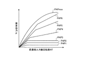
そこで、本実施例では、図2に示すように、変速機入力軸回転数NTに対する要求出力Pを設定するマップを作成し、これをアクセル開度ごとに設定する。そして、アクセル開度PAPが所定値PAPs以下のとき、例えば、PAP1〜PAP3の領域では、変速機入力軸回転数NTに拘らず要求出力Pを一定値に設定する。一方、アクセル開度PAPが所定値PAPsより大きいとき、例えば、PAP4〜PAPmaxの領域では、変速機入力軸回転数NTの増減に伴って要求出力Pを増減するように設定する。 Therefore, in this embodiment, as shown in FIG. 2, a map for setting the required output P with respect to the transmission input shaft rotational speed NT is created and set for each accelerator opening. When the accelerator opening PAP is equal to or smaller than the predetermined value PAPs, for example, in the region of PAP1 to PAP3, the required output P is set to a constant value regardless of the transmission input shaft rotational speed NT. On the other hand, when the accelerator opening PAP is larger than the predetermined value PAPs, for example, in the region of PAP4 to PAPmax, the required output P is set to increase / decrease as the transmission input shaft rotational speed NT increases / decreases.
このアクセル開度PAPが所定値PAPs以下(PAP1〜PAP3の領域)にて、入力軸回転数センサ49が検出した変速機入力軸回転数NTが予め設定された所定の低回転領域にあるとき、変速機入力軸回転数NTの増減に伴って要求出力Pを増減し、変速機入力軸回転数NTが低回転領域より高回転領域にあるとき、この変速機入力軸回転数NTに拘らず要求出力Pを一定値に設定する。
When the accelerator opening PAP is equal to or less than a predetermined value PAPs (region of PAP1 to PAP3), the transmission input shaft rotational speed NT detected by the input shaft
なお、図2に示す変速機入力軸回転数NTに対する要求出力Pを設定するマップでは、最大アクセル開度PAPmax以下の領域で、6種類のアクセル開度PAP1〜PAP6のマップを設定したが、その数は、6種類に限定されるものではなく、それ以上またはそれ以下であってもよく、その間は、補間により求めればよい。また、このような三次元マップを用いずに、関数式を用いてアクセル開度PAPと変速機入力軸回転数NTから要求出力Pを算出してもよい。 In the map for setting the required output P for the transmission input shaft rotational speed NT shown in FIG. 2, maps of six types of accelerator openings PAP1 to PAP6 are set in the region below the maximum accelerator opening PAPmax. The number is not limited to six types, and may be more or less, and it may be obtained by interpolation in the meantime. Further, the required output P may be calculated from the accelerator opening PAP and the transmission input shaft speed NT using a function formula without using such a three-dimensional map.
従って、本実施例の車両の駆動力制御装置における駆動力制御にて、図3のフローチャートに示すように、ステップS11にて、TCU48は、入力軸回転数センサ49が検出した変速機入力軸回転数NTを読み込むと共に、アクセル開度センサ50が検出したアクセル開度PAPを読み込む。続いて、ステップS12にて、TCU48は、変速機入力軸回転数NTとアクセル開度PAPに基づいて、図2の三次元マップに基づいて自動変速機42(車両)の要求出力Pを算出する。
Accordingly, in the driving force control in the vehicle driving force control apparatus of this embodiment, as shown in the flowchart of FIG. 3, in step S11, the
そして、ステップS13にて、電子制御ユニット52は、この要求出力Pに基づいてエンジン11及び自動変速機42の駆動力を制御する。即ち、ECU27は、吸入空気量、スロットル開度、エンジン回転数などのエンジン運転状態に基づいて燃料噴射量、噴射時期、点火時期などを決定し、インジェクタ25及び点火プラグ26を制御し、TCU48は、エンジン運転状態に基づいて変速段、変速タイミングを決定し、油圧制御装置47を制御する。
In step S13, the
このとき、アクセル開度センサ50が検出したアクセル開度PAPが所定値PAPs以下のときは、変速機入力軸回転数NTに拘らず要求出力Pを一定値に設定する。そのため、車両の加速度が徐々に低下することとなり、自動変速機42の変速前後に駆動力差の小さい滑らかな加速を実現することができる。一方、アクセル開度センサ49が検出したアクセル開度PAPが所定値PAPsより大きいときは、変速機入力軸回転数NTの増減に伴って要求出力Pを増減するように設定する。そのため、車両の加速度がほぼ一定(または徐々に大きく)となり、自動変速機42の変速後の駆動力の落ち込みの小さい伸びのある加速を実現することができる。
At this time, when the accelerator opening PAP detected by the
ここで、アクセル開度センサ50が検出したアクセル開度PAPが所定値PAPs以下の場合と、アクセル開度センサ50が検出したアクセル開度PAPが所定値PAPsより大きい場合とのおける車両の駆動力変化について詳細に説明する。
Here, the driving force of the vehicle when the accelerator opening PAP detected by the
図4に示すように、運転者がアクセルペダルを踏み込んで、所定値のアクセル開度PAPs以下で一定に維持したとき、このときのアクセル開度PAPごとに変速機入力軸回転数NTに拘らず一定となる要求出力Pを設定する。すると、自動変速機42にて、変速機入力軸回転数NTの増加に応じて1速−2速−3速と変速が実行されることで、車速Vが増加する一方、加速度Gは徐々に低下していく。従って、自動変速機42による変速前後における加速度Gの差が0となり、車両は、駆動力差の小さい滑らかな加速を実現することができる。
As shown in FIG. 4, when the driver depresses the accelerator pedal and keeps it constant below the predetermined accelerator opening PAPs, the accelerator input PAP at this time is independent of the transmission input shaft rotational speed NT . A constant required output P is set. Then, in the
一方、図5に示すように、運転者がアクセルペダルを踏み込んで、所定値のアクセル開度PAPsより大きいアクセル開度PAPで一定に維持したとき、このときのアクセル開度PAPと変速機入力軸回転数NTに基づいて、変速機入力軸回転数NTの増減に伴って増減する要求出力Pを設定する。すると、自動変速機42にて、変速機入力軸回転数NTの増加に応じて1速−2速−3速と変速が実行されることで、車速Vが増加するとき、加速度Gは若干の落ち込みをもってほぼ一定となる。従って、自動変速機42による変速前後における加速度Gに差が発生するものの、各ギヤ段で出力が上昇する特性となるため、結果として、変速時における加速度Gの落ち込みが小さくなり、伸びのある加速を実現することができる。
On the other hand, as shown in FIG. 5, when the driver depresses the accelerator pedal and is kept constant at the accelerator opening PAP larger than the predetermined accelerator opening PAPs, the accelerator opening PAP and the transmission input shaft at this time are maintained. Based on the rotational speed NT, a required output P that increases and decreases as the transmission input shaft rotational speed NT increases and decreases is set. Then, in the
このように本実施例の車両の駆動力制御装置にあっては、エンジン11から自動変速機42に入力する変速機入力軸回転数を検出する入力軸回転数センサ49と、アクセル開度を検出するアクセル開度センサ50と、入力軸回転数センサ49が検出した変速機入力軸回転数とアクセル開度センサ50が検出したアクセル開度に基づいて自動変速機42の要求出力を算出するTCU48と、この要求出力に基づいてエンジン11及び自動変速機42を制御する電子制御ユニット52を設け、TCU48は、アクセル開度が所定値以下のとき、変速機入力軸回転数に拘らず要求出力を一定値に設定する一方、アクセル開度が所定値より大きいとき、変速機入力軸回転数の増減に伴って要求出力を増減するように設定している。
As described above, in the vehicle driving force control apparatus according to this embodiment, the input shaft
従って、アクセル開度が所定値以下のときは、要求出力を一定値に設定することで、自動変速機42における変速前後に駆動力差を小さくして滑らかな加速を実現することができ、アクセル開度が所定値より大きいときは、変速機入力軸回転数の増減に伴って要求出力を増減することで、自動変速機42における変速後の駆動力の落ち込みを小さくして伸びのある加速を実現することができ、その結果、運転者が要求する加速感を実現可能とすると共に変速ショックを軽減可能とすることができる。
Therefore, when the accelerator opening is equal to or smaller than the predetermined value, the required output is set to a constant value, so that the driving force difference before and after the shift in the
また、本実施例の駆動力制御装置では、TCU48は、アクセル開度が予め設定された所定値以下のとき、変速機入力軸回転数が予め設定された所定の低回転領域にあると、この変速機入力軸回転数の増減に伴って要求出力を増減し、変速機入力軸回転数が低回転領域より高回転領域にあると、この変速機入力軸回転数に拘らず要求出力を一定値に設定している。従って、運転者によるアクセル踏み込み度合に応じた要求出力を設定することができ、自動変速機42における変速前後に駆動力差を小さくして滑らかな加速を実現することができる。
Further, in the driving force control apparatus of the present embodiment, when the accelerator opening is equal to or less than a predetermined value set in advance, the
また、本実施例の駆動力制御装置では、エンジン11と自動変速機42との間にトルクコンバータ41を配置し、入力軸回転数センサ49は、エンジン11からトルクコンバータ41を介して自動変速機42に入力する変速機入力軸回転数を検出するようにしており、アクセル開度に対して要求する物理パラメータを、変速機入力軸回転数に応じた要求出力としている。従って、要求出力は、エンジン11の出力側、自動変速機42の入力側及び出力側、駆動輪46側で同等となることから、変速(トルクコンバータ41)による軸トルクの変化を演算する処理が不要となり、制御の簡素化を可能とすることができる。
In the driving force control apparatus of this embodiment, the
以上のように、本発明に係る車両の駆動力制御装置は、運転者が要求する加速感を実現可能とすると共に変速ショックを軽減可能とするものであり、いずれの車両に適用しても有用である。 As described above, the vehicle driving force control apparatus according to the present invention can realize the acceleration feeling required by the driver and reduce the shift shock, and is useful when applied to any vehicle. It is.
11 エンジン(内燃機関)
20 電子制御式スロットル装置
25 インジェクタ
26 点火プラグ
27 エンジンコントロールユニット、ECU
41 トルクコンバータ
42 自動変速機
47 油圧制御装置
48 トランスミッションコントロールユニット、TCU(変速機要求出力算出手段)
49 入力軸回転数センサ(変速機入力軸回転数検出手段)
50 アクセル開度センサ(アクセル開度検出手段)
52 電子制御ユニット(出力制御手段)
11 Engine (Internal combustion engine)
20 Electronically Controlled
41
49 Input shaft rotational speed sensor (transmission input shaft rotational speed detection means)
50 Accelerator position sensor (Accelerator position detector)
52 Electronic control unit (output control means)
Claims (3)
Priority Applications (5)
| Application Number | Priority Date | Filing Date | Title |
|---|---|---|---|
| JP2007069035A JP4470954B2 (en) | 2007-03-16 | 2007-03-16 | Vehicle driving force control device |
| CN2008800084550A CN101636576B (en) | 2007-03-16 | 2008-03-10 | Driving force controller of vehicle |
| PCT/JP2008/054318 WO2008114641A1 (en) | 2007-03-16 | 2008-03-10 | Driving force controller of vehicle |
| EP08721734A EP2123886B1 (en) | 2007-03-16 | 2008-03-10 | Driving force controller of vehicle |
| US12/525,829 US8112209B2 (en) | 2007-03-16 | 2008-03-10 | Vehicle driving force control device |
Applications Claiming Priority (1)
| Application Number | Priority Date | Filing Date | Title |
|---|---|---|---|
| JP2007069035A JP4470954B2 (en) | 2007-03-16 | 2007-03-16 | Vehicle driving force control device |
Publications (2)
| Publication Number | Publication Date |
|---|---|
| JP2008231952A JP2008231952A (en) | 2008-10-02 |
| JP4470954B2 true JP4470954B2 (en) | 2010-06-02 |
Family
ID=39765749
Family Applications (1)
| Application Number | Title | Priority Date | Filing Date |
|---|---|---|---|
| JP2007069035A Expired - Fee Related JP4470954B2 (en) | 2007-03-16 | 2007-03-16 | Vehicle driving force control device |
Country Status (5)
| Country | Link |
|---|---|
| US (1) | US8112209B2 (en) |
| EP (1) | EP2123886B1 (en) |
| JP (1) | JP4470954B2 (en) |
| CN (1) | CN101636576B (en) |
| WO (1) | WO2008114641A1 (en) |
Families Citing this family (5)
| Publication number | Priority date | Publication date | Assignee | Title |
|---|---|---|---|---|
| BR112013032748B1 (en) * | 2011-06-23 | 2020-12-29 | Toyota Jidosha Kabushiki Kaisha | vehicle traction control device |
| CN103006700B (en) * | 2011-09-20 | 2016-08-17 | 常州倍尔生生物科技有限公司 | PH buffer activity glass and its production and use |
| DE102016001399B4 (en) * | 2016-02-06 | 2020-09-17 | Audi Ag | Method and device for operating a drive device, drive device |
| CN111089681B (en) * | 2018-10-24 | 2020-12-08 | 广州汽车集团股份有限公司 | Method and device for estimating pressure in Miller engine cylinder |
| US11927168B2 (en) * | 2022-03-22 | 2024-03-12 | Ferrari S.P.A. | Method to control a road vehicle provided with an internal combustion engine during a gear shift |
Family Cites Families (16)
| Publication number | Priority date | Publication date | Assignee | Title |
|---|---|---|---|---|
| JPH09119328A (en) | 1995-10-26 | 1997-05-06 | Jatco Corp | Engine output controller |
| JP3539075B2 (en) * | 1996-06-14 | 2004-06-14 | トヨタ自動車株式会社 | Drive control device for hybrid vehicle |
| US6434466B1 (en) * | 1999-05-06 | 2002-08-13 | Ford Global Technologies, Inc. | System and method for determining engine torque for controlling a powertrain |
| US6371884B1 (en) * | 2000-05-19 | 2002-04-16 | Ford Global Technologies, Inc. | Constant power, part load control strategy for electronic engine controls |
| JP4538777B2 (en) | 2001-04-04 | 2010-09-08 | 株式会社デンソー | Control device for internal combustion engine |
| JP3915714B2 (en) * | 2003-02-28 | 2007-05-16 | マツダ株式会社 | Transmission control device |
| JP2005003193A (en) * | 2003-05-16 | 2005-01-06 | Toyota Motor Corp | Controller of lockup clutch for vehicle |
| US7101313B2 (en) | 2003-06-18 | 2006-09-05 | General Motors Corporation | Motor vehicle powertrain control method for low traction conditions |
| JP2005110469A (en) | 2003-10-02 | 2005-04-21 | Nissan Motor Co Ltd | Vehicle driving force controller |
| JP2005173972A (en) * | 2003-12-11 | 2005-06-30 | Obic Co Ltd | Register information acquisition system |
| JP4274100B2 (en) * | 2004-10-12 | 2009-06-03 | 日産自動車株式会社 | Engine control device |
| JP4525434B2 (en) * | 2005-04-13 | 2010-08-18 | トヨタ自動車株式会社 | Vehicle driving force control device |
| JP4642560B2 (en) * | 2005-06-14 | 2011-03-02 | アイシン・エィ・ダブリュ株式会社 | Hydraulic control device for automatic transmission |
| US7357754B2 (en) * | 2005-07-22 | 2008-04-15 | Gm Global Technology Operations, Inc. | Mechanism and method of controlling an automatic shifting power transmission to effect a first gear launch |
| JP2007064180A (en) * | 2005-09-02 | 2007-03-15 | Toyota Motor Corp | Control device for vehicle driving force |
| JP4337812B2 (en) * | 2005-12-21 | 2009-09-30 | トヨタ自動車株式会社 | Failure determination device for hydraulic control circuit |
-
2007
- 2007-03-16 JP JP2007069035A patent/JP4470954B2/en not_active Expired - Fee Related
-
2008
- 2008-03-10 CN CN2008800084550A patent/CN101636576B/en not_active Expired - Fee Related
- 2008-03-10 US US12/525,829 patent/US8112209B2/en not_active Expired - Fee Related
- 2008-03-10 WO PCT/JP2008/054318 patent/WO2008114641A1/en active Application Filing
- 2008-03-10 EP EP08721734A patent/EP2123886B1/en not_active Not-in-force
Also Published As
| Publication number | Publication date |
|---|---|
| EP2123886A4 (en) | 2011-09-28 |
| WO2008114641A1 (en) | 2008-09-25 |
| US8112209B2 (en) | 2012-02-07 |
| EP2123886A1 (en) | 2009-11-25 |
| JP2008231952A (en) | 2008-10-02 |
| CN101636576B (en) | 2012-12-05 |
| EP2123886B1 (en) | 2012-12-05 |
| US20100324789A1 (en) | 2010-12-23 |
| CN101636576A (en) | 2010-01-27 |
Similar Documents
| Publication | Publication Date | Title |
|---|---|---|
| US6991584B2 (en) | Control of powertrain smoothness using output torque sensing and input torque control | |
| US7258090B2 (en) | Intake air amount control apparatus for internal combustion engine | |
| JP2008121683A (en) | Control method for engine according to driver input and control system for vehicle | |
| US8301351B2 (en) | Gear shift system for vehicle, control method and control device for automatic transmission | |
| JP4179350B2 (en) | Vehicle control device | |
| JPH07208212A (en) | Intake air control system for variable displacement internal combustion engine | |
| JP4389877B2 (en) | Estimated torque calculation device for internal combustion engine mounted on vehicle | |
| JP4470954B2 (en) | Vehicle driving force control device | |
| JP5195932B2 (en) | Vehicle control apparatus and control method | |
| US20090024292A1 (en) | Vehicle controller and control method | |
| JP4379498B2 (en) | Drive source control apparatus and control method | |
| JP5267232B2 (en) | Shift control device | |
| JP5257393B2 (en) | Vehicle control device | |
| JP3914122B2 (en) | Ignition timing control device for internal combustion engine | |
| JP2862643B2 (en) | Control device for automatic transmission and engine | |
| JP6196042B2 (en) | Power unit controller | |
| JPH06144085A (en) | Integrated control system of engine and transmission | |
| JP4770812B2 (en) | Vehicle motion control device | |
| JP4591400B2 (en) | Engine idle state determination device | |
| JP2007255270A (en) | Controller of internal combustion engine | |
| US10099698B2 (en) | Control apparatus for vehicle and control method | |
| JP5930122B2 (en) | Control device and control method for internal combustion engine for vehicle | |
| JP2006046209A (en) | Controller for internal combustion engine | |
| JP5669596B2 (en) | Control device | |
| JP2013160162A (en) | Vehicle control unit |
Legal Events
| Date | Code | Title | Description |
|---|---|---|---|
| A621 | Written request for application examination |
Free format text: JAPANESE INTERMEDIATE CODE: A621 Effective date: 20080703 |
|
| A131 | Notification of reasons for refusal |
Free format text: JAPANESE INTERMEDIATE CODE: A131 Effective date: 20090908 |
|
| A521 | Written amendment |
Free format text: JAPANESE INTERMEDIATE CODE: A523 Effective date: 20091029 |
|
| A131 | Notification of reasons for refusal |
Free format text: JAPANESE INTERMEDIATE CODE: A131 Effective date: 20091124 |
|
| A521 | Written amendment |
Free format text: JAPANESE INTERMEDIATE CODE: A523 Effective date: 20100120 |
|
| TRDD | Decision of grant or rejection written | ||
| A01 | Written decision to grant a patent or to grant a registration (utility model) |
Free format text: JAPANESE INTERMEDIATE CODE: A01 Effective date: 20100209 |
|
| A01 | Written decision to grant a patent or to grant a registration (utility model) |
Free format text: JAPANESE INTERMEDIATE CODE: A01 |
|
| A61 | First payment of annual fees (during grant procedure) |
Free format text: JAPANESE INTERMEDIATE CODE: A61 Effective date: 20100222 |
|
| FPAY | Renewal fee payment (event date is renewal date of database) |
Free format text: PAYMENT UNTIL: 20130312 Year of fee payment: 3 |
|
| R151 | Written notification of patent or utility model registration |
Ref document number: 4470954 Country of ref document: JP Free format text: JAPANESE INTERMEDIATE CODE: R151 |
|
| FPAY | Renewal fee payment (event date is renewal date of database) |
Free format text: PAYMENT UNTIL: 20130312 Year of fee payment: 3 |
|
| FPAY | Renewal fee payment (event date is renewal date of database) |
Free format text: PAYMENT UNTIL: 20130312 Year of fee payment: 3 |
|
| FPAY | Renewal fee payment (event date is renewal date of database) |
Free format text: PAYMENT UNTIL: 20140312 Year of fee payment: 4 |
|
| LAPS | Cancellation because of no payment of annual fees |