JP4470356B2 - Game machine - Google Patents
Game machine Download PDFInfo
- Publication number
- JP4470356B2 JP4470356B2 JP2002021661A JP2002021661A JP4470356B2 JP 4470356 B2 JP4470356 B2 JP 4470356B2 JP 2002021661 A JP2002021661 A JP 2002021661A JP 2002021661 A JP2002021661 A JP 2002021661A JP 4470356 B2 JP4470356 B2 JP 4470356B2
- Authority
- JP
- Japan
- Prior art keywords
- game ball
- game
- gaming machine
- guide
- rolling
- Prior art date
- Legal status (The legal status is an assumption and is not a legal conclusion. Google has not performed a legal analysis and makes no representation as to the accuracy of the status listed.)
- Expired - Fee Related
Links
Images


Landscapes
- Pinball Game Machines (AREA)
Description
【0001】
【発明の属する技術分野】
本発明は、パチンコ機等の遊技機に関するものである。
【0002】
【従来の技術】
従来、遊技機の一種として、遊技盤に図柄表示装置等を備えたパチンコ機が知られている。このようなパチンコ機では、図柄表示装置の下方等に入賞装置等が設けられており、遊技球が入賞装置に入賞することに基づき、各種遊技状態、例えば遊技者に有利な大当たり状態等が導出される。
【0003】
図柄表示装置の周囲にはセンターパネルが設けられ、センターパネルには遊技球が転動可能なステージが設けられている。ステージに案内される遊技球は、しばらくステージ上で転動した後、遊技球の転動の仕方によっては、入賞手段へ入賞したりする。このため、遊技者は、ステージ上における遊技球の挙動に期待感を持って注目する。
【0004】
【発明が解決しようとする課題】
また、センターパネルには、遊技球をステージへ案内する遊技球流路いわゆるワープ流路と呼ばれる機構が設けられているものもある。ワープ流路は、遊技球の誘導性を高めるため、センターパネルの内部等において、その入口部から出口部までが筒状に形成されたものが多い。
【0005】
このため、ワープ流路を通過する遊技球が遊技者にとって視認困難となり、遊技者に対して不安感を抱かせるおそれがあるとともに、遊技球の挙動を楽しむ遊技者にとっては興趣が低減してしまうおそれがあった。
【0006】
本発明は、上述した問題に鑑みてなされたものであって、その目的は、遊技球の動きを見やすくし、興趣の飛躍的な向上を図ることのできる遊技機を提供することにある。
【0007】
【課題を解決するための手段】
上記の目的を達成するために有効な手段を以下に示す。なお、必要に応じてその作用等についても説明する。
本発明に係る遊技機は、
遊技球が流下可能な遊技領域において、識別情報を変動表示可能な可変表示装置の周囲を囲む特定遊技部材を備えるとともに、
前記特定遊技部材の下方に入賞手段を備え、
前記入賞手段に遊技球が入賞することに基づいて、前記可変表示装置にて前記識別情報が変動表示されるとともに、所定条件が成立した場合には特別遊技価値が付与される遊技機であって、
前記特定遊技部材は、
その下辺のフレーム部にて遊技球の転動を許容する転動遊技領域を備え、
前記転動遊技領域にて、遊技球を前記入賞手段のある下方へ落下させる傾斜面を備え、
前記可変表示装置の表示部を仕切る間仕切り部と、当該間仕切り部の前方に離間して設けられた案内レールとによって、遊技球の流下経路を形成し、
上辺のフレーム部を介して前記遊技領域から導入される遊技球を、左右のフレーム部から左右方向に離間した位置にて流下させつつ前記転動遊技領域へ誘導可能としたことをその要旨としている。
【0008】
【発明の実施の形態】
手段1.遊技球が流下可能な遊技領域において、前記遊技球を流下させつつ誘導する誘導手段を備え、
前記誘導手段は、少なくとも1つの誘導部材が前記遊技球を流下させる流下経路の周囲を囲むように配設された誘導流路であって、
前記流下経路の少なくとも一区間が開放されていることを特徴とする遊技機。
【0009】
上記手段1によれば、流下経路の少なくとも一区間が開放されているため、この開放部分を遊技者側に向けることによって、誘導される遊技球の動きが遊技者に視認可能となり、結果として、興趣の向上が図られる。また、開放部分より、球詰まりの解消作業、誘導手段(誘導流路)の清掃等を比較的容易に行うことができる。また、遊技者の視認しやすい部分が所定の透明部材によって構成され筒状となった誘導手段を備えた遊技機もあるが、このような遊技機に比べ、上記手段1の構成の遊技機では、所定の透明部材等を別途組み付けていないため、部材点数の削減、遊技機の構成又は組付け工程の簡素化等を図るとともに、さらなる視認性の向上を図ることができる。また、パチンコ機等の遊技機の前面側に配設されるガラス板等を誘導部材の1つとして利用することも考えられるが、このようにした場合、当該ガラス板等が破損したり傷ついたりして却って視認性を低下させるおそれがあり、誘導部材としてガラス板等を利用しない方がより好ましい。なお、前記流下経路は、前記遊技球が流下する道筋を指し示す。
【0010】
手段2.遊技球が流下可能な遊技領域において、前記遊技球を流下させつつ誘導する誘導手段を備え、
前記誘導手段は、前記遊技球を流下させる流下経路の周囲において、かつ、当該流下経路に沿って配設された複数の誘導部材によって構成されるとともに、
前記流下経路の少なくとも一区間が開放されていることを特徴とする遊技機。
【0011】
上記手段2によれば、流下経路の少なくとも一区間が開放されているため、この開放部分を遊技者側に向けることによって、誘導される遊技球の動きが遊技者に視認可能となり、結果として、興趣の向上が図られる。また、開放部分より、球詰まりの解消作業、誘導手段の清掃等を比較的容易に行うことができる。また、遊技者の視認しやすい部分が所定の透明部材によって構成され筒状となった誘導手段を備えた遊技機もあるが、このような遊技機に比べ、上記手段2の構成の遊技機では、所定の透明部材等を別途組み付けていないため、部材点数の削減、遊技機の構成又は組付け工程の簡素化等を図るとともに、さらなる視認性の向上を図ることができる。また、パチンコ機等の遊技機の前面側に配設されるガラス板等を誘導部材の1つとして利用することも考えられるが、このようにした場合、当該ガラス板等が破損したり傷ついたりして却って視認性を低下させるおそれがあり、誘導部材としてガラス板等を利用しない方がより好ましい。なお、前記流下経路は、前記遊技球が流下する道筋を指し示す。
【0012】
手段3.手段1又は手段2において、前記誘導手段は、前記流下経路の全区間又はほぼ全区間に沿って開放されていることを特徴とする遊技機。
【0013】
上記手段3によれば、より長い区間、遊技球の動きが遊技者に視認可能となり、さらなる興趣の向上につながる。
【0014】
手段4.手段1乃至手段3のいずれかにおいて、前記開放部分は、前記遊技領域の正面から当該遊技領域の略中央部にかけての所定範囲に向けて形成されていることを特徴とする遊技機。
【0015】
上記手段4によれば、前記開放部分が、遊技者がより遊技球を視認しやすい方向に向くこととなり、遊技球の視認性がより高まる。同様に、「前記開放部分の少なくとも一部が、前記遊技領域の正面から見て、視認可能となるように構成されていること」としてもよい。
【0016】
手段5.手段1乃至手段4のいずれかにおいて、前記開放部分は、前記遊技球の流下方向と略直交方向における開放幅が、前記遊技球の径より狭くなるよう構成されていることを特徴とする遊技機。
【0017】
上記手段5によれば、前記開放幅が遊技球の径より狭くなっているため、開放部分から遊技球が飛び出してしまう不具合を防止することができる。
【0018】
手段6.手段1乃至手段5のいずれかにおいて、前記流下経路の少なくとも一区間において、前記開放部分からの前記遊技球の飛び出しを規制する規制部を設けたことを特徴とする遊技機。
【0019】
上記手段6によれば、開放部分から遊技球が飛び出してしまう不具合を防止し、遊技球の誘導性をより高めることができる。なお、「前記規制部は、前記誘導手段と離間して設けられていること」としてもよいし、「前記規制部が、前記誘導部材に一体的に設けられていること」としもよい。誘導部材と一体的に設けることにより、部品点数の削減を図ることができる。また、「前記規制部が、前記流下経路の少なくとも一区間において、当該流下経路に沿って設けられていること」としてもよい。これにより、開放部分からの遊技球の飛び出しをより確実に防止することができ、より誘導性が高まる。
【0020】
手段7.遊技球が流下可能な遊技領域において、前記遊技球を流下させつつ誘導する誘導手段を備え、
前記誘導手段は、前記遊技球の流下経路の周囲において、かつ、当該流下経路に沿って配設された複数の誘導部材によって構成されるとともに、
前記複数の誘導部材のうちの少なくとも1つが他の前記誘導部材と離間した構成となっていることを特徴とする遊技機。
【0021】
上記手段7によれば、複数の誘導部材のうちの少なくとも1つが他の誘導部材と離間しているため、誘導手段には遊技球の流下経路の全域又はほぼ全域において隙間が生じることとなる。従って、この隙間(離間部分)を遊技者側に向けることによって、誘導される遊技球の動きが遊技者に視認可能となり、結果として、興趣の向上が図られる。また、離間部分より、球詰まりの解消作業、誘導手段の清掃等を比較的容易に行うことができる。また、遊技者の視認しやすい部分が所定の透明部材によって構成され筒状となった誘導手段を備えた遊技機もあるが、このような遊技機に比べ、上記手段7の構成の遊技機では、所定の透明部材等を別途組み付けていないため、部材点数の削減、遊技機の構成又は組付け工程の簡素化等を図るとともに、さらなる視認性の向上を図ることができる。また、パチンコ機等の遊技機の前面側に配設されるガラス板等を誘導部材の1つとして利用することも考えられるが、このようにした場合、当該ガラス板等が破損したり傷ついたりして却って視認性を低下させるおそれがあり、誘導部材としてガラス板等を利用しない方がより好ましい。なお、前記流下経路は、前記遊技球が流下する道筋を指し示す。
【0022】
手段8.手段7において、前記離間部分は、前記遊技領域の正面から当該遊技領域の略中央部の範囲内を向くように構成されていることを特徴とする遊技機。
【0023】
上記手段8によれば、前記離間部分が、遊技者がより遊技球を視認しやすい方向に向くこととなり、遊技球の視認性がより高まる。同様に、「前記離間部分の少なくとも一部が、前記遊技領域の正面から見て、視認可能となるように構成されていること」としてもよい。
【0024】
手段9.手段7又は手段8において、前記遊技球の流下方向と略直交方向における離間間隔が、前記遊技球の径より狭くなるよう構成されていることを特徴とする遊技機。
【0025】
上記手段9によれば、前記離間間隔が遊技球の径より狭くなっているため、離間部分から遊技球が飛び出してしまう不具合を防止することができる。
【0026】
手段10.手段7乃至手段9のいずれかにおいて、前記流下経路の少なくとも一区間において、前記離間部分からの前記遊技球の飛び出しを規制する規制部を設けたことを特徴とする遊技機。
【0027】
上記手段10によれば、離間部分から遊技球が飛び出してしまう不具合を防止し、遊技球の誘導性をより高めることができる。なお、「前記規制部が、前記誘導部材に一体的に設けられていること」としもよい。誘導部材と一体的に設けることにより、部品点数の削減を図ることができる。また、「前記規制部が、前記流下経路の少なくとも一区間において、当該流下経路に沿って設けられていること」としてもよい。これにより、離間部分からの遊技球の飛び出しをより確実に防止することができ、より誘導性が高まる。
【0028】
手段11.手段1乃至手段10のいずれかにおいては、前記複数の誘導部材のうちの少なくとも1つは、線状に延びる線状体により構成されていることを特徴とする遊技機。
【0029】
上記手段11によれば、誘導部材の少なくとも1つが線状体であることにより、前記誘導手段の隙間部分(開放部分)が増え、遊技球の視認性がより高まる。なお、前記線状体には、略直線状のもの、湾曲したものや蛇行したもの等が含まれる。
【0030】
手段12.手段1乃至手段11のいずれかにおいて、前記複数の誘導部材のうちの少なくとも1つは、所定壁面を有する板体により構成されていることを特徴とする遊技機。
【0031】
上記手段12によれば、誘導部材の少なくとも1つが所定壁面を有する板体であることにより、少なくとも当該遊技部材が設けられている部位においては、遊技球を規制する領域が増え、ひいては誘導性が高まる。なお、前記板体には、略直線状のもの、湾曲したものや蛇行したもの等が含まれる。
【0032】
手段13.手段12において、前記所定壁面には、前記遊技球の流下経路に沿った誘導溝が形成されていることを特徴とする遊技機。
【0033】
上記手段13によれば、誘導溝によって遊技球の誘導性がより高まる。なお、前記誘導溝を前記所定壁面より凹んだものとすれば、誘導部材の配置間隔をより狭くでき、誘導手段をよりコンパクトなものにすることができる。
【0034】
手段14.遊技球が流下可能な遊技領域において、前記遊技球を流下させつつ誘導する誘導手段を備え、
前記誘導手段は、前記遊技球の流下経路を挟んで相対向した一対の板体によって構成され、
前記両板体の対向間隔が前記遊技球の径より狭くなるように構成され、
前記両板体の対向面には、前記流通経路に沿った一対の誘導溝が形成され、
前記両誘導溝の底部同士の間隔が前記遊技球の径以上の広さとなるように構成されていることを特徴とする遊技機。
【0035】
上記手段14によれば、相対向した一対の板体に形成された誘導溝に沿って遊技球を誘導することができるため、誘導手段を流下経路に沿って開放させることができる。従って、この開放部分を遊技者側に向けることによって、誘導される遊技球の動きが遊技者に視認可能となり、結果として、興趣の向上が図られる。また、開放部分より、球詰まりの解消作業、誘導手段の清掃等を比較的容易に行うことができる。また、遊技者の視認しやすい部分が所定の透明部材によって構成され筒状となった誘導手段を備えた遊技機もあるが、このような遊技機に比べ、上記手段14の構成の遊技機では、所定の透明部材等を別途組み付けていないため、部材点数の削減、遊技機の構成又は組付け工程の簡素化等を図るとともに、さらなる視認性の向上を図ることができる。また、パチンコ機等の遊技機の前面側に配設されるガラス板等を誘導部材の1つとして利用することも考えられるが、このようにした場合、当該ガラス板等が破損したり傷ついたりして却って視認性を低下させるおそれがあり、誘導部材としてガラス板等を利用しない方がより好ましい。なお、前記流下経路は、前記遊技球が流下する道筋であって、特定の流路とは異なる。また、前記板体及び誘導溝の少なくとも一方には、略直線状のもの、湾曲したものや蛇行したもの等が含まれる。
【0036】
手段15.遊技球が流下可能な遊技領域において、前記遊技球を流下させつつ誘導する誘導手段を備え、
前記誘導手段は、前記遊技球の流下経路に沿って配設された板体と、
前記板体に沿って配設された複数の線状体とによって構成され、
前記板体と複数の線状体とがそれぞれ離間した構成であって、前記離間間隔が前記遊技球の径より狭くなるように構成されていることを特徴とする遊技機。
【0037】
上記手段15によれば、板体と複数の線状体に沿って遊技球を誘導することができるため、誘導部分の少なくとも一部を流下経路に沿って開放させることができる。従って、この開放部分を遊技者側に向けることによって、誘導される遊技球の動きが遊技者に視認可能となり、結果として、興趣の向上が図られる。また、開放部分より、球詰まりの解消作業、誘導手段の清掃等を比較的容易に行うことができる。また、遊技者の視認しやすい部分が所定の透明部材によって構成され筒状となった誘導手段を備えた遊技機もあるが、このような遊技機に比べ、上記手段15の構成の遊技機では、所定の透明部材等を別途組み付けていないため、部材点数の削減、遊技機の構成又は組付け工程の簡素化等を図るとともに、さらなる視認性の向上を図ることができる。また、パチンコ機等の遊技機の前面側に配設されるガラス板等を誘導部材の1つとして利用することも考えられるが、このようにした場合、当該ガラス板等が破損したり傷ついたりして却って視認性を低下させるおそれがあり、誘導部材としてガラス板等を利用しない方がより好ましい。なお、前記流下経路は、前記遊技球が流下する道筋であって、特定の流路とは異なる。また、前記板体及び線状体の少なくとも一方には、略直線状のもの、湾曲したものや蛇行したもの等が含まれる。
【0038】
手段16.手段1乃至手段15のいずれかにおいて、前記遊技領域に特定遊技部材を備え、当該特定遊技部材に前記遊技球の転動を許容する転動遊技領域を備え、
前記誘導手段は、前記特定遊技部材に一体的に設けられ、前記遊技領域を流下する前記遊技球を前記転動遊技領域へ誘導するよう構成されていることを特徴とする遊技機。
【0039】
手段17.手段16において、前記特定遊技部材は、識別情報を変動表示可能な可変表示装置の周囲を囲むセンターパネルによって構成されていることを特徴とする遊技機。
【0040】
手段18.手段1乃至手段17のいずれかにおいて、前記流下経路に沿って少なくとも1つの発光手段が配設され、
遊技者が前記誘導部材間を通して前記発光手段からの発光を視認できるように構成されていることを特徴とする遊技機。
【0041】
上記手段18によれば、遊技者は誘導手段の離間部分又は開放部分より発光を視認することができる。つまり、遊技者と発光手段との間に介在するものがなく又はより少ないため、発光手段による発光演出がより迫力のあるものとなる。また、遊技者に対して、発光手段の手前側を遊技球が通過していくため、発光演出と遊技球の動きによる演出がさらなる相乗効果を生みだし、さらなる興趣の向上が図られる。なお、前記発光手段は、前記誘導部材の一部に配設された構成としてもよいし、前記誘導手段と離間して配設された構成としてもよい。
【0042】
手段19.手段1乃至手段18のいずれかにおいて、前記遊技機はパチンコ機であること。中でも、パチンコ機の基本構成としては、操作ハンドルを備えておりそのハンドル操作に応じて遊技球を所定の遊技領域に発射させ、遊技球が遊技領域内の所定の位置に配置された入賞手段に入賞することに基づいて、特定条件が成立した場合には特別遊技価値が付与される。
【0043】
〔第1の実施の形態〕
以下、パチンコ遊技機(以下、単に「パチンコ機」という)の第1の実施の形態を図面に基づいて詳細に説明する。
【0044】
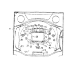
図1に示すように、パチンコ機は、遊技盤11を備えており、遊技盤11の前面にはほぼ垂直に配置された遊技領域としての遊技面12が形成されている。遊技盤11の中央には可変表示装置としての図柄表示装置13及び普通図柄表示装置16が組み込まれている。図柄表示装置13は液晶ディスプレイよりなる略長方形状の図柄表示部15を備えている。図柄表示部15を包囲するように特定遊技部材としてのセンターパネル17が配設されている。センターパネル17についてはさらに後述する。
【0045】
センターパネル17の下方には入賞手段としての作動口18が配設されている。作動口18の入口には一対の開閉羽根19が併設されており、遊技球を案内する開放位置と、作動口18内に遊技球が入りにくくなる閉塞位置をとりうる。作動口18への入賞に基づいて前記表示装置13が駆動され、図柄表示部15において識別情報としての図柄が表示される。開閉羽根19は遊技盤11の裏面側に配設された図示しないソレノイドによって駆動される。
【0046】
センターパネル17の両側方には一対の通過ゲート20が配置されている。前記作動口18の下方には大入賞口22が配置されている。大入賞口22は常時シャッタ23が閉塞されており、特定条件の成立に基づき特別遊技状態、いわゆる「大当たり」状態となると開放される。
【0047】
遊技盤11上には遊技面12を包囲するように電光装飾部25が配置されている。電光装飾部25は透明又は半透明の樹脂製パネルであって、パネル裏面にLEDよりなる図示しない装飾ランプが所定間隔で配置されている。
【0048】
本実施の形態では、内レール及び外レールは電光装飾部25内にて隠されており正面からは目視することができない。また、釘については図示が省略されている。遊技盤11の背面側には図柄表示装置13や賞球の排出等を制御する図示しない遊技機構が配設され、同遊技機構の下方には図示しない遊技球発射機構が配設されている。
【0049】
次に、センターパネル17について詳述する。図2に示すように、センターパネル17は前パネル27、フードパネル28及び背面パネル29を組み合わせて構成されている。図2及び図6に示すように、前パネル27は上方横方向に延出された横フレーム30を備え、該横フレーム30の左右端から下方に向かって、それぞれ下垂フレーム31が延出形成されている。左右の下垂フレーム31の内側面上部及び下部よりにはそれぞれ内側に湾曲された湾曲部32が形成されている。上下の湾曲部32の間には図6に示すように外方に凹んだ段違い部34が形成されている。これら上下の湾曲部32間に渡る下垂フレーム31の内側面及び段違い部34によって遊技球が転動する左右一対の第1転動面35が形成されている。従って、上下の湾曲部32及び段違い部34によって本実施の形態における一誘導部材又は所定壁面を有する板体が構成されている。図6及び図7に示すように、第1転動面35には遊技球の前方への飛び出しを防止するための規制部としての小レール35aが段違い部34を除く全域に渡って形成されている。
【0050】
図1、図2及び図4に示すように、前パネル27の横フレーム30の中央には透明窓30aが形成されている。透明窓30aの左右にはそれぞれ2つずつ半透明窓30bが形成されている。図2に示すように、横フレーム30の上端には遊技球を導入する導入口33が切り欠き形成されている。
【0051】
図1、図2、図4、図7及び図8に示すように、前パネル27には固定プレート39を介してフードパネル28が装着されている。フードパネル28は断面略長方形の筒形状の外観とされ、その後端は図柄表示部15の外形形状と合致する。フードパネル28は左右上下の側板28a〜28dによって構成され、左右側板28a,28bは前方ほど拡開され上下側板28c,28dは前方に向かって平行に延出されている。下側板28dには切れ込み37が形成されている。図6に示すように、フードパネル28の前端外周の左右寄り角部は湾曲した面取り部41とされ、上下の面取り部41間には図6に示すように外方に突出した略台形の突出部42が形成されている。これら上下の面取り部41間に渡るフードパネル28の外周面及び突出部42によって遊技球が転動する左右一対の第2転動面38が形成されている。従って、上下の面取り部41及び突出部42によって本実施の形態における一誘導部材又は所定壁面を有する板体が構成されている。図6及び図7に示すように、第2転動面38には遊技球の前方への飛び出しを防止するための規制部としての小レール38aが突出部42を除く全域に渡って形成されている。
【0052】
第1転動面35と第2転動面38との間隔は遊技球の径よりも若干幅広に形成されており、無理なく遊技球が通過することが可能な誘導手段又は誘導流路としての通路43とされている。この結果、第1転動面35と第2転動面38に挟まれた通路43が図柄表示部15の左右に配設されることとなる。通路43の途中には段違い部34と突出部42とにより屈曲部44が形成される。従って、通路43に沿った遊技球の経路が本実施の形態における流下経路に相当する。
【0053】
図2に示すように、屈曲部44の前面は固定プレート39にて覆われているため前方からの目視が妨げられるが、それ以外の通路43部分は開放されており、前方から遊技球が視認可能となる。ここで、小レール35a,38aの離間間隔(開放部分の幅)は遊技球の径よりも狭くなっている。
【0054】
図3及び図5に示すように、背面パネル29は基板45と該基板45の背面側に突出した沈埋部46とにより構成されている。背面パネル29は導電性樹脂としてのポリカーボネートベースの複合樹脂により構成されている。基板45前面には前記前パネル27が装着されている。基板45は通路43に対する後方壁となって、遊技球の後方への落下を防止する。つまり、基板45は一誘導部材を構成する。基板45の中央には大型の挿入孔48が形成され、該挿入孔48にはフードパネル28が挿入されている。
【0055】
挿入孔48の下方には転動遊技領域としての広場50が形成されている。広場50は後方ほど低くなるように、かつ中央ほど低くなるように傾斜が形成されている。また、中央には停滞した遊技球を下方へ落下させるための傾斜面51が形成されている。広場50の後方には防護壁52が装着されている。
【0056】
挿入孔48の周縁には沈埋部46の一部として後方に突出するフランジ53が形成されている。フランジ53は一部前記広場50の補強も兼ねている。図3及び図5に示すように、フランジ53の上方中央には沈埋部46の一部として第1案内通路55が後方に向かって突出形成されている。第1案内通路55は前記前パネル27の横フレーム30に形成された導出口33に接続されている。フランジ53の上方左右寄りには沈埋部46の一部として第2案内通路56が後方に向かって突出形成されている。第2案内通路56は前記通路43の上端位置に開口されている。図3及び図5に示すように、該両案内通路55,56には案内された遊技球を左右方向に導く傾斜通路57が連結されている。傾斜通路57は二股に分かれた桶構造の部材で、その中央最上端位置で第1案内通路55と接続され左右の最下端位置で第2案内通路56に接続されている。なお、図示しないが傾斜通路57の後方には遊技球の落下を防止する防止壁が形成されている。
【0057】
図4に示すように、挿入孔48の上方には略正方形の第1透孔48aと第1透孔48aの下方に4つ直列に配設された第2透孔48bと、第1透孔48aの左右にそれぞれ2つずつ配設された第3透孔48cが形成されている。第1透孔48aにはLEDよりなる7セグ表示部49が装着されている。第2透孔48bには発光ダイオード(LED)よりなる4つの第1保留ランプ16a〜16dが装着されている。第3透孔48cには第2保留ランプ15a〜15dが装着されている。
【0058】
第1保留ランプ16a〜16d及び7セグ表示部49は前記透明窓30aからそれらの点灯状態及びセグメント表示される数字が目視される。第2保留ランプ15a〜15dは4つの半透明窓30bからそれぞれ目視される。
【0059】
ここに、通過ゲート20を遊技球が通過すると前記普通図柄表示装置16が作動し、本実施の形態では「0」から「9」までの数字を可変表示して7セグ表示部49にセグメント表示させる。ここで所定の数字(本実施の形態では「7」)で停止した場合、作動口18の開閉羽根19を一定時間継続的に開放させる。普通図柄表示装置16は遊技球の通過ゲート20への通過回数を4回まで記憶することが出来、第1保留ランプ16a〜16dはその保留数を表示するためのものである。したがって、4つの第1保留ランプ16a〜16dが点灯している状態で遊技球が通過ゲート20を通過してもカウントされずに、第1保留ランプ16a〜16dが点灯している限り遊技球が通過ゲート20を通過しなくとも保留数に応じた回数だけ普通図柄表示装置16は作動する。
【0060】
また、上記のように図柄表示装置13は作動口18への入賞に基づいて駆動されて図柄表示部15に所定の図柄表示動作をさせる。このとき、図柄表示部15はその入賞を4回まで記憶することができ、第2保留ランプ15a〜15dはその保留数を表示するものである。従って、4つの第2保留ランプ15a〜15dが点灯している状態で、遊技球が作動口18に入賞してもカウントされず、第2保留ランプ15a〜15dが点灯している限り、遊技球が作動口18に入賞しなくとも保留数に応じた回数だけ図柄表示部15は図柄表示動作を行う。
【0061】
このように構成されたセンターパネル17は図7に示すように遊技面12と背面パネル29の基板45が面一となり、沈埋部46とフードパネル28の後部寄り約2/3が遊技面12よりも奥側に配置されることとなる。フードパネル28後端は同じく遊技面12から一段後退した位置に配設されている図柄表示部15に当接されている。
【0062】
次にこのように構成したパチンコ機の作用について説明する。図示しないハンドルを操作して遊技者は遊技球を遊技面12上に打ち出す。遊技球は釘に弾かれ或いは導かれて一部センターパネル17の導出口33からセンターパネル17内に導入される。導入された遊技球は第1案内通路55から後方の傾斜通路57に至り、ここでさらに左右に振り分けられて第2案内通路56から再び前方に送られる。そして、通路43を下降する。遊技球は第2案内通路56から前方に出現して通路43に至ってからは固定プレート39位置以外では遊技者から常に目視可能とされる。固定プレート39位置では屈曲部44にて段違い部34や突出部42に当たるため若干下降する速度が落ちるとともに、遊技球に特殊な回転力を与える。広場50に至った遊技球は屈曲部44位置で付与された特殊な回転によって広場50内で縦横に転動し、最終的には傾きにしたがって傾斜面51に導かれ、ここから落下して再び遊技面12に戻される。また、背面パネル29と遊技球が接している限りにおいて、遊技球の転動によって生じた静電気は背面パネル29を通じて遊技盤11側にアースされる。
【0063】
以上詳述したように、通路43がパチンコ機の前面側に開放されているため、そこを流下する遊技球の動きが遊技者に目視され、結果として、興趣の向上が図られる。また、開放部分より、球詰まりの解消作業、通路43の清掃等を比較的容易に行うことができる。さらに、遊技者の視認しやすい部分が所定の透明部材によって構成され筒状となった誘導手段を備えた遊技機に比べ、本実施の形態における遊技機では、所定の透明部材等を別途組み付けていないため、部材点数の削減、遊技機の構成又は組付け工程の簡素化等を図るとともに、さらなる視認性の向上を図ることができる。また、通路43を形成する一誘導部材として、パチンコ機の前面側において配設されているガラス板等を利用していないため、当該ガラス板等が破損してしまうなどの不具合の発生を防止することができる。
【0064】
〔第2の実施の形態〕
次に図9〜図15に基づき第2の実施の形態に係るパチンコ機について説明する。第2の実施の形態においてもパチンコ機の概略は第1の実施の形態と同様であるため、要部としてのセンターパネル61のみを本実施の形態では説明し、パチンコ機の概略は説明を省略する。センターパネル61は本実施の形態における特定遊技部材を構成する。また、本実施の形態の図柄表示部15は横方向に等分に三分割された図柄が表示されるものであって、それら各図柄がそれぞれ独自に変動するようになっている。
【0065】
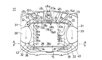
センターパネル61は前パネル62及び背面パネル63を組み合わせて構成されている。背面パネル63は導電性樹脂のポリカーボネートベースの複合樹脂により構成されている。図9及び図10に示すように、前パネル62は上方横方向に延出された横フレーム65を備え、該横フレーム65の左右端から下方に向かってそれぞれ下垂フレーム66が延出形成されている。左右の下垂フレーム66には装飾用LED67(図12参照)を挿入する第1収納ボックス68が形成されている。横フレーム65前面には第2収納ボックス70が装着されている。図10に示すように、第2収納ボックス70正面にはその中央に略正方形の第1窓70aが形成され、該第1窓70aの左右にそれぞれ2つずつ第2窓70bが形成され、該第2窓70bのさらに外側にはそれぞれ2つずつ第3窓70cが形成されている。上記第1の実施の形態と同様に第1窓70aにはLEDよりなる7セグ表示部49が露出されている。第2窓70bからは第1保留ランプ16a〜16dが露出されている。第3窓70cからは第2保留ランプ15a〜15dが露出されている。7セグ表示部49、第1保留ランプ16a〜16d及び第2保留ランプ15a〜15dの機能は上記第1の実施の形態と同様である。第2収納ボックス70の上端には球受け部としての凹部69が形成されている。前パネル62にはほぼ全周に渡ってフランジ71が形成されており、センターパネル61は遊技面12に対してこのフランジ71部分において取り付けられている。従って、センターパネル61のうちこのフランジ71部分よりも後方部分は遊技面12内部に埋設される。
【0066】
下垂フレーム66の両下端間はテーブルフレーム72にて一体的に連結されている。テーブルフレーム72には図9及び図10に示すように左右に一段高い棚73が形成され、両棚73より一段低い中央位置には転動遊技領域を構成する第1広場74が形成されている。第1広場74は中央ほど低くなるように傾斜が形成されている。また、中央には停滞した遊技球を下方に落下させるための傾斜面76が形成されている。第1広場74の後方には防護壁75が形成されている。防護壁75には球受け台77が前方に向かって突出形成されている。球受け台77の上面には遊技球が転動できる転動遊技領域を構成する円形の第2広場78が形成され、その中央には第1広場74に遊技球が落下できるように通過孔79が形成されている。
【0067】
前記横フレーム65と球受け台77との間には二本の案内レール80が配設されている。両案内レール80は第2広場78を挟む左右であって、ちょうど図柄表示部15の三分割された図柄の隣接位置(つまり各図柄を目視するのに邪魔とならない位置)の前方に配置されている。各案内レール80はさらに二本の細フレーム80aにより構成され、両細フレーム80aは所定間隔で左右方向に並んで配置される。両細フレーム80aは、本実施の形態における一誘導部材又は線状体を構成する。両細フレーム80aは補強フレーム81にて上下に二カ所で連結されている。
【0068】
図11に示すように、前パネル62の裏面には前記凹部69に連結されて遊技球を後方に案内する案内通路82が形成されている。案内通路82の下方には弾み板83が装着されている。落下する遊技球は弾み板83上で弾みさらに左右に振り分けられる。
【0069】
図12及び図13に示すように、背面パネル63には3つの同形状の露出孔85が形成されている。露出孔85は前記図柄表示部15の三分割された図柄に対応し、各図柄は露出孔85から目視される。隣接する露出孔85同士は間仕切り壁86にて間仕切られている。間仕切り壁86は本実施の形態における一誘導部材又は所定壁面を有する板体を構成する。二本の間仕切り壁86は前記案内レール80のちょうど後方に配設されている。図15に示すように、間仕切り壁86には、その前面側が前面凹状に形成されることにより、長手方向に沿った誘導溝が形成されている。また、図14に示すように、間仕切り壁86の上下方向には二カ所に凹部86aが形成されている。間仕切り壁86と案内レール80とによって包囲された上下空間が遊技球の流下する流下経路88とされる。つまり、間仕切り壁86と案内レール80(二本の細フレーム80a)によって本実施の形態における誘導手段が構成されている。流下経路88底部にあたる球受け台77には傾斜面90が形成されており、落下して傾斜面90に当接した遊技球を内方、すなわち第2広場78方向に導く。背面パネル63の上方には案内通路82に連結され前記弾み板83上に遊技球を落下させる落下穴89が形成されている。露出孔85の左右には前記装飾用LED67が固着されている。
【0070】
次にこのように構成したパチンコ機の作用について説明する。図示しないハンドルを操作して遊技者は遊技球を遊技面12上に打ち出す。遊技球は釘に弾かれあるいは導かれて一部センターパネル61の凹部69から後方の案内通路82に導入される。導入された遊技球は落下穴89から前記弾み板83上に落ち、ここで弾みながらさらに左右に振り分けられて流下経路88を下降する。遊技球は傾斜面90に当接し球受け台77の第2広場78に至る。流下経路88に至ってからは遊技者は両細フレーム80a間の隙間を介して正面から遊技球を視認可能となる。また、斜め方向からは間仕切り壁86と案内レール80の隙間を介して遊技球を視認可能となる。第2広場78に至った遊技球はその落下した勢いでしばらく第2広場78内で転動した後、通過孔79から第1広場74上に落下する。最終的には傾きにしたがって傾斜面76に導かれ、ここから落下して再び遊技面12に戻される。また、背面パネル63と遊技球が接している限りにおいて、遊技球の転動によって生じた静電気は背面パネル63を通じて遊技盤11側にアースされる。
【0071】
以上詳述したように、流下経路88がパチンコ機の前面側等に開放されている、そこを流下する遊技球の動きが遊技者に目視され、結果として、興趣の向上が図られる。また、開放部分より、球詰まりの解消作業、流下経路88の清掃等を比較的容易に行うことができる。また、中空状の通路を形成しなくともよく誘導手段の構成が簡素化される。さらに、遊技者の視認しやすい部分が所定の透明部材によって構成され筒状となった誘導手段を備えた遊技機に比べ、本実施の形態における遊技機では、所定の透明部材等を別途組み付けなくともよい。結果として、部材点数の削減、遊技機(誘導手段)の構成又は組付け工程の簡素化等を図るとともに、さらなる視認性の向上を図ることができる。また、流下経路88に沿って配設される一誘導部材として、パチンコ機の前面側において配設されているガラス板等を利用していないため、当該ガラス板等が破損してしまうなどの不具合の発生を防止することができる。
【0072】
尚、上述した実施の形態の記載内容に限定されず、例えば次のように実施してもよい。
【0073】
(a)第1の実施の形態において、固定プレート39を設けず、通路43が全域又はほぼ全域において開放された構成としてもよい。また、第2の実施の形態において、両細フレーム80a間に補強フレーム81を設けず、両細フレーム80aが離間した構成とし、案内レール80の全域又はほぼ全域が開放された構成としてもよい。こうすることにより、より長い区間、遊技球の動きが遊技者に視認可能となり、さらなる興趣の向上につながる。
【0074】
(b)上記各実施の形態において、通路43,流下経路88の開放部分(離間部分)が正面を向くものに限らず、開放部分(離間部分)が遊技面12の正面からその略中央部にかけての所定範囲に向けて形成された通路(流下経路)や、開放部分(離間部分)の少なくとも一部が遊技面12の正面から見て視認可能となるように構成された通路(流下経路)等を採用してもよい。例えば、第1の実施の形態において、通路43の開放部分が遊技面12の正面からその略中央部方向に傾いた方向に向くように構成されていてもよい。このようにすれば、開放部分が、遊技者がより遊技球を視認しやすい方向に向くこととなり、遊技球の視認性がより高まる。
【0075】
(c)誘導手段の構成は上記実施の形態に限られるものではない。例えば、並設された3つの線状体によって遊技球の動きを規制し誘導するもの、並設された2つの板体と1つの線状体によって遊技球の動きを規制し誘導するもの、並設された誘導部材としての3つの板体と規制部としての1つの線状体によって遊技球の動きを規制し誘導するもの、並設された2つの板体によって遊技球の動きを規制し誘導するもの等を採用してもよい。なお、上記各誘導手段における遊技球の流下経路が、略直線状のものに限らず、湾曲したり蛇行したりした構成としてもよい。ここで、2つの板体によって構成される誘導手段について詳述すると、当該誘導手段は、相対向した一対の板体が配設され、前記両板体の対向間隔が遊技球の径より狭くなるように構成されるとともに、前記両板体の対向面に一対の誘導溝が形成され、前記両誘導溝の底部同士の間隔が遊技球の径以上の広さとなるように構成されることにより、前記誘導溝に沿って遊技球を誘導する。なお、上記誘導溝が、略直線状のものに限らず、湾曲したり蛇行したりした構成としてもよい。
【0076】
(d)上記実施の形態では、センターパネル17,61に誘導手段としての通路43,流下経路88が設けられている。これに限らず、誘導手段が遊技面12の他の部分に設けられる構成としてもよい。また、通路43,流下経路88が設けられる位置は上記実施の形態における位置に限らず、センターパネル17,61のどこでもよい。
【0077】
(e)上記実施の形態とは異なるタイプのパチンコ機として実施してもよい。また、パチンコ機以外にも雀球、アレンジボール等の遊技機として実施してもよい。
【0078】
(f)通路43,流下経路88の一側部(例えば奥側部分等)において、当該通路43,流下経路88に沿って発光手段(例えば、多数のLED等)を配設して、遊技者が通路43,流下経路88の開放部分(離間部分)から発光手段の発光を視認できるように構成してもよい。このようにすれば、遊技者と発光手段との間に介在するものがより少ないため、発光手段による発光演出がより迫力のあるものとなる。また、遊技者に対して、発光手段の手前側を遊技球Bが通過していくため、発光演出と遊技球Bの動きによる演出がさらなる相乗効果を生みだす。結果として、さらなる興趣の向上を図ることができる。
【発明の効果】
本発明によれば、遊技球の動きを見やすくし、興趣の飛躍的な向上を図ることができる。
【図面の簡単な説明】
【図1】一実施の形態におけるパチンコ機を示す部分正面図である。
【図2】第1の実施の形態におけるセンターパネルを示す斜視図である。
【図3】第1の実施の形態における背面パネルを示す背面斜視図である。
【図4】第1の実施の形態におけるセンターパネルを示す正面図である。
【図5】第1の実施の形態における背面パネルを示す背面図である。
【図6】第1の実施の形態におけるフードパネルを装着した前パネルを示す背面図である。
【図7】図4におけるA−A線断面図。
【図8】第1の実施の形態におけるフードパネルを示す斜視図である。
【図9】第2の実施の形態におけるセンターパネルを示す斜視図である。
【図10】第2の実施の形態におけるセンターパネルを示す正面図である。
【図11】第2の実施の形態における前パネルを示す背面図である。
【図12】第2の実施の形態における背面パネルを示す斜視図である。
【図13】第2の実施の形態におけるセンターパネルを示す背面図である。
【図14】図10におけるB−B線断面図。
【図15】図14におけるC−C線断面図。
【符号の説明】
11…遊技盤、12…遊技領域を有する遊技面、13…図柄表示装置、17,61…特定遊技部材としてのセンターパネル、18…入賞手段としての作動口、32…誘導部材又は板体を構成する湾曲部、34…誘導部材又は板体を構成する段違い部、35…第1転動面、35a…規制部としての小レール、38…第2転動面、38a…規制部としての小レール、41…誘導部材又は板体を構成する面取り部、42…誘導部材又は板体を構成する突出部、43…誘導手段又は誘導流路としての通路、45…誘導部材を構成する基板、50…転動遊技領域としての広場、74…転動遊技領域を構成する第1広場、78…転動遊技領域を構成する第2広場、80…案内レール、80a…誘導部材又は線状体を構成する細フレーム、86…誘導部材又は板体を構成する間仕切り壁、88…流下経路。[0001]
BACKGROUND OF THE INVENTION
The present invention relates to a gaming machine such as a pachinko machine.
[0002]
[Prior art]
Conventionally, as a kind of gaming machine, a pachinko machine having a game board equipped with a symbol display device or the like is known. In such a pachinko machine, a winning device is provided below the symbol display device, and various gaming states, for example, a big hit state advantageous to the player, etc. are derived based on the winning of the game ball to the winning device. Is done.
[0003]
A center panel is provided around the symbol display device, and a stage on which the game ball can roll is provided on the center panel. The game ball guided to the stage rolls on the stage for a while and then wins a prize means depending on how the game ball rolls. For this reason, the player pays attention to the behavior of the game ball on the stage with a sense of expectation.
[0004]
[Problems to be solved by the invention]
Some center panels are provided with a mechanism called a so-called warp channel that guides game balls to the stage. In many cases, the warp channel is formed in a cylindrical shape from the inlet to the outlet in the center panel or the like in order to increase the inductivity of the game ball.
[0005]
For this reason, it is difficult for the player to visually recognize the game ball passing through the warp flow path, which may cause the player to feel uneasy, and the interest of the player who enjoys the behavior of the game ball is reduced. There was a fear.
[0006]
The present invention has been made in view of the above-described problems, and an object of the present invention is to provide a gaming machine that makes it easy to see the movement of a game ball and can dramatically improve the interest.
[0007]
[Means for Solving the Problems]
Means effective for achieving the above object will be described below. In addition, the operation | movement etc. are demonstrated as needed.
BookThe gaming machine according to the invention is
In the game area where the game ball can flow down, it has a specific game member surrounding the variable display device capable of variably displaying the identification information,
A winning means is provided below the specific gaming member,
A gaming machine in which the identification information is variably displayed on the variable display device based on the winning of a game ball to the winning means, and a special game value is given when a predetermined condition is satisfied. ,
The specific gaming member is
It has a rolling game area that allows the rolling of game balls at the lower frame part,
In the rolling game area, provided with an inclined surface for dropping the game ball downward with the winning means,
A flow path of the game ball is formed by a partition part that partitions the display part of the variable display device and a guide rail that is provided in front of the partition part,
The gist is that the game balls introduced from the game area via the upper frame part can be guided to the rolling game area while flowing down from the left and right frame parts at positions separated in the left-right direction..
[0008]
DETAILED DESCRIPTION OF THE INVENTION
The guide means is a guide flow path arranged so that at least one guide member surrounds a flow path through which the game ball flows down,
A gaming machine, wherein at least one section of the flow-down path is open.
[0009]
According to the
[0010]
Mean 2. In a game area where a game ball can flow down, it is provided with guidance means for guiding the game ball while flowing down,
The guide means is constituted by a plurality of guide members arranged around the flow path through which the game ball flows down and along the flow path,
A gaming machine, wherein at least one section of the flow-down path is open.
[0011]
According to the
[0012]
Means 3. In the
[0013]
According to the means 3, the longer section and the movement of the game ball can be visually recognized by the player, which leads to further enhancement of interest.
[0014]
[0015]
According to the
[0016]
Means 5. In any one of the
[0017]
According to the means 5, since the opening width is narrower than the diameter of the game ball, it is possible to prevent a problem that the game ball jumps out from the open portion.
[0018]
Means 6. A gaming machine according to any one of
[0019]
According to the means 6, it is possible to prevent a problem that the game ball jumps out from the open portion, and to further increase the inductivity of the game ball. It should be noted that “the restriction portion may be provided apart from the guide means” or “the restriction portion may be provided integrally with the guide member”. By providing integrally with the guide member, the number of parts can be reduced. Moreover, it is good also as "the said control part is provided along the said flow-down path | route in at least one area of the said flow-down path | route." Thereby, it is possible to more reliably prevent the game ball from jumping out from the open portion, and the inductivity is further increased.
[0020]
Mean 7 In a game area where a game ball can flow down, it is provided with guidance means for guiding the game ball while flowing down,
The guide means includes a plurality of guide members arranged around the flow path of the game ball and along the flow path,
A gaming machine, wherein at least one of the plurality of guide members is configured to be separated from the other guide members.
[0021]
According to the means 7, since at least one of the plurality of guide members is separated from the other guide members, a gap is generated in the guide means in the whole area or almost the whole area of the flow path of the game ball. Therefore, by directing this gap (spaced portion) toward the player, the movement of the guided game ball can be visually recognized by the player, and as a result, the interest is improved. In addition, it is possible to relatively easily perform the clogging work, the cleaning of the guiding means, and the like from the separated portion. In addition, there is a gaming machine provided with a guiding means in which a portion that is easily visible to the player is formed of a predetermined transparent member and is cylindrical. Compared to such a gaming machine, the gaming machine having the above-described means 7 has a gaming machine. Since the predetermined transparent member or the like is not separately assembled, the number of members can be reduced, the configuration of the gaming machine or the assembling process can be simplified, and the visibility can be further improved. It is also conceivable to use a glass plate or the like disposed on the front side of a gaming machine such as a pachinko machine as one of the guiding members. However, in this case, the glass plate or the like may be damaged or damaged. Therefore, there is a risk that visibility may be lowered, and it is more preferable not to use a glass plate or the like as the guide member. The flow-down path indicates a path along which the game ball flows down.
[0022]
Means 8. The gaming machine according to claim 7, wherein the spaced-apart portion is configured to face a substantially central portion of the gaming area from the front of the gaming area.
[0023]
According to the means 8, the separated portion is directed in a direction in which the player can more easily see the game ball, and the visibility of the game ball is further increased. Similarly, “at least a part of the separated portion may be configured to be visible when viewed from the front of the gaming area”.
[0024]
Means 9. The gaming machine according to claim 7 or 8, wherein a spacing distance in a direction substantially orthogonal to the flow-down direction of the game ball is narrower than a diameter of the game ball.
[0025]
According to the means 9, since the separation interval is narrower than the diameter of the game ball, it is possible to prevent a problem that the game ball jumps out from the separation portion.
[0026]
Means 10. In any one of the means 7 to 9, a gaming machine characterized in that a regulation part for regulating the jumping-out of the game ball from the separated portion is provided in at least one section of the flow-down path.
[0027]
According to the means 10, it is possible to prevent a problem that the game ball jumps out from the separated portion, and to further increase the inductivity of the game ball. In addition, it is good also as "the said control part being integrally provided in the said guide member." By providing integrally with the guide member, the number of parts can be reduced. Moreover, it is good also as "the said control part is provided along the said flow-down path | route in at least one area of the said flow-down path | route." Thereby, it is possible to more reliably prevent the game ball from jumping out from the separated portion, and the inductivity is further increased.
[0028]
[0029]
According to the
[0030]
[0031]
According to the
[0032]
[0033]
According to the
[0034]
Means 14. In a game area where a game ball can flow down, it is provided with guidance means for guiding the game ball while flowing down,
The guide means is constituted by a pair of plates facing each other across the flow path of the game ball,
The opposing distance between the two plates is configured to be narrower than the diameter of the game ball,
A pair of guide grooves along the flow path is formed on the opposing surfaces of the two plate bodies,
A gaming machine, characterized in that an interval between the bottoms of both guiding grooves is configured to be larger than the diameter of the gaming ball.
[0035]
According to the means 14, the game ball can be guided along the guide grooves formed in the pair of opposed plates, so that the guide means can be opened along the flow path. Therefore, by directing this open portion to the player side, the movement of the guided game ball can be visually recognized by the player, and as a result, the interest is improved. In addition, it is possible to relatively easily carry out the work of eliminating the clogging of the balls and the cleaning of the guiding means from the open part. In addition, there is a gaming machine provided with guiding means in which a portion that is easy for a player to visually recognize is formed of a predetermined transparent member and is cylindrical. Compared to such a gaming machine, in the gaming machine having the above-described means 14, Since the predetermined transparent member or the like is not separately assembled, the number of members can be reduced, the configuration of the gaming machine or the assembling process can be simplified, and the visibility can be further improved. It is also conceivable to use a glass plate or the like disposed on the front side of a gaming machine such as a pachinko machine as one of the guiding members. However, in this case, the glass plate or the like may be damaged or damaged. Therefore, there is a risk that visibility may be lowered, and it is more preferable not to use a glass plate or the like as the guide member. The flow path is a path through which the game ball flows, and is different from a specific flow path. In addition, at least one of the plate body and the guide groove includes a substantially straight shape, a curved shape, a meandering shape, and the like.
[0036]
The guide means includes a plate disposed along the flow path of the game ball,
A plurality of linear bodies arranged along the plate body,
A gaming machine, wherein the plate body and the plurality of linear bodies are separated from each other, and the separation interval is configured to be narrower than a diameter of the game ball.
[0037]
According to the
[0038]
The gaming machine, wherein the guiding means is provided integrally with the specific gaming member and configured to guide the gaming ball flowing down the gaming area to the rolling gaming area.
[0039]
[0040]
A gaming machine configured to allow a player to visually recognize light emitted from the light emitting means through the guiding members.
[0041]
According to the
[0042]
[0043]
[First Embodiment]
Hereinafter, a first embodiment of a pachinko gaming machine (hereinafter simply referred to as a “pachinko machine”) will be described in detail with reference to the drawings.
[0044]
As shown in FIG. 1, the pachinko machine includes a
[0045]
Below the
[0046]
A pair of passing
[0047]
On the
[0048]
In the present embodiment, the inner rail and the outer rail are concealed in the
[0049]
Next, the
[0050]
As shown in FIGS. 1, 2, and 4, a
[0051]
As shown in FIGS. 1, 2, 4, 7 and 8, a
[0052]
The distance between the first rolling
[0053]
As shown in FIG. 2, since the front surface of the bent portion 44 is covered with the fixed
[0054]
As shown in FIGS. 3 and 5, the
[0055]
A square 50 as a rolling game area is formed below the
[0056]
A
[0057]
As shown in FIG. 4, a substantially square first through
[0058]
The first
[0059]
Here, when the game ball passes through the passing
[0060]
In addition, as described above, the
[0061]
As shown in FIG. 7, the
[0062]
Next, the operation of the pachinko machine configured as described above will be described. By operating a handle (not shown), the player launches a game ball onto the
[0063]
As described above in detail, since the
[0064]
[Second Embodiment]
Next, a pachinko machine according to a second embodiment will be described with reference to FIGS. Also in the second embodiment, the outline of the pachinko machine is the same as that of the first embodiment, so only the
[0065]
The
[0066]
A
[0067]
Two
[0068]
As shown in FIG. 11, a
[0069]
As shown in FIGS. 12 and 13, the
[0070]
Next, the operation of the pachinko machine configured as described above will be described. By operating a handle (not shown), the player launches a game ball onto the
[0071]
As described above in detail, the
[0072]
In addition, it is not limited to the description content of embodiment mentioned above, For example, you may implement as follows.
[0073]
(A) In the first embodiment, the fixed
[0074]
(B) In each of the above-described embodiments, the open portion (separated portion) of the
[0075]
(C) The configuration of the guiding means is not limited to the above embodiment. For example, one that regulates and guides the movement of a game ball by three linear bodies arranged side by side, one that regulates and guides the movement of a game ball by two parallel plates and one linear body, The movement of the game ball is regulated and guided by the three plates as the guiding members and the linear body as the regulating portion, and the movement of the game ball is regulated and guided by the two plates arranged in parallel. You may adopt what to do. Note that the flow path of the game ball in each of the guiding means is not limited to a substantially straight one, and may be configured to be curved or meandering. Here, the guiding means constituted by two plate bodies will be described in detail. The guiding means is provided with a pair of opposed plate bodies, and the facing distance between the two plate bodies is narrower than the diameter of the game ball. And a pair of guide grooves are formed on the opposing surfaces of the two plate bodies, and the distance between the bottoms of the both guide grooves is larger than the diameter of the game ball. A game ball is guided along the guide groove. Note that the guide groove is not limited to a substantially linear shape, and may be curved or meandering.
[0076]
(D) In the above embodiment, the
[0077]
(E) It may be implemented as a pachinko machine of a different type from the above embodiment.Moreover, you may implement as game machines, such as a sparrow ball and an arrangement ball, besides a pachinko machine.
[0078]
(F) On one side of the
【The invention's effect】
According to the present invention, it is possible to make the movement of the game ball easy to see and to dramatically improve the interest.
[Brief description of the drawings]
FIG. 1 is a partial front view showing a pachinko machine according to an embodiment.
FIG. 2 is a perspective view showing a center panel according to the first embodiment.
FIG. 3 is a rear perspective view showing the rear panel in the first embodiment.
FIG. 4 is a front view showing a center panel in the first embodiment.
FIG. 5 is a rear view showing the rear panel in the first embodiment.
FIG. 6 is a rear view showing the front panel on which the hood panel is mounted in the first embodiment.
7 is a cross-sectional view taken along line AA in FIG.
FIG. 8 is a perspective view showing a hood panel in the first embodiment.
FIG. 9 is a perspective view showing a center panel in the second embodiment.
FIG. 10 is a front view showing a center panel in the second embodiment.
FIG. 11 is a rear view showing a front panel according to the second embodiment.
FIG. 12 is a perspective view showing a back panel according to the second embodiment.
FIG. 13 is a rear view showing a center panel in the second embodiment.
14 is a sectional view taken along line BB in FIG.
15 is a sectional view taken along line CC in FIG.
[Explanation of symbols]
DESCRIPTION OF
Claims (2)
前記特定遊技部材の下方に入賞手段を備え、
前記入賞手段に遊技球が入賞することに基づいて、前記可変表示装置にて前記識別情報が変動表示されるとともに、所定条件が成立した場合には特別遊技価値が付与される遊技機であって、
前記特定遊技部材は、
その下辺のフレーム部にて遊技球の転動を許容する転動遊技領域を備え、
前記転動遊技領域にて、遊技球を前記入賞手段のある下方へ落下させる傾斜面を備え、
前記可変表示装置の表示部を仕切る間仕切り部と、当該間仕切り部の前方に離間して設けられた案内レールとによって、遊技球の流下経路を形成し、
上辺のフレーム部を介して前記遊技領域から導入される遊技球を、左右のフレーム部から左右方向に離間した位置にて流下させつつ前記転動遊技領域へ誘導可能としたことを特徴とする遊技機。In the game area where the game ball can flow down, it has a specific game member surrounding the variable display device capable of variably displaying the identification information,
A winning means is provided below the specific gaming member,
A gaming machine in which the identification information is variably displayed on the variable display device based on the winning of a game ball to the winning means, and a special game value is given when a predetermined condition is satisfied. ,
The specific gaming member is
It has a rolling game area that allows the rolling of game balls at the lower frame part,
In the rolling game area, provided with an inclined surface for dropping the game ball downward with the winning means,
A flow path of the game ball is formed by a partition part that partitions the display part of the variable display device and a guide rail that is provided in front of the partition part,
A game characterized in that a game ball introduced from the game area via the upper frame part can be guided to the rolling game area while flowing down at a position separated from the left and right frame parts in the left-right direction. Machine.
Priority Applications (1)
| Application Number | Priority Date | Filing Date | Title |
|---|---|---|---|
| JP2002021661A JP4470356B2 (en) | 2002-01-30 | 2002-01-30 | Game machine |
Applications Claiming Priority (1)
| Application Number | Priority Date | Filing Date | Title |
|---|---|---|---|
| JP2002021661A JP4470356B2 (en) | 2002-01-30 | 2002-01-30 | Game machine |
Related Child Applications (1)
| Application Number | Title | Priority Date | Filing Date |
|---|---|---|---|
| JP2009163413A Division JP4935863B2 (en) | 2009-07-10 | 2009-07-10 | Game machine |
Publications (3)
| Publication Number | Publication Date |
|---|---|
| JP2003220201A JP2003220201A (en) | 2003-08-05 |
| JP2003220201A5 JP2003220201A5 (en) | 2005-08-11 |
| JP4470356B2 true JP4470356B2 (en) | 2010-06-02 |
Family
ID=27744832
Family Applications (1)
| Application Number | Title | Priority Date | Filing Date |
|---|---|---|---|
| JP2002021661A Expired - Fee Related JP4470356B2 (en) | 2002-01-30 | 2002-01-30 | Game machine |
Country Status (1)
| Country | Link |
|---|---|
| JP (1) | JP4470356B2 (en) |
Families Citing this family (3)
| Publication number | Priority date | Publication date | Assignee | Title |
|---|---|---|---|---|
| JP2006304911A (en) * | 2005-04-27 | 2006-11-09 | Heiwa Corp | Pachinko game machine |
| JP4868860B2 (en) * | 2006-01-25 | 2012-02-01 | 株式会社ソフイア | Game machine |
| JP5568279B2 (en) * | 2009-11-02 | 2014-08-06 | 株式会社ニューギン | Game machine |
-
2002
- 2002-01-30 JP JP2002021661A patent/JP4470356B2/en not_active Expired - Fee Related
Also Published As
| Publication number | Publication date |
|---|---|
| JP2003220201A (en) | 2003-08-05 |
Similar Documents
| Publication | Publication Date | Title |
|---|---|---|
| JP5493489B2 (en) | Game machine | |
| JP2008017861A (en) | Pachinko machine | |
| JP2006230486A (en) | Game board of pachinko game machine | |
| JP4470356B2 (en) | Game machine | |
| JP4935863B2 (en) | Game machine | |
| JP5493487B2 (en) | Game machine | |
| JP5261652B2 (en) | Game machine | |
| JP6512260B2 (en) | Gaming machine | |
| JP5493488B2 (en) | Game machine | |
| JP6237807B2 (en) | Game machine | |
| JP6217732B2 (en) | Game machine | |
| JP6870698B2 (en) | Game machine | |
| JP5747222B2 (en) | Game machine | |
| JP5549123B2 (en) | Game machine | |
| JP4703532B2 (en) | Game machine | |
| JP6540768B2 (en) | Gaming machine | |
| JP4896649B2 (en) | Bullet ball machine | |
| JP2024021567A (en) | Game machine | |
| JP6116431B2 (en) | Game machine | |
| JP4823839B2 (en) | Bullet ball machine | |
| JP2002052193A (en) | Game machine | |
| JP5386724B2 (en) | Game machine | |
| JP2015029731A (en) | Game machine | |
| JP2019147032A (en) | Game machine | |
| JP5386725B2 (en) | Game machine |
Legal Events
| Date | Code | Title | Description |
|---|---|---|---|
| A521 | Written amendment |
Free format text: JAPANESE INTERMEDIATE CODE: A523 Effective date: 20050125 |
|
| A621 | Written request for application examination |
Free format text: JAPANESE INTERMEDIATE CODE: A621 Effective date: 20050125 |
|
| A977 | Report on retrieval |
Free format text: JAPANESE INTERMEDIATE CODE: A971007 Effective date: 20080716 |
|
| A131 | Notification of reasons for refusal |
Free format text: JAPANESE INTERMEDIATE CODE: A131 Effective date: 20080805 |
|
| A521 | Written amendment |
Free format text: JAPANESE INTERMEDIATE CODE: A523 Effective date: 20080929 |
|
| A131 | Notification of reasons for refusal |
Free format text: JAPANESE INTERMEDIATE CODE: A131 Effective date: 20090512 |
|
| A521 | Written amendment |
Free format text: JAPANESE INTERMEDIATE CODE: A523 Effective date: 20090710 |
|
| TRDD | Decision of grant or rejection written | ||
| A01 | Written decision to grant a patent or to grant a registration (utility model) |
Free format text: JAPANESE INTERMEDIATE CODE: A01 Effective date: 20100209 |
|
| A01 | Written decision to grant a patent or to grant a registration (utility model) |
Free format text: JAPANESE INTERMEDIATE CODE: A01 |
|
| A61 | First payment of annual fees (during grant procedure) |
Free format text: JAPANESE INTERMEDIATE CODE: A61 Effective date: 20100222 |
|
| FPAY | Renewal fee payment (event date is renewal date of database) |
Free format text: PAYMENT UNTIL: 20130312 Year of fee payment: 3 |
|
| R150 | Certificate of patent or registration of utility model |
Ref document number: 4470356 Country of ref document: JP Free format text: JAPANESE INTERMEDIATE CODE: R150 Free format text: JAPANESE INTERMEDIATE CODE: R150 |
|
| FPAY | Renewal fee payment (event date is renewal date of database) |
Free format text: PAYMENT UNTIL: 20130312 Year of fee payment: 3 |
|
| FPAY | Renewal fee payment (event date is renewal date of database) |
Free format text: PAYMENT UNTIL: 20160312 Year of fee payment: 6 |
|
| R250 | Receipt of annual fees |
Free format text: JAPANESE INTERMEDIATE CODE: R250 |
|
| R250 | Receipt of annual fees |
Free format text: JAPANESE INTERMEDIATE CODE: R250 |
|
| R250 | Receipt of annual fees |
Free format text: JAPANESE INTERMEDIATE CODE: R250 |
|
| R250 | Receipt of annual fees |
Free format text: JAPANESE INTERMEDIATE CODE: R250 |
|
| R250 | Receipt of annual fees |
Free format text: JAPANESE INTERMEDIATE CODE: R250 |
|
| R250 | Receipt of annual fees |
Free format text: JAPANESE INTERMEDIATE CODE: R250 |
|
| LAPS | Cancellation because of no payment of annual fees |