JP4469722B2 - Beam - Google Patents
Beam Download PDFInfo
- Publication number
- JP4469722B2 JP4469722B2 JP2004545602A JP2004545602A JP4469722B2 JP 4469722 B2 JP4469722 B2 JP 4469722B2 JP 2004545602 A JP2004545602 A JP 2004545602A JP 2004545602 A JP2004545602 A JP 2004545602A JP 4469722 B2 JP4469722 B2 JP 4469722B2
- Authority
- JP
- Japan
- Prior art keywords
- metal member
- cross
- roll forming
- during
- end view
- Prior art date
- Legal status (The legal status is an assumption and is not a legal conclusion. Google has not performed a legal analysis and makes no representation as to the accuracy of the status listed.)
- Expired - Lifetime
Links
Images


Classifications
-
- E—FIXED CONSTRUCTIONS
- E04—BUILDING
- E04B—GENERAL BUILDING CONSTRUCTIONS; WALLS, e.g. PARTITIONS; ROOFS; FLOORS; CEILINGS; INSULATION OR OTHER PROTECTION OF BUILDINGS
- E04B1/00—Constructions in general; Structures which are not restricted either to walls, e.g. partitions, or floors or ceilings or roofs
- E04B1/18—Structures comprising elongated load-supporting parts, e.g. columns, girders, skeletons
- E04B1/24—Structures comprising elongated load-supporting parts, e.g. columns, girders, skeletons the supporting parts consisting of metal
-
- E—FIXED CONSTRUCTIONS
- E04—BUILDING
- E04C—STRUCTURAL ELEMENTS; BUILDING MATERIALS
- E04C3/00—Structural elongated elements designed for load-supporting
- E04C3/02—Joists; Girders, trusses, or trusslike structures, e.g. prefabricated; Lintels; Transoms; Braces
- E04C3/04—Joists; Girders, trusses, or trusslike structures, e.g. prefabricated; Lintels; Transoms; Braces of metal
- E04C3/06—Joists; Girders, trusses, or trusslike structures, e.g. prefabricated; Lintels; Transoms; Braces of metal with substantially solid, i.e. unapertured, web
- E04C3/07—Joists; Girders, trusses, or trusslike structures, e.g. prefabricated; Lintels; Transoms; Braces of metal with substantially solid, i.e. unapertured, web at least partly of bent or otherwise deformed strip- or sheet-like material
-
- B—PERFORMING OPERATIONS; TRANSPORTING
- B21—MECHANICAL METAL-WORKING WITHOUT ESSENTIALLY REMOVING MATERIAL; PUNCHING METAL
- B21B—ROLLING OF METAL
- B21B1/00—Metal-rolling methods or mills for making semi-finished products of solid or profiled cross-section; Sequence of operations in milling trains; Layout of rolling-mill plant, e.g. grouping of stands; Succession of passes or of sectional pass alternations
- B21B1/08—Metal-rolling methods or mills for making semi-finished products of solid or profiled cross-section; Sequence of operations in milling trains; Layout of rolling-mill plant, e.g. grouping of stands; Succession of passes or of sectional pass alternations for rolling structural sections, i.e. work of special cross-section, e.g. angle steel
-
- B—PERFORMING OPERATIONS; TRANSPORTING
- B21—MECHANICAL METAL-WORKING WITHOUT ESSENTIALLY REMOVING MATERIAL; PUNCHING METAL
- B21D—WORKING OR PROCESSING OF SHEET METAL OR METAL TUBES, RODS OR PROFILES WITHOUT ESSENTIALLY REMOVING MATERIAL; PUNCHING METAL
- B21D47/00—Making rigid structural elements or units, e.g. honeycomb structures
- B21D47/01—Making rigid structural elements or units, e.g. honeycomb structures beams or pillars
-
- B—PERFORMING OPERATIONS; TRANSPORTING
- B21—MECHANICAL METAL-WORKING WITHOUT ESSENTIALLY REMOVING MATERIAL; PUNCHING METAL
- B21D—WORKING OR PROCESSING OF SHEET METAL OR METAL TUBES, RODS OR PROFILES WITHOUT ESSENTIALLY REMOVING MATERIAL; PUNCHING METAL
- B21D5/00—Bending sheet metal along straight lines, e.g. to form simple curves
- B21D5/06—Bending sheet metal along straight lines, e.g. to form simple curves by drawing procedure making use of dies or forming-rollers, e.g. making profiles
- B21D5/08—Bending sheet metal along straight lines, e.g. to form simple curves by drawing procedure making use of dies or forming-rollers, e.g. making profiles making use of forming-rollers
- B21D5/086—Bending sheet metal along straight lines, e.g. to form simple curves by drawing procedure making use of dies or forming-rollers, e.g. making profiles making use of forming-rollers for obtaining closed hollow profiles
-
- E—FIXED CONSTRUCTIONS
- E04—BUILDING
- E04C—STRUCTURAL ELEMENTS; BUILDING MATERIALS
- E04C3/00—Structural elongated elements designed for load-supporting
- E04C3/02—Joists; Girders, trusses, or trusslike structures, e.g. prefabricated; Lintels; Transoms; Braces
- E04C3/04—Joists; Girders, trusses, or trusslike structures, e.g. prefabricated; Lintels; Transoms; Braces of metal
- E04C2003/0404—Joists; Girders, trusses, or trusslike structures, e.g. prefabricated; Lintels; Transoms; Braces of metal beams, girders, or joists characterised by cross-sectional aspects
- E04C2003/0408—Joists; Girders, trusses, or trusslike structures, e.g. prefabricated; Lintels; Transoms; Braces of metal beams, girders, or joists characterised by cross-sectional aspects characterised by assembly or the cross-section
- E04C2003/0421—Joists; Girders, trusses, or trusslike structures, e.g. prefabricated; Lintels; Transoms; Braces of metal beams, girders, or joists characterised by cross-sectional aspects characterised by assembly or the cross-section comprising one single unitary part
-
- E—FIXED CONSTRUCTIONS
- E04—BUILDING
- E04C—STRUCTURAL ELEMENTS; BUILDING MATERIALS
- E04C3/00—Structural elongated elements designed for load-supporting
- E04C3/02—Joists; Girders, trusses, or trusslike structures, e.g. prefabricated; Lintels; Transoms; Braces
- E04C3/04—Joists; Girders, trusses, or trusslike structures, e.g. prefabricated; Lintels; Transoms; Braces of metal
- E04C2003/0404—Joists; Girders, trusses, or trusslike structures, e.g. prefabricated; Lintels; Transoms; Braces of metal beams, girders, or joists characterised by cross-sectional aspects
- E04C2003/0426—Joists; Girders, trusses, or trusslike structures, e.g. prefabricated; Lintels; Transoms; Braces of metal beams, girders, or joists characterised by cross-sectional aspects characterised by material distribution in cross section
- E04C2003/043—Joists; Girders, trusses, or trusslike structures, e.g. prefabricated; Lintels; Transoms; Braces of metal beams, girders, or joists characterised by cross-sectional aspects characterised by material distribution in cross section the hollow cross-section comprising at least one enclosed cavity
-
- E—FIXED CONSTRUCTIONS
- E04—BUILDING
- E04C—STRUCTURAL ELEMENTS; BUILDING MATERIALS
- E04C3/00—Structural elongated elements designed for load-supporting
- E04C3/02—Joists; Girders, trusses, or trusslike structures, e.g. prefabricated; Lintels; Transoms; Braces
- E04C3/04—Joists; Girders, trusses, or trusslike structures, e.g. prefabricated; Lintels; Transoms; Braces of metal
- E04C2003/0404—Joists; Girders, trusses, or trusslike structures, e.g. prefabricated; Lintels; Transoms; Braces of metal beams, girders, or joists characterised by cross-sectional aspects
- E04C2003/0443—Joists; Girders, trusses, or trusslike structures, e.g. prefabricated; Lintels; Transoms; Braces of metal beams, girders, or joists characterised by cross-sectional aspects characterised by substantial shape of the cross-section
- E04C2003/0465—Joists; Girders, trusses, or trusslike structures, e.g. prefabricated; Lintels; Transoms; Braces of metal beams, girders, or joists characterised by cross-sectional aspects characterised by substantial shape of the cross-section square- or rectangular-shaped
Description
本発明はロール成形梁および梁のロール成形方法に関する。 The present invention relates to a roll forming beam and a beam roll forming method.
本発明は、住宅および建造物、特に家の増築用に比較的軽量の略矩形断面の梁を製造するために主に考案され、このような用途に関連して以下に説明される。しかしながら、本発明がこのような特定分野の使用に限定されないことを理解されたい。 The present invention is primarily devised to produce relatively light, generally rectangular cross-section beams for homes and buildings, particularly home extensions, and is described below in connection with such applications. However, it should be understood that the present invention is not limited to such specific fields of use.
背景技術
既知の軽量建築梁の一形状は、増築で用いられるように、2つのロール成形されたC形断面チャネル(溝、溝部、溝状部材)を接合して矩形断面の梁を形成することによって製造される。
BACKGROUND ART One known lightweight building beam shape is to join two roll-formed C-shaped cross-section channels (groove, groove, groove-like member) to form a rectangular cross-section beam for use in extension. Manufactured by.
この既知の梁に関する短所は、2つのチャネルが互いに対して滑ることがあり、梁のそり、強度の低下、および/またはきしみ音の発生を引き起こしかねないことである。極端な状況下では、この2つのチャネルがねじれ、および/または互いに分離することもあり、その結果、一般に梁欠陥となる。この既知の梁の別の短所は、製造が2つのC形断面チャネルの形成、プレス機における2つのチャネルの位置決め、および次のチャネルを接合するプレス作業を含む、少なくとも2段階の2人での作業となることである。 The disadvantage with this known beam is that the two channels can slide relative to each other, which can cause beam warpage, reduced strength, and / or squeak. Under extreme circumstances, the two channels may twist and / or separate from each other, resulting in beam defects generally. Another disadvantage of this known beam is that at least two stages of manufacture include the formation of two C-section channels, the positioning of the two channels in a press, and the pressing operation to join the next channel. It becomes work.
発明の目的
本発明の目的は上記従来技術の短所の1つまたは複数を実質的に克服するか、または少なくとも改善することである。
The object of the present invention is to substantially overcome or at least ameliorate one or more of the disadvantages of the prior art described above.
発明の概要
したがって、第1の態様において、本発明は、金属の単一部材から形成される略矩形断面のロール成形梁であって、前記金属部材の少なくとも3つの隣接する層で形成された、対向する第1および第2の略平行な壁部と、第1および第2の壁部の間の対向する第3および第4の略平行な壁部であって、第3または第4の壁部の一方が金属部材の2つの対向する縦方向の縁部を接合する継ぎ目を有する壁部と、を備える梁を提供する。
SUMMARY OF THE INVENTION Accordingly, in a first aspect, the present invention is a roll-formed beam having a generally rectangular cross-section formed from a single piece of metal formed from at least three adjacent layers of the metal piece. Opposing first and second substantially parallel wall portions and opposing third and fourth substantially parallel wall portions between the first and second wall portions, the third or fourth wall And a wall having a seam where one of the sections joins two opposing longitudinal edges of the metal member.
好ましくは、対向する第1および第2の壁部が前記金属部材の3つの隣接する層で形成されている。 Preferably, the opposing first and second wall portions are formed of three adjacent layers of the metal member.
一形態では、3つの層が第1および第2の壁部の全幅にわたっている。別の形態では、 第1および第2の壁部の3つの層が、第1および第2の壁部のおよそ半分の幅にわたる2つの金属層と、第1および第2の壁部の全幅にわたる1つの層とから形成されている。1実施形態では、2つの半幅層が梁の外側を形成する。別の実施形態では、2つの半幅層が梁の内側を形成する。 In one form, three layers span the entire width of the first and second walls. In another form, the three layers of the first and second walls span two metal layers that span approximately half the width of the first and second walls and the entire width of the first and second walls. And one layer. In one embodiment, the two half-width layers form the outside of the beam. In another embodiment, the two half-width layers form the inside of the beam.
梁が、その4つの隅部の第1および第2の壁部から離れる方向に向かう領域に、好ましくは前記金属部材の少なくとも2つの、最も好ましくは3つの隣接する層も含む。 The beam also includes at least two, most preferably three adjacent layers of the metal member, preferably in a region facing away from the first and second walls of its four corners.
梁が、好ましくは、第3および第4の壁部に複数の外側に凹んだくぼみも含む。好ましい形態では、梁が、第3および第4の壁部のそれぞれに3つの等間隔のくぼみを含み、くぼみのうち1つが継ぎ目により形成されている。 The beam preferably also includes a plurality of outwardly recessed depressions in the third and fourth walls. In a preferred form, the beam includes three equally spaced recesses in each of the third and fourth walls, one of the recesses being formed by a seam.
好ましくは、第1および第2の壁部が第3および第4の壁部よりも小さい。 Preferably, the first and second wall portions are smaller than the third and fourth wall portions.
第2の態様において、本発明は、略矩形断面の梁を略平坦な金属の単一部材からロール成形する方法であって、前記金属部材に、前記金属の少なくとも3つの層の一対の離間された平坦化部分を形成し、金属部材の外側縁部を、平坦化部分の最外端に近づくように平坦化部分と約直角に折り曲げ、折り曲げられた金属部材の外側縁部を、平坦化部分の最内端に近づくように平坦化部分と約直角に折り曲げ、金属部材の隣接する最の外側の縦方向の縁部間の接合継ぎ目を折畳む順次ステップを含む方法を提供する。 In a second aspect, the present invention is a method of roll forming a substantially rectangular cross-section beam from a single member of a substantially flat metal, wherein the metal member is spaced apart by a pair of at least three layers of the metal. Forming a flattened portion, bending the outer edge of the metal member approximately at right angles to the flattened portion so as to approach the outermost end of the flattened portion, and the outer edge of the bent metal member to the flattened portion. Providing a method comprising sequential steps of folding at approximately a right angle with the flattened portion so as to approach the innermost edge of the metal member and folding the joint seam between adjacent outermost longitudinal edges of the metal member.
一形態では、平坦化部分が、金属部材にそれぞれ1つの基部と2つの側部を有する離間された一対のチャネルを形成し、チャネル基部を金属部材の残りの部分に対して側部を挟んで平坦化することによって形成される。 In one form, the planarizing portion forms a pair of spaced apart channels each having one base and two sides on the metal member, with the channel base sandwiching the side with respect to the rest of the metal member. It is formed by flattening.
別の形態では、平坦化部分が、金属部材に1つの基部と2つの側部を有するチャネルを形成し、チャネル側部をチャネル基部に対して平坦化することによって形成される。 In another form, the planarization portion is formed by forming a channel having one base and two sides in a metal member and planarizing the channel side with respect to the channel base.
好ましくは、チャネル基部が、各チャネルの側部の縁部を一緒に基部から離すように延伸することによって平坦化される。 Preferably, the channel base is planarized by stretching the side edges of each channel together away from the base.
金属部材の外側縁部が、平坦化されたチャネル基部の長さの約15%に沿って、平坦化されたチャネル基部に好ましくは約直角に折り曲げられる。金属部材の折り曲げられた外側縁部が、好ましくは、平坦化されたチャネル基部の長さの約15%に沿って、平坦化されたチャネル基部に約直角に折り曲げられる。 The outer edge of the metal member is folded to the flattened channel base, preferably about a right angle, along about 15% of the length of the flattened channel base. The folded outer edge of the metal member is preferably folded at approximately right angles to the planarized channel base along about 15% of the length of the planarized channel base.
金属部材の外側縁部が、平坦化されたチャネル基部の長さの約15%に沿って、平坦化されたチャネル基部に好ましくは約直角に折り曲げられる。金属部材の折り曲げられた外側縁部が、好ましくは、平坦化されたチャネル基部の長さの約15%に沿って、平坦化されたチャネル基部に約直角に折り曲げられる。 The outer edge of the metal member is folded to the flattened channel base, preferably about a right angle, along about 15% of the length of the flattened channel base. The folded outer edge of the metal member is preferably folded at approximately right angles to the planarized channel base along about 15% of the length of the planarized channel base.
方法が、金属部材の外側縁部を平坦化されたチャネル基部に対して折り曲げる前に、金属部材内に好ましくは複数の、最も好ましくは5つのくぼみを形成することも含む。好ましい形態では、3つのくぼみが平坦化されたチャネル基部間に折り畳まれ、1つのくぼみが各平坦化されたチャネル基部の外側に向かって金属部材内に折り込まれる。 The method also includes forming preferably a plurality, most preferably five indentations in the metal member before folding the outer edge of the metal member against the planarized channel base. In a preferred form, three indentations are folded between the flattened channel bases, and one indentation is folded into the metal member toward the outside of each flattened channel base.
好ましい実施形態の詳細な説明
まず図1〜39を参照すると、本発明にしたがって、金属42の単一部材からなる略矩形断面のロール成形梁40の第1の実施形態が示されている。
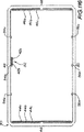
Detailed Description of the Preferred Embodiments Referring first to FIGS. 1-39, a first embodiment of a generally rectangular cross-section roll-formed
図1に最も良く示したように、梁40は、それぞれ前記金属部材42の3つの隣接層44a、44bおよび44c、ならびに46a、46bおよび46cからなる第1および第2の平行壁部44および46を有する。梁40は、使用に際しては一般に、壁部44および46がそれぞれ梁40の上下壁部となるように設置される。また、梁40は、対向する第3および第4の略平行な壁部48および50を有し、使用に際しては梁40の側壁部となる。壁部48は、以下により詳細に説明されるように、金属部材42の最も外側の縦方向の縁部42aおよび42bを接合する折り返し継ぎ目52を有する。
As best shown in FIG. 1, the
梁40の側壁部48は外側に凹んだくぼみ54a、54bおよび54cをその中に有する。くぼみ54bは継ぎ目52の副生成物である。側壁部50は3つの同様のくぼみ56a、56bおよび56cを有する。
3層構造の上下壁部44および46は、2つの側壁部48および50間にわたる内部層44cと、それぞれが2つの側壁部48および50間の約半分の距離にわたっている2つの半層44aおよび44bからなる。上下壁部44および46の3層構造は、梁40に強度を付加する。また、3層構造は上下壁部44および46から梁40の隅部を曲がって側壁部48および50の方向へ伸びている。これによって、それぞれ側壁部48および50の全長の約15%である領域58において、側壁部48および50が補強される。
The upper and
梁40は、BHP Steel Limited.により製造されるように、110mm(すなわち壁部48および50)の高さ、60mm(すなわち壁部44および46)の幅を有し、0.55mm厚のCOLORBOND(登録商標)材料から製造される。梁の2つの他の好ましいサイズは、160×60×0.75mmおよび210×60×1.00mmである。
Beam 40 is a BHP Steel Limited. Manufactured from COLORBOND® material having a height of 110 mm (ie,
梁40はロール成形機(図示せず)上のロール成形のプロセスにより形成される。ロール成形機の設定および動作は、当業者にとって明らかであるので、ここではこれ以上の詳細は説明しない。
The
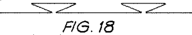
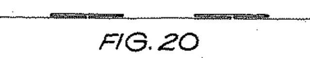
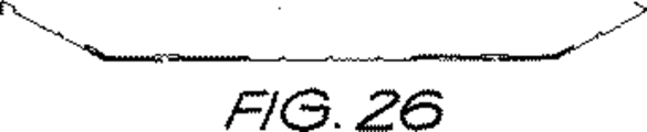
図2〜37は、梁40を形成するために金属42の部材に施される順次ロール成形段階を示す。図38は、図2〜21に示したロール成形段階と同等のロール成形花式図である。図39は、図22〜37に示したロール成形段階と同等の別のロール成形花式図である。ロール成形図および花式図はそれ自体説明を要しないと考えられるが、ロール成形作業の一般的な説明は以下の通りである。
2 to 37 show the sequential roll forming steps applied to the
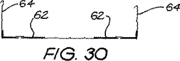
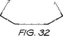
まず、金属42の平坦な部材が図11に示した形状にロール成形される。この形状は、それぞれが基部60aおよび2つの側部60bを有する、一対の離間されたチャネル60を有している。次に、チャネルの基部60aが、基部60aの下側に側部60bを折り畳むことにより(図21参照)、金属部材42の残りの部分に対して側部を挟んで平坦化され、3層構造の平坦化部62を形成する。次に、金属部材42の外側縁部64が平坦化部62に対して略直角に、平坦化部62の外側縁部に近づくように折り曲げられ、図30に示す形状となる。次に、折り曲げられた金属部材42の外側縁部64が平坦化部62の内側縁部に近づくように折り曲げられて、図36に示す略矩形形状を形成する。次に、金属部材42の2つの縦方向の縁部42aおよび42bが(図1に最も良く示したように)継ぎ目52内に折り畳まれて、図37に示す矩形梁40を形成する。
First, the flat member of the
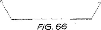
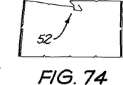
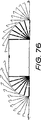
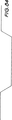
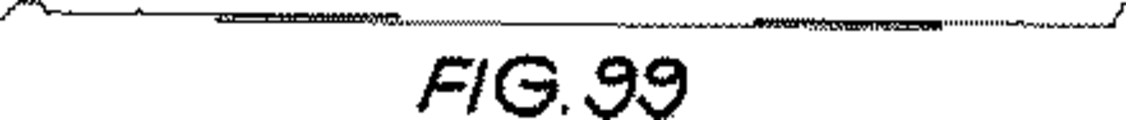
図40〜77は、梁70の第2の実施形態およびそのロール成形方法を示す。梁10の第1の実施形態と同じ特徴は、同じ参照番号で示されている。梁70は、3層構造の上下壁部72および74が、それぞれ全幅の外層72a、74aと、2つの中間および内半層72b、74bおよび72c、74cとからなる点で、梁10と異なる。
40 to 77 show a second embodiment of the
図78〜115は、梁80の第3の実施形態およびそのロール成形方法を示す。梁10の第1の実施形態と同じ特徴は、同じ参照番号で示されている。梁80は、3層構造の上下壁部82および84が、それぞれ3つの全幅の外層82a、82b、82cおよび84a、84b、84cとからなる点で、梁10と異なる。
78 to 115 show a third embodiment of the
図116は、梁90の第4の実施形態である。梁10の第1の実施形態と同じ特徴は、同じ参照番号で示されている。梁90は、3層構造(図1の領域58を参照)が内側の隅部を曲がって延びていない点で、梁10と異なる。
FIG. 116 is a fourth embodiment of the beam 90. The same features as the first embodiment of the beam 10 are indicated with the same reference numerals. The beam 90 differs from the beam 10 in that the three-layer structure (see
上記の梁の実施形態は、既知の2部構成の梁に対して多くの利点を有する。まず、それらは若干重いが、この梁は、相当するサイズの2部材梁よりも50〜100%長い距離をわたすことができる。2番目に、この梁は相当するサイズの既知の2部材梁と比較して改善されたねじれ剛性を有する。3番目に、この梁は1人の作業者、単独のロール成形作業によって製造が可能であり、結果として、より低い労働コスト、より低いプラントコスト、および低減されたマニュアルハンドリングがもたらされる。4番目に、この梁は、それ以上の表面加工を必要としないプレコート金属製品を含む各種材料から製造可能である。最後に、この梁は、スチールまたは木材梁の外観を再現し、かつ継ぎ目をカモフラージュする働きを兼ねたくぼみにより審美的に美しい。 The beam embodiment described above has many advantages over known two-part beams. First, they are slightly heavier, but this beam can span a distance 50-100% longer than a correspondingly sized two-member beam. Second, the beam has improved torsional rigidity compared to a known two-member beam of comparable size. Third, the beam can be manufactured by one worker, a single roll forming operation, resulting in lower labor costs, lower plant costs, and reduced manual handling. Fourth, the beam can be manufactured from a variety of materials including pre-coated metal products that do not require further surface processing. Finally, the beam is aesthetically pleasing due to the indentation that reproduces the appearance of a steel or wood beam and also serves as a camouflage for the seam.
本発明は特定の例に関連して説明されてきたが、当業者には本発明を多くの他の形状で実施可能であることが理解されよう。 Although the invention has been described with reference to specific examples, those skilled in the art will recognize that the invention can be implemented in many other forms.
本発明の好ましい実施形態は、一例として、添付の図面に関連してここに説明される。
Claims (20)
前記金属部材の少なくとも3つの隣接する層で形成された、対向する第1および第2の略平行な壁部と、
第1および第2の壁部の間の対向する第3および第4の略平行な壁部であって、第3または第4の壁部の一方が金属部材の2つの対向する縦方向の縁部を接合する継ぎ目を有する壁部と、を備える梁。A roll-formed beam having a substantially rectangular cross section formed from a single metal member,
Opposing first and second generally parallel walls formed of at least three adjacent layers of the metal member;
Opposing third and fourth substantially parallel wall portions between the first and second wall portions, one of the third or fourth wall portions being two opposing longitudinal edges of the metal member And a wall portion having a seam for joining the portions.
前記金属部材に、前記金属の少なくとも3つの層の一対の離間された平坦化部分を形成し、
金属部材の外側縁部を、平坦化部分の最外端に近づくように平坦化部分と約直角に折り曲げ、
折り曲げられた金属部材の外側縁部を、平坦化部分の最内端に近づくように平坦化部分と約直角に折り曲げ、
金属部材の隣接する最の外側の縦方向の縁部間の接合継ぎ目を折畳む順次ステップを含む方法。A method of roll-forming a beam having a substantially rectangular cross section from a single member of a substantially flat metal,
Forming a pair of spaced planarized portions of at least three layers of the metal on the metal member;
Bend the outer edge of the metal member approximately perpendicular to the flattened portion so as to approach the outermost end of the flattened portion;
Bend the outer edge of the bent metal member approximately perpendicular to the flattened portion so as to approach the innermost end of the flattened portion;
A method comprising sequential steps of folding a joint seam between adjacent outermost longitudinal edges of a metal member.
Applications Claiming Priority (2)
| Application Number | Priority Date | Filing Date | Title |
|---|---|---|---|
| AU2002952221A AU2002952221A0 (en) | 2002-10-23 | 2002-10-23 | A beam |
| PCT/AU2003/001402 WO2004038122A1 (en) | 2002-10-23 | 2003-10-22 | A beam |
Publications (3)
| Publication Number | Publication Date |
|---|---|
| JP2006504004A JP2006504004A (en) | 2006-02-02 |
| JP2006504004A5 JP2006504004A5 (en) | 2010-02-25 |
| JP4469722B2 true JP4469722B2 (en) | 2010-05-26 |
Family
ID=28795618
Family Applications (1)
| Application Number | Title | Priority Date | Filing Date |
|---|---|---|---|
| JP2004545602A Expired - Lifetime JP4469722B2 (en) | 2002-10-23 | 2003-10-22 | Beam |
Country Status (12)
| Country | Link |
|---|---|
| US (1) | US20060225476A1 (en) |
| EP (1) | EP1554444A4 (en) |
| JP (1) | JP4469722B2 (en) |
| KR (1) | KR20050063787A (en) |
| CN (1) | CN100422472C (en) |
| AU (1) | AU2002952221A0 (en) |
| BR (1) | BR0315564A (en) |
| CA (1) | CA2503496A1 (en) |
| MX (1) | MXPA05004317A (en) |
| NZ (1) | NZ540132A (en) |
| WO (1) | WO2004038122A1 (en) |
| ZA (1) | ZA200504152B (en) |
Families Citing this family (7)
| Publication number | Priority date | Publication date | Assignee | Title |
|---|---|---|---|---|
| WO2009084940A1 (en) * | 2007-12-31 | 2009-07-09 | Hong Liang Ng | Roll forming apparatus |
| JP6312366B2 (en) * | 2013-03-26 | 2018-04-18 | 大和ハウス工業株式会社 | Underfloor beam material and underfloor beam support structure |
| WO2015004586A2 (en) * | 2013-07-12 | 2015-01-15 | Jimenez Torres Hector | Strengthened structural profile comprising ribbing on all sides |
| CN104741480A (en) * | 2015-01-22 | 2015-07-01 | 苏州华源包装股份有限公司 | Can sealing technology for tank containing aqueous solution |
| JP6710571B2 (en) * | 2016-04-22 | 2020-06-17 | 西松建設株式会社 | Base material and partition wall |
| CN110560523A (en) * | 2019-09-20 | 2019-12-13 | 厦门绿世界温室工程技术有限公司 | Production equipment of greenhouse rod piece |
| RU208780U1 (en) * | 2021-09-08 | 2022-01-13 | Амир Равилевич Юскин | LONG-DIMENSIONAL BOX PROFILE |
Family Cites Families (16)
| Publication number | Priority date | Publication date | Assignee | Title |
|---|---|---|---|---|
| US2975874A (en) * | 1958-04-01 | 1961-03-21 | Pagan Alberto | Girder made up of structural members |
| US3043408A (en) * | 1959-03-23 | 1962-07-10 | Warren R Attwood | Metallic framing element |
| US3134468A (en) * | 1959-12-28 | 1964-05-26 | Andrew J Toti | Structural unit and assembly thereof |
| FR2265938A1 (en) * | 1974-03-13 | 1975-10-24 | Scanovator Ab | Constructional sheet metal hollow member - stiffened by forming groove down each side with free edges connected |
| BE891445A (en) * | 1981-12-11 | 1982-03-31 | Polypal | TUBULAR PROFILE WITH BOX SECTION. |
| GB2235712A (en) * | 1989-09-05 | 1991-03-13 | Metsec Plc | Structural beams |
| US5095678A (en) * | 1991-01-23 | 1992-03-17 | Steelway Housing | Structural stud |
| WO1993015353A1 (en) * | 1992-01-24 | 1993-08-05 | Rmt Pty. Ltd. | Element for composite structural member |
| DE19743643A1 (en) * | 1997-10-02 | 1999-04-08 | Meta Regalbau Gmbh & Co Kg | Steel beam profile |
| CN2353820Y (en) * | 1998-06-09 | 1999-12-15 | 林栋梁 | Combined wall plate |
| GB2371816B (en) * | 2001-01-31 | 2005-09-07 | Hong Liang Ng | Building material |
| US6415576B1 (en) * | 2000-09-25 | 2002-07-09 | Gustav M. Stromback | Reinforcing ridge apparatus and method |
| IT250679Y1 (en) * | 2000-11-17 | 2003-09-24 | Torri Spa | BEAM FOR METAL SHELVING |
| IT1319711B1 (en) * | 2000-12-29 | 2003-11-03 | Antonello Briosi | SUPPORTING STRUCTURE ELEMENT, SPECIES FOR SHELVING |
| ITUD20010073A1 (en) * | 2001-04-19 | 2002-10-19 | Danilo Giannini | BEAM FOR SUPPORTS AND RELEVANT REALIZATION PROCEDURE |
| JP2007534868A (en) * | 2004-04-29 | 2007-11-29 | マルティネス−セペダ,フェデリコ | Reinforced profile with groove |
-
2002
- 2002-10-23 AU AU2002952221A patent/AU2002952221A0/en not_active Abandoned
-
2003
- 2003-10-22 WO PCT/AU2003/001402 patent/WO2004038122A1/en active Application Filing
- 2003-10-22 BR BR0315564-1A patent/BR0315564A/en not_active IP Right Cessation
- 2003-10-22 JP JP2004545602A patent/JP4469722B2/en not_active Expired - Lifetime
- 2003-10-22 CA CA002503496A patent/CA2503496A1/en not_active Abandoned
- 2003-10-22 NZ NZ540132A patent/NZ540132A/en not_active IP Right Cessation
- 2003-10-22 CN CNB200380107438XA patent/CN100422472C/en not_active Expired - Fee Related
- 2003-10-22 US US10/532,324 patent/US20060225476A1/en not_active Abandoned
- 2003-10-22 MX MXPA05004317A patent/MXPA05004317A/en not_active Application Discontinuation
- 2003-10-22 KR KR1020057007011A patent/KR20050063787A/en not_active Application Discontinuation
- 2003-10-22 EP EP03757529A patent/EP1554444A4/en not_active Withdrawn
-
2005
- 2005-05-23 ZA ZA200504152A patent/ZA200504152B/en unknown
Also Published As
| Publication number | Publication date |
|---|---|
| CN1732318A (en) | 2006-02-08 |
| JP2006504004A (en) | 2006-02-02 |
| NZ540132A (en) | 2006-10-27 |
| WO2004038122A1 (en) | 2004-05-06 |
| AU2002952221A0 (en) | 2002-11-07 |
| EP1554444A4 (en) | 2007-07-11 |
| US20060225476A1 (en) | 2006-10-12 |
| MXPA05004317A (en) | 2005-12-05 |
| CN100422472C (en) | 2008-10-01 |
| ZA200504152B (en) | 2006-07-26 |
| KR20050063787A (en) | 2005-06-28 |
| CA2503496A1 (en) | 2004-05-06 |
| EP1554444A1 (en) | 2005-07-20 |
| BR0315564A (en) | 2005-08-23 |
Similar Documents
| Publication | Publication Date | Title |
|---|---|---|
| RU2588908C2 (en) | System and method of producing cellular plate | |
| CA2652919C (en) | Metal stud | |
| CN101605951B (en) | Grid tee and its construction method | |
| US7665259B2 (en) | Built-up rectangular steel column for filling concrete therein having L-shaped members and steel plates with curving projections and convex embossed portions | |
| JP5255840B2 (en) | Architectural panels and building structures | |
| JPH0321750A (en) | Building unit for molding metallic sheet and manufacture thereof | |
| WO1998048138A1 (en) | Metal beams with thermal break and methods | |
| CN104018609B (en) | Single-layered web beam for plaster tablet suspended ceiling | |
| US7895807B2 (en) | Segmented composite panel with false joints | |
| ZA200504152B (en) | A beam | |
| GB2235712A (en) | Structural beams | |
| US6574938B1 (en) | Constructional sandwich panel for high strength wall and covering assemblies, and method for making said panel | |
| AU2003273613B2 (en) | A beam | |
| JP2006504004A5 (en) | ||
| AU2011253543B2 (en) | System and Method for Manufacturing Cellular Board | |
| JP4545228B1 (en) | Rebound lightweight H-section steel | |
| WO1992021913A1 (en) | Steel beam and method of fabrication | |
| WO1999067478A1 (en) | Elongate structural member | |
| JP6692511B1 (en) | Sound absorbing panel and method for manufacturing sound absorbing panel | |
| GB2270706A (en) | Light weight metal beam | |
| AU2011253738B2 (en) | Method for Manufacturing Cellular Board and a Cellular Board | |
| JPH06346552A (en) | Building structural member and its manufacture |
Legal Events
| Date | Code | Title | Description |
|---|---|---|---|
| A621 | Written request for application examination |
Free format text: JAPANESE INTERMEDIATE CODE: A621 Effective date: 20060925 |
|
| A131 | Notification of reasons for refusal |
Free format text: JAPANESE INTERMEDIATE CODE: A131 Effective date: 20090630 |
|
| A601 | Written request for extension of time |
Free format text: JAPANESE INTERMEDIATE CODE: A601 Effective date: 20090930 |
|
| A602 | Written permission of extension of time |
Free format text: JAPANESE INTERMEDIATE CODE: A602 Effective date: 20091007 |
|
| A524 | Written submission of copy of amendment under article 19 pct |
Free format text: JAPANESE INTERMEDIATE CODE: A524 Effective date: 20100104 |
|
| TRDD | Decision of grant or rejection written | ||
| A01 | Written decision to grant a patent or to grant a registration (utility model) |
Free format text: JAPANESE INTERMEDIATE CODE: A01 Effective date: 20100202 |
|
| A01 | Written decision to grant a patent or to grant a registration (utility model) |
Free format text: JAPANESE INTERMEDIATE CODE: A01 |
|
| A61 | First payment of annual fees (during grant procedure) |
Free format text: JAPANESE INTERMEDIATE CODE: A61 Effective date: 20100301 |
|
| R150 | Certificate of patent or registration of utility model |
Free format text: JAPANESE INTERMEDIATE CODE: R150 |
|
| FPAY | Renewal fee payment (event date is renewal date of database) |
Free format text: PAYMENT UNTIL: 20130305 Year of fee payment: 3 |