JP4469520B2 - Reactor piping seal device, its handling tool, and reactor piping seal method - Google Patents
Reactor piping seal device, its handling tool, and reactor piping seal method Download PDFInfo
- Publication number
- JP4469520B2 JP4469520B2 JP2001216241A JP2001216241A JP4469520B2 JP 4469520 B2 JP4469520 B2 JP 4469520B2 JP 2001216241 A JP2001216241 A JP 2001216241A JP 2001216241 A JP2001216241 A JP 2001216241A JP 4469520 B2 JP4469520 B2 JP 4469520B2
- Authority
- JP
- Japan
- Prior art keywords
- reactor
- pressure vessel
- reactor pressure
- procedure
- annulus
- Prior art date
- Legal status (The legal status is an assumption and is not a legal conclusion. Google has not performed a legal analysis and makes no representation as to the accuracy of the status listed.)
- Expired - Fee Related
Links
Images


Classifications
-
- Y—GENERAL TAGGING OF NEW TECHNOLOGICAL DEVELOPMENTS; GENERAL TAGGING OF CROSS-SECTIONAL TECHNOLOGIES SPANNING OVER SEVERAL SECTIONS OF THE IPC; TECHNICAL SUBJECTS COVERED BY FORMER USPC CROSS-REFERENCE ART COLLECTIONS [XRACs] AND DIGESTS
- Y02—TECHNOLOGIES OR APPLICATIONS FOR MITIGATION OR ADAPTATION AGAINST CLIMATE CHANGE
- Y02E—REDUCTION OF GREENHOUSE GAS [GHG] EMISSIONS, RELATED TO ENERGY GENERATION, TRANSMISSION OR DISTRIBUTION
- Y02E30/00—Energy generation of nuclear origin
- Y02E30/30—Nuclear fission reactors
Landscapes
- Monitoring And Testing Of Nuclear Reactors (AREA)
Description
【0001】
【発明の属する技術分野】
本発明は、沸騰水型原子炉(以下、BWRという。)の原子炉内構造物の保全作業時であって、例えばシュラウド交換作業を行なう際に作業員の放射線被曝量の低減に好適な原子炉内配管シール装置とその取扱具および原子炉内配管シール方法に関する。
【0002】
【従来の技術】
従来、BWRでは出力密度を大きくするために原子炉圧力容器外部に設置した再循環ポンプと原子炉圧力容器内部に設けたジェットポンプとを組合せた、いわゆるジェットポンプシステムが採用されている。以下、まずこのジェットポンプシステムを採用したBWRについて図7および図8を参照して説明する。
【0003】
図7は、原子炉圧力容器の全体構成を示す縦断面図である。原子炉圧力容器1内に炉心シュラウド2が配置され、この炉心シュラウド2がシュラウドサポートシリンダ3によって支持されている。シュラウドサポートシリンダ3は、シュラウドサポートレグ4によって原子炉圧力容器1の底部に支持されている。炉心シュラウド2の上部には上部格子板5が設けられ、下部には炉心支持板6が設けられている。炉心シュラウド2の外周側にはジェットポンプ7が設けられ、このジェットポンプ7はジェットポンプディフューザ7a,ジェットポンプライザ管7b,ジェットポンプインレットミキサ7cにより構成されている。ジェットポンプ7の下方にはバッフルプレート8が、原子炉圧力容器1と炉心シュラウド2によって構成されるアニュラス部の全周にわたって設けられている。
【0004】
また、炉心シュラウド2内には、上部格子板5と炉心支持板6に挟まれるようにして燃料集合体10が設けられ、その燃料集合体10間には原子炉出力を制御する制御棒9が挿脱可能に設けられている。原子炉出力を上げる際には制御棒9が引き抜かれるが、その引き抜かれた制御棒9は燃料集合体10下方に設けられた円筒状の制御棒案内管11に納められる。
【0005】
一方、炉心シュラウド2の上方には、炉心スプレイ配管12,炉心スプレイスパージャ13,蒸気乾燥器15,気水分離器兼シュラウドヘッド16等の機器が設けられているが、これらの機器の機能については後述する。
【0006】
なお、符号17で示される構造物は原子炉圧力容器1の上蓋であり、これら原子炉圧力容器1と上蓋17は図示しない原子炉格納容器内の空間19に設置される。制御棒9は制御棒駆動機構(以下、CRDという。)20によって燃料集合体10間に挿脱され、このCRD20は制御棒駆動機構ハウジング(以下、CRDハウジングという。)21内に収納されている。原子炉圧力容器1内には冷却材23が注入され、炉心シュラウド2内に導かれて燃料集合体10と制御棒9で構成される炉心24を冷却する。
【0007】
冷却材23は、給水ノズル22によって原子炉圧力容器1内に導かれ炉心シュラウド2外を下降し、シュラウドサポートレグ4間を通過して炉心24を上昇する。その際、炉心24の核反応熱により昇温されて水と蒸気との二相流状態となる。二相流状態となった冷却材23は、炉心24の上方に設置された気水分離器兼シュラウドヘッド16内に流入し、そこで水と蒸気とに分離される。このうち、蒸気は気水分離器兼シュラウドヘッド16の上方に設置された蒸気乾燥器15内に導入され乾燥蒸気となる。
【0008】
この乾燥蒸気は、原子炉圧力容器1に接続された主蒸気ノズル14を介して図示しない上記タービンに移送され発電に供される。一方、分離された水は原子炉圧力容器1と炉心シュラウド2間のアニュラス部のいわゆるダウンカマ部を流れてシュラウドサポートレグ4間から再び炉心24の下方に流入する。
【0009】
ダウンカマ部内には、ジェットポンプ7が周方向に等間隔で複数設置される一方、原子炉圧力容器1の外部には、図示しない再循環ポンプが設置されており、この再循環ポンプ,ジェットポンプ7,およびこれら両者を接続する再循環配管により再循環系が構成されている。そして、再循環ポンプによりジェットポンプ7に駆動水が供給され、このジェットポンプ7の作用により冷却材23が炉心24内に強制循環される。
【0010】
炉心スプレイスパージャ13は、再循環配管破断によって発生する可能性のある冷却材喪失事故を未然に防ぐように図示しないサプレッションプールの水を炉心24内に注入するために設置される。この炉心スプレイスパージャ13は、冷却水を炉心24内に均一に注入できるように燃料集合体10上端部よりも上方の上部胴内面に周状に設置される。
【0011】
この炉心スプレイスパージャ13は、半円状のパイプで構成されており、180度対象の位置に1系統あたり2個設けられており、炉心シュラウド2内には安全設計上、2系統で4個設置されている。また、炉心スプレイスパージャ13は、パイプの外側円周部が炉心シュラウド2上部同内面と接するように図示しないブラケットにより固定されている。また、炉心シュラウド2の上部リングの内径は、炉心スプレイスパージャ13の外径より小径となっている。
【0012】
一方、ジェットポンプ7は、大量の冷却材に大きな吐出圧を与えて強制循環させるために、他の機器に比較すると厳しい状況下で使用される。従って、各構成部材には大きな負荷が作用する。
【0013】
特に図8に要部を拡大して示すように、ジェットポンプライザ管7bをその中間にて支持するライザブレース40には厳しい応力が作用することになる。
【0014】
ジェットポンプ7は、原子炉圧力容器1内部に固着されたジェットポンプライザ管7bを有しており、端部は再循環入口ノズル33に接続されている。原子炉圧力容器1内に存在する冷却材23の一部は前述の再循環系に抽出され、再循環ポンプの再循環入口ノズル33からジェットポンプライザ管7bを経由してジェットポンプ7の駆動水として利用されることになる。ジェットポンプライザ管7bの上部には、トランジションピース34を介して一対のエルボ35a,35bが接続されている。
【0015】
これらのエルボ35a,35bには、それぞれ一対の混合ノズル36a,36bを介して一対のインレットスロート37a,37bが接続されている。この一対のインレットスロート37a,37bにはそれぞれディフューザ38a,38bが接続されている。
【0016】
そして、混合ノズル36a,36bにより再循環系を経由して駆動水として供される冷却材23の一部が噴射され、その際周囲から冷却材23が巻き込まれる。これらの駆動水および巻き込まれた冷却材23は、インレットスロート37a,37b内部で混合され、その後ディフューザ38a,38bにより静水頭の回復がなされる。
【0017】
ところで、前記ジェットポンプ7においては、再循環ポンプから送り込まれる冷却材23の流れにより流体振動が発生する。この流体振動に対処するためにジェットポンプライザ管7bは前述したようにその下端を再循環入口ノズル33に溶着させており、上端はライザブレース40を介して原子炉圧力容器1に固定されている。
【0018】
また、インレットスロート37a,37bは、前述したようにその上端を混合ノズル36a,36b、およびベントを介してトランジションピース34に機械的に接続されるとともに、その下端はディフューザ38a,38bの上端に挿入されている。このようにジェットポンプライザ管7bおよびインレットスロート37a,37bは、ともに流体振動に十分対処可能に構成されている。
【0019】
次いで、混合ノズル36a,36bの上方の構成について説明すると、トランジションピース34の両側には、一対の耳部41がそれぞれ形成されおり、これらの耳部41は上方に突出し、その上端部の内側には溝部42が形成されている。この溝部42には、長手方向中央部に沿って増大する長方形断面を有する一対のジェットポンプビーム43の両端部が嵌合して固定されている。
【0020】
ジェットポンプビーム43の中央には、鉛直方向に図示しないネジ穴が穿設されており、このネジ穴にヘッドボルト44が螺合している。このヘッドボルト44の上端には六角頭が形成されており、また下端には半丸頭が形成されている。
【0021】
一方、エルボ35a,35bには、図示しないが上端面が水平な台座部が形成されており、この台座部には図示しない座ぐり穴が形成されている。この座ぐり穴内には球面座金を介してヘッドボルト44の半丸頭が嵌合している。
【0022】
なお、インレットスロート37a,37bは原子炉圧力容器1に固着されていないため、その上端部およびエルボ35a,35bにはジェットポンプライザ管7bを介して供給される駆動水の流入水圧が作用する。
【0023】
また、エルボ35a,35bの他端に接続する図示しないノズルからディフューザ38a,38b内に向かって噴出される駆動水の噴出水圧などの反力が上向きに作用する。この荷重に対抗するためにヘッドボルト44がジェットポンプビーム43に螺合される。
【0024】
なお、耳部41が固定されているので、ヘッドボルト44を回転させると、ジェットポンプビーム43の上方向に移動し、その両端は溝部42の上壁面に当接した状態となる。これにより、上向きの荷重を受ける。
【0025】
これとは逆に、エルボ35a,35bの上端部には、ヘッドボルト44を介して下向きの荷重が加わり、その大きさは駆動水の反力などによる上向きの荷重により決定される。ヘッドボルト44の六角頭には図示しないキーパが着脱自在に嵌合している。このキーパは指示しない支持板上に点溶接により固着されている、この支持板は四角形をなしており、2本のボルトによりジェットポンプビーム43の上面に固定される。
【0026】
インレットスロート37a,37bは、ジェットポンプライザ管7bに固着したライザーブランケット45に取り付けられている。また、ディフューザ38a,38bは、原子炉圧力容器1に溶着されているバッフルプレート46に固定されている。
【0027】
ライザーブレース40は、ジェットポンプライザ管7bに発生する原子炉運転中の流体振動を制御するとともに、炭素鋼である原子炉圧力容器1とオーステナイト系ステンレス鋼製であるジェットポンプライザ管7bとの間の熱膨張差を吸収する。したがって、原子炉運転中には、上記熱膨張差を吸収した状態で変形状態にある。
【0028】
ところで、原子力プラントの出力制御を行なう上で、通常運転中のジェットポンプ流量を測定することは重要であり、このためディフューザ38a,38bの上下部に測定用配管39を設けて、運転中のディフューザ38a,38bの上下部の静圧差を測定し、この測定値をプラント使用前に測定した較正値とによりジェットポンプ流量を算出している。
【0029】
この測定用配管39はディフューザ38a,38bの上下部の静孔に溶接され、ディフューザ38a,38bに固着されているサポート47により溶接支持され、さらにジェットポンプ7の下部に配置され、ジェットポンプ計測用ノズルを経て原子炉外配管と接続されている。
【0030】
このジェットポンプ計測用ノズルは、原子炉圧力容器1に対称位置に2個所設けられている。このような構成のジェットポンプ7は、再循環ポンプから送り込まれる駆動水の流れにより、他の機器に比較して厳しい条件下で使用される。このため、各部材には大きな負荷が作用し、流体振動の影響を受け、厳しい応力が作用することとなり、したがって配管破断を生じることが十分予想される。
【0031】
一方、炉心シュラウド2を構成するカーボン含有量が高いステンレス鋼等の金属材料は高温水中に置かれた場合、溶接部やその近傍の溶接熱影響部に応力腐食割れ(以下、IGSCCという。)が発生することが一般に知られている。このIGSCCは、材料,応力および環境の3つの発生原因が重畳した条件下で発生することが知られている。材料要因としてはクロム(Cr)炭化物が結晶粒界へ折出し、その周辺に耐食性の劣るCr欠乏層が形成されることによる材料の鋭敏化が上げられ、応力要因としては溶接や加工により材料内部に残留する引張残留応力が上げられる。また、環境要因としては高温水中に存在する溶存酸素量などが上げられる。IGSCCは、材料,応力および環境の3つの発生要因から1つの発生要因を取り除けば発生を防止できる。
【0032】
炉心シュラウド2はステンレス鋼部材を周溶接および縦溶接により円筒状構造物に構成したものである。炉心シュラウド2はステンレス鋼の炭素含有量が高いと、溶接部あるいはその近傍に応力腐食割れ等によるクラックが発生するおそれがある。原子炉は、一般に、三重、四重あるいはそれ以上の多重防護策を施し、安全性の確保に万全の体制を敷いている。原子炉の炉心シュラウド2に万一、クラックのような事象が発生した場合には、原子炉の安全性のために炉心シュラウド2の補修あるいは取換えを行なう必要がある。また、この炉心シュラウド2内部に設置された原子炉内構造物も同様に不具合を生じた場合には、それを補修あるいは交換する必要がある。
【0033】
このような事象が生じた場合、例えば炉心シュラウドの溶接部を補修する方法としては、特開平5−323078号公報に開示されたものがある。本公報には、炉心シュラウド2表面から超音波探傷試験装置により溶接部の検査を行う第1の手順と、その検査により割れ部が発見された場合その割れ部の補修加工を行う第2の手順と、前記補修加工の後加工部の表面改質処理を行う第3の手順とを有する炉心シュラウド溶接部の補修方法の記載がある。
【0034】
【発明が解決しようとする課題】
しかしながら、長期間使用された原子炉の炉心シュラウドは炉心からの中性子照射を受けて脆化しており、溶接接合された炉心シュラウドは、溶接金属(溶接部)の周辺にさらに細かい割れが生じることがあるため、溶接による炉心シュラウドの補修は困難であり、それゆえ長時間作業の必要性もある。さらに、原子炉の安全性にとって最も望ましい方法は、不具合の生じた原子炉内構造物や炉心シュラウドを新しい構造物あるいは炉心シュラウドに交換することである。しかし、原子炉内に据付けられた構造物や炉心シュラウドを撤去して新しい構造物や炉心シュラウドを据付けることは補修に比べてさらに困難であるため、構造物や炉心シュラウドの交換を行う際には、原子炉内の高放射線環境下での長時間作業が不可避であり、作業員の安全管理上好ましくない。
【0035】
本発明は、上述した事情を考慮してなされたもので、原子炉圧力容器内の構造物や炉心シュラウドの補修あるいは交換を行う際に、原子炉圧力容器と炉心シュラウド間に形成されるアニュラス部に水を張り、この水によって原子炉圧力容器などから放出される放射線を遮蔽して、作業員が原子炉内に入域しても安全に作業が行えるように原子炉内配管シール装置とその取扱具および原子炉内配管シール方法を提供することにある。
【0036】
【課題を解決するための手段】
上記目的を達成するために請求項1に記載の発明は、原子炉圧力容器と原子炉圧力容器内底部に溶接固定された炉心シュラウドによって構成されるアニュラス部に設けられた原子炉内配管の開口部に設置される原子炉内配管シール装置において、前記原子炉配管の開口部に挿入される固定部と、この固定部に設けられたシャフトと、このシャフトに貫挿される移動部と、この移動部と前記固定部間に介挿されるシール部と、前記シャフトに螺設されるナットと、前記移動部の外側の外周部近傍に設けられ取扱具を把持するツバ部とを有する。
【0037】
また、請求項2記載の発明は、請求項1記載の原子炉内配管シール装置において、前記ツバ部と一体をなす前記開口部内径よりも大きな外径を有するストッパを有するものである。
【0038】
請求項3記載の発明は、請求項1乃至請求項2記載の原子炉内配管シール装置のツバ部に係合する固定爪と、移動爪と、この移動爪を駆動して前記ツバ部に係合させる可動シャフトとを有するものである。
【0039】
請求項4記載の発明は、請求項3記載の原子炉内配管シール装置の取扱具において、前記可動シャフトがネジ溝を介して螺合される二重円筒構造であって、内側シャフトを回転させて前記移動爪を駆動するものである。
【0040】
請求項5記載の発明は、原子炉圧力容器内に設けられた構造物の一部を前記原子炉圧力容器外に搬出する第1の手順と、前記原子炉圧力容器と前記原子炉圧力容器底部に溶接固定された炉心シュラウドによって構成されるアニュラス部に設けられた原子炉内配管の開口部を請求項1乃至請求2のシール装置及び請求項3乃至請求項4の取扱具を用いてシールする第2の手順と、前記アニュラス部に水を張る第3の手順とを有する。
【0041】
請求項6記載の発明は、原子炉圧力容器内に設けられた構造物の一部を前記原子炉圧力容器外に搬出する第1の手順と、原子炉圧力容器内底部に溶接固定された炉心シュラウドを撤去する第2の手順と、新たな炉心シュラウドを原子炉圧力容器内に搬入して前記原子炉圧力容器内底部に溶接固定する第3の手順と、前記原子炉圧力容器と前記原子炉圧力容器底部に溶接固定された炉心シュラウドによって構成されるアニュラス部に設けられた原子炉内配管の開口部を請求項1乃至請求2のシール装置及び請求項3乃至請求項4の取扱具を用いてシールする第4の手順と、前記アニュラス部に水を張る第5の手順とを有する。
【0042】
上記のように構成された請求項1に記載の発明においては、シール装置の移動部の外側の外周部近傍に設けられたツバ部に取扱具が係合され、シール装置の外側をほぼ全面で把持できることから、安定に支持できるため取り扱い操作が容易になるとともに遠隔操作で取り扱うことが可能となる。すなわち、原子炉内配管の開口部において、取扱具によりナットを回転させることによって、移動部が固定部側に押しやられ、移動部と固定部に挟まれたシール部が原子炉内配管内に密着される。それによって、原子炉配管内に漏れ出る水をなくし、炉心シュラウド外側に形成されるアニュラス部に水を張ることにより水遮蔽を形成させるものである。この水遮蔽によれば放射線被曝量を大幅に低減できることから、作業員が長時間安全に原子炉内で作業を行うことができる。また、移動部は、原子炉内配管開口端部より内側へ突出しないため、前記アニュラス部における作業を阻害することなく、作業の安全性、信頼性を向上させることができる。なお、シール部は固定部と移動部に挟まれるものであり交換可能であるため、シール部に摩耗などが生じても交換すればよく、原子炉内配管シール装置全体を交換する必要がないため経済的である。
【0043】
請求項2に記載の発明の構成要素であるストッパは、原子炉配管開口部の内径よりも大きな外径を有することでこの開口部に当接させるものである。従って、原子炉内配管シール装置が原子炉内配管内に入り込むことを防止できる。
【0044】
請求項3に記載の発明の構成要素である固定爪は、請求項1または請求項2に記載された発明のツバ部と係合する。また、可動シャフトは移動爪を駆動させて、前記ツバ部に係合させるものである。このようにすれば、原子炉内配管シール装置を脱落させることなく遠隔操作により把持することができる。従ってシール部材を原子炉内配管の開口部の近傍に確実にシールすることが可能となり、作業安全性、信頼性を向上させることができる。
【0045】
請求項4に記載の発明の構成要素である可動シャフトはネジ溝を介して螺合される二重円筒構造であり、内側シャフトを回転させて移動爪を駆動させる。従って、可動シャフトを直接的に例えば鉛直方向に移動させることによって移動爪を駆動させる場合よりも負荷が小さく容易に移動爪を前記ツバ部に係合できる。
【0046】
請求項5に記載の発明においては、第1の手順によって原子炉圧力容器内においてアニュラス部にアクセスすることが可能となり、また第2の手順によってシール装置を落下させることなく容易に安全に原子炉内配管をシールすることが可能となり、アニュラス部に水を張っても原子炉内配管を介してアニュラス部外に漏水することがなくなる。さらに第3の手順によっては水遮蔽を形成することが可能となり、原子炉内構造物やシュラウドの補修あるいは交換作業を放射線を遮蔽しながら安全に長時間でも実施することができる。
【0047】
請求項6に記載の発明においては、第1の手順によって原子炉圧力容器内においてアニュラス部にアクセスすることが可能となり、第2の手順によって交換が必要な炉心シュラウドが搬出され、第3の手順で新たに供される炉心シュラウドが設置される。この第3の手順が終了した段階で、再びアニュラス部が形成される。すなわち、新しい炉心シュラウドが溶接されるため、アニュラス部の底部から炉心シュラウド内部側に漏水することなくアニュラス部に水を張ることが可能となる。第4の手順では、シール装置を落下させることなく容易に安全に原子炉内配管をシールすることが可能となり、アニュラス部に水を張っても原子炉内配管を介してアニュラス部外に漏水することがなくなる。さらに第5の手順によっては水遮蔽を形成することが可能となり、シュラウド交換後の補修作業を放射線を遮蔽しながら安全に長時間でも実施することができる。
【0048】
【発明の実施の形態】
図1および図2を参照しながら本発明に係る原子炉内配管シール装置の第1および第2の実施の形態について説明する。(請求項1および請求項2に対応)
図1は第1および第2の実施の形態に係る原子炉内配管シール装置の断面図である。図2は炉心スプレイ系配管12内に設置された第1および第2の実施の形態に係る原子炉内配管シール装置の拡大断面図である。
【0049】
図1において、炉心スプレイ系配管12の開口部に、原子炉内配管シール装置50が組込まれている。原子炉圧力容器1と炉心シュラウド2との間に形成されるアニュラス部に水48を張って水遮蔽を行っている状態を示している。アニュラス部には水48の他に金属(鉛)製の遮蔽体51も据付けられている。金属製の遮蔽体51は重く設置作業が困難である上、アニュラス部のすき間を狭くするため作業性の悪い状態となっている。
【0050】
拡大断面図の図2において、符号52はシール部材であり、その両側は固定部である固定金具53と移動部である移動金具54に挟まれるようにして組込まれている。固定金具53の中央部にはシャフト55が一体に構成され、このシャフト55に移動金具54と締付ナット56が組込まれている。この締付ナット56を回転させることによってシール部材52が膨縮して機械的なシール効果を得ることができる。このシール部材52は固定金具53と移動金具54に挟まれる構造であるため交換可能である。従って、シール部材52が摩耗したり破損した場合においても、原子炉内配管シール装置50全体を交換する必要はなく原子炉内配管シール装置50を長期間供することができる。
【0051】
また、移動金具54の外側には第1および第2の実施の形態のシール装置50を把持するためのツバ部57が設けられ、後述する取扱具によって遠隔での着脱を自在に行うことができる。
【0052】
さらに、第2の実施の形態では、ツバ部57と一体にストッパ58が設けられている。このストッパ58の外径は炉心スプレイ配管12の開口部の内径よりも大きく設けられているため、原子炉内配管シール装置50が炉心スプレイ配管12の内部に入り込まないように防止できる。
【0053】
原子炉内配管シール装置50は炉心スプレイ配管12の開口部から移動金具54を配管内部に向かって移動させてシール部材52を膨縮させるため、炉心スプレイ配管12の開口部から突出しないように取り付けることができる。さらには、固定金具53および移動金具54は配管内部に向かって凸状、すなわち配管外部側から見れば凹状に形成されているため、原子炉内配管シール装置50を設置した場合にシャフト55や締付ナット56を炉心スプレイ配管12の開口部からアニュラス側に突出させないようにすることが可能であり、アニュラス部で行われる他の作業と干渉しない構造とすることができる。
【0054】
図3(a),(b)乃至図5を参照しながら本発明に係る原子炉配管シール装置の取扱具の第1の実施の形態について説明する。(請求項3および請求項4に対応)
図3(a)は第1の実施の形態に係る原子炉内配管シール装置の取扱具の正面図である。図3(b)はその側面図である。
【0055】
図3(a)および(b)において、取扱具59は2個の固定爪60と可動シャフト62によって上下に駆動する移動爪61を有している。また、可動シャフト62を容易に回転させるために、可動シャフト62の上端部にはハンドル63が設けられている。可動シャフト62は二重構造をとり、内側可動シャフト62aと外側可動シャフト62bは互いにネジ構造を有して嵌合している。固定爪60は下端部に設けられており、この固定爪60が原子炉内配管シール装置50のツバ部57の内側に係合する構造になっている。遠隔操作時には、まずこれらの固定爪60をツバ部57に係合させて、それから内側可動シャフト62aをハンドル63で回転させることによって上下動させ、移動爪61を連動させてツバ部57に係合させることによって原子炉内配管シール装置50を把持することができる。
【0056】
図4(a),(b)は原子炉内配管シール装置50の締付ナット56を締付けあるいは緩めるためのラチェットレンチを示すそれぞれ正面図と側面図である。
【0057】
図4(a)および(b)において、ラチェットレンチ64はその上部にポール66を有し、このポール66は締付ボルト67で取り付けられている。また、ラチェットレンチ64の下部にはソケット部65が設けられ原子炉内配管シール装置50の締付ナット56に係合する。締付ナット56に係合して、締付けや緩めが可能であれば、図4(a),(b)に示されるようなラチェットレンチ64に限定されないが、原子炉内配管シール装置50を原子炉内配管の開口部に設置する場合には、原子炉圧力容器1と炉心シュラウド2によって形成されるアニュラス部での作業が必要となるため、図示されるようなラチェットレンチ64が好適である。
【0058】
図5は原子炉内配管シール装置50に取扱具59を係合させたままラチェットレンチ64のソケット部65を締付ナット56にセットした状態を示す縦断面図である。ラチェットレンチ64の締付ナット56へのセットは常に取扱具59を介して行う必要はない。しかし、締付ナット56の締付けあるいは緩めを行う際に取扱具59を装着しておくことにより、締付けや緩めの作業が容易になる。例えば締付け作業の場合、シール部材52は配管内部でまだ締め付けられておらず、原子炉内配管シール装置50と配管内部とはいわば遊びがある状態である。従って、ラチェットレンチ64を締付ナット56に係合させようとした場合に安定性を欠く。原子炉内配管シール装置50を取扱具59によって原子炉配管内に挿入した後、取扱具59をそのまま装着しておけば、原子炉内配管シール装置50を安定に支持することができ、またアニュラス部への脱落も防止することができ、ラチェットレンチ64による締付ナット56締付作業が容易になる。
【0059】
一方、緩め作業の場合には、ラチェットレンチ64で緩める前に取扱具59を原子炉内配管シール装置50に係合すれば、締付ナット56が緩められた後で取扱具59を装着するよりも安定性があり容易であるし、締付け作業時と同様に原子炉内配管シール装置50の脱落も防止することができる。
【0060】
このように取扱具59は原子炉内配管への原子炉内配管シール装置50の脱着のみならず、安定的に固定するという効果も持たせることが可能である。このような効果を発揮させるためには、図3(a),(b)および図5に示すように取扱具59の側板68に例えばラチェットレンチ64のソケット部65が通過できるような穴を設ける必要がある。また、このようにした側板68にはソケット部65をセットするとき、位置決めのためのガイドの機能をも持たせることが可能である。
【0061】
以上のことから、好ましくは原子炉内配管シール装置50を着脱する場合にはレンチがない状態で行い、原子炉内配管シール装置50を原子炉内配管の開口部に押着後レンチを組込み、締付ナット56の締付けあるいは緩めを行なう。それにより、短時間で容易かつ確実に原子炉内配管シール装置50を遠隔で着脱することができる。
【0062】
次に、図6を参照しながら、本発明に係る原子炉内配管シール方法の第1および第2の実施の形態について説明する。(請求項5および請求項6に対応)
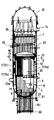
図6は原子炉圧力容器と一部の原子炉内構造物を示す部分断面図である。また、図6は、原子炉内配管シール装置50が取扱具59によって炉心スプレイ配管12内部に取り付けられ水遮蔽が完了した後に、作業員69が炉心シュラウド2内に入り作業をしている様子を示すものである。
【0063】
図6において、原子炉圧力容器1内にはシュラウドサポートレグ4にシュラウドサポートシリンダ3を介して新しい炉心シュラウド2が設けられており、原子炉圧力容器1と炉心シュラウド2で形成されるアニュラス部には水48が張られている。炉心スプレイスパージャ13に接続している炉心スプレイ配管12の開口部には、図示されていないが原子炉内配管シール装置50が設置されており、炉心スプレイ配管12内に水48が入り込まないようになっている。また、アニュラス部にはジェットポンプ7やディフューザ38がバッフルプレート8の上部にそのまま設置された状態にある。作業員69はCRDハウジング21上で作業を行っている。
【0064】
このように作業が行えるようにするためには、本実施の第1の実施の形態においては、まず原子炉圧力容器1と炉心シュラウド2で形成されるアニュラス部にアクセスできるように、例えば図7に示される蒸気乾燥器15や上部格子板5などの原子炉内構造物の一部を原子炉圧力容器1外に搬出する必要がある。その後、アニュラス部に設けられた原子炉内配管の開口部をシールして、炉心スプレイ配管12などの原子炉内配管を介して漏水する可能性を絶った後、炉心シュラウド2の上端近傍までアニュラス部に水48を張り水遮蔽を形成させるものである。このように水遮蔽を形成させることができれば、原子炉圧力容器1などからの放射線を遮蔽することができ、シュラウド内において原子炉内構造物の補修、交換などの作業が安全にそして長時間にわたって可能となる。
【0065】
次に本発明に係る第2の実施の形態は、特に炉心シュラウド2を新しいものに交換するような場合に好適である。炉心シュラウドを交換するような場合には、原子炉内構造物の一部を原子炉圧力容器1外に搬出した後、原子炉圧力容器1内底部に溶接固定された炉心シュラウド2を撤去する必要がある。その後、新たな炉心シュラウド2を原子炉圧力容器1内に搬入して原子炉圧力容器1内底部に再び溶接固定する。このように予め溶接しなければならないのは、新しい炉心シュラウド2と原子炉圧力容器1底部との間の隙間をなくし、アニュラス部に水を張った際に漏れないようにするためである。そして、原子炉圧力容器1と炉心シュラウド2によって構成されるアニュラス部に設けられた炉心スプレイ配管12の開口部をシールすることになる。その後、第1の実施の形態と同様にアニュラス部に水を張り水遮蔽を形成させる。ただ、この開口部のシールを新しい炉心シュラウド2の原子炉圧力容器1内底部への溶接前に実施し、その後炉心シュラウド2上端近傍まで水を張ったとしても水遮蔽の効果には変わりがない。
【0066】
【発明の効果】
本発明によれば、安定した原子炉内配管シール装置の遠隔操作による取り扱いが可能となり、さらにシール装置の落下を防止できる。また、原子炉内構造物や炉心シュラウドの交換作業および点検、補修作業を長時間でも安全に行なうことができ、さらにこれらの交換作業および点検補修作業を長時間でも安全に行うことができれば、原子力発電プラントを長期間にわたり継続して運転することができるという大きな効果がある。
【0067】
また、特に請求項2に記載の発明においては、原子炉内配管シール装置が原子炉内配管内に入り込むことを防止できる。
【0068】
請求項3,4に記載の発明においては、原子炉内配管シール装置を脱落させることなく遠隔操作により把持することができる。従って、シール部材によって原子炉内配管の開口部近傍を確実にシールすることができ、作業安全性、信頼性を向上させることができる。
【0069】
特に請求項4に記載の発明においては、可動シャフトを直接的に例えば鉛直方向に移動させることによって移動爪を駆動させる場合よりも負荷が小さく容易に移動爪を原子炉内配管シール装置のツバ部に係合させることができる。
【図面の簡単な説明】
【図1】請求項1および2に記載された発明の第1および第2の実施の形態に係る原子炉内配管シール装置の断面図である。
【図2】請求項1および2に記載された発明の第1および第2の実施の形態に係る原子炉内配管シール装置の拡大断面図である。
【図3】(a)は請求項3および4に記載された発明の第1の実施の形態に係る原子炉内配管シール装置の取扱具の正面図であり、(b)はその側面図である。
【図4】(a)は原子炉内配管シール装置の締付ナットを締付けあるいは緩めるラチェットレンチの正面図であり、(b)はその側面図である。
【図5】原子炉内配管シール装置に取扱具を係合させたままラチェットレンチのソケット部を締付ナットにセットした状態を示す縦断面図である。
【図6】請求項5および6に記載された発明の第1および第2の実施の形態に係る原子炉内配管シール方法について説明するための、原子炉圧力容器と一部の原子炉内構造物を示す部分断面図である。
【図7】従来技術を説明するための、原子炉圧力容器の全体構成を示す縦断面図である。
【図8】従来技術を説明するための、原子炉圧力容器内の一部を拡大して示す矢視断面図である。
【符号の説明】
1…原子炉圧力容器、2…炉心シュラウド、3…シュラウドサポートシリンダ、4…シュラウドサポートレグ、5…上部格子板、6…炉心支持板、7…ジェットポンプ、7a…ジェットポンプディフューザ、7b…ジェットポンプライザ管、7c…ジェットポンプインレットミキサ、8…バッフルプレート、9…制御棒、10…燃料集合体、11…制御棒案内管、12…炉心スプレイ系配管、13…炉心スプレイスパージャ、14…主蒸気ノズル、15…蒸気乾燥器、16…気水分離器兼シュラウドヘッド、17…上蓋、19…空間、20…制御棒駆動機構、21…制御棒駆動機構ハウジング、22…給水ノズル、23…冷却材、24…炉心、33…再循環入口ノズル、34…トランジションピース、35a,35b…エルボ、36a,36b…混合ノズル、37a,37b…インレットスロート、38,38a,38b…ディフューザ、39…計測用配管、40…ライザブレース、41…耳部、42…溝部、43…ジェットポンプビーム、44…ヘッドボルト、45…ライザブランケット、46…バッフルプレート、47…サポート、48…水、50…原子炉内配管シール装置、51…遮蔽体、52…シール部材、53…固定金具、54…移動金具、55…シャフト、56…締付ナット、57…ツバ部、58…ストッパ、59…取扱具、60…固定爪、61…移動爪、62…可動シャフト、62a…内側可動シャフト、62b…外側可動シャフト、63…ハンドル、64…ラチェットレンチ、65…ソケット部、66…ポール、67…締付ボルト、68…側板、69…作業員[0001]
BACKGROUND OF THE INVENTION
The present invention is an atom suitable for reducing the radiation exposure of workers during maintenance work of a reactor internal structure of a boiling water reactor (hereinafter referred to as BWR), for example, when performing shroud replacement work. The present invention relates to an in-reactor piping sealing device, a handling tool for the same, and a reactor in-pipe sealing method.
[0002]
[Prior art]
Conventionally, the BWR employs a so-called jet pump system in which a recirculation pump installed outside the reactor pressure vessel and a jet pump provided inside the reactor pressure vessel are combined in order to increase the power density. Hereinafter, a BWR employing this jet pump system will be described with reference to FIGS.
[0003]
FIG. 7 is a longitudinal sectional view showing the overall configuration of the reactor pressure vessel. A
[0004]
A
[0005]
On the other hand, above the
[0006]
In addition, the structure shown with the code |
[0007]
The
[0008]
The dry steam is transferred to the turbine (not shown) via the
[0009]
A plurality of
[0010]
The
[0011]
This
[0012]
On the other hand, the
[0013]
In particular, as shown in an enlarged view of the main part in FIG. 8, severe stress acts on the
[0014]
The
[0015]
A pair of
[0016]
Then, a part of the
[0017]
By the way, in the
[0018]
In addition, the
[0019]
Next, the configuration above the mixing
[0020]
A screw hole (not shown) is formed in the center of the
[0021]
On the other hand, although not shown, the
[0022]
Since the
[0023]
In addition, a reaction force such as the ejection pressure of driving water ejected from the nozzle (not shown) connected to the other end of the
[0024]
In addition, since the ear | edge
[0025]
On the contrary, a downward load is applied to the upper ends of the
[0026]
The
[0027]
The
[0028]
By the way, it is important to measure the flow rate of the jet pump during normal operation when controlling the output of the nuclear power plant. For this reason,
[0029]
The
[0030]
Two jet pump measurement nozzles are provided at symmetrical positions in the
[0031]
On the other hand, when a metal material such as stainless steel having a high carbon content that constitutes the
[0032]
The
[0033]
When such an event occurs, for example, a method for repairing the welded portion of the core shroud is disclosed in Japanese Patent Laid-Open No. 5-323078. This publication discloses a first procedure for inspecting a welded portion from the surface of the
[0034]
[Problems to be solved by the invention]
However, the core shroud of a nuclear reactor that has been used for a long period of time is embrittled by neutron irradiation from the core, and the core shroud that has been welded may cause finer cracks around the weld metal (welded part). Therefore, it is difficult to repair the core shroud by welding, and therefore there is a need for long working hours. Furthermore, the most desirable method for reactor safety is to replace a failed reactor internal structure or core shroud with a new structure or core shroud. However, it is more difficult to remove a structure or core shroud installed in the reactor and install a new structure or core shroud compared to repair, so when replacing the structure or core shroud Therefore, it is inevitable to work for a long time in a high radiation environment in a nuclear reactor, which is not preferable for safety management of workers.
[0035]
The present invention has been made in consideration of the above-described circumstances, and an annulus portion formed between the reactor pressure vessel and the core shroud when repairing or replacing the structure in the reactor pressure vessel or the core shroud. The reactor piping seal device and its device are designed to shield the radiation emitted from the reactor pressure vessel, etc. by this water, so that workers can work safely even if they enter the reactor. The object is to provide a handling tool and a method for sealing pipes in a nuclear reactor.
[0036]
[Means for Solving the Problems]
In order to achieve the above object, an invention according to
[0037]
Further, the invention according to
[0038]
The invention described in
[0039]
According to a fourth aspect of the present invention, in the handling tool of the in-reactor piping seal device according to the third aspect, the movable shaft is screwed through a thread groove, and the inner shaft is rotated. The moving claw is driven.
[0040]
The invention according to
[0041]
According to a sixth aspect of the present invention, there is provided a first procedure for carrying out a part of the structure provided in the reactor pressure vessel to the outside of the reactor pressure vessel, and a core fixed by welding to the bottom of the reactor pressure vessel. A second procedure for removing the shroud, a third procedure for carrying a new core shroud into the reactor pressure vessel and welding and fixing it to the bottom of the reactor pressure vessel, the reactor pressure vessel and the reactor Opening of the reactor piping provided in the annulus composed of the core shroud welded to the bottom of the pressure vessel Using the sealing device according to
[0042]
In the invention according to
[0043]
The stopper, which is a constituent element of the invention described in
[0044]
The fixing claw which is a component of the invention described in
[0045]
The movable shaft which is a constituent element of the invention described in claim 4 has a double cylindrical structure screwed through a thread groove, and drives the moving claw by rotating the inner shaft. Therefore, the moving claw can be easily engaged with the collar portion with a smaller load than when the moving claw is driven by moving the movable shaft directly in the vertical direction, for example.
[0046]
In the invention according to
[0047]
According to the sixth aspect of the present invention, it is possible to access the annulus portion in the reactor pressure vessel by the first procedure, and the core shroud that needs to be replaced is carried out by the second procedure. A new core shroud will be installed. When the third procedure is completed, the annulus portion is formed again. That is, since a new core shroud is welded, it is possible to fill the annulus with water without leaking from the bottom of the annulus to the inside of the core shroud. In the fourth procedure, Easily and safely without dropping the sealing device It is possible to seal the reactor internal pipe, and even if water is applied to the annulus part, water is not leaked outside the annulus part via the reactor internal pipe. Further, according to the fifth procedure, it becomes possible to form a water shield, and the repair work after the shroud replacement can be carried out safely and for a long time while shielding the radiation.
[0048]
DETAILED DESCRIPTION OF THE INVENTION
First and second embodiments of an in-reactor piping seal device according to the present invention will be described with reference to FIGS. 1 and 2. (Corresponding to
FIG. 1 is a cross-sectional view of an in-reactor piping seal device according to the first and second embodiments. FIG. 2 is an enlarged cross-sectional view of the reactor piping seal apparatus according to the first and second embodiments installed in the core spray system piping 12.
[0049]
In FIG. 1, an in-reactor
[0050]
In FIG. 2 of the enlarged sectional view,
[0051]
Further, a
[0052]
Furthermore, in the second embodiment, a
[0053]
The in-reactor
[0054]
A first embodiment of a handling tool for a reactor pipe sealing device according to the present invention will be described with reference to FIGS. 3 (a) and 3 (b) to FIG. (Corresponding to
FIG. 3A is a front view of the handling tool of the in-reactor piping seal device according to the first embodiment. FIG. 3B is a side view thereof.
[0055]
3A and 3B, the handling
[0056]
FIGS. 4A and 4B are a front view and a side view, respectively, showing a ratchet wrench for tightening or loosening the tightening
[0057]
4 (a) and 4 (b), the ratchet wrench 64 has a
[0058]
FIG. 5 is a longitudinal sectional view showing a state in which the
[0059]
On the other hand, in the case of the loosening operation, if the
[0060]
In this manner, the handling
[0061]
From the above, it is preferable that the reactor
[0062]
Next, the first and second embodiments of the reactor piping sealing method according to the present invention will be described with reference to FIG. (Corresponding to
FIG. 6 is a partial cross-sectional view showing a reactor pressure vessel and some internal reactor structures. FIG. 6 shows a state in which an
[0063]
In FIG. 6, a
[0064]
In order to be able to perform the work in this way, in the first embodiment of the present invention, first, for example, an annulus formed by the
[0065]
Next, the second embodiment according to the present invention is particularly suitable when the
[0066]
【The invention's effect】
According to the present invention, The stable reactor piping seal device can be handled by remote control, and the seal device can be prevented from falling. Also, If nuclear reactor internals and core shrouds can be replaced, inspected and repaired safely even for a long time, and if these replacement and inspection and repair operations can be performed safely even for a long time, a nuclear power plant Can be operated continuously over a long period of time.
[0067]
In particular, in the invention according to
[0068]
In invention of
[0069]
In particular, in the invention described in claim 4, the load is easily reduced with a smaller load than when the moving claw is driven by moving the movable shaft directly, for example, in the vertical direction. Can be engaged.
[Brief description of the drawings]
FIG. 1 is a cross-sectional view of an in-reactor piping seal device according to first and second embodiments of the present invention as set forth in
FIG. 2 is an enlarged cross-sectional view of an in-reactor piping seal device according to first and second embodiments of the present invention as set forth in
FIG. 3 (a) is a front view of a handling tool of an in-reactor piping seal device according to a first embodiment of the invention described in
4 (a) is a front view of a ratchet wrench for tightening or loosening a tightening nut of a reactor piping seal device, and FIG. 4 (b) is a side view thereof.
FIG. 5 is a longitudinal sectional view showing a state in which the socket portion of the ratchet wrench is set on the tightening nut while the handling tool is engaged with the reactor piping seal device.
6 shows a reactor pressure vessel and a part of the reactor internal structure for explaining the reactor piping sealing method according to the first and second embodiments of the invention described in
FIG. 7 is a longitudinal sectional view showing the overall configuration of a reactor pressure vessel for explaining the prior art.
FIG. 8 is an enlarged cross-sectional view showing a part of the reactor pressure vessel for explaining the prior art.
[Explanation of symbols]
DESCRIPTION OF
Claims (6)
Priority Applications (1)
| Application Number | Priority Date | Filing Date | Title |
|---|---|---|---|
| JP2001216241A JP4469520B2 (en) | 2001-07-17 | 2001-07-17 | Reactor piping seal device, its handling tool, and reactor piping seal method |
Applications Claiming Priority (1)
| Application Number | Priority Date | Filing Date | Title |
|---|---|---|---|
| JP2001216241A JP4469520B2 (en) | 2001-07-17 | 2001-07-17 | Reactor piping seal device, its handling tool, and reactor piping seal method |
Publications (2)
| Publication Number | Publication Date |
|---|---|
| JP2003028981A JP2003028981A (en) | 2003-01-29 |
| JP4469520B2 true JP4469520B2 (en) | 2010-05-26 |
Family
ID=19050744
Family Applications (1)
| Application Number | Title | Priority Date | Filing Date |
|---|---|---|---|
| JP2001216241A Expired - Fee Related JP4469520B2 (en) | 2001-07-17 | 2001-07-17 | Reactor piping seal device, its handling tool, and reactor piping seal method |
Country Status (1)
| Country | Link |
|---|---|
| JP (1) | JP4469520B2 (en) |
Families Citing this family (1)
| Publication number | Priority date | Publication date | Assignee | Title |
|---|---|---|---|---|
| CN112128840B (en) * | 2020-09-10 | 2022-02-18 | 辽宁吉水散热器有限公司 | Vortex high-heat-dissipation energy-saving high-polymer aluminum composite radiator |
-
2001
- 2001-07-17 JP JP2001216241A patent/JP4469520B2/en not_active Expired - Fee Related
Also Published As
| Publication number | Publication date |
|---|---|
| JP2003028981A (en) | 2003-01-29 |
Similar Documents
| Publication | Publication Date | Title |
|---|---|---|
| JP5032404B2 (en) | Fixing device for measuring pipe in reactor and fixing method using the same | |
| JP2007232457A (en) | Repairing method of penetration nozzle, and plug for nozzle port | |
| US20070121776A1 (en) | System and method for multiple usage tooling for pressurized water reactor | |
| JP5479067B2 (en) | In-furnace structure and welding method thereof | |
| JP5639333B2 (en) | Core spray sparger T box clamp assembly | |
| JP3660770B2 (en) | How to replace in-furnace structures | |
| JP4469520B2 (en) | Reactor piping seal device, its handling tool, and reactor piping seal method | |
| JP4648266B2 (en) | Neutron measuring tube connection method and replacement method, and neutron measuring tube | |
| US9318226B2 (en) | Apparatus and method to inspect, modify, or repair nuclear reactor core shrouds | |
| KR101825817B1 (en) | Maintenance method for welding part of small pipe for nuclear reactor | |
| KR100936551B1 (en) | Apparatus and method for repairing reactor vessel cladding using a seal plate | |
| JPH0886896A (en) | Shroud in nuclear reactor, and method for installing and replacing it | |
| JP2011069833A (en) | Method of connecting neutron measurement pipe, and neutron measurement pipe | |
| JP4351812B2 (en) | Reactor pump seal device | |
| JP6029466B2 (en) | Abutment repair method and reactor vessel | |
| US6111928A (en) | Top mount canopy seal clamp assembly | |
| JPH0990085A (en) | Piping cramp device for in-reactor measurement | |
| JP2766195B2 (en) | Reactor internal structure replacement method | |
| JP4393011B2 (en) | Replacement method of core spray system equipment | |
| JP6245666B2 (en) | Apparatus and method for inspecting, modifying or repairing a reactor core shroud | |
| JP4316130B2 (en) | Core spray system piping replacement method | |
| JP7261731B2 (en) | Nozzles for reactor pressure vessels | |
| JPH07318681A (en) | Sealing unit for repairing housing penetrating pressure vessel | |
| JP4080641B2 (en) | Reactor pump seal device | |
| JP3471295B2 (en) | How to replace core sparger |
Legal Events
| Date | Code | Title | Description |
|---|---|---|---|
| A621 | Written request for application examination |
Free format text: JAPANESE INTERMEDIATE CODE: A621 Effective date: 20060809 |
|
| A977 | Report on retrieval |
Free format text: JAPANESE INTERMEDIATE CODE: A971007 Effective date: 20090127 |
|
| A131 | Notification of reasons for refusal |
Free format text: JAPANESE INTERMEDIATE CODE: A131 Effective date: 20090210 |
|
| A521 | Written amendment |
Free format text: JAPANESE INTERMEDIATE CODE: A523 Effective date: 20090331 |
|
| TRDD | Decision of grant or rejection written | ||
| A01 | Written decision to grant a patent or to grant a registration (utility model) |
Free format text: JAPANESE INTERMEDIATE CODE: A01 Effective date: 20100202 |
|
| A01 | Written decision to grant a patent or to grant a registration (utility model) |
Free format text: JAPANESE INTERMEDIATE CODE: A01 |
|
| A61 | First payment of annual fees (during grant procedure) |
Free format text: JAPANESE INTERMEDIATE CODE: A61 Effective date: 20100301 |
|
| FPAY | Renewal fee payment (event date is renewal date of database) |
Free format text: PAYMENT UNTIL: 20130305 Year of fee payment: 3 |
|
| FPAY | Renewal fee payment (event date is renewal date of database) |
Free format text: PAYMENT UNTIL: 20130305 Year of fee payment: 3 |
|
| FPAY | Renewal fee payment (event date is renewal date of database) |
Free format text: PAYMENT UNTIL: 20140305 Year of fee payment: 4 |
|
| LAPS | Cancellation because of no payment of annual fees |