JP4468513B2 - 混合装置及びそれが装備された燃料ガス流路 - Google Patents
混合装置及びそれが装備された燃料ガス流路 Download PDFInfo
- Publication number
- JP4468513B2 JP4468513B2 JP12895899A JP12895899A JP4468513B2 JP 4468513 B2 JP4468513 B2 JP 4468513B2 JP 12895899 A JP12895899 A JP 12895899A JP 12895899 A JP12895899 A JP 12895899A JP 4468513 B2 JP4468513 B2 JP 4468513B2
- Authority
- JP
- Japan
- Prior art keywords
- mixing device
- gas
- gas flow
- flow
- baffle
- Prior art date
- Legal status (The legal status is an assumption and is not a legal conclusion. Google has not performed a legal analysis and makes no representation as to the accuracy of the status listed.)
- Expired - Lifetime
Links
Images

Classifications
-
- B—PERFORMING OPERATIONS; TRANSPORTING
- B01—PHYSICAL OR CHEMICAL PROCESSES OR APPARATUS IN GENERAL
- B01D—SEPARATION
- B01D53/00—Separation of gases or vapours; Recovering vapours of volatile solvents from gases; Chemical or biological purification of waste gases, e.g. engine exhaust gases, smoke, fumes, flue gases, aerosols
- B01D53/34—Chemical or biological purification of waste gases
- B01D53/74—General processes for purification of waste gases; Apparatus or devices specially adapted therefor
- B01D53/86—Catalytic processes
- B01D53/8621—Removing nitrogen compounds
- B01D53/8625—Nitrogen oxides
-
- B—PERFORMING OPERATIONS; TRANSPORTING
- B01—PHYSICAL OR CHEMICAL PROCESSES OR APPARATUS IN GENERAL
- B01D—SEPARATION
- B01D53/00—Separation of gases or vapours; Recovering vapours of volatile solvents from gases; Chemical or biological purification of waste gases, e.g. engine exhaust gases, smoke, fumes, flue gases, aerosols
- B01D53/34—Chemical or biological purification of waste gases
- B01D53/74—General processes for purification of waste gases; Apparatus or devices specially adapted therefor
- B01D53/86—Catalytic processes
-
- F—MECHANICAL ENGINEERING; LIGHTING; HEATING; WEAPONS; BLASTING
- F01—MACHINES OR ENGINES IN GENERAL; ENGINE PLANTS IN GENERAL; STEAM ENGINES
- F01N—GAS-FLOW SILENCERS OR EXHAUST APPARATUS FOR MACHINES OR ENGINES IN GENERAL; GAS-FLOW SILENCERS OR EXHAUST APPARATUS FOR INTERNAL COMBUSTION ENGINES
- F01N1/00—Silencing apparatus characterised by method of silencing
- F01N1/08—Silencing apparatus characterised by method of silencing by reducing exhaust energy by throttling or whirling
- F01N1/089—Silencing apparatus characterised by method of silencing by reducing exhaust energy by throttling or whirling using two or more expansion chambers in series
-
- F—MECHANICAL ENGINEERING; LIGHTING; HEATING; WEAPONS; BLASTING
- F01—MACHINES OR ENGINES IN GENERAL; ENGINE PLANTS IN GENERAL; STEAM ENGINES
- F01N—GAS-FLOW SILENCERS OR EXHAUST APPARATUS FOR MACHINES OR ENGINES IN GENERAL; GAS-FLOW SILENCERS OR EXHAUST APPARATUS FOR INTERNAL COMBUSTION ENGINES
- F01N3/00—Exhaust or silencing apparatus having means for purifying, rendering innocuous, or otherwise treating exhaust
- F01N3/08—Exhaust or silencing apparatus having means for purifying, rendering innocuous, or otherwise treating exhaust for rendering innocuous
- F01N3/10—Exhaust or silencing apparatus having means for purifying, rendering innocuous, or otherwise treating exhaust for rendering innocuous by thermal or catalytic conversion of noxious components of exhaust
- F01N3/18—Exhaust or silencing apparatus having means for purifying, rendering innocuous, or otherwise treating exhaust for rendering innocuous by thermal or catalytic conversion of noxious components of exhaust characterised by methods of operation; Control
- F01N3/20—Exhaust or silencing apparatus having means for purifying, rendering innocuous, or otherwise treating exhaust for rendering innocuous by thermal or catalytic conversion of noxious components of exhaust characterised by methods of operation; Control specially adapted for catalytic conversion ; Methods of operation or control of catalytic converters
- F01N3/206—Adding periodically or continuously substances to exhaust gases for promoting purification, e.g. catalytic material in liquid form, NOx reducing agents
-
- F—MECHANICAL ENGINEERING; LIGHTING; HEATING; WEAPONS; BLASTING
- F01—MACHINES OR ENGINES IN GENERAL; ENGINE PLANTS IN GENERAL; STEAM ENGINES
- F01N—GAS-FLOW SILENCERS OR EXHAUST APPARATUS FOR MACHINES OR ENGINES IN GENERAL; GAS-FLOW SILENCERS OR EXHAUST APPARATUS FOR INTERNAL COMBUSTION ENGINES
- F01N3/00—Exhaust or silencing apparatus having means for purifying, rendering innocuous, or otherwise treating exhaust
- F01N3/08—Exhaust or silencing apparatus having means for purifying, rendering innocuous, or otherwise treating exhaust for rendering innocuous
- F01N3/10—Exhaust or silencing apparatus having means for purifying, rendering innocuous, or otherwise treating exhaust for rendering innocuous by thermal or catalytic conversion of noxious components of exhaust
- F01N3/24—Exhaust or silencing apparatus having means for purifying, rendering innocuous, or otherwise treating exhaust for rendering innocuous by thermal or catalytic conversion of noxious components of exhaust characterised by constructional aspects of converting apparatus
- F01N3/28—Construction of catalytic reactors
- F01N3/2892—Exhaust flow directors or the like, e.g. upstream of catalytic device
-
- B—PERFORMING OPERATIONS; TRANSPORTING
- B01—PHYSICAL OR CHEMICAL PROCESSES OR APPARATUS IN GENERAL
- B01F—MIXING, e.g. DISSOLVING, EMULSIFYING OR DISPERSING
- B01F23/00—Mixing according to the phases to be mixed, e.g. dispersing or emulsifying
- B01F23/10—Mixing gases with gases
Description
【発明が属する技術分野】
本発明は流体の混合、特に二つの流体流を混合するための、転向体を備えた混合装置に関する。
【0002】
【発明の一般的説明】
異なるガスからなるガス流の流れをそらすまたは転向(deflect) させた際に、これらのガスが十分に混合されること、特に放射拡散器(radial diffuser) が、デンマーク特許第169,823 号及び国際特許出願(PCT/DK)第9500200 号に記載されるようなガス流の均一な混合を可能にすることがここに見出された。
【0003】
本発明の混合装置は、例えば螺旋型要素によって生ずる強い乱流及び大きな渦流が混合操作に伴う慣用の静的混合装置を完全にまたは部分的に置き換えるものである。このような装置は非常に効果的なものとすることができるが、しかしこれらは実質的な圧力損失を導く。
【0004】
本発明の基本的な技術思想は、例えばオフガスのDENOX 触媒処理と静流器(silencer)を組み合わせた場合に、静流装置の管路または流路の内の及び/またはそれに付随する高速な流動速度及び流れの転向を、組み合わされた静流及び混合操作に利用できるということに存ずる。このような管路、流路または付随の流動要素が実質的な圧力損失を引き起こし得るとしても、全体的な圧力損失管理がより更に効果的になり得る。更に、全体的な空間要求がより小さくなり得る。
【0005】
場合によっては、本発明は慣用の混合機及び別個の静流器の両方を不必要なものとし得る。
【0006】
本発明による混合装置は、オフガスの触媒作用処理のために反応体ガスあるいは液体もしくは固体相の反応性粒子の霧がオフガスと混合される場所であるところのオフガス処理のための触媒作用区画が設けられている、燃料ガスまたは排ガス流路に装備された場合に特に有用である。別個に設けられた静流及び混合装置を備える流路と比較すると、このような使用法において、本混合装置の組み合わされた静流及び混合効果は、上記流路の全寸法及びガスの圧力低下の程度を有利に低減させる。それゆえ、本発明は更に、反応体ガスの存在下におけるオフガスの触媒作用処理のための一つまたはそれ以上の触媒床を有するオフガス流路であって、更に、触媒床に導入される前にオフガス及び反応体ガスを静流化及び混合するための上記のタイプの混合装置を含むオフガス流路を提供する。
【0007】
【発明の態様】
以下においては、本発明の具体的な態様を、連続に配置された放射拡散器要素を備えた混合装置を示す添付図の参照の下に更に詳細に説明する。
【0008】
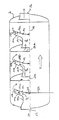
この混合装置は、筒状のハウジング2内に、軸10に沿って連続に配置された三つの放射拡散器要素4、6及び8を含む。
【0009】
放射拡散器要素4、6及び8は、それぞれ、湾曲したガイドバフル14a 、14b 及び14c 並びに湾曲した停滞バフル(stagnation baffle)16a、16b 及び16c に接続された筒状の入口末端12a 、12b 及び12cから構成され、上記停滞バフルにより、ガス流に部分的に流動の停滞が起こり、図中の矢印によって示されるようにガス流が出口末端18a 、18b 及び18c に放射状に導かれる。
【0010】
オフガス流20は、ハウジング2内の入口22を介して混合装置内に導入されそしてこれを通過して第一放射拡散器4の入口12aに向かう。
【0011】
ガス流の放射状拡散の前に、このガス流は、管24から導入される反応体ガスと混合される。
【0012】
反応体ガス24は、停滞バフル14a 上に中央に配置されたノズル26を介してガス流20に導入される。次いでこの混合ガス流は、ガイドバフル14a と停滞バフル16a の間のコンダクト28を放射状に通過して出口末端18a に導かれる。更にこの混合ガス流は、順次、拡散器要素6及び8に導入される。拡散器要素6及び8には、それぞれ、拡散器4及び6を通過したガス流を集めるための、入口12b 及び12c に接続されたガス収集器30a 及び30b が装備されている。上記の混合装置を通過することによって、反応体ガスはオフガス流と十分に混合されそして混合装置の出口末端32の所で均一なガス流として排出される。
【0013】
図2は本発明の第二の態様を示すものである。ここでは、この混合装置は、反応体ガスの導入に使用されるノズル26に加えて第二のノズル流を発生させる中央転向体11をハウジング2内に含む。この転向体の前面末端の所で、ガス流の一部(15)は、環状ダクト12へ外側に放射状に流動させられる。その後、遷移流動要素13においてこのガス流は内側に転向し、そうしてこのガス流は管路またはダクト14によりハウジング2を通過し、そしてこのダクト14において再び全断面を満たすようになる。流動拡大部16において、今や実質的にまたは完全に混合された流れが、モノリス31を含むハウジング30中に進入する。
【図面の簡単な説明】
【図1】図1は、筒状のハウジング内に連続に配置された三つの放射拡散器要素を含む本発明による混合装置の一態様を示すものである。
【図2】図2は、ハウジング内に中央転向体を有する本発明による混合装置の一態様を示すものである。
【記号の説明】
2 ・・・ ハウジング
4、6、8 ・・・ 放射拡散器要素
10 ・・・ ハウジング2内の軸
11 ・・・ 中央転向体
12 ・・・ 環状ダクト
12a 、12b 、12c ・・・ 筒状入口末端
13 ・・・ 遷移流動要素
14 ・・・ ハウジング2の後のダクト
14a 、14b 、14c ・・・ ガイドバフル
15 ・・・ 環状ダクト12に外側に放射状に流動するガス流
16 ・・・ 流動拡大部
16a 、16b 、16c ・・・ 停滞バフル
18a 、18b 、18c ・・・ 出口末端
20 ・・・ 導入オフガス流
22 ・・・ 入口
24 ・・・ 反応体ガス導入管
26 ・・・ ノズル
28 ・・・ ガイドバフルと停滞バフルとの間のコンダクト
30 ・・・ モノリスを含むハウジング
30a 、30b ・・・ ガス収集器
31 ・・・ モノリス
32 ・・・ 混合装置の出口末端
Claims (4)
- ハウジング(2)内に、それの中でガス流を半径方向に転向させる少なくとも一つの転向体、及び第二ガス流を導入するための第一ノズル装置(26)を含む、第一及び第二ガス流を混合するための混合装置であって、
前記転向体が、
− 筒状の入口端部(12a、b、c)、及び
− 出口端部(18a、b、c)、並びに
− 前記入口端部(12a、b、c)と出口端部(18a、b、c)との間にガイドバフル(14a、b、c)及びこれと並置した停滞バフル(16a、b、c)
を有する放射拡散器(4、6、8)の形であり、
前記ガイドバフル(14a、b、c)と停滞バフル(16a、b、c)との間には、コンダクト(28)が画定され、このコンダクト(28)の端部にある出口が前記出口端部(18a、b、c)を形成し、前記第一のノズル装置(26)は、拡散器(4、6、8)の入口にまたは停滞バフル(16a、b、c)の軸上に配置されており、
この際、上記拡散器(4、6、8)のこれらの構成要素及び前記第一ノズル装置(26)は、次のように、すなわち前記入口端部(12a、b、c)から前記拡散器(4、6、8)中に流入した前記第一ガス流が、この拡散器(4、6、8)内で、前記第一ノズル装置(26)から導入された第二ガス流と合流し、そして停滞バフル(16a、b、c)に衝突してその流れの方向を変えて、前記コンダクト(28)中を流れてそして出口端部(18a、b、c)から排出されるように配置されている、前記混合装置。 - 前記第一ノズル装置(26)が、ハウジング(2)の軸に対し実質的に回転対称的に配置されている、請求項1の混合装置。
- ハウジング(2)がオフガス流路の一区画内に装備されている、請求項1の混合装置。
- 請求項1〜3のいずれか一つの混合装置が装備されている、オフガスの触媒作用処理のためのオフガス流路。
Applications Claiming Priority (2)
| Application Number | Priority Date | Filing Date | Title |
|---|---|---|---|
| US8492798P | 1998-05-11 | 1998-05-11 | |
| US60/084927 | 1998-05-11 |
Publications (3)
| Publication Number | Publication Date |
|---|---|
| JP2000033251A JP2000033251A (ja) | 2000-02-02 |
| JP2000033251A5 JP2000033251A5 (ja) | 2006-05-11 |
| JP4468513B2 true JP4468513B2 (ja) | 2010-05-26 |
Family
ID=22188092
Family Applications (1)
| Application Number | Title | Priority Date | Filing Date |
|---|---|---|---|
| JP12895899A Expired - Lifetime JP4468513B2 (ja) | 1998-05-11 | 1999-05-10 | 混合装置及びそれが装備された燃料ガス流路 |
Country Status (2)
| Country | Link |
|---|---|
| EP (1) | EP0960650A1 (ja) |
| JP (1) | JP4468513B2 (ja) |
Families Citing this family (2)
| Publication number | Priority date | Publication date | Assignee | Title |
|---|---|---|---|---|
| DK1979083T3 (en) * | 2005-12-23 | 2018-06-14 | Exxonmobil Res & Eng Co | MANAGED COMBUSTION FOR REGENERATIVE REACTORS WITH MIXING DEVICE / FLOW BENEFITS |
| CN109351140B (zh) * | 2018-12-05 | 2024-03-01 | 航天环境工程有限公司 | 一种热等离子体废气处理装置及应用 |
Family Cites Families (7)
| Publication number | Priority date | Publication date | Assignee | Title |
|---|---|---|---|---|
| JPS592768B2 (ja) * | 1976-02-10 | 1984-01-20 | 株式会社日立製作所 | ガスタ−ビンの排ガス処理方法及びその装置 |
| DE3014934A1 (de) * | 1980-04-18 | 1981-10-22 | Bergwerksverband Gmbh, 4300 Essen | Verfahren zur entfernung von schwefeloxiden und stickstoffoxiden aus abgasen |
| JPS60255132A (ja) * | 1984-05-30 | 1985-12-16 | Babcock Hitachi Kk | 脱硝反応装置 |
| US4960571A (en) * | 1988-12-14 | 1990-10-02 | Exxon Research And Engineering Company | Quench assembly design |
| ZA904363B (en) * | 1989-06-24 | 1991-03-27 | Degussa | Process for the regeneration of soot filters on diesel engines |
| DK169823B1 (da) * | 1993-02-01 | 1995-03-06 | Silentor As | Lyddæmper |
| WO1996036796A1 (en) * | 1995-05-19 | 1996-11-21 | Silentor A/S | A silencer with incorporated catalyst |
-
1999
- 1999-05-10 JP JP12895899A patent/JP4468513B2/ja not_active Expired - Lifetime
- 1999-05-11 EP EP99109446A patent/EP0960650A1/en not_active Withdrawn
Also Published As
| Publication number | Publication date |
|---|---|
| EP0960650A1 (en) | 1999-12-01 |
| JP2000033251A (ja) | 2000-02-02 |
Similar Documents
| Publication | Publication Date | Title |
|---|---|---|
| US6257754B1 (en) | Mixing device and flue gas channel provided therewith | |
| RU2136355C1 (ru) | Статический аппарат для смешивания различных газовых потоков | |
| EP1438491B1 (en) | Gas treatment apparatus | |
| CN101649765B (zh) | 废气系统 | |
| JPH10511038A (ja) | 燃焼設備からの排気ガスの触媒浄化方法と装置 | |
| BR122021010883B1 (pt) | Disposição de mistura | |
| US20070274877A1 (en) | Gas treatment appartatus | |
| US5185998A (en) | Catalytic converter accessory apparatus | |
| KR20150142056A (ko) | 유동 반전형 배기가스 혼합기 | |
| WO2005098211A1 (ja) | 排気浄化機能付き消音装置 | |
| EP1262644A3 (en) | Catalytic converter | |
| JP2009019610A (ja) | 排気浄化装置 | |
| CN111828140B (zh) | 混合器 | |
| KR20160107248A (ko) | 축류 분무 모듈 | |
| CN109184863B (zh) | 一种scr混合系统及其scr混合器 | |
| JP4468513B2 (ja) | 混合装置及びそれが装備された燃料ガス流路 | |
| WO2019089041A1 (en) | Flow reversing mixer assembly | |
| HU218077B (hu) | Berendezés és eljárás oxidálható részek elégetésére tisztítandó hordozógázban | |
| US20090003127A1 (en) | Method and Apparatus for Mixing a Gaseous Fluid With a Large Gas Stream, Especially for Introducing a Reducing Agent Into a Flue Gas That Contains Nitrogen Oxides | |
| CN109386355B (zh) | 混合器装置和废气系统 | |
| KR101780341B1 (ko) | 축류 분무 모듈 | |
| JP2008267225A (ja) | 排気浄化装置 | |
| CN110821612B (zh) | 排气处理装置 | |
| CN115405398A (zh) | 用于车辆排气系统的混合器组件 | |
| JPH09900A (ja) | 粉体と気体の混合装置 |
Legal Events
| Date | Code | Title | Description |
|---|---|---|---|
| A521 | Written amendment |
Free format text: JAPANESE INTERMEDIATE CODE: A523 Effective date: 20060316 |
|
| A621 | Written request for application examination |
Free format text: JAPANESE INTERMEDIATE CODE: A621 Effective date: 20060316 |
|
| A977 | Report on retrieval |
Free format text: JAPANESE INTERMEDIATE CODE: A971007 Effective date: 20080612 |
|
| A131 | Notification of reasons for refusal |
Free format text: JAPANESE INTERMEDIATE CODE: A131 Effective date: 20080708 |
|
| A601 | Written request for extension of time |
Free format text: JAPANESE INTERMEDIATE CODE: A601 Effective date: 20081007 |
|
| A602 | Written permission of extension of time |
Free format text: JAPANESE INTERMEDIATE CODE: A602 Effective date: 20081010 |
|
| A521 | Written amendment |
Free format text: JAPANESE INTERMEDIATE CODE: A523 Effective date: 20081106 |
|
| TRDD | Decision of grant or rejection written | ||
| A01 | Written decision to grant a patent or to grant a registration (utility model) |
Free format text: JAPANESE INTERMEDIATE CODE: A01 Effective date: 20100126 |
|
| A01 | Written decision to grant a patent or to grant a registration (utility model) |
Free format text: JAPANESE INTERMEDIATE CODE: A01 |
|
| A61 | First payment of annual fees (during grant procedure) |
Free format text: JAPANESE INTERMEDIATE CODE: A61 Effective date: 20100225 |
|
| R150 | Certificate of patent or registration of utility model |
Free format text: JAPANESE INTERMEDIATE CODE: R150 |
|
| FPAY | Renewal fee payment (event date is renewal date of database) |
Free format text: PAYMENT UNTIL: 20130305 Year of fee payment: 3 |