JP4468005B2 - Tire rubber layer forming method and tire manufacturing method - Google Patents
Tire rubber layer forming method and tire manufacturing method Download PDFInfo
- Publication number
- JP4468005B2 JP4468005B2 JP2004047683A JP2004047683A JP4468005B2 JP 4468005 B2 JP4468005 B2 JP 4468005B2 JP 2004047683 A JP2004047683 A JP 2004047683A JP 2004047683 A JP2004047683 A JP 2004047683A JP 4468005 B2 JP4468005 B2 JP 4468005B2
- Authority
- JP
- Japan
- Prior art keywords
- tire
- layer
- rubber
- carcass
- belt
- Prior art date
- Legal status (The legal status is an assumption and is not a legal conclusion. Google has not performed a legal analysis and makes no representation as to the accuracy of the status listed.)
- Expired - Fee Related
Links
Images


Description
本発明は、未加硫ゴムの連続体を巻き付けてタイヤのゴム層を形成するゴム層の形成方法と、その方法を利用したタイヤの製造方法に関する。 The present invention includes a method for forming the rubber layer forming a rubber layer of the tire by winding a continuous body of unvulcanized rubber, a method of manufacturing a tire using the method.
従来、空気入りタイヤは一般的に次のようにして製造されていた。まず、インナーライナやカーカス、サイドウォールなどを構成するゴム部材の断面形状に見合った口金をそれぞれ用意し、その口金を介して押出成形したゴム部材を定寸にカットして所望のゴム部材を調製する。次に、各ゴム部材をドラム外周面にセットして円筒状の成形体を作製する。その成形体にブラダーと呼ばれるゴムバッグを用いて内圧をかけ、略タイヤ寸法まで膨らませてから、ベルト部材及びトレッド部材を貼り合わせて未加硫ゴムからなる生タイヤを成形する。その後、加硫装置のモールド(外型)内に生タイヤをセットし、タイヤ内部から加圧しながら加熱・加硫させ、必要により内圧を維持したまま冷却して製品タイヤを製造する。 Conventionally, pneumatic tires are generally manufactured as follows. First, prepare bases that match the cross-sectional shape of the rubber members that make up the inner liner, carcass, sidewalls, etc., and cut the rubber members extruded through the bases to a specific size to prepare the desired rubber members To do. Next, each rubber member is set on the drum outer peripheral surface to produce a cylindrical molded body. An internal pressure is applied to the molded body using a rubber bag called a bladder to inflate it to a substantially tire size, and then a belt member and a tread member are bonded together to form a raw tire made of unvulcanized rubber. Thereafter, a raw tire is set in a mold (outer mold) of a vulcanizer, heated and vulcanized while being pressurized from the inside of the tire, and cooled while maintaining the internal pressure as necessary to produce a product tire.
しかしながら、インナーライナやサイドウォールなどを構成するゴム部材は、タイヤの構造およびサイズの多様化に伴って極めて多数の種類があるため、タイヤの品種に応じた多量の口金などを用意しなければならず、更にタイヤの品種替えの度に口金の交換や調整作業が必要とされ、多品種少量生産には不適であった。また、ゴム部材をドラム上に慎重に位置決めしてセットする作業や、円筒状の成形体を膨らませる作業を必要とし、生産性を阻害していた。更に、円筒状の成形体を膨らませる際、タイヤ赤道線付近の領域は膨張率が大きくなるため、ゴム部材の当該領域は予め厚く形成されているとともに、その膨張は空気圧によるものであるため、タイヤの均一性(ユニフォミティ)を損なう場合があった。加えて、ベルト部材は、例えば、下記特許文献1に記載の装置によりシート状物に形成されるが、そのようなシート状物の製造には、大規模なカレンダー設備や裁断設備が必要であった。
However, there are a great many types of rubber members that make up inner liners and sidewalls as the structure and size of tires diversify, so it is necessary to prepare a large amount of caps according to the type of tire. In addition, each time the tire type is changed, the base must be changed and adjusted, making it unsuitable for high-mix low-volume production. Further, the work of carefully positioning and setting the rubber member on the drum and the work of inflating the cylindrical molded body are required, which hinders productivity. Furthermore, when the cylindrical molded body is inflated, the area near the tire equator line has a high expansion rate, so the area of the rubber member is formed thick in advance, and the expansion is due to air pressure. In some cases, the uniformity (uniformity) of the tire was impaired. In addition, the belt member is formed into a sheet-like material by, for example, an apparatus described in
これに対して、カーカス層の外周にベルト層を配したタイヤケーシングを成形し、その外周面にゴムストリップを巻き付けることによってトレッド層を形成する空気入りタイヤの製造方法が下記特許文献2に開示されている。当該方法によれば、タイヤ品種ごとにトレッド部材を調製する必要が無く、多品種少量生産に適している。しかしながら、上記タイヤケーシング自体は従来の方法によって形成されるものであり、インナーライナ層やサイドウォール層などの形成に関しては上記の欠点を有している。
On the other hand, the following
一方、剛性コアにゴムストリップを巻き付けることで、ゴム製品を形成する方法が下記特許文献3に開示されている。当該文献には、出口開口部(オリフィス)を有する押出機の並進運動および揺動運動と、前記オリフィスの回転(自転)運動により、ビード部間のタイヤ外周側にわたるゴムストリップの巻き付けを可能とし、更に、剛性コアの一定の回転角度に対して、一定の半径上に一定量のゴム量を送りだすことで、所望形状のゴム製品を形成することが開示されている。しかしながら、当該技術は、一般に重量物である押出機を巻き付け動作に伴って運動させるものであるため、比較的大規模な設備が必要となる。また、ビード部周りにゴムを配置する際、剛性コアの回転に加えて、押出機の揺動および並進、オリフィスの回転(自転)という運動が必要となるため、形成動作が複雑になり制御が比較的困難になる。
そこで、本発明の目的は、形成動作が単純で制御が比較的容易であり、生産性が高くて多品種少量生産に適し、しかもタイヤの構造的な制限が少なく、ユニフォミティに優れたタイヤのゴム層の形成方法、その方法を利用したタイヤの製造方法を提供することにある。 Accordingly, an object of the present invention is a tire rubber that has a simple forming operation and is relatively easy to control, has high productivity, is suitable for high-mix low-volume production, has few structural restrictions on tires, and has excellent uniformity. It is to provide a method for forming a layer and a method for manufacturing a tire using the method.
上記目的は、下記の如き本発明により達成できる。即ち、本発明に係るゴム層の形成方法は、タイヤを構成するゴム層の形成方法であって、未加硫ゴムからなる線状または帯状の連続体を、少なくともビード部間のタイヤ外周側に架け渡されたU字状または環状の経路部を有するガイド装置を用いて、前記経路部に沿って移動可能なガイド部によりガイドしつつ、ゴム層の被形成面が設けられた環状中子を、前記ガイド装置に対してタイヤ回転方向に相対移動させて、前記連続体を前記ゴム層の被形成面上に押し付けながらタイヤ周方向に沿ってらせん状に巻き付ける工程を備える。 The above object can be achieved by the present invention as described below. That is, the method for forming a rubber layer according to the present invention is a method for forming a rubber layer constituting a tire, and a linear or belt-like continuous body made of unvulcanized rubber is disposed at least on the tire outer periphery side between bead portions. An annular core provided with a surface on which a rubber layer is formed is guided using a guide device having a U-shaped or annular path portion that is bridged and guided by a guide portion that is movable along the path portion. And a step of winding the continuum helically along the tire circumferential direction while pressing the continuum on the surface on which the rubber layer is formed, relative to the guide device in the tire rotation direction.
本発明のゴム層の形成方法によると、連続体をビード部間のタイヤ外周側に架け渡された経路部に沿ってガイドしつつ、その経路部を有するガイド装置に対して環状中子をタイヤ回転方向に相対移動させて、その連続体をゴム層の被形成面上に押し付けながら巻き付けるため、形成動作が単純で制御が容易となり、制御動作の高速化により生産性を高めることができる。また、設備の小型化が可能で取り扱いが容易となり、しかも連続体をタイヤ周方向に沿ってらせん状に巻き付けるため、上記形成動作の制御によりタイヤの品種に応じたゴム層を適宜に形成することができ、多品種少量生産に対応し、製品タイヤの構造的な制限が少ないゴム層の形成方法を提供することができる。ゴム層の厚みは、任意に制御することができ、優れたユニフォミティが得られる。ガイド装置の経路部は、少なくともビード部間のタイヤ外周側に架け渡されており、踏面部に配されるトレッド層だけでなく、タイヤサイドに配されるインナーライナ層やサイドウォール層、ビード部付近のリムストリップ層などであっても、連続体をガイドして各ゴム層を効果的に形成することができる。なお、「層」とは、タイヤ成形体において、インナーライナ部などの各部を構成する構成材を指し、「部材」とは、タイヤ成形前において各部を構成する構成材を指すものとして用いられるが、本発明に係る方法では、形成した「部材」がそのままタイヤの「層」になり得るものであるため、形成物を「層」と呼んでいる。 According to the method for forming a rubber layer of the present invention, a continuous body is guided along a path portion spanned on the tire outer periphery side between the bead portions, and the annular core is tired with respect to the guide device having the path portion. Since the continuous body is wound while pressing relative to the surface on which the rubber layer is formed, the forming operation is simple and the control is easy, and the speed of the control operation can increase the productivity. In addition, it is possible to reduce the size of the equipment and facilitate handling, and in order to wind the continuous body in a spiral shape along the circumferential direction of the tire, a rubber layer corresponding to the type of tire is appropriately formed by controlling the above forming operation. Therefore, it is possible to provide a method for forming a rubber layer that can be used for a wide variety of small-quantity production and has few structural restrictions on the product tire. The thickness of the rubber layer can be arbitrarily controlled, and excellent uniformity can be obtained. The route portion of the guide device spans at least the tire outer periphery side between the bead portions, and not only the tread layer disposed on the tread surface portion but also the inner liner layer, sidewall layer, and bead portion disposed on the tire side. Even in the vicinity of the rim strip layer or the like, each rubber layer can be effectively formed by guiding the continuum. The “layer” refers to a constituent material that constitutes each part such as an inner liner part in the tire molded body, and the “member” is used to denote a constituent material that constitutes each part before the tire molding. In the method according to the present invention, since the formed “member” can directly become a “layer” of a tire, the formed product is called a “layer”.
また、本発明に係るタイヤの製造方法は、1列又は複数列のコード材を未加硫ゴムで被覆した線状または帯状のベルト用連続体を、前記ガイド装置を用いて前記ガイド部によりガイドしつつ、略カーカス層の外面形状を呈するベルト層の被形成面が設けられた環状中子を、前記ガイド装置に対してタイヤ回転方向に相対移動させて、前記ベルト用連続体を前記ベルト層の被形成面上に押し付けながらタイヤ周方向に対して所定角度に傾斜して巻き付ける工程と、前記巻き付け以前にまたは前記巻き付け以降に、前記ベルト用連続体を所定の長さに切断する工程と、を備えるベルト層の形成工程と、上記のゴム層の形成工程とを備える。 In the tire manufacturing method according to the present invention, a linear or belt-like belt continuous body in which one or more rows of cord materials are coated with unvulcanized rubber is guided by the guide portion using the guide device. However, an annular core provided with a belt layer forming surface having a substantially carcass layer outer surface shape is moved relative to the guide device in the tire rotation direction, and the belt continuum is moved to the belt layer. A step of winding at a predetermined angle with respect to the circumferential direction of the tire while being pressed onto the surface to be formed, a step of cutting the belt continuous body into a predetermined length before or after the winding , A belt layer forming step, and the rubber layer forming step .
本発明のタイヤの製造方法は、その主構成が前記ゴム層の形成方法と共通するため、上述の作用効果が奏される。即ち、形成動作が単純で制御が容易となり、制御動作の高速化により生産性を高めることができる。しかも、設備の小型化が可能で取り扱いが容易となる。また、環状中子のタイヤ回転方向への相対移動との関係において、ベルト用連続体の経路部に沿ったガイドを制御することにより、そのベルト用連続体をタイヤ周方向に対して任意の角度に傾斜させて巻き付けることができる。その際、ベルト用連続体を巻き付け以前にまたは巻き付け以降に所定の長さに切断することで、続けてベルト用連続体を巻き付けることができ、上記工程を繰返してベルト用連続体を並設することで、ベルト層を好適に形成することができる。 Since the main structure of the tire manufacturing method of the present invention is the same as that of the rubber layer forming method, the above-described effects are exhibited. That is, the forming operation is simple and the control is easy, and the productivity can be increased by increasing the speed of the control operation. In addition, the equipment can be downsized and handled easily. Further, in relation to the relative movement of the annular core in the tire rotation direction, by controlling the guide along the path portion of the belt continuum, the belt continuum can be moved at any angle with respect to the tire circumferential direction. It is possible to wind it in an inclined manner. At that time, by cutting the belt continuous body to a predetermined length before winding or after winding, the belt continuous body can be continuously wound, and the belt continuous bodies are arranged in parallel by repeating the above steps. Thereby, a belt layer can be formed suitably.
タイヤの製造方法が、上記ゴム層の形成工程を備えることにより、上記の作用効果を奏するタイヤの製造方法を提供することができる。即ち、形成動作が単純で制御が容易となり、制御動作の高速化により生産性を高めることができる。しかも、多品種少量生産に適し、製品タイヤの構造的な制限が少なく、優れたユニフォミティが得られる。また、上記ゴム層の形成工程とベルト層の形成工程は類似の機構で行うことができるため、例えば、ベルト層とサイドウォール層との形成を同じ装置や連続工程により行うことが可能となり、より生産性を高めることができる。 Method of manufacturing a tire, by providing the more formation Engineering of the rubber layer, it is possible to provide a tire manufacturing method to achieve the effect of the above. That is, the forming operation is simple and the control is easy, and the productivity can be increased by increasing the speed of the control operation. In addition, it is suitable for high-mix low-volume production, and there are few structural restrictions on the product tire, and excellent uniformity can be obtained. In addition, since the rubber layer forming step and the belt layer forming step can be performed by a similar mechanism, for example, the belt layer and the sidewall layer can be formed by the same apparatus or a continuous process. Productivity can be increased.
また、本発明に係るタイヤの製造方法は、1 列又は複数列のカーカス用コード材を未加硫ゴムで被覆した線状又は帯状のカーカス用連続体を、カーカス層の被形成面が設けられた環状中子に対して、前記カーカス用コード材が略タイヤ半径方向に配置されるように、ビード部間のタイヤ外周側とタイヤ内周側とを順次経由して繰り返し巻き付けた後、ビード部間のタイヤ内周側の前記カーカス用連続体をカーカス層の折り返し部を残して切断し、次いで、前記切断前または前記切断後に配置したビード材に対して前記折り返し部をタイヤ外側に折り返すカーカス層の形成工程と、上記のゴム層の形成工程とを備える。 In the tire manufacturing method according to the present invention, a linear or belt-like continuous body of carcass in which one or a plurality of rows of carcass cord materials are coated with unvulcanized rubber is provided with a surface on which a carcass layer is formed. The bead portion is repeatedly wound around the annular core through the tire outer periphery side and the tire inner periphery side in sequence so that the carcass cord material is arranged substantially in the tire radial direction. The carcass layer is formed by cutting the carcass continuum on the inner circumferential side of the tire while leaving the folded portion of the carcass layer, and then folding the folded portion to the outside of the tire with respect to the bead material disposed before or after the cutting. comprising a step of forming, the formation Engineering degree of the rubber layer.
これにより、例えば、上述のゴム層の形成工程によりインナーライナ層を形成した後、そのインナーライナ層の外面をカーカス層の被形成面として、連続的にカーカス層を形成することができる。更に、形成したカーカス層の外面を、サイドウォール層またはベルト層の被形成面として、上述のゴム層の形成工程によりサイドウォール層を形成したり、上述のベルト層の形成工程によりベルト層を形成したりすることができる。従って、連続工程により生タイヤを形成することができ、効率的にタイヤを製造することができる。なお、上記カーカス層の形成工程によれば、形成動作が単純で制御が容易となり、制御動作の高速化により生産性を高めることができる。また、設備の小型化が可能で取り扱いが容易となる。更に、タイヤの品種に応じて巻き付け動作の変更の必要性が少なく、多品種生産に対応し易い。しかも、ビード部間のタイヤ内周側のカーカス用連続体をカーカス層の折り返し部を残して切断するため、ビード材で巻き返されるカーカス層を十分長くすることができる。 Thereby, for example, after the inner liner layer is formed by the rubber layer forming step described above, the carcass layer can be continuously formed with the outer surface of the inner liner layer as the surface on which the carcass layer is formed. Further, the outer surface of the formed carcass layer is used as a side wall layer or belt layer forming surface, and the side wall layer is formed by the above-mentioned rubber layer forming step, or the belt layer is formed by the above-described belt layer forming step. You can do it. Therefore, a raw tire can be formed by a continuous process, and the tire can be manufactured efficiently. According to the carcass layer forming step, the forming operation is simple and easy to control, and the productivity can be increased by speeding up the control operation. In addition, the equipment can be downsized and handled easily. Furthermore, there is little need to change the winding operation depending on the tire type, and it is easy to deal with multi-product production. Moreover, since the carcass continuum on the tire inner periphery side between the bead portions is cut leaving the folded portion of the carcass layer, the carcass layer wound back by the bead material can be made sufficiently long.
上記において、前記ガイド装置が有する前記経路部が環状を呈するとともに、前記カーカス層の形成工程において、前記カーカス用連続体をその経路部に沿ってガイドしつつ、前記環状中子を前記ガイド装置に対してタイヤ回転方向に相対移動させることで、前記カーカス用連続体の巻き付けを行うものが好ましい。 In the above, the path portion of the guide device has an annular shape, and in the step of forming the carcass layer, while guiding the carcass continuous body along the path portion, the annular core is connected to the guide device. On the other hand, it is preferable that the carcass continuous body is wound by being relatively moved in the tire rotating direction.
カーカス層を形成する際、カーカス用連続体を上述したガイド装置が有する経路部に沿ってガイドしながら環状中子に巻き付けるように構成することで、同じ装置を用いて連続工程により生タイヤを形成することができ、より効率的にタイヤを製造することができる。 When the carcass layer is formed, the carcass continuum is configured to be wound around the annular core while being guided along the path portion of the guide device described above, thereby forming a raw tire by a continuous process using the same device. Tires can be manufactured more efficiently.
以下、本発明の実施の形態について、図面を参照しながら説明する。 Hereinafter, embodiments of the present invention will be described with reference to the drawings.
[第1実施形態]
図1は、タイヤの子午線断面図の一例である。タイヤTは、一対のビード部1を備え、そのビード部1間にタイヤ半径方向にコード材が配列されたカーカス層7が架け渡されるように配される。カーカス層7の端部は、ビードワイヤ9において内側から外側に向けて折り返され、この折返し部に挟まれるようにビードフィラー層6が配される。ビード部1の外側にはリムストリップ層4が配されるとともに、そこから各々タイヤ径方向外側に延びるサイドウォール層3が配される。カーカス層7のすぐ外周側にはコード材が所定の角度に配列されたベルト層8が配され、更にその外周側にはトレッド層2が配される。また、カーカス層7の内周側にはインナーライナ層5が配される。第1実施形態では、インナーライナ層5を形成する方法について説明する。
[First Embodiment]
FIG. 1 is an example of a meridian cross-sectional view of a tire. The tire T includes a pair of
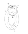
本実施形態では、インナーライナ層5は、図2〜図4に示すように、ゴムリボン11(前記連続体に相当する。)を送り出すボビン10がセットされたガイド部15を、ガイド装置17の経路部16に沿ってガイドしつつ、環状中子14をタイヤ回転方向Rに移動させて、ゴムリボン11をタイヤ周方向に順次巻き付けることで形成される。
In the present embodiment, as shown in FIGS. 2 to 4, the
ゴムリボン11は未加硫ゴムからなり、インナーライナ層5の形成に使用する未加硫ゴムであれば、カーカス層7との接着性等を考慮した材料が適宜選択される。ゴムリボン11の幅寸法は、形成するゴム層の品種によって適宜選択されるが、5〜30mmであるものが好ましく、特に5〜20mmが好ましい。ゴムリボン11の幅寸法が5mm未満であると、巻き付け回数が多くなり過ぎ、生産効率が低下するため好ましくない。一方、30mmを超えると形成精度が低下するため好ましくない。なお、インナーライナ層5を形成する場合、接合代(重なり部分)を考慮して比較的幅が広いものを使用するのが好ましい。そして、隣接するゴムリボン11同士の接合を確実にするために、例えば、断面が平行四辺形や三日月形を呈するような、傾斜した端面を有する形状が好ましい。
The
このようなゴムリボン11は、例えば、図5に示すような装置で製造することができる。この装置によれば、押出機22にて混練押し出しされた未加硫ゴムが、押出ヘッド23を介して帯状(リボン状)に押出成形される。帯状に押出されたゴムリボン11は、巻取りモータ24の駆動軸にセットされたボビン10にセパレータ13と共に巻き取られる。その際、セパレータ13はセパレータリール25から供給される。なお、セパレータ13を介在させるのは、ゴムリボン11がボビン10から好適に送り出されるようにするためであり、ゴムリボン11同士の粘着力が大きい場合に有用である。ボビン10には、1本のタイヤにおける所望のゴム層に要する量のゴムリボン11を巻いておくのが好ましいが、その量が不足する場合には、複数のボビン10を順次使用して巻き付けを行えばよい。
Such a
このように、本発明で使用するゴムリボン11は、比較的小規模な装置で製造することができ、しかも、タイヤ品種毎にゴムリボン11の形状や大きさを変化させる必要性が小さいため、多品種少量生産に対応し易くなる。
As described above, the
上記のゴムリボン11は、環状中子14に設けられるゴム層の被形成面18に巻き付けられる。ここで、環状中子14の表面は略タイヤTの内面形状を呈するものが好ましい。これにより、環状中子14の表面をインナーライナ層5の被形成面18とすることができる。また、本発明に係る方法で形成したインナーライナ層5の外周側には、後述する方法でカーカス層7やベルト層8を順次形成することができ、それらの外面をサイドウォール層3やトレッド層2などの被形成面とすることができる。つまり、本発明では、タイヤ内周側からゴム層を順次形成することが可能であるため、形成されたゴム層の外面がその外周側に配されるゴム層の被形成面となり得る。これにより、未加硫ゴムからなる生タイヤを一連の工程において製造することができる。
The
環状中子14は、不図示の駆動装置によりタイヤ回転方向Rに移動可能に構成されている。また、環状中子14は、形成後のゴム層または生タイヤの取り出しが容易なように、境界部14aにて連結と分割が自在に行えるように構成されている。境界部14aでの連結構造は、従来公知の連結手段(例えば嵌合部とロック機構の組合せ)のいずれでもよい。
The
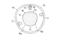
ガイド装置15は、少なくともビード部1間のタイヤ外周側TOに架け渡された経路部16と、経路部16に沿って移動可能なガイド部17とを備え、経路部16は不図示の部材により支持されている。図2および図3に示すように、本実施形態の経路部16は環状体であるとともに、その経路部16は環状中子14と互いに中空部分を貫通し合うように配置されている。ここで、経路部16は、ビード部1間のタイヤ外周側TOに架け渡されたU字状であってもよいが、本実施形態のように環状であることが好ましい。これにより、ガイド部17の移動の自由度が大きくなるとともに、後述するようなカーカス層7の形成が可能となる。なお、経路部16の形状は、円周または曲線の繋がった形状に限らず、一部に直線を含む形状でもよい。
The
ガイド装置15の経路部16は、境界部16aにて連結と分割が自在に行えるように構成されている。その部分で経路部16を分割した状態で、環状中子14の一端を挿通することにより、環状中子14の胴部周り、即ち、ゴム層の被形成面18の周りに経路部16を配置することができる。形成後のゴム層または生タイヤを取り外す際にも、同様に経路部16の分割を行えばよい。なお、境界部16aでの連結構造は、従来公知の連結手段のいずれでもよい。
The
図6に示すように、経路部16は、内周側に開口部26を有し、開口部26にセットされたガイド部17を円滑に移動させるレールの役割を果たす。経路部16の開口部26内には、全周にわたってラック27が形成されており、ガイド部17が備えるモータ29の駆動軸に設けられたピニオンギヤ28の回転によって、ガイド部17の経路部16に沿った移動が行われる。ガイド部17が備える支持ローラ30aは、経路部16に対してその内側からタイヤ径方向に当接し、更に、支持ローラ30bは経路部16に対してその内側からタイヤ周方向に当接する。これらにより、ガイド部17が経路部16に沿ってビード部1間のタイヤ外周側TOを移動する際に、ガイド部17が各方向から好適に支持される。
As shown in FIG. 6, the
図4に示すように、ガイド部17の被形成面側にはボビン支持部19が設けられ、ゴムリボン11を送り出すボビン10と、セパレータ13を巻き取るためのリール31とが、ボビン支持部19にて支持される。ボビン10は、ボビン支持部19に支持される従動軸32にセットされる。従動軸32にはゴムリボン11にかかる張力を調整するための張力調整機構を設けるのが好ましい。また、リール31と従動軸32との間には、従動軸32の回転が伝達されて、リール31による巻き取りが行えるように、適当な動力伝達機構が設けられている。
As shown in FIG. 4, a
ボビン支持部19の被形成面側には、従動軸33により軸支された押さえローラ20が設けられ、ゴムリボン11は押さえローラ20によって押さえ付けられながら被形成面18に巻き付けられる。巻き付けの際に押さえローラ20で被形成面18に押し付けることにより、タイヤサイドなどへの巻き付けであっても好適に行うことができる。
A
押さえローラ20を軸支する従動軸33は支持部材34によって支持されており、支持部材34はボビン支持部19に対してピン35によって固定されている。このピン35を緩ませると、支持部材34をピン35を中心に回動することができ、押さえローラ20と被形成面18との間隔を調整することができる。当該間隔は、形成するゴム層の厚みや位置を考慮して適宜調整することができる。
A driven
上記の装置構成によって、ガイド部17がゴムリボン11をガイドしつつ、経路部16に沿って移動することにより、ゴムリボン11をビード部1間のタイヤ外周側TOの範囲において、押し付けながらタイヤ周方向に巻き付けることができる。その際、ガイド部17の移動と環状中子14の回転とを制御することで、所望形状のゴム部材が得られる。例えば、インナーライナ層5を形成する場合は、片方のビード部1から他方のビード部1にわたってガイド部17を移動させつつ、環状中子14を回転させる。但し、ゴムリボン11をタイヤ周方向に巻き付ける際、巻き付けを開始した位置からタイヤ周方向に一回転した位置にかけて、対向する位置よりゴムリボン11の幅分だけずらした位置に巻き付けを行う必要がある。
With the above apparatus configuration, the
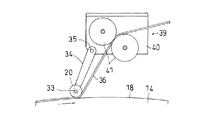
なお、ゴムリボン11を巻回したボビン10を使用せずに、押出機から押し出したゴムストリップ(前記連続体に相当する。)を、被形成面に巻き付けるものでも構わない。この場合、図7に示すように、押出機22から押し出されたゴムストリップ36はガイドローラ37を介してガイド装置38に送られる。ガイド装置38のガイド部39には、図8に示すように、上述のボビン支持部19と構成を同じくするローラ支持部40が設けられ、ローラ支持部40には従動ローラ対41が支持される。ゴムストリップ36は従動ローラ対41から、被形成面18との間隔を調整可能な押さえローラ20を介して、被形成面18に巻き付けられる。未加硫のゴムストリップ36を用いることにより、形成工程を簡略化できるとともに、良好な接着性を利用することができる。
In addition, you may wind the rubber strip (equivalent to the said continuous body) extruded from the extruder around the to-be-formed surface, without using the
また、図7および図8の装置構成において、押出機22の位置にゴムリボン11を巻回したボビンを設置し、そのボビンから送り出されたゴムリボンをガイド装置38に送って、ガイド部39によってガイドして巻き付ける構成でもよい。
7 and 8, the bobbin around which the
本発明に係るゴム層の形成方法によれば、インナーライナ層5だけでなく、サイドウォール層3やトレッド層2、ビードフィラー層6、リムストリップ層4などの他のゴム層も好適に形成することができる。この場合、ゴム層の被形成面18は、環状中子14の表面に直接設けられるものに限らず、先立って環状中子14に形成されたゴム層やカーカス層7、ベルト層8などの外面に設けられるものでもよい。
According to the rubber layer forming method of the present invention, not only the
ベルト層8やカーカス層7は、後述する方法により形成することができ、本発明によれば、生タイヤを同じ装置で連続工程により形成することができる。環状中子14は、加硫後に取り出しても構わないが、生タイヤの段階で取り外すのが好ましく、その後、加硫装置のモールド(外型)内に生タイヤをセットし、タイヤ内部から加圧しながら加熱・加硫させ、必要により内圧を維持したまま冷却して製品タイヤを製造することができる。
The
[第2実施形態]
第2実施形態では、本発明に係るタイヤの製造方法が備えうるベルト層8の形成工程について説明する。第2実施形態は、形成物がベルト層8であることと、その装置構成が以下の通りの構成である他は、第1実施形態と略同様の構成・作用であるので、相違点のみ説明し、共通の説明は省略する。
[Second Embodiment]
2nd Embodiment demonstrates the formation process of the
第2実施形態では、図9に示すように、1列又は複数列のコード材12aを未加硫ゴム12bで被覆した線状又は帯状のトッピングコード12(前記ベルト用連続体に相当する。)が使用される。コード材12aとしては、ポリエステル、レーヨン、ナイロン等の有機繊維やスチール等の金属線材が好適に使用される。未加硫ゴム12bとしては、サイドウォールゴム等の他のゴム材料との接着性等を考慮した材料が適宜選択される。トッピングコード12の幅寸法は適宜選択されるが、好ましくは5〜30mmである。
In the second embodiment, as shown in FIG. 9, a linear or belt-like topping cord 12 (corresponding to the belt continuum) in which one or more rows of
このようなトッピングコード12は、例えば、図10に示すような装置で製造することができる。図10に示す装置は、図5に示す押出機22にコード材12aを送り出す複数のリール21を付加した構成であり、平行に配列した複数のコード材12aを押出ヘッド23が未加硫ゴム12bで被覆しつつ帯状(リボン状)に押出成形する。
Such a
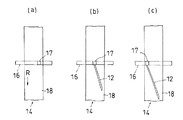
トッピングコード12の被形成面18への巻き付けは、図11(a)、(b)に示すように、環状中子14の回転量との関係におけるガイド部17の経路部16に沿った移動量を制御し、コード材12aがタイヤ周方向に対して所定の角度に傾斜するように配置する。そして、図11(c)の段階でトッピングコード12を切断する。その後、環状中子14を逆回転または1回転させて、ガイド部17を図11(a)の位置に戻す。このとき、次に巻き付けを行うトッピングコード12を、既に巻き付けたトッピングコード12に並設させるように、巻き付け開始位置をトッピングコード12の幅分だけタイヤ周方向にずらした位置とする。上記のような巻き付け動作を繰り返すことにより、タイヤ周方向にわたってベルト層8を形成することができる。
As shown in FIGS. 11A and 11B, the winding of the
トッピングコード12の切断は、例えばベルトカッターのような切断機構を設けることにより行うことができる。当該切断機構は、環状中子14の回転またはガイド部17の移動との関係において、適正なタイミングで切断を行うように制御される。切断のタイミングは、上述のように巻き付けが略終わった段階でもよいが、巻き付け開始前に予め所定の長さに切断しておくものでもよい。切断機構は、ガイド装置15に設けられるものでもよいが、押出機22から押し出しされたトッピングコード12を直接巻き付ける場合は、ガイド装置15の上流側に設けられるものでもよい。なお、切断機構は、第1実施形態において、ゴム層の形成後にも使用することができる。
The topping
また、ベルト層8の外周側に、トッピングコード12をタイヤ周方向に巻き付けることで、ベルト補強層を形成することもできる。
Further, the belt reinforcing layer can be formed by winding the
[第3実施形態]
第3実施形態では、カーカス層7を形成する方法について説明する。当該カーカス層7の形成工程は、前述のゴム層の形成工程の前工程または後工程として、若しくは前述のベルト層の形成工程の前工程として、本発明に係るタイヤの製造方法が備えるものである。
[Third Embodiment]
In the third embodiment, a method for forming the
カーカス層7の形成には、1列又は複数列のカーカス用コード材を未加硫ゴムで被覆した線状又は帯状のトッピングコード42(前記カーカス用連続体に相当する。)が使用され、例えば、図9に示す装置によって上記のトッピングコード12と同様に製造することができる。カーカス用コード材としてはポリエステル、レーヨン、ナイロン等の有機繊維やスチール等の金属線材が好適に使用される。トッピングコード42は、カーカス層7の被形成面、例えば、第1実施形態の方法により環状中子14の表面に形成されたインナーライナ層5の外面に対して、カーカス用コード材が略タイヤ半径方向に配置されるように巻き付けられる。
For the formation of the
カーカス層7は、ゴム層やベルト層の形成に使用する前述の装置と別個の装置により形成するものでもよく、または同じ装置により形成するものでもよい。別個の装置を用いる場合、例えば、特開2001−171014に開示される装置を使用することができる。一方、上述の装置構成を用いてカーカス層7を形成する場合、経路部16は前述の実施形態のように環状である必要がある。また、トッピングコード42を略タイヤ半径方向に巻き付けるため、ガイド部17が90°回動可能に構成されているものが好ましく、更に、環状中子14には、後述する巻き付けたトッピングコード42の切断が容易になるように、図12に示すような切断用溝14bが内周側中央に設けられているものが好ましい。
The
カーカス層7の形成は、まず、図12(a)に示すように、トッピングコード42をカーカス層7の被形成面(インナーライナ層5の外面)上に、カーカス用コード材が略タイヤ半径方向に配置されるように、ビード部1間のタイヤ外周側TOとタイヤ内周側TIとを順次経由して繰り返し巻き付ける。その際、ガイド部17を経路部16に沿って環状に移動させながら、環状中子14をタイヤ回転方向Rに移動させる。トッピングコード42を巻き付けた後、図12(b)に示すように、ビード材43をビード部1に配置し、ビード部1間のタイヤ内周側TIのトッピングコード42をカーカス層7の折り返し部7aを残して、環状中子14の切断用溝14bの部分で切断する。ビード材43としては、ビードフィラー層6やビードワイヤ9、またはビード周りの補強層(図示省略)などが適宜用いられる。ビードフィラー層6やビード周りの補強層などは、第1実施形態の方法を用いて形成してもよく、適当な部材を配置するものでもよい。なお、ビード材43の配置は、上記の切断前および切断後のどちらでも構わないが、切断後のカーカス層7および折り返し部7aの位置ずれ等を防止するために切断前に配置する方が好ましい。次いで、図12(c)に示すように、配置したビード材43に対して折り返し部7aをタイヤ外側に折り返すことでカーカス層7が形成される。
First, as shown in FIG. 12 (a), the
本発明に係るタイヤの製造方法は、上述のように同一の装置を用いてカーカス層7およびカーカス層7以外のゴム層やベルト層を形成する工程を備えるものが好ましい。これにより、上述の方法によりインナーライナ層5を形成した後、そのインナーライナ層5の外面をカーカス層7の被形成面として、効率的に形成することができる。更に、形成したカーカス層7の外面をサイドウォール層3やベルト層8の被形成面として、上述の方法によりサイドウォール層3やベルト層8を形成することができ、同じ装置で連続工程により生タイヤを形成することができる。
The tire manufacturing method according to the present invention preferably includes a step of forming the
[他の実施形態]
以下、本発明の他の実施の形態について説明する。
[Other Embodiments]
Hereinafter, other embodiments of the present invention will be described.
(1)前述の実施例では、環状中子14を回転駆動させる例を示したが、本発明では、環状中子14をガイド装置15に対してタイヤ回転方向Rに相対移動させればよいため、ガイド装置15をタイヤ周方向に移動させるものでもよい。
(1) In the above-described embodiment, the example in which the
(2)前述の実施形態では、ガイド装置15が単数のガイド部17を備える例を示したが、図3に点線で示すように、複数のガイド部17がガイド装置15に設けられるものでもよい。その場合、複数のガイド部17は各々が互いに干渉しないように制御される。これにより、例えば、ゴム層の種類別にガイド部17を設けることで、ゴム材料を変更する段取替えなどを省略することができる。または、踏面部やタイヤサイドにそれぞれガイド部17を設けることで、例えば、タイヤ両サイドのサイドウォール層3を同時形成することができ、生産性を高めることができる。
(2) In the above-described embodiment, an example in which the
(3)前述の実施形態では、ベルト層8を形成する際、経路部16をタイヤ子午線方向に対して略平行に配置する例を示したが、本発明では、経路部16をタイヤ子午線方向に対して傾斜させて配置してもよい。その際、傾斜させる方向はコード材12aが配置される角度に近付けるように行う。これにより、巻き付け時における環状中子14の回転量を抑制することができ、ガイド精度を向上することができる。
(3) In the above-described embodiment, when the
また、環状中子14の回転方向に関係なく、トッピングコード12の巻き付けを行うものが好ましい。これによると、図11(c)の状態において、次に巻き付けを行うトッピングコード12を、環状中子14を逆方向に回転させながら、既に巻き付けたトッピングコード12に並設させて巻き付けることができるため、ベルト層8を効率的に形成することができる。このように往復動での巻き付けを行う場合、トッピングコード12を最終的にガイドする押さえローラ20を、タイヤ周方向の両側に設ければよい。
Further, it is preferable to wind the
(4)本発明において用いられるガイド装置の経路部およびガイド部などの構成は、上記実施例で示したものに限られない。 (4) The configuration of the path portion and the guide portion of the guide device used in the present invention is not limited to that shown in the above embodiment.
1 ビード部
3 サイドウォール層
5 インナーライナ層
7 カーカス層
8 ベルト層
10 ボビン
11 ゴムリボン
12 トッピングコード
14 環状中子
15 ガイド装置
16 経路部
17 ガイド部
18 被形成面
20 押さえローラ
34 支持部材
36 ゴムストリップ
42 トッピングコード
R タイヤ回転方向
T タイヤ
TI タイヤ内周側
TO タイヤ外周側
DESCRIPTION OF
Claims (5)
未加硫ゴムからなる線状または帯状の連続体を、少なくともビード部間のタイヤ外周側に架け渡されたU字状または環状の経路部を有するガイド装置を用いて、前記経路部に沿って移動可能なガイド部によりガイドしつつ、
ゴム層の被形成面が設けられた環状中子を、前記ガイド装置に対してタイヤ回転方向に相対移動させて、
前記連続体を前記ゴム層の被形成面上に押し付けながらタイヤ周方向に沿ってらせん状に巻き付ける工程を備えるゴム層の形成方法。 A method for forming a rubber layer of a tire, comprising:
A linear or belt-like continuous body made of unvulcanized rubber is used at least along the path portion by using a guide device having a U-shaped or annular path portion spanned on the tire outer peripheral side between the bead portions. While guiding with a movable guide part ,
An annular core provided with a surface on which a rubber layer is formed is moved relative to the guide device in the tire rotation direction,
A method for forming a rubber layer, comprising a step of winding the continuous body in a spiral shape along a tire circumferential direction while pressing the continuous body on a surface on which the rubber layer is formed.
略カーカス層の外面形状を呈するベルト層の被形成面が設けられた環状中子を、前記ガイド装置に対してタイヤ回転方向に相対移動させて、
前記ベルト用連続体を前記ベルト層の被形成面上に押し付けながらタイヤ周方向に対して所定角度に傾斜して巻き付ける工程と、
前記巻き付け以前にまたは前記巻き付け以降に、前記ベルト用連続体を所定の長さに切断する工程と、を備えるベルト層の形成工程と、
請求項1記載のゴム層の形成工程とを備えるタイヤの製造方法。 While guiding a linear or belt-like belt continuum in which one or more rows of cord materials are coated with unvulcanized rubber, using the guide device,
An annular core provided with a surface on which a belt layer having a substantially carcass layer outer shape is provided is moved relative to the guide device in the tire rotation direction,
Winding the belt continuum on the forming surface of the belt layer while inclining at a predetermined angle with respect to the tire circumferential direction; and
Cutting the belt continuous body into a predetermined length before or after the winding, and forming a belt layer ,
A method for manufacturing a tire comprising the rubber layer forming step according to claim 1.
請求項1記載のゴム層の形成工程とを備えるタイヤの製造方法。 A linear or belt-like carcass continuum in which one or a plurality of rows of carcass cord materials are coated with unvulcanized rubber is applied to the annular core provided with the surface on which the carcass layer is formed. The carcass continuum on the tire inner circumference side between the bead portions after being repeatedly wound sequentially through the tire outer circumference side and the tire inner circumference side between the bead portions so that the material is arranged substantially in the tire radial direction. Cutting the carcass layer leaving the folded portion, and then forming a carcass layer that folds the folded portion back to the outside of the tire with respect to the bead material arranged before or after the cutting, and
A tire manufacturing method and a claim 1 formed Engineering degree of the rubber layer according.
Priority Applications (1)
| Application Number | Priority Date | Filing Date | Title |
|---|---|---|---|
| JP2004047683A JP4468005B2 (en) | 2004-02-24 | 2004-02-24 | Tire rubber layer forming method and tire manufacturing method |
Applications Claiming Priority (1)
| Application Number | Priority Date | Filing Date | Title |
|---|---|---|---|
| JP2004047683A JP4468005B2 (en) | 2004-02-24 | 2004-02-24 | Tire rubber layer forming method and tire manufacturing method |
Publications (2)
| Publication Number | Publication Date |
|---|---|
| JP2005238467A JP2005238467A (en) | 2005-09-08 |
| JP4468005B2 true JP4468005B2 (en) | 2010-05-26 |
Family
ID=35020732
Family Applications (1)
| Application Number | Title | Priority Date | Filing Date |
|---|---|---|---|
| JP2004047683A Expired - Fee Related JP4468005B2 (en) | 2004-02-24 | 2004-02-24 | Tire rubber layer forming method and tire manufacturing method |
Country Status (1)
| Country | Link |
|---|---|
| JP (1) | JP4468005B2 (en) |
Families Citing this family (4)
| Publication number | Priority date | Publication date | Assignee | Title |
|---|---|---|---|---|
| JP5022677B2 (en) * | 2006-11-21 | 2012-09-12 | 株式会社ブリヂストン | Tire component manufacturing apparatus |
| JP4966001B2 (en) * | 2006-12-28 | 2012-07-04 | 住友ゴム工業株式会社 | Raw tire |
| JP2013107518A (en) * | 2011-11-22 | 2013-06-06 | Sumitomo Rubber Ind Ltd | Pneumatic tire |
| JP6251084B2 (en) | 2014-03-07 | 2017-12-20 | 住友ゴム工業株式会社 | Rigid core for tire formation |
-
2004
- 2004-02-24 JP JP2004047683A patent/JP4468005B2/en not_active Expired - Fee Related
Also Published As
| Publication number | Publication date |
|---|---|
| JP2005238467A (en) | 2005-09-08 |
Similar Documents
| Publication | Publication Date | Title |
|---|---|---|
| JP4695429B2 (en) | Pneumatic tire and manufacturing method thereof | |
| KR100696901B1 (en) | Tire forming system and forming method | |
| JP4294803B2 (en) | Manufacturing method of carcass structure of automobile tire and carcass structure of automobile wheel tire | |
| JPH11268151A (en) | Manufacture of tire | |
| JPH11254906A (en) | Tire for wheel of vehicle | |
| KR19990063992A (en) | Assembly of apparatus for manufacturing vehicle green tires | |
| JP2006347003A (en) | Manufacturing method of tire and belt forming apparatus | |
| EP1570978B1 (en) | Tire manufacturing method | |
| US20140196834A1 (en) | Apparatus and method for manufacturing a green tyre | |
| EP1779998B1 (en) | Tire molding apparatus and method of using the same | |
| JPH11268504A (en) | Tire for wheel of vehicle | |
| JPWO2006048924A1 (en) | Tire molding method and molding equipment | |
| WO2004048075A1 (en) | Tire molding system, tire production system having the same, and tire producing method | |
| JP5205384B2 (en) | Raw tire manufacturing equipment | |
| JP2007223223A (en) | Stitching apparatus and tire molding apparatus | |
| JP4532552B2 (en) | Manufacturing method and apparatus for inner liner member for tire, and tire having inner liner | |
| JP4468005B2 (en) | Tire rubber layer forming method and tire manufacturing method | |
| JPWO2006137131A1 (en) | Tire molding method and rotational movement device for drum movement support base in tire molding process | |
| JP2014069563A (en) | Method and line for tire production | |
| JP2016216044A (en) | Pneumatic tire | |
| JP2019038204A (en) | Method and apparatus for manufacturing pneumatic tire | |
| JP4432536B2 (en) | Carcass layer forming method and tire manufacturing method | |
| CN102615843B (en) | Airtyred manufacture method | |
| JP3442018B2 (en) | Method for forming carcass layer and method for manufacturing tire | |
| JP2003146027A (en) | Bead core intermediate, and manufacturing method of and device for the same |
Legal Events
| Date | Code | Title | Description |
|---|---|---|---|
| A621 | Written request for application examination |
Free format text: JAPANESE INTERMEDIATE CODE: A621 Effective date: 20061213 |
|
| A977 | Report on retrieval |
Free format text: JAPANESE INTERMEDIATE CODE: A971007 Effective date: 20091124 |
|
| A131 | Notification of reasons for refusal |
Free format text: JAPANESE INTERMEDIATE CODE: A131 Effective date: 20091210 |
|
| A521 | Request for written amendment filed |
Free format text: JAPANESE INTERMEDIATE CODE: A523 Effective date: 20100204 |
|
| RD03 | Notification of appointment of power of attorney |
Free format text: JAPANESE INTERMEDIATE CODE: A7423 Effective date: 20100204 |
|
| TRDD | Decision of grant or rejection written | ||
| A01 | Written decision to grant a patent or to grant a registration (utility model) |
Free format text: JAPANESE INTERMEDIATE CODE: A01 Effective date: 20100223 |
|
| A01 | Written decision to grant a patent or to grant a registration (utility model) |
Free format text: JAPANESE INTERMEDIATE CODE: A01 |
|
| A61 | First payment of annual fees (during grant procedure) |
Free format text: JAPANESE INTERMEDIATE CODE: A61 Effective date: 20100224 |
|
| R150 | Certificate of patent or registration of utility model |
Ref document number: 4468005 Country of ref document: JP Free format text: JAPANESE INTERMEDIATE CODE: R150 Free format text: JAPANESE INTERMEDIATE CODE: R150 |
|
| FPAY | Renewal fee payment (event date is renewal date of database) |
Free format text: PAYMENT UNTIL: 20130305 Year of fee payment: 3 |
|
| FPAY | Renewal fee payment (event date is renewal date of database) |
Free format text: PAYMENT UNTIL: 20160305 Year of fee payment: 6 |
|
| R250 | Receipt of annual fees |
Free format text: JAPANESE INTERMEDIATE CODE: R250 |
|
| R250 | Receipt of annual fees |
Free format text: JAPANESE INTERMEDIATE CODE: R250 |
|
| S531 | Written request for registration of change of domicile |
Free format text: JAPANESE INTERMEDIATE CODE: R313531 |
|
| R350 | Written notification of registration of transfer |
Free format text: JAPANESE INTERMEDIATE CODE: R350 |
|
| R250 | Receipt of annual fees |
Free format text: JAPANESE INTERMEDIATE CODE: R250 |
|
| S533 | Written request for registration of change of name |
Free format text: JAPANESE INTERMEDIATE CODE: R313533 |
|
| R350 | Written notification of registration of transfer |
Free format text: JAPANESE INTERMEDIATE CODE: R350 |
|
| R250 | Receipt of annual fees |
Free format text: JAPANESE INTERMEDIATE CODE: R250 |
|
| R250 | Receipt of annual fees |
Free format text: JAPANESE INTERMEDIATE CODE: R250 |
|
| LAPS | Cancellation because of no payment of annual fees |