JP4467957B2 - Optical lens, optical head device, optical information device, computer, optical information medium player, optical information medium server - Google Patents
Optical lens, optical head device, optical information device, computer, optical information medium player, optical information medium server Download PDFInfo
- Publication number
- JP4467957B2 JP4467957B2 JP2003389677A JP2003389677A JP4467957B2 JP 4467957 B2 JP4467957 B2 JP 4467957B2 JP 2003389677 A JP2003389677 A JP 2003389677A JP 2003389677 A JP2003389677 A JP 2003389677A JP 4467957 B2 JP4467957 B2 JP 4467957B2
- Authority
- JP
- Japan
- Prior art keywords
- optical
- wavelength
- hologram
- lens
- light
- Prior art date
- Legal status (The legal status is an assumption and is not a legal conclusion. Google has not performed a legal analysis and makes no representation as to the accuracy of the status listed.)
- Expired - Lifetime
Links
- 230000003287 optical effect Effects 0.000 title claims description 392
- 230000004075 alteration Effects 0.000 claims description 90
- 239000000463 material Substances 0.000 claims description 72
- 239000000758 substrate Substances 0.000 claims description 69
- 230000008859 change Effects 0.000 claims description 53
- 230000002093 peripheral effect Effects 0.000 claims description 36
- 230000009471 action Effects 0.000 claims description 27
- 238000001514 detection method Methods 0.000 claims description 10
- 238000003384 imaging method Methods 0.000 claims 1
- 239000004973 liquid crystal related substance Substances 0.000 description 14
- 230000000694 effects Effects 0.000 description 12
- 238000012937 correction Methods 0.000 description 11
- 230000006870 function Effects 0.000 description 5
- 230000001681 protective effect Effects 0.000 description 5
- 238000006243 chemical reaction Methods 0.000 description 4
- 230000007423 decrease Effects 0.000 description 4
- 238000010586 diagram Methods 0.000 description 4
- 230000010287 polarization Effects 0.000 description 4
- 238000004364 calculation method Methods 0.000 description 3
- 239000006185 dispersion Substances 0.000 description 3
- 239000010410 layer Substances 0.000 description 3
- 238000000034 method Methods 0.000 description 3
- 230000004044 response Effects 0.000 description 3
- 230000000630 rising effect Effects 0.000 description 3
- 239000004065 semiconductor Substances 0.000 description 3
- 238000007493 shaping process Methods 0.000 description 3
- 230000003247 decreasing effect Effects 0.000 description 2
- 238000009826 distribution Methods 0.000 description 2
- 238000005516 engineering process Methods 0.000 description 2
- 238000004519 manufacturing process Methods 0.000 description 2
- 238000000926 separation method Methods 0.000 description 2
- 238000004904 shortening Methods 0.000 description 2
- 238000003860 storage Methods 0.000 description 2
- KTTCLOUATPWTNB-UHFFFAOYSA-N 2-[2-[4-(6,7-dimethoxy-3,4-dihydro-1h-isoquinolin-2-yl)butylcarbamoyl]-4-methylphenoxy]ethyl methanesulfonate Chemical compound C1C=2C=C(OC)C(OC)=CC=2CCN1CCCCNC(=O)C1=CC(C)=CC=C1OCCOS(C)(=O)=O KTTCLOUATPWTNB-UHFFFAOYSA-N 0.000 description 1
- 238000013459 approach Methods 0.000 description 1
- 230000000593 degrading effect Effects 0.000 description 1
- 238000013461 design Methods 0.000 description 1
- 230000006866 deterioration Effects 0.000 description 1
- 238000011161 development Methods 0.000 description 1
- 239000011521 glass Substances 0.000 description 1
- 239000011229 interlayer Substances 0.000 description 1
- 230000007246 mechanism Effects 0.000 description 1
- UZHSEJADLWPNLE-GRGSLBFTSA-N naloxone Chemical compound O=C([C@@H]1O2)CC[C@@]3(O)[C@H]4CC5=CC=C(O)C2=C5[C@@]13CCN4CC=C UZHSEJADLWPNLE-GRGSLBFTSA-N 0.000 description 1
- 229940065778 narcan Drugs 0.000 description 1
- 238000012545 processing Methods 0.000 description 1
Images


Description
本発明は、例えば光ディスクなどの光情報媒体上に記憶される情報の記録・再生又は消去を行う光ヘッド装置及び光情報装置、光情報装置における記録再生方法、及びこれらを応用したシステムに関する。さらに、前記光ヘッド装置に用いる対物レンズ(光学レンズ)、回折素子及び位相段差に関する。 The present invention relates to an optical head device and an optical information device for recording / reproducing or erasing information stored on an optical information medium such as an optical disc, a recording / reproducing method in the optical information device, and a system to which these are applied. Further, the present invention relates to an objective lens (optical lens), a diffraction element, and a phase step used in the optical head device.
高密度・大容量の記憶媒体として、ピット状パターンを有する光ディスクを用いる光メモリ技術は、ディジタルオーディオディスク、ビデオディスク、文書ファイルディスク、さらにはデータファイルと用途を拡張しつつ、実用化されてきている。微小に絞られた光ビームを介して、光ディスクへの情報記録再生が高い信頼性のもとに首尾よく遂行される機能は、回折限界の微小スポットを形成する集光機能、光学系の焦点制御(フォーカスサーボ)とトラッキング制御、及びピット信号(情報信号)検出に大別される。 Optical memory technology using optical disks with pit-like patterns as high-density and large-capacity storage media has been put into practical use while expanding applications with digital audio disks, video disks, document file disks, and data files. . The functions that can be successfully performed with high reliability in recording and reproducing information on an optical disc through a finely focused light beam are the focusing function that forms a diffraction-limited microspot and the focus control of the optical system. (Focus servo), tracking control, and pit signal (information signal) detection.
近年、光学系設計技術の進歩と光源である半導体レーザーの短波長化により、従来以上の高密度の記憶容量を持つ光ディスクの開発が進んでいる。高密度化のアプローチとしては、光ディスク上へ光ビームを微小に絞る集光光学系の光ディスク側開口数(NA)を大きくすることが検討されている。 In recent years, development of optical discs with higher storage capacity than conventional ones has progressed due to advances in optical system design technology and shortening of the wavelength of semiconductor lasers as light sources. As an approach for increasing the density, it has been studied to increase the numerical aperture (NA) on the optical disc side of the condensing optical system that finely focuses the light beam onto the optical disc.
その際、問題となるのが光軸の傾き(いわゆるチルト)による収差の発生量の増大である。NAを大きくすると、チルトに対して発生する収差量が大きくなる。これを防ぐためには、光ディスクの基板の厚み(基材厚)を薄くすれば良い。 At that time, the problem is an increase in the amount of aberration caused by the tilt of the optical axis (so-called tilt). Increasing the NA increases the amount of aberration that occurs with respect to tilt. In order to prevent this, the thickness (base material thickness) of the substrate of the optical disk may be reduced.
光ディスクの第1世代といえるコンパクトディスク(CD)は赤外光(波長λ3は780nm〜820nm)、とNA0.45の対物レンズを使用し、ディスクの基材厚は1.2mmである。第2世代のDVDは赤色光(波長λ2は630nm〜680nm、標準波長650nm)、とNA0.6の対物レンズを使用し、ディスクの基材厚は0.6mmである。そして、第3世代の光ディスクは青色光(波長λ1は390nm〜415nm、標準波長405nm)、とNA0.85の対物レンズを使用し、ディスクの基材厚は0.1mmである。 A compact disk (CD) that can be said to be the first generation of an optical disk uses infrared light (wavelength λ3 is 780 nm to 820 nm) and an objective lens with NA 0.45, and the base material thickness of the disk is 1.2 mm. The second-generation DVD uses red light (wavelength λ2 is 630 nm to 680 nm, standard wavelength 650 nm) and an objective lens with NA 0.6, and the base material thickness of the disk is 0.6 mm. The third generation optical disc uses blue light (wavelength λ1 is 390 nm to 415 nm, standard wavelength 405 nm) and an objective lens with NA of 0.85, and the base material thickness of the disc is 0.1 mm.
なお、本明細書中では、基板厚みとは光ディスク(または情報媒体)に光ビームの入射する面から情報記録面までの厚みを指す。 In this specification, the substrate thickness refers to the thickness from the surface on which the light beam is incident on the optical disc (or information medium) to the information recording surface.
このように、高密度光ディスクの基板の厚みは薄くされている。経済性、装置の占有スペースの観点から、上記基材厚や記録密度の異なる光ディスクを記録再生できる光情報装置が望まれる。そのためには異なる基板の厚みの光ディスク上に回折限界まで光ビームを集光することのできる集光光学系を備えた光ヘッド装置が必要である。 As described above, the thickness of the substrate of the high-density optical disk is reduced. From the viewpoint of economy and space occupied by the apparatus, an optical information apparatus capable of recording / reproducing optical disks having different substrate thicknesses and recording densities is desired. For this purpose, an optical head device equipped with a condensing optical system capable of condensing a light beam to the diffraction limit on an optical disk having a different substrate thickness is required.
また、基材の厚いディスクを記録再生する場合には、ディスク表面より奥の方にある記録面上に光ビームを集光する必要があるので、焦点距離をより長くしなければならない。 Further, when recording / reproducing a disk having a thick base material, it is necessary to focus the light beam on a recording surface at the back of the disk surface, so that the focal length must be made longer.
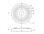
このため、異なる種類の光ディスクを複数の波長の光ビームを用いて互換再生することを目的とした構成が開示されている。これを、図20を用いて説明する。図20において10と11は透明基材厚がそれぞれ0.1mm(t1)と0.6mm(t2)の光ディスクである。剛性を強化するため、透明基材の裏面(対物レンズ40とは反対側)に保護基材を張り合わせるが、図では省略した。 For this reason, a configuration has been disclosed for the purpose of compatible reproduction of different types of optical disks using light beams of a plurality of wavelengths. This will be described with reference to FIG. In FIG. 20, 10 and 11 are optical disks having transparent substrate thicknesses of 0.1 mm (t1) and 0.6 mm (t2), respectively. In order to reinforce the rigidity, a protective substrate is bonded to the back surface of the transparent substrate (the side opposite to the objective lens 40), but this is omitted in the figure.
対物レンズ40は屈折レンズ402と屈折レンズ402の一面に異材質層401を接合したものである。屈折レンズと異材質層の屈折率と分散の違いを利用する。異なる波長の光を対物レンズにそれぞれ入射させる。光源の光束の波長が長波長側にシフトしたときに球面収差がアンダー側に変移するような球面収差特性を有する。これによって、透明基板の厚さがt1からt2のように厚くなるときに球面収差がオーバーになる分を、より波長の長い光によるアンダーによってキャンセルする。こうして厚さの異なる光ディスクの互換記録・再生を可能としている(たとえば特許文献1参照)。
The objective lens 40 is obtained by bonding a
第2の従来例としては、波長選択位相板を対物レンズと組み合わせる構成が開示されている。これを、図21と図22を用いて説明する。図21は、光ヘッド装置の概略構成を示している。波長λ1=405nmの青色光源を有する青色光光学系51より出射した平行光はビームスプリッター161及び波長選択位相板205を透過して、対物レンズ50によって、基材厚0.1mmの光ディスク9(第3世代光ディスク)の情報記録面に集光される。
As a second conventional example, a configuration in which a wavelength selection phase plate is combined with an objective lens is disclosed. This will be described with reference to FIG. 21 and FIG. FIG. 21 shows a schematic configuration of the optical head device. Parallel light emitted from the blue light
光ディスク10で反射した光は逆の経路をたどって青色光光学系51の検出器で検出される。波長λ2=650nmの赤色光源を有する赤色光光学系52より出射した発散光はビームスプリッター161で反射、波長選択位相板205を透過して、対物レンズ50によって、基材厚0.6mmの光ディスク10(第2世代光ディスク:DVD)の情報記録面に集光される。光ディスク10で反射した光は逆の経路をたどって赤色光学系52の検出器で検出される。
The light reflected by the
対物レンズ50は平行光入射時に基材厚0.1mmを透過して集光されるように設計されており、DVD記録・再生の際は基材厚の違いによって球面収差が発生する。この球面収差を補正するため、赤色光光学系52より出射して対物レンズ50にする光ビームを発散光にすると共に、波長選択位相板205を用いている。対物レンズに発散光を入射させると新たな球面収差が発生するので、基材厚の違いによって発生する球面収差をこの新たな球面収差でうち消すとともに、波長選択位相板205によっても波面を補正している。
The
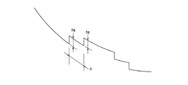
図22に波長選択位相板205の平面図である図22(a)と側面図である図22(b)を示す。波長選択位相板205は、波長λ1での屈折率をn1、h=λ1/(n1−1)として、高さh、3hの位相段差205aで構成される。波長λ1の光に対しては、高さhにより生じる光路長の差は波長λ1であり、位相差2πラジアンに相当するため、位相差0と同じである。
FIG. 22A is a plan view of the wavelength
このため、位相分布に影響を与えず、光ディスク9の記録再生には影響を与えない。一方、波長λ2の光に対しては、波長λ2での位相板205の屈折率をn2とすると、h/λ2×(n2―1)は約0.6λ、すなわち波長の整数倍ではない光路長の差を生じる。この光路長の差による位相差を利用して、先に述べた収差補正を行っている(たとえば特許文献2および、非特許文献1参照)。
For this reason, the phase distribution is not affected, and the recording / reproduction of the
また、第3の従来例としては、複数の対物レンズを機械的に切り替えて用いる構成が開示されている(たとえば特許文献3)。 As a third conventional example, a configuration in which a plurality of objective lenses are mechanically switched is disclosed (for example, Patent Document 3).
さらに、第4の従来例としては、異なる曲率半径を有する反射面を備えたミラーを光軸を折り曲げる立ち上げミラーと兼ねる構成が、特開平11−339307号公報に開示されている(たとえば特許文献4)。 Furthermore, as a fourth conventional example, Japanese Patent Laid-Open No. 11-339307 discloses a configuration in which a mirror having a reflecting surface having a different radius of curvature also serves as a rising mirror that bends the optical axis (for example, Patent Document 11). 4).
第5の従来例としては、第1の従来例と同様に屈折型の対物レンズとホログラムを組み合わせて、異なる波長の光の同じ次数の回折光に生じる色収差を利用して、基材厚の差を補正する構成が開示されている(たとえば特許文献5)。
第1の従来例は、光源の光束の波長が長波長側にシフトしたときに球面収差がアンダー側に変移するような球面収差特性を有する。これによって、透明基板の厚さがt1からt2のように厚くなるときに球面収差がオーバーになる分を、より波長の長い光によるアンダーによってキャンセルする構成である。 The first conventional example has a spherical aberration characteristic such that the spherical aberration shifts to the under side when the wavelength of the light beam of the light source is shifted to the long wavelength side. As a result, when the thickness of the transparent substrate is increased from t1 to t2, the amount by which the spherical aberration is over is canceled by the under by light having a longer wavelength.
例えば、透明基板の厚さがt1の光ディスクに対して情報再生から情報記録へと切り替える際には、光量を10倍ほど大きくする必要があり、これに伴って波長も変化し、長くなる。波長が長くなるので、球面収差がアンダーに変化するが、ディスクの厚みは変化しないので、意図しない球面収差が発生し集光性能の劣化が起こるという課題がある。 For example, when switching from information reproduction to information recording for an optical disk having a transparent substrate thickness of t1, it is necessary to increase the amount of light by about 10 times, and the wavelength changes accordingly and becomes longer. As the wavelength becomes longer, the spherical aberration changes to under, but the disc thickness does not change, so there is a problem that unintended spherical aberration occurs and the light collecting performance deteriorates.
また、光量変化による波長変化は焦点距離の変化も起こす。第1の従来例(特許文献1)の図3では、青色光の波長が10nm変化すると焦点距離が約10μm変化している。第1の従来例の図4では、赤色光の波長が10nm変化すると焦点距離が約3μm変化している。特に青色光の焦点距離変化が大きく、光量を変化させた直後、対物レンズがフォーカス制御によって移動するまでの間、集光特性が劣化するという課題がある。 In addition, a change in wavelength due to a change in the amount of light causes a change in focal length. In FIG. 3 of the first conventional example (Patent Document 1), when the wavelength of blue light changes by 10 nm, the focal length changes by about 10 μm. In FIG. 4 of the first conventional example, when the wavelength of red light changes by 10 nm, the focal length changes by about 3 μm. In particular, the focal length change of blue light is large, and there is a problem that the light collection characteristic deteriorates immediately after the light amount is changed and until the objective lens moves by focus control.
第2の従来例では、互換素子として、波長選択位相板を用いている。基材厚の厚いディスクを記録再生する際には、記録面が対物レンズに対して、基材厚の分だけ遠くなるので、焦点距離を延ばす必要がある。焦点距離は互換素子がレンズパワーを有することによって伸ばすこともできるが、波長選択位相板にはレンズパワーがない。 In the second conventional example, a wavelength selection phase plate is used as the compatible element. When recording / reproducing a disk having a thick substrate thickness, the recording surface is further away from the objective lens by the thickness of the substrate, so it is necessary to increase the focal length. The focal length can be extended by having the lens power of the compatible element, but the wavelength selective phase plate has no lens power.
また、第2の従来例のように赤色光を発散光にして、このレンズパワーをすべて実現しようとすると、トラック追従などによる対物レンズの移動時に、大きな収差が生じて記録・再生特性が劣化するという課題が生じる。 Further, if the red light is diverged as in the second conventional example to achieve all of this lens power, a large aberration occurs during the movement of the objective lens due to track following and the recording / reproduction characteristics deteriorate. The problem arises.
さらに、光ディスクで反射して対物レンズを通過して戻る光の平行度が、光ディスク基材厚によって違うので、検出レンズと光検出器を共通にすることができず、光の平行度に応じて別個に準備しなくてはならないという課題も生じる。 Furthermore, since the parallelism of the light reflected by the optical disc and returning through the objective lens differs depending on the thickness of the optical disc substrate, the detection lens and the photodetector cannot be made common, and depending on the parallelism of the light There also arises the problem that it must be prepared separately.
第3の従来例では、対物レンズを切り替えているので、複数の対物レンズを要し、部品点数が多くなると共に、光ヘッド装置の小型化が困難という課題がある。た、切り替え機構を要する点でも装置の小型化を困難にするという課題がある。 In the third conventional example, since the objective lens is switched, a plurality of objective lenses are required, the number of parts increases, and there is a problem that it is difficult to reduce the size of the optical head device. In addition, there is a problem that it is difficult to reduce the size of the apparatus in that a switching mechanism is required.
第4の従来例では、対物レンズをミラーに対して独立に駆動している(特許文献4の第4図から第6図参照)。 In the fourth conventional example, the objective lens is driven independently of the mirror (see FIGS. 4 to 6 of Patent Document 4).
ところが上述のように曲率半径をもったミラーによって光ビームを平行光から変換するので、対物レンズがトラック制御などによって移動すると、入射光波面に対する対物レンズの相対位置が変化し、収差が発生し、集光特性が劣化するという課題がある。 However, since the light beam is converted from parallel light by the mirror having the radius of curvature as described above, when the objective lens is moved by track control or the like, the relative position of the objective lens with respect to the incident light wavefront is changed, and aberration is generated. There exists a subject that a condensing characteristic deteriorates.
また、ミラーの反射面は曲率半径を持った面、すなわち球面によって構成されているが、基材厚の差と波長の差を補正するためには球面では不十分であり、5次以上の高次収差を十分に低減することができないという課題もある。 In addition, the reflecting surface of the mirror is constituted by a surface having a radius of curvature, that is, a spherical surface, but the spherical surface is insufficient to correct the difference in substrate thickness and the difference in wavelength. There is also a problem that the next aberration cannot be sufficiently reduced.
本発明は、前記のような従来の問題を解決するものであり、異なる種類の光ディスクの互換再生や互換記録を単一の対物レンズを用いて実現し、かつ光量切り替え時などの波長変化に際して、焦点距離の変化や球面収差の発生を抑制し、情報の再生又は記録の安定した光学素子、光学レンズ、及びこれらを応用した装置、システムを提供することを目的とする。さらに、単一の光ディスクを記録再生する光学素子、光学レンズ、及びこれらを応用した装置、システムも提供する。 The present invention solves the above-described conventional problems, realizes compatible reproduction and compatible recording of different types of optical discs using a single objective lens, and at the time of wavelength change such as when the light amount is switched, An object of the present invention is to provide an optical element, an optical lens, and an apparatus and a system using the same, which can suppress the change in focal length and the occurrence of spherical aberration, and can stably reproduce or record information. Furthermore, an optical element for recording / reproducing a single optical disk, an optical lens, and an apparatus and a system using these are also provided.
前記目的を達成するために、本発明の光学素子は、赤色光と青色光の少なくとも2波長に対応した光学素子であって、位相段差を備え、前記位相段差を前記青色光が透過する際に生じる光路長の差が、前記青色光の波長の5倍であることを特徴とする。 In order to achieve the object, the optical element of the present invention is an optical element corresponding to at least two wavelengths of red light and blue light, and has a phase step, and when the blue light is transmitted through the phase step. The difference in the generated optical path length is five times the wavelength of the blue light.
本発明の第1の光学レンズは、赤色光と青色光の少なくとも2波長に対応した光学レンズであって、位相段差を備え、前記位相段差を前記青色光が透過する際に生じる光路長の差が、前記青色光の波長の5倍であることを特徴とする。 First optical lens of the present invention is an optical lens which corresponds to at least two wavelengths of red light and blue light, a phase step, before Symbol the phase step of the optical path length occurring when the blue light passes through The difference is 5 times the wavelength of the blue light.
本発明の第2の光学レンズは、ホログラムと、屈折型レンズと、位相段差とを備えた光学レンズであって、前記ホログラムは、鋸歯状断面形状の鋸歯状格子を含んでおり、前記鋸歯状格子の深さの設定により、青色光に対しては+2次回折光が最も強く発生し、赤色光に対しては+1次回折光が最も強く発生し、前記位相段差を前記青色光が透過する際に生じる光路長の差が、前記青色光の波長の5倍であることを特徴とする。 The second optical lens of the present invention is an optical lens comprising a hologram, a refractive lens, and a phase step, and the hologram includes a sawtooth grating having a sawtooth cross-sectional shape, and the sawtooth shape. When the grating depth is set, + 2nd order diffracted light is generated most strongly for blue light, + 1st order diffracted light is generated most strongly for red light, and the blue light is transmitted through the phase step. The difference in the generated optical path length is five times the wavelength of the blue light.
本発明の第3の光学レンズは、ホログラムと、屈折型レンズと、位相段差とを備えた光学レンズであって、前記ホログラムは、青色光に対しては+2次回折光が最も強く発生し、赤色光に対しては+1次回折光が最も強く発生し、前記ホログラムのホログラム格子は、少なくとも前記ホログラムの光軸との交点を含む内周部に形成され、前記青色光の+2次回折光は、基材厚がt1の基材を通して集光され、前記内周部を通る前記赤色光の+1次回折光は、基材厚がt2の基材を通して集光され、t1<t2であり、前記位相段差を前記青色光が透過する際に生じる光路長の差が、前記青色光の波長の5倍であることを特徴とする。 The third optical lens of the present invention is an optical lens provided with a hologram, a refractive lens, and a phase step, and the hologram generates + 2nd order diffracted light most strongly against blue light, and red + 1st order diffracted light is most strongly generated with respect to light, the hologram grating of the hologram is formed at an inner peripheral portion including at least an intersection with the optical axis of the hologram, and the + 2nd order diffracted light of the blue light The + 1st order diffracted light of the red light that is condensed through the base material having a thickness of t1 and passes through the inner peripheral portion is condensed through the base material of the base material thickness of t2, t1 <t2, and the phase step is The difference in optical path length that occurs when blue light is transmitted is five times the wavelength of the blue light.
本発明の第1の光ヘッド装置は、前記各光学レンズと、波長λ1の青色光を出射する第1レーザー光源と、波長λ2の赤色光を出射する第2レーザー光源と、光情報媒体の記録面上で反射した光ビームを受けてその光量に応じて電気信号を出力する光検出部とを備えたことを特徴とする。 The first optical head device of the present invention includes each optical lens, a first laser light source that emits blue light having a wavelength λ1, a second laser light source that emits red light having a wavelength λ2, and recording of an optical information medium. receives the light beam reflected on the surface, characterized in that example Bei and a light detector for outputting an electrical signal according to the amount of light.
本発明の光情報装置は、前記各光学レンズのいずれかとレーザー光源とを含む光ヘッド装置と、光情報媒体を回転するモーターと、前記光ヘッド装置から得られる信号を受け前記信号に基づいて、前記モーター、前記光学レンズ、及び前記レーザー光源の少なくともいずれかを制御及び駆動する電気回路とを備えたことを特徴とする。 The optical information device of the present invention is based on the optical head device including any one of the optical lenses and a laser light source, a motor that rotates an optical information medium, and a signal obtained from the optical head device based on the signal. And an electric circuit that controls and drives at least one of the motor, the optical lens, and the laser light source.
本発明のコンピュータは、前記各光情報装置のいずれかを備え、入力された情報、及び前記光情報装置から再生された情報の少なくともいずれかに基づいて演算を行う演算装置と、前記入力された情報、前記光情報装置から再生された情報、及び前記演算装置によって演算された結果の少なくともいずれかを出力する出力装置を備えたこと特徴とする。 A computer according to the present invention includes any one of the optical information devices, an arithmetic device that performs an operation based on at least one of input information and information reproduced from the optical information device, and the input An output device is provided that outputs at least one of information, information reproduced from the optical information device, and a result calculated by the arithmetic device.
本発明の光情報媒体プレーヤーは、前記各光情報装置のいずれかと、前記光情報装置から得られる情報信号を画像に変換するデコーダーとを備えたことを特徴とする。 The optical information medium player of the present invention comprises any one of the optical information devices and a decoder that converts an information signal obtained from the optical information device into an image.
本発明のカーナビゲーションシステムは、前記各光情報装置のいずれかと、前記光情報装置から得られる情報信号を画像に変換するデコーダーとを備えたことを特徴とする。 The car navigation system according to the present invention includes any one of the optical information devices and a decoder that converts an information signal obtained from the optical information device into an image.
本発明の光情報媒体レコーダーは、前記各光情報装置のいずれかと、画像情報を前記光情報装置によって記録する情報に変換するエンコーダーとを備えたことを特徴とする。 An optical information medium recorder according to the present invention includes any one of the optical information devices and an encoder that converts image information into information recorded by the optical information device.
本発明の光情報媒体サーバーは、前記各光情報装置のいずれかと、外部との情報のやりとりを行う入出力端子とを備えたことを特徴とする。 The optical information medium server according to the present invention includes any one of the optical information devices and an input / output terminal for exchanging information with the outside.
本発明の第4の光学レンズは、1波長の光に対応した光学レンズであって、位相段差を備えており、前記位相段差を前記光が透過する際に生じる光路長の差が、前記光の波長の整数倍であることを特徴とする。 The fourth optical lens of the present invention is an optical lens corresponding to light of one wavelength, and includes a phase step, and a difference in optical path length generated when the light passes through the phase step is the light. It is characterized by being an integral multiple of the wavelength of.
本発明の第2の光ヘッド装置は、前記第4の光学レンズと、光ビームを出射するレーザー光源と、光情報媒体の記録面上で反射した光ビームを受けてその光量に応じて電気信号を出力する光検出部とを備え、前記光学レンズは、前記レーザー光源からの光ビームを基材を通して光情報媒体の記録面上へ集光することを特徴とする。 The second optical head device of the present invention receives the fourth optical lens, a laser light source that emits a light beam, and a light beam reflected on the recording surface of the optical information medium, and receives an electrical signal in accordance with the amount of light. And the optical lens condenses the light beam from the laser light source onto the recording surface of the optical information medium through the base material.
本発明は、青色光に対して波長の5倍の光路長の差を生じる位相段差によって、色収差による球面収差を補正できるので、波長の変化に対しても情報の再生や記録を安定して行うことができ、異種ディスクの互換を実現できる。 In the present invention, spherical aberration due to chromatic aberration can be corrected by a phase step that causes a difference in optical path length of 5 times the wavelength with respect to blue light, so that information can be stably reproduced and recorded even with respect to wavelength changes. And compatibility between different types of disks can be realized.
本発明の光学素子、第1の光学レンズによれば、青色光に対して波長の5倍の光路長の差を生じる位相段差によって、色収差による球面収差を補正できるので、波長の変化に対しても情報の再生や記録を安定して行うことができる。本発明において、位相段差とは光学素子に高低差を形成する段差を形成したものであり、この段差を通過する光に位相差を生じさせるものである。このことは、以下の各発明についても同様である。 According to the optical element and the first optical lens of the present invention, spherical aberration due to chromatic aberration can be corrected by a phase step that causes a difference in optical path length of 5 times the wavelength of blue light. Also, information can be reproduced and recorded stably. In the present invention, the phase step is a step in which a height difference is formed in the optical element, and a phase difference is caused in light passing through the step. The same applies to the following inventions.
本発明の第2の光学レンズによれば、青色光に対しては+2次回折光が最も強く発生し、赤色光に対しては+1次回折光が最も強く発生するようにしたことにより、焦点位置補正と基材厚差による球面収差の補正を実現できる。さらに青色光に対して波長の5倍の光路長の差を生じる位相段差によって、色収差による球面収差を補正できるので、波長の変化に対しても情報の再生や記録を安定して行うことができる。 According to the second optical lens of the present invention, the + 2nd order diffracted light is generated most strongly for blue light and the + 1st order diffracted light is generated most strongly for red light, thereby correcting the focal position. And correction of spherical aberration due to the difference in substrate thickness. Further, spherical aberration due to chromatic aberration can be corrected by a phase step that causes a difference in optical path length of 5 times the wavelength with respect to blue light, so that information can be stably reproduced and recorded even with changes in wavelength. .
本発明の第3の光学レンズによれば、ホログラムの内周部を、青色光に対しては+2次回折光が最も強く発生し、赤色光に対しては+1次回折光が最も強く発生するようにしたことにより、赤色光ビームの回折光強度を最大にでき、青色光ビームの集光スポットに対する光の利用効率も低下しないようにすることができる。さらに青色光に対して波長の5倍の光路長の差を生じる位相段差によって、色収差による球面収差を補正できるので、波長の変化に対しても情報の再生や記録を安定して行うことができる。 According to the third optical lens of the present invention, the + 2nd order diffracted light is generated most strongly for blue light and the + 1st order diffracted light is generated most strongly for red light at the inner periphery of the hologram. As a result, the diffracted light intensity of the red light beam can be maximized, and the light use efficiency with respect to the condensing spot of the blue light beam can be prevented from decreasing. Further, spherical aberration due to chromatic aberration can be corrected by a phase step that causes a difference in optical path length of 5 times the wavelength with respect to blue light, so that information can be stably reproduced and recorded even with changes in wavelength. .
本発明の第4の光学レンズによれば、色収差を補正でき、回折レンズの格子ピッチを粗くすることができ、光量の利用効率を高めることができる。 According to the fourth optical lens of the present invention, the chromatic aberration can be corrected, the grating pitch of the diffractive lens can be increased, and the light use efficiency can be increased.
本発明の第1の光ヘッド装置によれば、単一の光ヘッド装置によって、記録密度の異なる複数の光ディスクに対応することができる。 According to the first optical head device of the present invention, a single optical head device can support a plurality of optical disks having different recording densities.
本発明の第2の光ヘッド装置によれば、単一の光ディスクを記録再生する装置に用いることができる。 According to the second optical head device of the present invention, it can be used in an apparatus for recording and reproducing a single optical disk.
本発明のコンピューターや、光ディスクプレーヤー、光ディスクレコーダー、光ディスクサーバー、カーナビゲーションシステムによれば、異なる種類の光ディスクを安定に記録あるいは再生できるので、広い用途に使用できる。 According to the computer, the optical disc player, the optical disc recorder, the optical disc server, and the car navigation system of the present invention, different types of optical discs can be stably recorded or reproduced, so that it can be used for a wide range of applications.
前記第1の光学レンズにおいては、前記青色光は前記光学レンズによって基材厚がt1の基材を通して集光され、前記赤色光は基材厚がt2の基材を通して集光され、t1<t2であることが好ましい。
また、液晶型位相変調素子をさらに備えており、前記液晶型位相変調素子を電気的にスイッチングすることにより、前記青色光は前記基材厚がt1の基材を通して集光され、前記赤色光は前記基材厚がt2の基材を通して集光され、かつ透過波面に与える位相変調量を切り替えて、基材厚差による収差を補正することが好ましい。この構成によれば、ホログラムを用いることなく、液晶型位相変調素子によって、基材厚差による収差を補正することができる。
また、ホログラムをさらに備えており、前記ホログラムの回折格子の深さの設定により、青色光に対しては+2次回折光が最も強く発生し、赤色光に対しては+1次回折光が最も強く発生するようにして、基材厚差による収差を補正することが好ましい。
In the first optical lens, the blue light is condensed by the optical lens through a substrate having a substrate thickness of t1, and the red light is condensed through a substrate having a substrate thickness of t2, and t1 <t2 It is preferable that
In addition, the liquid crystal phase modulation element is further provided, and by electrically switching the liquid crystal type phase modulation element, the blue light is condensed through the base material having the thickness t1, and the red light is It is preferable that the aberration due to the difference in thickness of the substrate is corrected by switching the phase modulation amount which is condensed through the substrate having the substrate thickness t2 and applied to the transmitted wavefront. According to this configuration, it is possible to correct the aberration due to the substrate thickness difference by using the liquid crystal type phase modulation element without using a hologram.
Further, a hologram is further provided, and by setting the diffraction grating depth of the hologram, + 2nd order diffracted light is generated most strongly for blue light, and + 1st order diffracted light is generated most strongly for red light. Thus, it is preferable to correct the aberration due to the difference in substrate thickness.
また、前記光学レンズは、2種類の異なる材質で形成された屈折型レンズであることが好ましい。この構成によれば、屈折型レンズに色収差補正作用があり、この補正作用は回折による光量損失がなく、高い光利用効率と色収差補正とを両立できる。 The optical lens is preferably a refractive lens formed of two different materials. According to this configuration, the refractive lens has a chromatic aberration correcting action, and this correcting action has no light loss due to diffraction, and can achieve both high light utilization efficiency and chromatic aberration correction.
前記第2の光学レンズにおいては、前記鋸歯状格子の深さがh1であり、前記h1は、前記青色光に対して約2波長の光路長の差を与える深さであることが好ましい。この構成によれば、青色光に対して+2次回折光強度が最大となり、赤色光に対して+1次回折光強度が最大となる。 In the second optical lens, it is preferable that a depth of the sawtooth grating is h1, and the h1 is a depth that gives an optical path length difference of about two wavelengths to the blue light. According to this configuration, the intensity of the + 2nd order diffracted light is maximized for the blue light, and the intensity of the + 1st order diffracted light is maximized for the red light.
また、前記ホログラムのうち、前記ホログラムの光軸との交点を含む内周部に形成された前記鋸歯状格子の深さはh2であり、前記h2は、前記赤色光に対して約1波長の光路長の差を与える深さであることが好ましい。この構成によれば、赤色光ビームの回折光強度を最大にでき、青色光ビームの集光スポットに対する光の利用効率も低下しないようにすることができる。 The depth of the sawtooth grating formed on the inner periphery including the intersection with the optical axis of the hologram is h2, and the h2 is about one wavelength with respect to the red light. It is preferable that the depth gives a difference in optical path length. According to this configuration, the diffracted light intensity of the red light beam can be maximized, and the light use efficiency with respect to the condensing spot of the blue light beam can be prevented from decreasing.
前記第3の光学レンズにおいては、前記内周部の外側の外周部に、さらにホログラム格子が形成されており、前記外周部の前記ホログラム格子は鋸歯状断面形状の鋸歯状格子であり、前記外周部の鋸歯状格子の深さはh3であり、前記h3は、前記青色光に対して約1波長の光路長の差を与える深さであり、前記外周部においては、前記青色光に対して+1次回折光が最も強く発生し、赤色光に対しても+1次回折光が最も強く発生することが好ましい。この構成によれば、薄型の光ディスクを青色光ビームによって記録・再生するときの開口数NAbを、DVD等を赤色光ビームによって記録・再生するときの開口数NArよりも大きく(NAb>NAr)することができる。 In the third optical lens, a hologram grating is further formed on the outer peripheral portion outside the inner peripheral portion, and the hologram grating in the outer peripheral portion is a sawtooth-shaped grating having a sawtooth cross-sectional shape, The depth of the sawtooth grating of the portion is h3, and h3 is a depth that gives a difference in optical path length of about one wavelength to the blue light, and at the outer peripheral portion, the depth of the blue light is It is preferable that the + 1st order diffracted light is generated most strongly and the + 1st order diffracted light is generated most strongly with respect to red light. According to this configuration, the numerical aperture NAb when a thin optical disk is recorded / reproduced with a blue light beam is larger than the numerical aperture NAr when a DVD or the like is recorded / reproduced with a red light beam (NAb> NAr). be able to.
また、前記各光学レンズにおいては、前記青色光は、基材厚t1の基材を通して集光し、前記青色光の波長λ1が変化したときの焦点距離変化を低減させるように、前記ホログラムを凸レンズ型にして、前記青色光が前記ホログラムにより凸レンズ作用を受けるようにしていることが好ましい。 In each of the optical lenses, the blue light is condensed through a base material having a base material thickness t1, and the hologram is a convex lens so as to reduce a change in focal length when the wavelength λ1 of the blue light changes. Preferably, the blue light is subjected to a convex lens action by the hologram.
また、前記青色光は前記光学レンズによって基材厚がt1の基材を通して集光され、前記赤色光は基材厚がt2の基材を通して集光され、t1<t2であり、前記青色光が前記基材厚t1の基材を通して集光するときは、前記赤色光が前記基材厚t2の基材を通して集光するときに比べて、前記ホログラムによる凸レンズ作用を大きくして、前記赤色光の前記基材側の焦点位置を、前記青色光の前記基材側の焦点位置に比べて、前記光学レンズより離していることが好ましい。 In addition, the blue light is condensed through the base material having the base material thickness t1 by the optical lens, the red light is condensed through the base material having the base material thickness t2, and t1 <t2, and the blue light is When condensing through the base material with the base material thickness t1, the convex lens action by the hologram is increased compared to when the red light is condensed through the base material with the base material thickness t2, and the red light The focal position on the substrate side is preferably separated from the optical lens as compared to the focal position on the substrate side of the blue light.
また、前記青色光は前記光学レンズによって基材厚がt1の基材を通して集光され、前記赤色光は基材厚がt2の基材を通して集光され、t1<t2であり、前記赤色光が前記基材厚t2の基材を通して集光するときは、前記青色光が前記基材厚t1の基材を通して集光するときに比べて、前記ホログラムによる凸レンズ作用を小さくして、前記赤色光の前記基材側の焦点位置を、前記青色光の前記基材側の焦点位置に比べて、前記光学レンズより離していることが好ましい。 In addition, the blue light is collected through the base material having the base material thickness t1 by the optical lens, the red light is condensed through the base material having the base material thickness t2, and t1 <t2, and the red light is When condensing through the base material with the base material thickness t2, the convex lens action by the hologram is made smaller than when the blue light is condensed through the base material with the base material thickness t1, and the red light The focal position on the substrate side is preferably separated from the optical lens as compared to the focal position on the substrate side of the blue light.
また、前記ホログラムの格子断面形状は、前記ホログラムを形成する基材の外周側に斜面を持つ鋸歯形状であることが好ましい。 Moreover, it is preferable that the grating | lattice cross-sectional shape of the said hologram is a sawtooth shape which has a slope on the outer peripheral side of the base material which forms the said hologram.
また、前記ホログラム、前記屈折型レンズ、及び前記位相段差を一体固定していることが好ましい。また、前記ホログラムを前記屈折型レンズ表面に一体形成していることが好ましい。また、前記位相段差を前記屈折型レンズの表面に一体形成していることが好ましい。これらの構成によれば、焦点制御やトラッキング制御に際しては、共通の駆動手段によって一体に駆動を行い、ホログラムと対物レンズの相対位置のずれによる収差増大を防ぐことができる。 Moreover, it is preferable that the hologram, the refractive lens, and the phase step are integrally fixed. Moreover, it is preferable that the hologram is integrally formed on the surface of the refractive lens. Further, it is preferable that the phase step is integrally formed on the surface of the refractive lens. According to these configurations, when focus control and tracking control are performed, driving is performed integrally by a common driving unit, and an increase in aberration due to a shift in the relative position between the hologram and the objective lens can be prevented.
また、波長の変化によって、屈折型レンズ又は屈折型レンズとホログラムとに生じる収差を、前記位相段差に生じる収差によって減じることが好ましい。 In addition, it is preferable that the aberration generated in the refractive lens or the refractive lens and the hologram due to the change in wavelength is reduced by the aberration generated in the phase step.
また、青色光が基材厚がt1の基材を通して集光される開口数をNAb、赤色光が基材厚がt2の基材を通して集光される開口数をNArとすると、t1<t2、かつ、NAb>NArであることが好ましい。 Further, if NAb is the numerical aperture at which the blue light is collected through the base material having the base material thickness t1, and NAr is the numerical aperture at which the red light is collected through the base material having the base material thickness t2, then t1 <t2. And it is preferable that NAb> NAr.
前記光ヘッド装置においては、前記光学レンズは、前記第1レーザー光源からの第1光ビームを基材厚t1の基材を通して第1光情報媒体の記録面上へ集光し、前記第2レーザー光源からの第2光ビームを基材厚t2の基材を通して第2光情報媒体の記録面上へ集光し、t1<t2であることが好ましい。
また、前記第2光ビームを前記第2光情報媒体の記録面上へ集光する際に、前記第2光ビームを略平行光にするコリメートレンズを前記第2レーザー側に近づけて、拡散光にした前記第2光ビームを前記光学レンズに入射させて、前記第2光情報媒体側の焦点位置を前記光学レンズから離すことが好ましい。
In the optical head device, the optical lens focuses the first light beam from the first laser light source on the recording surface of the first optical information medium through the substrate having a substrate thickness t1, and the second laser. The second light beam from the light source is condensed on the recording surface of the second optical information medium through the substrate having the substrate thickness t2, and it is preferable that t1 <t2.
Further, when condensing the second light beam onto the recording surface of the second optical information medium, a collimating lens that makes the second light beam substantially parallel light is brought close to the second laser side to diffuse light. It is preferable that the second light beam is incident on the optical lens and the focal position on the second optical information medium side is separated from the optical lens.
また、前記第1レーザー及び前記第2レーザーの発光点の両方を、前記光学レンズの光情報媒体側の焦点位置に対して結像関係にあるように配置することによって、共通の光検出器からサーボ信号を検出することが好ましい。 Further, by arranging both the emission points of the first laser and the second laser so as to form an image with respect to the focal position on the optical information medium side of the optical lens, a common photodetector can be used. It is preferable to detect a servo signal.
前記光情報装置においては、前記レーザー光源は、波長λ1の青色光を出射する第1レーザー光源と、波長λ2の赤色光を出射する第2レーザー光源とであり、前記光情報媒体の種類を判別して、基材厚が約0.6mmの光情報媒体に対してはコリメートレンズを第2レーザー光源側に移動することが好ましい。 In the optical information device, the laser light source is a first laser light source that emits blue light with a wavelength λ1 and a second laser light source that emits red light with a wavelength λ2, and determines the type of the optical information medium Thus, it is preferable to move the collimating lens toward the second laser light source for an optical information medium having a substrate thickness of about 0.6 mm.
以下、本発明の一実施の形態について図面を参照しながら説明する。 Hereinafter, an embodiment of the present invention will be described with reference to the drawings.
(実施の形態1)
図1は本発明の実施の形態1における光ヘッド装置を示す構成図である。図1において1は波長λ1(390nm〜415nm:標準的には405nm程度なので、390nm〜415nmの波長を総称して約405nmと呼ぶ)の青色レーザー光を出射する青色レーザー光源である。
(Embodiment 1)
FIG. 1 is a block diagram showing an optical head device according to Embodiment 1 of the present invention. In FIG. 1, reference numeral 1 denotes a blue laser light source that emits blue laser light having a wavelength λ1 (390 nm to 415 nm, which is generally about 405 nm, so that the wavelengths of 390 nm to 415 nm are collectively referred to as about 405 nm).
20は波長λ2(630nm〜680nm:標準的には660nmを使われることが多いので、630nm〜680nm波長を総称して約660nmと呼ぶ)の赤色レーザー光を出射する赤色レーザー光源である。
9は基材厚みt1が約0.1mm(以下0.06mm−0.11mmの基材厚を約0.1mmと呼ぶ)又はより薄い基材厚みで、波長λ1の光ビームによって記録・再生をされる光情報媒体に対応する第3世代の光ディスクである。10は基材厚みt2が約0.6mm(0.54mm〜0.65mmの基材厚を約0.6mmと呼ぶ)で、波長λ2の光ビームによって記録・再生をされる光情報媒体に対応するDVD等の第2世代の光ディスクである。 9 is a substrate thickness t1 of about 0.1 mm (hereinafter referred to as a substrate thickness of 0.06 mm-0.11 mm is referred to as about 0.1 mm) or a thinner substrate thickness, and recording / reproduction is performed with a light beam having a wavelength λ1. This is a third generation optical disc corresponding to the optical information medium to be used. 10 is an optical information medium having a substrate thickness t2 of about 0.6 mm (a substrate thickness of 0.54 mm to 0.65 mm is called about 0.6 mm) and is recorded / reproduced by a light beam with a wavelength of λ2. It is a second generation optical disc such as a DVD.
光ディスク9、10は、光の入射面から記録面までの基材のみを図示している。実際には、機械的強度を補強し、また、外形をCDと同じ1.2mmにするため、保護板と張り合わせている。光ディスク10は、厚み0.6mmの保護材と張り合わせる。光ディスク9は厚み1.1mmの保護材と張り合わせる。本発明の図面では、簡単のため、保護材は省略する。
The
青色レーザー光源1、赤色レーザー光源20は、好ましくは半導体レーザー光源とすることにより光ヘッド装置、及びこれを用いた光情報装置を小型、軽量、低消費電力にすることができる。
The blue laser light source 1 and the red laser
最も記録密度の高い光ディスク9の記録再生を行う際には、青色レーザー光源1から出射した波長λ1の青色光ビーム61がビームスプリッター4によって反射され、1/4波長板5によって円偏光になる。1/4波長板5は波長λ1、波長λ2の両方に対して、1/4波長板として作用するように設計する。
When recording / reproducing the
コリメートレンズ8によって略平行光にされ、さらに立ち上げミラー12によって光軸を折り曲げられ、ホログラム(回折型の光学素子)13と屈折型の対物レンズ14によって光ディスク9の厚さ約0.1mmの基材を通して情報記録面に集光される。
The collimating lens 8 makes the light substantially parallel, and the optical axis is bent by the rising
光ディスク9の情報記録面で反射した青色光ビーム61は、もとの光路を逆にたどって(復路)、1/4波長板5によって初期とは直角方向の直線偏光になり、ビームスプリッター4をほぼ全透過し、ビームスプリッター16で全反射され、検出ホログラム31によって回折され、さらに検出レンズ32によって焦点距離を伸ばされて、光検出器33に入射する。
The
光検出器33の出力を演算することによって、焦点制御やトラッキング制御に用いるサーボ信号及び、情報信号を得る。上記のようにビームスプリッター4は、波長λ1の光ビームに関しては、1方向の直線偏光を全反射し、それと直角方向の直線偏光を全透過する偏光分離膜である。また、後で述べるように、波長λ2の光ビームに関しては赤色レーザー20から出射する赤色光ビーム62を全透過する。このようにビームスプリッター4は偏光特性と共に波長選択性を持った光路分岐素子である。
By calculating the output of the
次に、光ディスク10の記録又は再生を行う際には、赤色レーザー光源20から出射した略直線偏光で波長λ2の光ビームがビームスプリッター16とビームスプリッター4を透過し、コリメートレンズ8によって略平行光にされ、さらに立ち上げミラー12によって光軸を折り曲げられ、ホログラム13と対物レンズ14によって光ディスク10の厚さ約0.6mmの基材を通して情報記録面に集光される。
Next, when recording or reproducing the
光ディスク10の情報記録面で反射した光ビームはもとの光路を逆にたどって(復路)、ビームスプリッター4をほぼ全透過し、ビームスプリッター16で全反射され、検出ホログラム31によって回折され、さらに検出レンズ32によって焦点距離を伸ばされて、光検出器33に入射する。
The light beam reflected by the information recording surface of the
光検出器33の出力を演算することによって、焦点制御やトラッキング制御に用いるサーボ信号及び、情報信号を得る。このように共通の光検出器33から、光ディスク9と10のサーボ信号を得るためには、青色レーザー1と赤色レーザー20の発光点を、対物レンズ14側の共通の位置に対して結像関係にあるように配置する。こうすることにより、検出器の数も配線数も減らすことができる。
By calculating the output of the
ビームスプリッター16は波長λ2に対して、1方向の直線偏光を全透過し、それと直角方向の直線偏光を全反射する偏光分離膜である。かつ、波長λ1の光ビームに関しては青色光ビーム61を全反射する。このようにビームスプリッター16も偏光特性と共に波長選択性を持った光路分岐素子である。
The
次に、図2と図3と図4を用いてホログラム134および対物レンズ144の働きと構成を説明する。図2において134はホログラムである。ホログラム134は、波長λ1の青色光ビーム61を回折して、凸レンズ作用を及ぼし、波長λ2の光に対しては後に説明するように回折して青色光ビームよりも弱い凸レンズ作用を及ぼす。
Next, functions and configurations of the
ここで、凸レンズ作用を及ぼす最も低次の回折を+1次回折と定義する。+1次回折から次数が増えるにつれて、回折角度も大きくなる。本実施の形態では、青色光ビームに対しては、+2次の回折が最も強く起こるように設計する。このとき、赤色光ビームは+1次回折が最も強く起こる。この場合、赤色光ビームの方が青色光ビームよりも波長が長いにもかかわらず、ホログラム134上の各点における回折角度は小さくなる。
Here, the lowest-order diffraction having a convex lens action is defined as + 1st-order diffraction. As the order increases from the + 1st order diffraction, the diffraction angle also increases. In the present embodiment, the blue light beam is designed so that + 2nd-order diffraction occurs most strongly. At this time, the red light beam has the strongest + 1st order diffraction. In this case, although the wavelength of the red light beam is longer than that of the blue light beam, the diffraction angle at each point on the
すなわち、ホログラム134が、波長λ1の青色光ビーム61を回折するときの凸レンズ作用の方が、波長λ2の光に対して及ぼす凸レンズ作用よりも強くなる。言い換えると、赤色光ビームはホログラム134によって凸レンズ作用を受けるものの、青色光ビームの受ける作用を基準にすると、相対的には回折によって、凹レンズ作用を受ける。
That is, the convex lens action when the
対物レンズ144は、波長λ1の青色光ビームがホログラム134によって+2次回折されて凸レンズ作用を受けた後に、さらに集光されて光ディスク9の基材厚t1を通して記録面上へ集光するように設計される。
The
次に、赤色光ビームを用いて光ディスク10の記録・再生を行う際のホログラム134の働きを詳細に説明する。ホログラム134は波長λ2の光(点線:赤色光ビーム62)を+1次回折して、凸レンズ作用を及ぼす。そして、対物レンズ144によって赤色光ビーム62を光ディスク10の厚さt2が約0.6mmの基材を通して情報記録面101に集光する。
Next, the function of the
ここで、ディスク10はその光入射面から情報記録面101までの基材厚が0.6mmと、厚くなっており、基材厚0.1mmの光ディスク9を記録再生する場合の焦点位置よりも焦点位置を対物レンズ144から離す必要がある。図2に示すように波面変換によって、青色光ビーム61を集光光にし、赤色光ビーム62の集光度を青色光ビームの集光度よりも緩くすることにより、この焦点位置補正と基材厚差による球面収差の補正を実現する。波長λ1の青色光ビーム61と波長λ2の赤色光ビーム62は、いずれもホログラム134によって波面の変換をされる。
Here, the thickness of the base material from the light incident surface to the
したがって、ホログラム134と対物レンズ144の相対位置に誤差があると、設計どおりの波面が対物レンズ144に入射せず、光ディスク9や、光ディスク10へ入射する波面に収差が生じ、集光特性が劣化する。そこで、望ましくは、ホログラム134と対物レンズ144を一体に固定し、焦点制御やトラッキング制御に際しては、共通の駆動手段15(図1)によって一体に駆動を行う。
Therefore, if there is an error in the relative position between the
図3はホログラム134を示す。図3(a)は平面図、図3(b)は図2と同様の断面図であり、平面図とは直角の方向から見た図である。ホログラム134は、内外周境界134Aの内側(内周部134C)と外側(内外周境界134Aと有効範囲134Dの間の外周部134B)が、異なるものである。
FIG. 3 shows the
内周部134Cは、ホログラム134と光軸との交点、すなわち中心を含む領域である。この領域は、赤色光ビームを用いて光ディスク10の、記録・再生を行う際も、青色光ビームを用いて光ディスク9の、記録・再生を行う際も使用する。
The inner peripheral portion 134C is an area including the intersection, that is, the center between the
したがって、内周部134Cの回折格子と、ここから回折される赤色光ビームが通過する対物レンズ144の部分は、青色光ビームの+2次回折光が光ディスク9に、赤色光ビームの+1次回折光が光ディスク10に集光されるように設計する。外周部134Bについては、光ディスク9を青色光ビーム61によって記録・再生するときの開口数NAbが光ディスク10を赤色光ビーム62によって記録・再生するときの開口数NArよりも大きい(NAb>NAr)必要がある。
Therefore, in the diffraction grating of the inner peripheral portion 134C and the portion of the
このため、赤色光ビーム62、青色光ビーム61をそれぞれ対応する光ディスク9と10に対して集光する内周部の周囲に、青色光ビーム61の例えば+2次回折光のみを光ディスク9に対して集光し、赤色光ビーム62の+1次回折光は光ディスク10に対して収差を持つように外周部134Bおよび、これに対応する対物レンズ144の外周部を設ける必要がある。
Therefore, for example, only the + 2nd order diffracted light of the
すなわち、図示しないが、対物レンズ144もホログラム134と同様に、内外周によって、異なる設計をすることが望ましい。これによって、最適なNAすなわち、NAb>NArを実現できる。
That is, although not shown, it is desirable that the
図4は、ホログラム132のホログラム格子の一周期(p4)の間の断面を説明する図である。図4(a)は、物理的な形状を示している。このような鋸の歯のような形状を鋸歯状と呼ぶ。また、斜面の方向を表すため、図4(a)の形状を、基材が左側に斜面を持つ形状と表現する。 FIG. 4 is a diagram for explaining a cross section during one period (p 4) of the hologram grating of the hologram 132. FIG. 4A shows a physical shape. Such a sawtooth-like shape is called a sawtooth shape. Moreover, in order to represent the direction of a slope, the shape of Fig.4 (a) is expressed as a shape where a base material has a slope on the left side.
この呼び方に従い、図3のホログラム134の断面形状を、基材が外周側に斜面を持つ鋸歯形状と表現する。図4(b)は、青色光に対する位相変調量を示している。図4(c)は、赤色光に対する位相変調量を示している。
In accordance with this designation, the cross-sectional shape of the
図4(a)において縦方向は鋸歯状格子の深さを示している。ホログラム材料を、例えばBK7とすると、青色光ビームに対するホログラム材料の屈折率nbは、nb=1.5302である。 In FIG. 4A, the vertical direction indicates the depth of the sawtooth lattice. If the hologram material is, for example, BK7, the refractive index nb of the hologram material with respect to the blue light beam is nb = 1.5302.
鋸歯状格子の深さは、青色光ビーム61に対して光路長の差が約2波長、すなわち位相差が約4πラジアンになる量にする。ここで、光路長の差とは、段差の有無によって生じる光路長(光学距離ともいう。媒質の長さと屈折率をかけた値)の差異を意味する。
The depth of the sawtooth grating is set so that the optical path length difference is about two wavelengths with respect to the
したがって、光路長の差Lは、段差の深さh1と、媒質と空気との屈折率の差(nb−1)との積で表わされ、下記のようになる。 Therefore, the optical path length difference L is expressed by the product of the step height h1 and the refractive index difference (nb-1) between the medium and air, and is as follows.
L=h1×(nb-1)
光路長の差が2波長の場合、L=2×λ1となり、深さh1は、下記式で表わされ、λ1=405nm、nb=1.5302を代入して、h1の値が求まる。
L = h1 × (nb-1)
When the difference in optical path length is two wavelengths, L = 2 × λ1, and the depth h1 is expressed by the following formula. Substituting λ1 = 405 nm and nb = 1.5302, the value of h1 is obtained.
h1=2×λ1/(nb-1)=1.53μm
この形状による青色光に対する位相変調量は、格子一周期の中で4π(=2π×2)ラジアン変化するため、+2次回折光強度が最大となり、スカラー計算上は100%の回折効率となる。
h1 = 2 × λ1 / (nb-1) = 1.53 μm
The amount of phase modulation for blue light with this shape changes by 4π (= 2π × 2) radians in one period of the grating, so that the intensity of the + 2nd order diffracted light is maximized and the diffraction efficiency is 100% in scalar calculation.
一方、赤色光ビーム62に対するホログラム材料の屈折率をnrとすると、ホログラム材料がBK7の場合は、nr=1.5142となる。段差h1による赤色光ビームに発生する光路長差は、h1×(nr-1)で表わされる。したがって、赤色光ビームの波長λ2に対する光路長差の倍数は、λ2=660nm、nr=1.5142を代入して下記のようになる。
On the other hand, when the refractive index of the hologram material with respect to the
h1×(nr-1)/λ2=1.19
すなわち、光路長差は波長λ2の約1.2倍となり、位相変調量は約2.4πラジアン(1.2×2π)となる。したがって、+1次回折光強度が最も強くなり計算上の回折効率は約80%となる。
h1 × (nr−1) /λ2=1.19
That is, the optical path length difference is about 1.2 times the wavelength λ2, and the phase modulation amount is about 2.4π radians (1.2 × 2π). Therefore, the + 1st order diffracted light intensity is the strongest and the calculated diffraction efficiency is about 80%.
このため、図4(a)のように、格子一周期の形状を、深さh1の鋸歯状の断面形状にすると、青色光ビーム61は、先に説明したように+2次回折が最も強いので、回折角度を決める格子周期は、実質p4/2であり、位相変化は図4(b)と同等となる。そして、赤色光ビーム62に対しては、+1次回折が最も強いので、回折角度を決める格子周期は、実質p4である。
Therefore, as shown in FIG. 4A, when the shape of one grating period is a sawtooth cross-sectional shape having a depth h1, the
前記の構成により、基材厚差の補正による異種ディスクの互換ができ、405nmや、660nmといった基準波長付近(数nm以内)での波長変化に対する色収差とりわけ焦点距離の波長依存性を相殺し低減できるという効果を得ることができる。しかしなお、波長の差によって、球面収差を変化させているのであるから、基準波長付近(数nm以内)での波長変化に対する色収差のうち球面収差変化は発生する。この球面収差変化を補正するための構成を図5と図6を用いて説明する。 With the above configuration, different types of discs can be interchanged by correcting the substrate thickness difference, and the wavelength dependency of the chromatic aberration, particularly the focal length, with respect to the wavelength change near the reference wavelength (within several nm) such as 405 nm and 660 nm can be offset and reduced. The effect that can be obtained. However, since the spherical aberration is changed by the difference in wavelength, a spherical aberration change occurs among chromatic aberrations with respect to the wavelength change near the reference wavelength (within several nm). A configuration for correcting this spherical aberration change will be described with reference to FIGS.
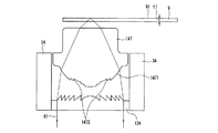
図5において144は対物レンズである。また、1441は対物レンズ144の光ディスクに直接対向しない面(第1面)、さらに、1442は第1面1441に形成した位相段差である。位相段差1442は、対物レンズ144の第1面1441の反対側の面(第2面)や、ホログラム134のいずれかの面に形成することも可能である。
In FIG. 5, 144 is an objective lens. Further, 1441 is a surface (first surface) of the
また、図5のように、対物レンズ144と一体化することにより、トラック追従などによって対物レンズ144が動いても、位相段差1442と対物レンズ144との相対位置が変化せず、光学的性能が劣化しないという効果を得ることができる。
Further, as shown in FIG. 5, by integrating with the
また、位相段差1442と対物レンズ144との相対位置変化による特性劣化が十分小さい場合には、対物レンズ144と位相段差1442を一体化せず、図1のコリメートレンズ8の表面などに形成する構成もあり得る。さらに、図示はしないが、ホログラム及び位相段差のいずれをも屈折型の対物レンズ表面に一体形成することも可能である。
In addition, when the characteristic deterioration due to the relative position change between the
図6は、位相段差1442を拡大した模式図である。1段あたりhaの高さの段差を1段以上形成する。段差haは、位相段差1442を形成する基材の屈折率nbを、波長λ1(例えば405nm)に対する屈折率としたときに、下記の式(1)を満足するようにしている。
FIG. 6 is an enlarged schematic diagram of the
式(1) ha=5×λ1/(nb−1)
式(1)は、下記の式(2)のように変形できる。
Expression (1) ha = 5 × λ1 / (nb−1)
Expression (1) can be transformed as the following Expression (2).
式(2) 5×λ1=ha×(nb−1)
式(2)の右辺は、高さhaの段差による光路長の差である。すなわち、位相段差1442の1段の段差は、波長λ1の光に対して、波長λ1の5倍の光路長の差、言い換えると10πラジアン(5×2π)の位相差を生じさせるように設定している。
Formula (2) 5 × λ1 = ha × (nb−1)
The right side of equation (2) is the difference in optical path length due to the step height of ha. That is, one step of the
例えば、位相段差1442を形成する基材がBK7と呼ばれる種類のガラスであれば、
λ1=405nmのとき、nb=1.5302であり、(式1)より、
ha=3819nm
となる。この段差に、例えば波長λ2=655nmの赤色光が入射すると、λ2=655nmに対するBK7の屈折率nrは1.5144なので、生じる光路長の差Lは下記のようになる。
For example, if the base material forming the
When λ1 = 405 nm, nb = 1.5302, and from (Equation 1),
ha = 3819 nm
It becomes. For example, when red light having a wavelength of λ2 = 655 nm is incident on the step, the refractive index nr of BK7 with respect to λ2 = 655 nm is 1.5144, and the resulting optical path length difference L is as follows.
L=ha×(nr−1)=1964.5
この算出値は、ほぼ3×λ2に等しい。すなわち、青色光に対して波長の5倍の光路長の差を生じる段差は、赤色光に対しては波長の3倍の光路長の差を生じることになる。波長の整数倍の光路長の差が生じる位相変化量は、2πラジアンの整数倍(λ1=405nmに対して10πラジアン、λ2=655nmに対しては6πラジアン)であるので、実質的には位相差を生じない。
L = ha × (nr−1) = 1964.5
This calculated value is approximately equal to 3 × λ2. In other words, a step that causes a difference in optical path length of 5 times the wavelength for blue light results in a difference in optical path length of 3 times the wavelength for red light. The amount of phase change that causes an optical path length difference that is an integral multiple of the wavelength is an integral multiple of 2π radians (10π radians for λ1 = 405 nm and 6π radians for λ2 = 655 nm). There is no phase difference.
したがって、λ1やλ2の基準波長に対しては波面の変化を生じさせない。そして、基準波長から例えば数nmの波長変化が起こると、光路長の差が波長の整数倍からずれるため、位相変化を生じる。段差は、図6の様に基材側へ堀込むことも、逆に、盛り上げることもできるので、波長ずれに対する位相変化の方向も自由に設定できる。例えば、青色光であれば、波長1nmの変化に対する位相変化量ΔφBは
ΔφB=10π/405=0.024π(ラジアン)
である。レンズやホログラムによって生じる波長1nm変化あたりの色収差が0.024πラジアンになる位置ごとにhaの高さの段差を積み重ねて形成することによって、収差を補正することができる。また、赤色光に対しては、波長1nmの変化に対する位相変化量ΔφRは、
ΔφB=6π/655=0.009π(ラジアン)
である。青色光に比べて赤色光では位相変化量が小さいが、レンズやホログラムによって生じる波長1nm変化あたりの色収差も小さいので問題ない。
Therefore, the wavefront does not change with respect to the reference wavelengths λ1 and λ2. When a wavelength change of, for example, several nm occurs from the reference wavelength, a phase change occurs because the difference in optical path length deviates from an integral multiple of the wavelength. As shown in FIG. 6, the step can be dug to the substrate side, or conversely, can be raised, so that the direction of the phase change with respect to the wavelength shift can be freely set. For example, in the case of blue light, the amount of phase change ΔφB with respect to a change in wavelength of 1 nm is ΔφB = 10π / 405 = 0.024π (radian).
It is. Aberrations can be corrected by stacking and forming a step having a height of ha at each position where the chromatic aberration per 1 nm wavelength change caused by a lens or hologram is 0.024π radians. For red light, the amount of phase change ΔφR with respect to a change in wavelength of 1 nm is
ΔφB = 6π / 655 = 0.09π (radian)
It is. The phase change amount of red light is smaller than that of blue light, but there is no problem because chromatic aberration per 1 nm wavelength change caused by a lens or hologram is also small.
なお、上記では基準波長として、青色は405nm、赤色は655nmを選んだが、青色の基準波長は408nmや410nmなど他の波長を選ぶことも可能であり、それに応じて単位段差haと赤色の基準波長も変えればよい。その関係は、下記の式(3)で表される。 In the above description, 405 nm for red and 655 nm for red are selected as the reference wavelengths. However, other wavelengths such as 408 nm and 410 nm can be selected for the blue reference wavelength, and the unit step ha and the red reference wavelength are accordingly selected. Can also be changed. The relationship is represented by the following formula (3).
式(3) ha=3×λ2/(n2−1)=5×λ1/(n1−1)
位相段差はhaを1単位とするが、その整数倍(2倍、3倍・・・)を1単位としても赤色と青色の両基準波長に対して波面変化を与えず、それぞれからの波長変化に対してのみ波面を変化させることができる。
Expression (3) ha = 3 × λ2 / (n2-1) = 5 × λ1 / (n1-1)
The phase difference is defined as ha as one unit, but even if the integral multiple (2 times, 3 times,...) Is set as one unit, the wavefront change is not applied to both the red and blue reference wavelengths, and the wavelength changes from each. The wavefront can be changed only for.
また、青色光に対して波長の5倍の光路長の差を生じる段差を、第1の従来例へ適用することによって、波長変化による色収差を補正する構成としてもよい。この構成では、位相段差は2種類の異なる材質で形成された対物レンズに形成されていることになる。この構成によれば、屈折型レンズによる色収差補正作用は、回折による光量損失回折による光量損失がなく、高い光利用効率と色収差補正とを両立できる。 Further, a step that generates a difference in optical path length of 5 times the wavelength with respect to the blue light may be applied to the first conventional example to correct chromatic aberration due to wavelength change. In this configuration, the phase step is formed on the objective lens formed of two different materials. According to this configuration, the chromatic aberration correcting action by the refractive lens has no light amount loss due to diffraction and can achieve both high light utilization efficiency and chromatic aberration correction.
さらに、波長変化による焦点位置変化をも補正することは、原理的には可能であるが、段差数が多くなり、一段あたりの平坦部の長さ(光束に沿った方向に同じ高さの部分。例えば図6のcの長さ)が狭くなり、設計通りに作製することが困難になる。したがって、図5に示したように、図2〜図4において説明したホログラムによって基材厚さと色収差による焦点距離変化を補正し、かつ、青色光に対して波長の5倍の光路長の差を生じる段差によって、色収差による球面収差を補正する構成により、容易に制作可能になり、設計どおりの性能を期待できるという効果を得ることができ、より好ましい。 Furthermore, although it is possible in principle to correct the focal position change due to the wavelength change, the number of steps increases, and the length of the flat portion per step (the portion of the same height in the direction along the light beam) For example, the length of c in FIG. Therefore, as shown in FIG. 5, the change in focal length due to the substrate thickness and chromatic aberration is corrected by the hologram described in FIGS. 2 to 4, and the difference in optical path length is 5 times the wavelength of blue light. A configuration in which spherical aberration due to chromatic aberration is corrected by the generated step makes it easy to produce, and the effect of expecting performance as designed is more preferable.
本実施の形態で示した、青色光ビームに対して波長の2倍の光路長の差を生み+2次回折を起こす深さの鋸歯状の断面形状を持つホログラムを利用して、赤色光ビームの+1次回折光によって異種ディスクの互換を実現し、かつ、青色光に対して波長の5倍の光路長の差を生じる段差によって、色収差による球面収差を補正する概念については、先に挙げたいずれの従来例にも開示されていない。 Using the hologram shown in this embodiment, which has a serrated cross-sectional shape with a depth that causes a difference in optical path length twice the wavelength of the blue light beam and causes second-order diffraction, the red light beam Regarding the concept of correcting spherical aberration due to chromatic aberration by realizing a difference in optical path length that is 5 times the wavelength of blue light by realizing interchangeability of different types of discs by + 1st order diffracted light, Neither is disclosed in the conventional example.
本実施の形態では、上記の新規な構成により、異種ディスクの互換を実現できる。さらに、青色光ビーム、赤色光ビームいずれに対してもホログラム134が凸レンズ作用をもち、回折作用は、色分散が、屈折作用とは逆方向であるので、屈折型の凸レンズである対物レンズ144と組み合わせたときに数nm以内の波長変化に対する色収差とりわけ焦点距離の波長依存性を相殺し低減できるという効果がある。さらに、色収差による球面収差も補正でき、波長の変化に対しても、安定に情報の再生や記録を行うことができる。
In the present embodiment, compatibility of different types of disks can be realized by the above-described new configuration. Further, since the
したがって、ホログラム134と位相段差だけで、異種ディスクの互換と色収差補正の課題を一挙に解決することができるという顕著な効果を有する。すなわち、瞬時の応答に適していない対物レンズのフォーカス制御によることなく、例えば再生から記録へ瞬時の変化による波長変化に瞬時に対応できることになる。
Therefore, only the
なお、図5と図6では対物レンズ(屈折型レンズ)144の表面に位相段差1442を形成する場合を例示したが、図7に示すように位相段差1462をホログラム136の基板表面へ形成することも可能である。この場合の位相段差部分の拡大図を図8に示す。位相段差の段差を青色光に対して波長の5倍の光路長の差を与える段差haの整数倍にする点は図6と同じである。本実施の形態に係る位相段差は、前記のように対物レンズやホログラム等の光学素子又は光学レンズに追加して形成してもよく、位相段差自体を独立した光学素子として形成してもよい。このことは以下の実施の形態においても同様である、
さらに、光ヘッド装置の全体構成としては、下記に付加的に有効な構成例を示す。下記は、本願実施の形態すべてにおいて有効である。ただし、本願の重要な点は、青色光に対して波長の5倍の光路長の差を生じる段差、及びこれに組み合わせて用いる対物レンズやホログラムにある。このため、それ以外に説明する構成は下記を含め、すでに説明した構成であるビームスプリッターや検出レンズ、検出ホログラムは必須のものではなく、好ましい構成としてそれぞれ効果を有するものの、それ以外の構成も適宜使用可能である。
5 and 6 illustrate the case where the
Further, as an overall configuration of the optical head device, an additional effective configuration example will be shown below. The following is effective in all the embodiments of the present application. However, an important point of the present application is a step that causes a difference in optical path length of 5 times the wavelength of blue light, and an objective lens or hologram used in combination therewith. For this reason, the configurations described in addition to the following, including the following, are the beam splitter, the detection lens, and the detection hologram, which are already described, are not indispensable. It can be used.
図1において、3ビーム格子(回折素子)3をさらに青色レーザー1からビームスプリッター4までの間に配置することにより光ディスク9のトラッキングエラー信号をよく知られたディファレンシャルプッシュプル(DPP)法によって検出することも可能である。
In FIG. 1, a tracking error signal of the
また、光軸に対して垂直な2方向をx方向とy方向と定義したときに、例えばx方向のみを拡大するようなビーム整形素子2をさらに青色レーザー1からビームスプリッター4までの間に配置することにより青色光ビーム61の遠視野像を光軸を中心に点対称形に近い強度分布に近づけることができ、光の利用効率の向上を図ることができる。ビーム整形素子2は、両面シリンドリカルレンズなどを用いることによって構成可能である。
Further, when two directions perpendicular to the optical axis are defined as an x direction and a y direction, for example, a
3ビーム格子(回折素子)22をさらに赤色レーザー20からビームスプリッター16までの間に配置することにより光ディスク10のトラッキングエラー信号をよく知られたディファレンシャルプッシュプル(DPP)法によって検出することも可能である。
It is also possible to detect the tracking error signal of the
また、コリメートレンズ8を光軸方向(図1の左右方向)へ動かすことにより光ビームの平行度を変化させることも有効である。基材の厚さ誤差や、光ディスク9が2層ディスクの場合に層間厚さに起因する基材厚さがあると球面収差が発生するが、このようにコリメートレンズ8を光軸方向に動かすことによってその球面収差を補正することができる。このように、コリメートレンズ8を動かすことによる球面収差の補正は、光ディスクに対する集光光のNAが0.85の場合に数100mλ程度可能であり、±30μmの基材厚さを補正することもできる。しかし、基材厚0.1mmに対応した対物レンズ14を用いて、DVDの記録
・再生を行う際には基材厚差を0.5mm以上補償する必要があり、コリメートレンズ8の移動だけでは球面収差補正能力が不足であり、ホログラム13(一例として134)による波面変換が必要である。ただし、赤色光ビームを用いて光ディスク10の記録・再生を行う場合に、コリメートレンズ8を図1の左側、すなわち赤色レーザー20へ近い側に移動しておくことによって、対物レンズ14へ向かう赤色光ビームを発散光にし、光ディスク10に対する集光スポットをより対物レンズ14から離すと共に、基材厚さによる収差の一部を補正し、ホログラム13に求められる収差補正量を低減してホログラムピッチを広くし、ホログラム13の作成を容易にすることもできる。
It is also effective to change the parallelism of the light beam by moving the collimating lens 8 in the optical axis direction (left-right direction in FIG. 1). Spherical aberration occurs when there is a substrate thickness error due to a substrate thickness error or when the
さらに、ビームスプリッター4を、青色レーザー1から出射する直線偏光の光を一部(例えば10%程度)透過するようにして、透過した光ビームをさらに集光レンズ6によって光検出器7へ導くと、光検出器7から得られる信号を用いて青色レーザー1の発光光量変化をモニターしたり、さらに、その光量変化をフィードバックして、青色レーザー1の発光光量を一定に保つ制御を行うこともできる。
Further, when the
さらに、ビームスプリッター4を、赤色レーザー1から出射する直線偏光の光を一部(例えば10%程度)反射するようにして、反射した光ビームをさらに集光レンズ6によって光検出器7へ導くと、光検出器7から得られる信号を用いて赤色レーザー20の発光光量変化をモニターしたり、さらに、その光量変化をフィードバックして、赤色レーザー20の発光光量を一定に保つ制御を行うこともできる。
Further, when the
(実施の形態2)
次に、本発明の実施の形態2を説明する。本実施の形態は、実施の形態1に比べて、ホログラム134の内周部134Cの格子断面形状のみを変更するものである。図9は実施の形態1で示したホログラム134の内周部134Cにおける一周期の格子断面形状を説明するものである。図9(a)は、物理的な形状を示している。図9(b)は、青色光に対する位相変調量を示している。図9(c)は、赤色光に対する位相変調量を示している。
(Embodiment 2)
Next, a second embodiment of the present invention will be described. In the present embodiment, only the lattice sectional shape of the inner peripheral portion 134C of the
図9(a)において縦方向は鋸歯状格子の深さを示している。図4と違って深さは、赤色光ビームを基準に決定する。nrは、赤色光ビームに対するホログラム材料の屈折率である。ホログラム材料を、例えば、BK7とすると、λ2=660nmに対しては、nr=1.5142である。 In FIG. 9A, the vertical direction indicates the depth of the sawtooth lattice. Unlike FIG. 4, the depth is determined based on the red light beam. nr is the refractive index of the hologram material for the red light beam. If the hologram material is, for example, BK7, nr = 1.5142 for λ2 = 660 nm.
鋸歯状格子の深さは、赤色光ビームに対して光路長の差が約1波長、すなわち位相差が約2πラジアンになる量にする。この場合、深さh2は、
h2=λ2/(nr−1)=1.28μmとなる。
The depth of the sawtooth grating is set so that the optical path length difference is about one wavelength with respect to the red light beam, that is, the phase difference is about 2π radians. In this case, the depth h2 is
h2 = λ2 / (nr−1) = 1.28 μm.
一方、青色光ビームに対するホログラム材料の屈折率をnbとすると、ホログラム材料がBK7の場合は、nb=1.5302となる。鋸歯状格子の深さh2による赤色光ビームに発生する光路長差は、h1×(nr−1)で表わされる。したがって、青色光ビームの波長λ1に対する光路長差の倍数は、λ1=405nm、nb=1.5302を代入して下記のようになる。 On the other hand, when the refractive index of the hologram material with respect to the blue light beam is nb, when the hologram material is BK7, nb = 1.5302. The optical path length difference generated in the red light beam depending on the depth h2 of the sawtooth grating is represented by h1 × (nr−1). Therefore, the multiple of the optical path length difference with respect to the wavelength λ1 of the blue light beam is as follows by substituting λ1 = 405 nm and nb = 1.5302.
h2×(nb-1)/λ1=1.68
すなわち、光路長差は波長λ1の約1.7倍となり、位相変調量は約3.35πラジアンとなる。このため、+2次回折光強度が最大となり、スカラー計算上は約80%の回折効率となる。
h2 × (nb-1) /λ1=1.68
That is, the optical path length difference is about 1.7 times the wavelength λ1, and the phase modulation amount is about 3.35π radians. For this reason, the intensity of the + 2nd order diffracted light is maximized, and the diffraction efficiency is about 80% in the scalar calculation.
図9(a)のように、格子一周期の形状を、深さh2の鋸歯状の断面形状にすると、青色光ビームは、先に説明したように+2次回折が最も強いので、回折角度を決める格子周期は、実質p4/2であり、位相変化は図9(b)と同等となる。そして、赤色光ビームに対しては、+1次回折が最も強く計算上は回折効率が100%になり、光の利用効率が高くできる。 As shown in FIG. 9A, when the shape of one period of the grating is a sawtooth cross-sectional shape having a depth h2, the blue light beam has the strongest + 2nd-order diffraction as described above. The grating period to be determined is substantially p4 / 2, and the phase change is equivalent to that in FIG. For the red light beam, the + 1st order diffraction is the strongest, and the diffraction efficiency is 100% in calculation, so that the light utilization efficiency can be increased.
また、青色回折光の回折効率は80%程度に下がるが、中心部の光量が下がると相対的に外周部分の光量が上がることになる。半導体レーザー光源の遠視野像は外周部分ほど強度が低くその一部しか使用できないが、このように内周部分の光量が下がると、遠視野像の、より広い範囲を使用できるので、光の利用効率を向上させることができる。 Further, the diffraction efficiency of the blue diffracted light decreases to about 80%, but when the light amount in the central portion decreases, the light amount in the outer peripheral portion relatively increases. The far-field image of the semiconductor laser light source has a lower intensity at the outer periphery and only a part of it can be used, but if the amount of light at the inner periphery decreases in this way, a wider range of the far-field image can be used. Efficiency can be improved.
これは、コリメートレンズ8の焦点距離を短くすることによって実現できるが、これによって、内周部分の光量低下分を補うことが可能である。したがって、本実施の形態の、内周部分を図9を用いて説明したように高さh2として、赤色光ビームの回折光強度を最大にするという効果を得ることができ、かつ、このときに青色光ビームの集光スポットに対する光の利用効率も低下しないという効果を得ることができる。 This can be realized by shortening the focal length of the collimating lens 8, but this makes it possible to compensate for the light amount decrease in the inner peripheral portion. Therefore, the effect of maximizing the diffracted light intensity of the red light beam can be obtained by setting the inner peripheral portion of the present embodiment to the height h2 as described with reference to FIG. The effect that the utilization efficiency of the light with respect to the condensing spot of the blue light beam is not lowered can be obtained.
そして、実施の形態1と同様に青色光に対して波長の5倍の光路長の差を生じる段差と組み合わせることにより色収差による球面収差を補正することができる。 Then, in the same manner as in the first embodiment, the spherical aberration due to chromatic aberration can be corrected by combining with a step that produces a difference in optical path length of 5 times the wavelength of blue light.
本実施の形態のホログラムも、青色光ビーム、赤色光ビームいずれに対してもホログラム134が凸レンズ作用をもつ。回折作用は、色分散が、屈折作用とは逆方向であるので、屈折型の凸レンズである対物レンズ144と組み合わせたときに数nm以内の波長変化に対する色収差とりわけ焦点距離の波長依存性を相殺し低減できるという効果がある。
In the hologram of the present embodiment, the
そして、青色光に対して波長の5倍の光路長の差を生じる段差と組み合わせることにより異種ディスクの互換と色収差補正という課題を一挙に解決することができるという顕著な効果を有する。 Further, by combining with a step that generates a difference in optical path length of 5 times the wavelength with respect to blue light, there is a remarkable effect that the problems of compatibility of different types of disks and correction of chromatic aberration can be solved at once.
また、高いNAのレンズは製作の難易度が高いが、ホログラムが凸レンズ作用を受け持つことにより組み合わせる屈折型の対物レンズ144の製作難易度を緩和できるという効果もある。
In addition, although a lens with a high NA is highly difficult to manufacture, there is also an effect that the manufacturing difficulty of the refraction
さらに、光ヘッド装置の全体構成としては、実施の形態1において付加的に述べた構成を組み合わせることも可能である。 Furthermore, the overall configuration of the optical head device can be combined with the configuration additionally described in the first embodiment.
(実施の形態3)
次に、本発明の実施の形態3を説明する。本実施の形態3は、実施の形態1、2と同様に、光ヘッド装置の全体構成例としては図1を挙げることができ、共通である。図1において、ホログラム13の構成が異なるので、図10−12を用いて、実施の形態3の特徴的な要素であるホログラム135の働きと構成を説明する。
(Embodiment 3)
Next, a third embodiment of the present invention will be described. In the third embodiment, as in the first and second embodiments, FIG. 1 can be given as an example of the overall configuration of the optical head device, and is common. In FIG. 1, since the configuration of the hologram 13 is different, the function and configuration of the
図10、11において、135はホログラムである。内周部135Cは例えば、実施の形態1において示したホログラム134の内周部134Cと同じである。図12は、ホログラム135の外周部135Bのホログラム格子の一周期(p7)の間の断面を説明する図である。図12(a)は、物理的な形状を示している。図12(b)は、青色光に対する位相変調量を示している。図12(c)は、赤色光に対する位相変調量を示している。
10 and 11,
図12(a)において、縦方向は鋸歯形状の深さを示している。鋸歯形状の深さh3は、青色光ビームに対して光路長の差が約1波長、すなわち位相差が約2πラジアンになる量とする。nbを青色光ビームに対するホログラム材料の屈折率とすると、ホログラム材料が例えばBK7の場合、nb=1.5302であり、鋸歯形状の深さh3は、
h3=λ1/(nb−1)=0.764μmとなる。
In FIG. 12A, the vertical direction indicates the depth of the sawtooth shape. The sawtooth-shaped depth h3 is set so that the optical path length difference is about one wavelength with respect to the blue light beam, that is, the phase difference is about 2π radians. When nb is a refractive index of the hologram material with respect to the blue light beam, when the hologram material is, for example, BK7, nb = 1.5302, and the sawtooth-shaped depth h3 is
h3 = λ1 / (nb−1) = 0.664 μm.
一方、赤色光ビームに対するホログラム材料の屈折率をnrとすると、ホログラム材料がBK7の場合は、nr=1.5142となる。深さh3による赤色光ビームに発生する光路長差は、h3×(nr−1)で表わされる。したがって、赤色光ビームの波長λ2に対する光路長差の倍数は、λ2=660nm、nr=1.5142を代入して下記のようになる。 On the other hand, when the refractive index of the hologram material with respect to the red light beam is nr, when the hologram material is BK7, nr = 1.5142. The optical path length difference generated in the red light beam with the depth h3 is represented by h3 × (nr−1). Therefore, the multiple of the optical path length difference with respect to the wavelength λ2 of the red light beam is as follows by substituting λ2 = 660 nm and nr = 1.5142.
h3×(nr−1)/λ2=0.595
すなわち、光路長差は波長λ2の約0.6倍となり、位相変調量は約1.2πラジアンとなる。したがって+1次回折光強度が最も強くなり約60%となる。
h3 × (nr−1) /λ2=0.595
That is, the optical path length difference is about 0.6 times the wavelength λ2, and the phase modulation amount is about 1.2π radians. Accordingly, the intensity of the + 1st order diffracted light is the strongest and is about 60%.
このように、図12(a)のように、格子一周期の形状を、深さh3の鋸歯状の断面形状にすると、青色光ビームは、+1次回折が最も強い(実施の形態1や2では外周部においても+2次回折光が最も強いが、本実施の形態はこの点が異なる)ので、回折角度を決める格子周期は、実質p7であり、位相変化は図12(b)と同等となる。そして、赤色光ビームに対しても+1次回折が最も強く、回折角度を決める格子周期は、やはり実質p7である。 Thus, as shown in FIG. 12A, when the shape of one period of the grating is a sawtooth cross-sectional shape having a depth h3, the blue light beam has the strongest + 1st order diffraction (Embodiments 1 and 2). In this case, + 2nd order diffracted light is the strongest also in the outer peripheral portion, but this embodiment is different in this point), so the grating period for determining the diffraction angle is substantially p7, and the phase change is equivalent to FIG. . The + 1st order diffraction is the strongest for the red light beam, and the grating period for determining the diffraction angle is substantially p7.
ホログラム135の外周部135Bは青色光ビームが約0.1mmの基材厚を通して集光されるように設計する。このとき、赤色光ビームも青色光ビームと同じ回折次数の+1次回折を受け、赤色の波長λ2が青色の波長λ1よりも長いので回折角度は大きくなる。
The
ホログラムのブレーズ方向は内周部同様に凸レンズ作用を持つように設計する。このとき、赤色光ビームの方が回折角度が大きいので、強い凸レンズ作用を受ける。これは、内周部(例えば134C)において、赤色光ビームの方が青色光ビームよりも、弱い凸レンズ作用を受ける、又は凹レンズ作用を受ける(131C等)のとは全く異なる。 The blazing direction of the hologram is designed so as to have a convex lens action like the inner periphery. At this time, since the red light beam has a larger diffraction angle, it receives a strong convex lens action. This is completely different from the case where the red light beam receives a weak convex lens action or a concave lens action (131C or the like) in the inner periphery (for example, 134C) than the blue light beam.
このため、外周部135Bによって回折される赤色光ビームは内周部を通る赤色光ビームと同じ場所に集光されない。このようにして、光ディスク9を青色光ビームによって記録・再生するときの開口数NAbを、光ディスク10を赤色光ビームによって記録・再生するときの開口数NArよりも大きく(NAb>NAr)することができる。
For this reason, the red light beam diffracted by the outer
そして、実施の形態1と同様に青色光に対して波長の5倍の光路長の差を生じる段差と組み合わせることにより色収差による球面収差を補正することができる。 Then, in the same manner as in the first embodiment, the spherical aberration due to chromatic aberration can be corrected by combining with a step that produces a difference in optical path length of 5 times the wavelength of blue light.
さらに、光ヘッド装置の全体構成としては、実施の形態1において付加的に述べた構成を組み合わせることも可能である。 Furthermore, the overall configuration of the optical head device can be combined with the configuration additionally described in the first embodiment.
(実施の形態4)
図13は、本発明の実施の形態4に係る光ヘッド装置の要部概略断面図を示している。本図に示した光ヘッド装置は、図5の構成において、ホログラム134に代えて液晶型位相変調素子を用いたものである。
(Embodiment 4)
FIG. 13 shows a schematic cross-sectional view of a main part of an optical head device according to
液晶型位相変調素子137は、電圧を印加したり切ったりできる。すなわち液晶型位相変調素子137を電気的にスイッチングすることにより、透過波面に与える位相変調量を切り替えて基材厚差による収差を補正することができる。
The liquid crystal type
この場合、液晶型位相変調素子137では、波長変化によって生じる収差(軸上色収差、球面収差とも)を補正することはできない。そこで、位相段差1442を組み合わせることによって、軸上色収差と球面収差を含めた色収差をすべて補正する構成としている。
In this case, the liquid crystal type
位相段差1442は、前記の図5に示した位相段差1442と同様の構成であり、波長λ1の青色光に対して5λ1、波長λ2の赤色光に対して3λ2の光路長差を生じさせる段差を単位段差とする位相段差である。
The
例えば、対物レンズ144が青色波長変動1nmに対してその5倍の5nmの収差を生じる毎に位相段差を1段形成すれば、青色に対する色収差を補正することができる。赤色光についても、色収差は同じ方向に生じるのでこれを同様に補正できる。
For example, if the
(実施の形態5)
図14は、本発明の実施の形態5に係る光ヘッド装置の要部概略断面図を示している。前記実施の形態1−4では、青色の波長λ1の5倍の位相差を生じる段差を単位段差とする位相段差と、回折型のホログラム又は液晶型位相変調素子とを組み合わせた実施の形態を説明した。本実施の形態は、単一の光ディスクの記録再生を前提とするものである。このため、位相段差の1段は、波長の5倍の位相差を生じる段差に限らず、波長の整数倍の位相差を生じる段差としている。
(Embodiment 5)
FIG. 14 is a schematic cross-sectional view of the main part of an optical head device according to Embodiment 5 of the present invention. In Embodiment 1-4 described above, an embodiment in which a phase step having a step that generates a phase difference of 5 times the blue wavelength λ1 as a unit step and a diffractive hologram or liquid crystal type phase modulation element is described. did. This embodiment is premised on recording / reproduction of a single optical disc. For this reason, one step of the phase step is not limited to a step that generates a phase difference of 5 times the wavelength, but is a step that generates a phase difference of an integral multiple of the wavelength.
図14に示した光ヘッド装置は、位相段差1472を形成した対物レンズ147とホログラム134とを組み合わせたものであり、図5の光ヘッド装置と同一構成のものは、同一符号を付している。本図に示した光ヘッド装置は、青色の波長λ1に光ディスク9を記録再生する装置であり、対物レンズ147の面1471に形成した位相段差1472の位相段差の1段は、波長λ1の整数倍の位相差を生じる段差としている。
The optical head device shown in FIG. 14 is a combination of an
この構成においても、色収差を補正できる。また、ホログラム134は位相段差1472と色収差補正を分担できるので、ホログラム134の格子ピッチを粗くすることができ、光量の利用効率を高めることができるという効果を得ることができる。
Even in this configuration, chromatic aberration can be corrected. In addition, since the
(実施の形態6)
本発明の光ヘッド装置を用いた光情報装置の実施の形態を、図15に示す。図15において光ディスク9は、ターンテーブル82に乗せられ、モータ64によって回転される。実施の形態1−4に示した光ヘッド装置55は、光ディスク9の所望の情報の存在するトラックのところまで、光ヘッド装置の駆動装置51によって粗動される。
(Embodiment 6)
An embodiment of an optical information device using the optical head device of the present invention is shown in FIG. In FIG. 15, the
光ヘッド装置55は、光ディスク9との位置関係に対応して、フォーカスエラー(焦点誤差)信号やトラッキングエラー信号を電気回路53へ送る。電気回路53はこの信号に対応して、光ヘッド装置55へ、対物レンズを微動させるための信号を送る。この信号によって、光ヘッド装置55は、光ディスク9に対してフォーカス制御とトラッキング制御とを行い、光ヘッド装置55によって、情報の読み出し、書き込み(記録)又は消去を行う。
The
以上の説明は、搭載する光ディスクを光ディスク9より基材厚の厚い光ディスク10に交換しても同様である。本実施の形態の光情報装置は、光ヘッド装置として、前記本発明の光ヘッド装置を用いるので、単一の光ヘッド装置によって、記録密度の異なる複数の光ディスクに対応することができる。
The above description is the same even if the optical disk to be mounted is replaced with the
なお、光ヘッド装置55を実施の形態5のように、単一の光ディスク専用としたものでもよい。このことは、以下の実施の形態7−10においても同様である。
The
(実施の形態7)
本実施の形態は、前記実施の形態6に係る光情報装置67を具備したコンピューターの実施の形態である。図16は、本実施の形態に係るコンピューターの斜視図である。
(Embodiment 7)
The present embodiment is an embodiment of a computer provided with the
本図に示したコンピューター100は、実施の形態6に係る光情報装置67と、情報の入力を行うためのキーボードマウス又はタッチパネルなどの入力装置65と、入力装置65から入力された情報や、光情報装置67から読み出した情報などに基づいて演算を行う中央演算装置(CPU)などの演算装置64と、演算装置64によって演算された結果などの情報を表示するブラウン管や液晶表示装置、プリンターなどの出力装置81とを備えている。
The
本実施の形態に係るコンピューターは、前記実施の形態6に係る光情報装置67を具備しており、異なる種類の光ディスクを安定に記録又は再生できるので、広い用途に使用できる。
The computer according to the present embodiment includes the
(実施の形態8)
本実施の形態は、前記実施の形態6に係る光情報装置67を具備した光情報媒体(光ディスク)プレーヤーの実施の形態である。図17は、本実施の形態に係る光情報媒体プレーヤーの斜視図である。
(Embodiment 8)
The present embodiment is an embodiment of an optical information medium (optical disk) player provided with the
本図に示した光ディスクプレーヤー121は、実施の形態6の光情報装置67と、光情報装置67から得られる情報信号を画像に変換する情報から画像への変換装置66(例えばデコーダー)を備えている。本構成はカーナビゲーションシステムとしても利用できる。また、液晶モニターなどの表示装置120を加えた形態も可能である。
The
本実施の形態に係る光情報媒体(光ディスク)プレーヤーは、前記実施の形態6に係る光情報装置67を具備しており、異なる種類の光ディスクを安定に記録又は再生できるので、広い用途に使用できる。
The optical information medium (optical disc) player according to the present embodiment includes the
(実施の形態9)
本実施の形態は、前記実施の形態6に係る光情報装置67を具備した光情報媒体(光ディスク)レコーダーの実施の形態である。図18は、本実施の形態に係る光ディスクレコーダーの斜視図である。
(Embodiment 9)
The present embodiment is an embodiment of an optical information medium (optical disk) recorder provided with the
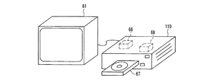
本図に示した光ディスクレコーダー110は、実施の形態6に係る光情報装置67と、画像情報を光情報装置67によって光ディスクへ記録する情報に変換する画像から情報への変換装置68(例えばエンコーダー)を備えている。
The
光情報装置67から得られる情報信号を画像に変換する情報から画像への変換装置66(デコーダー)も有することが好ましい。この構成によれば、既に記録した部分を再生することも可能となる。さらに、情報を表示するブラウン管、液晶表示装置又はプリンターなどの出力装置61を備えてもよい。
It is also preferable to have an information-to-image conversion device 66 (decoder) that converts an information signal obtained from the
本実施の形態に係る光ディスクレコーダーは、前記実施の形態6に係る光情報装置67を具備しており、異なる種類の光ディスクを安定に記録又は再生できるので、広い用途に使用できる。
The optical disc recorder according to the present embodiment includes the
(実施の形態10)
本実施の形態は、前記実施の形態6に係る光情報装置67を具備した光情報装置の実施の形態である。図19は、本実施の形態に係る光情報装置の斜視図である。
(Embodiment 10)
The present embodiment is an embodiment of an optical information device that includes the
本図に示した光情報装置は、前記実施の形態6に係る光情報装置67を備えている。入出力端子69は、光情報装置67に記録する情報を取り込んだり、光情報装置67によって読み出した情報を外部に出力する有線又は無線の入出力端子である。これによって、ネットワーク、すなわち複数の機器、例えばコンピューター、電話、テレビチューナーなどと情報をやりとりし、これら複数の機器から共有の情報サーバー(光情報媒体(光ディスク)サーバー)、として利用することが可能となる。情報を表示するブラウン管や液晶表示装置、プリンターなどの出力装置81を備えてもよい。
The optical information device shown in the figure includes the
本実施の形態に係る光情報装置は、前記実施の形態6に係る光情報装置67を具備しており、異なる種類の光ディスクを安定に記録又は再生できるので、広い用途に使用できる。
The optical information device according to the present embodiment includes the
さらに、複数の光ディスクを光情報装置67に出し入れするチェンジャー131を具備することにより、多くの情報を記録・蓄積できることになる。
る。
Furthermore, by providing the
The
なお、前記実施の形態7−10において図16−19には出力装置81や液晶モニター120を示したが、出力端子を備えて、出力装置81や液晶モニター120は持たず、別売りとする商品形態があり得ることはいうまでもない。
In addition, although the
また、図17と図18には入力装置は図示していないが、キーボードやタッチパネル、マウス、リモートコントロール装置など入力装置も具備した商品形態も可能である。逆に、前記実施の形態7−10において、入力装置は別売りとして、入力端子のみを持った形態も可能である。 Moreover, although an input device is not shown in FIGS. 17 and 18, a product form including an input device such as a keyboard, a touch panel, a mouse, and a remote control device is also possible. On the contrary, in Embodiments 7 to 10, the input device may be sold separately, and only the input terminal may be provided.
以上のように、本発明によれば、異なる種類の光ディスクの互換再生や互換記録を単一の対物レンズを用いて実現し、かつ光量切り替え時などの波長変化に際して、焦点距離の変化や球面収差の発生を抑制し、安定した情報の再生又は記録ができるので、光ヘッド装置、光情報装置、コンピューター、光情報媒体プレーヤー、カーナビゲーションシステム、光情報媒体レコーダー、光情報媒体サーバーに有用である。 As described above, according to the present invention, compatible reproduction and recording of different types of optical disks can be realized by using a single objective lens, and the focal length change and spherical aberration can be changed at the time of wavelength change such as when the amount of light is switched. Therefore, it is useful for optical head devices, optical information devices, computers, optical information media players, car navigation systems, optical information media recorders, and optical information media servers.
1,20 レーザー光源
2 ビーム整形素子
3,22 3ビーム格子
4,16 ビームスプリッター
5 1/4波長板
6 集光レンズ
7 光検出器
8 コリメートレンズ
9,10 光ディスク
13 ホログラム
14,144,145,146,147 対物レンズ
15 駆動手段
32 検出レンズ
33 光検出器
51 光ヘッド装置の駆動装置
53 電気回路
55 光ヘッド装置
64 演算装置
65 入力装置
66 デコーダー
67 光情報装置
68 エンコーダー
69 入出力端子
77 光ディスクプレーヤー(又はカーナビゲーションシステム)
81 出力装置
100 コンピューター
110 光ディスクレコーダー
130 光ディスクサーバー
1442,1462,1472 位相段差
DESCRIPTION OF
81
Claims (18)
前記光学レンズは、屈折型レンズと、ホログラムと、複数の段差を有する位相段差と、を備え、
前記390nm〜415nmから選ばれた青色光の基準波長λ1、前記630nm〜680nmから選ばれた赤色光の基準波長λ2、前記位相段差の前記基準波長λ1に対する屈折率nb、前記基準波長λ2に対する屈折率nrは、
3×λ2/(nr−1)=5×λ1/(nb−1)を満たし、
前記段差の高さhaは、ha=5×λ1/(nb−1)であり、
前記位相段差は、前記屈折型レンズ又は前記屈折型レンズと前記ホログラムによって生じる波長1nm変化あたりの色収差が一定量となる位置ごとに、前記haの高さの段差が積み重ねられており、
波長の変化によって、前記屈折型レンズ又は前記屈折型レンズと前記ホログラムとに生じる収差を、前記位相段差に生じる収差によって減じ、
前記青色光は前記光学レンズによって基材厚がt1の基材を通して集光され、前記赤色光は基材厚がt1より厚いt2の基材を通して集光されることを特徴とする光学レンズ。 An optical lens corresponding to at least two wavelengths of blue light having a wavelength of 390 nm to 415 nm and red light having a wavelength of 630 to 680 nm,
The optical lens includes a refractive lens, a hologram, and a phase step having a plurality of steps,
The reference wavelength λ1 of blue light selected from 390 nm to 415 nm, the reference wavelength λ2 of red light selected from the 630 nm to 680 nm, the refractive index nb to the reference wavelength λ1 of the phase step, and the refractive index to the reference wavelength λ2 nr is
3 × λ2 / (nr−1) = 5 × λ1 / (nb−1) is satisfied,
The height ha of the step is ha = 5 × λ 1 / (nb−1),
The phase step is formed by stacking steps having a height of ha for each position where the chromatic aberration per 1 nm wavelength change caused by the refractive lens or the refractive lens and the hologram becomes a certain amount,
Due to the change in wavelength, the aberration generated in the refractive lens or the refractive lens and the hologram is reduced by the aberration generated in the phase step,
The optical lens is characterized in that the blue light is collected by the optical lens through a base material having a base material thickness t1, and the red light is condensed through a base material having a base material thickness t2 larger than the base material thickness t1.
内周部に形成される前記鋸歯状格子の深さがh1であり、前記h1は、前記青色光に対して約2波長の光路長の差を与え、かつ、前記赤色光に対して約1波長の光路長の差を与える深さであり、
前記青色光は、基材厚t1の基材を通して集光し、前記青色光の波長λ1が変化したときの焦点距離変化を低減させるように、前記ホログラムを凸レンズ型にして、前記青色光が前記ホログラムにより凸レンズ作用を受けるようにし、
前記青色光が前記基材厚t1の基材を通して集光するときは、前記赤色光が前記基材厚t2の基材を通して集光するときに比べて、前記ホログラムによる凸レンズ作用を大きくして、前記赤色光の前記基材側の焦点位置を、前記青色光の前記基材側の焦点位置に比べて、前記光学レンズより離す請求項1に記載の光学レンズ。 The hologram is formed on an inner peripheral portion including at least an intersection with the optical axis of the hologram, and includes a sawtooth grating having a sawtooth cross-sectional shape. Depending on the depth of the sawtooth grating, the wavelength is 390 nm to + 2nd order diffracted light is generated most strongly for blue light having a wavelength of 415 nm, and + 1st order diffracted light is generated most strongly for red light having a wavelength of 630 to 680 nm.
The depth of the sawtooth grating formed on the inner periphery is h1, and the h1 gives a difference in optical path length of about two wavelengths with respect to the blue light, and about 1 with respect to the red light. It is the depth that gives the difference in optical path length of the wavelength,
The blue light is condensed through a base material having a base material thickness t1, and the hologram is formed into a convex lens type so as to reduce a change in focal length when the wavelength λ1 of the blue light is changed. So that it receives the convex lens action by the hologram,
When the blue light is condensed through the substrate having the substrate thickness t1, the convex lens action by the hologram is increased as compared with the case where the red light is condensed through the substrate having the substrate thickness t2. The optical lens according to claim 1, wherein a focal position of the red light on the base material side is separated from the optical lens as compared with a focal position of the blue light on the base material side.
前記外周部の前記ホログラム格子は鋸歯状断面形状の鋸歯状格子であり、前記外周部の鋸歯状格子の深さはh3であり、前記h3は、前記青色光に対して約1波長の光路長の差を与える深さであり、
前記外周部においては、前記青色光に対して+1次回折光が最も強く発生し、赤色光に対しても+1次回折光が最も強く発生する請求項4に記載の光学レンズ。 A hologram grating is further formed on the outer peripheral portion outside the inner peripheral portion,
The hologram grating at the outer peripheral portion is a sawtooth grating having a sawtooth cross-sectional shape, the depth of the sawtooth grating at the outer peripheral portion is h3, and h3 is an optical path length of about one wavelength with respect to the blue light. Is the depth that gives the difference of
5. The optical lens according to claim 4, wherein in the outer peripheral portion, the + 1st order diffracted light is generated most strongly with respect to the blue light, and the + 1st order diffracted light is generated most strongly with respect to the red light.
前記青色光を出射する第1レーザー光源と、
前記赤色光を出射する第2レーザー光源と、
光情報媒体の記録面上で反射した光ビームを受けてその光量に応じて電気信号を出力する光検出部とを備えたことを特徴とする光ヘッド装置。 An optical lens according to any one of claims 1 to 10 ,
A first laser light source that emits the blue light;
A second laser light source that emits the red light;
An optical head device comprising: a light detection unit that receives a light beam reflected on a recording surface of an optical information medium and outputs an electric signal according to the amount of light.
光情報媒体を回転するモーターと、
前記光ヘッド装置から得られる信号を受け前記信号に基づいて、前記モーター、前記光学レンズ、及び前記レーザー光源の少なくともいずれかを制御及び駆動する電気回路とを備えたことを特徴とする光情報装置。 An optical head device according to any one of claims 11 to 13 ,
A motor that rotates an optical information medium;
An optical information device comprising: an electric circuit that receives and receives a signal obtained from the optical head device, and controls and drives at least one of the motor, the optical lens, and the laser light source based on the signal .
入力された情報、及び前記光情報装置から再生された情報の少なくともいずれかに基づいて演算を行う演算装置と、
前記入力された情報、前記光情報装置から再生された情報、及び前記演算装置によって演算された結果の少なくともいずれかを出力する出力装置を備えたことを特徴とするコンピュータ。 An optical information device according to claim 14 or 15 ,
A computing device that performs computation based on at least one of the input information and the information reproduced from the optical information device;
A computer comprising: an output device that outputs at least one of the input information, information reproduced from the optical information device, and a result calculated by the arithmetic device.
Priority Applications (1)
| Application Number | Priority Date | Filing Date | Title |
|---|---|---|---|
| JP2003389677A JP4467957B2 (en) | 2002-11-25 | 2003-11-19 | Optical lens, optical head device, optical information device, computer, optical information medium player, optical information medium server |
Applications Claiming Priority (2)
| Application Number | Priority Date | Filing Date | Title |
|---|---|---|---|
| JP2002340589 | 2002-11-25 | ||
| JP2003389677A JP4467957B2 (en) | 2002-11-25 | 2003-11-19 | Optical lens, optical head device, optical information device, computer, optical information medium player, optical information medium server |
Publications (3)
| Publication Number | Publication Date |
|---|---|
| JP2004192783A JP2004192783A (en) | 2004-07-08 |
| JP2004192783A5 JP2004192783A5 (en) | 2005-07-14 |
| JP4467957B2 true JP4467957B2 (en) | 2010-05-26 |
Family
ID=32774730
Family Applications (1)
| Application Number | Title | Priority Date | Filing Date |
|---|---|---|---|
| JP2003389677A Expired - Lifetime JP4467957B2 (en) | 2002-11-25 | 2003-11-19 | Optical lens, optical head device, optical information device, computer, optical information medium player, optical information medium server |
Country Status (1)
| Country | Link |
|---|---|
| JP (1) | JP4467957B2 (en) |
Families Citing this family (7)
| Publication number | Priority date | Publication date | Assignee | Title |
|---|---|---|---|---|
| JP2005174416A (en) * | 2003-12-09 | 2005-06-30 | Konica Minolta Opto Inc | Diffraction optical element, objective optical system, optical pickup device and optical information recording reproducing device |
| JP2006092720A (en) * | 2004-08-25 | 2006-04-06 | Konica Minolta Opto Inc | Objective optical device, optical pickup device, and optical disk driving device |
| KR20070095281A (en) | 2005-01-20 | 2007-09-28 | 마츠시타 덴끼 산교 가부시키가이샤 | Optical pickup and optical disk device having this pickup |
| US8064314B2 (en) | 2005-07-28 | 2011-11-22 | Panasonic Corporation | Optical head and optical disc device |
| JP5360625B2 (en) * | 2012-02-08 | 2013-12-04 | 住友電工ハードメタル株式会社 | Laser microlenses |
| WO2014203526A1 (en) * | 2013-06-19 | 2014-12-24 | パナソニックIpマネジメント株式会社 | Optical information device and information processing device |
| JP5810300B2 (en) | 2013-06-21 | 2015-11-11 | パナソニックIpマネジメント株式会社 | Optical disc information apparatus and information processing apparatus |
-
2003
- 2003-11-19 JP JP2003389677A patent/JP4467957B2/en not_active Expired - Lifetime
Also Published As
| Publication number | Publication date |
|---|---|
| JP2004192783A (en) | 2004-07-08 |
Similar Documents
| Publication | Publication Date | Title |
|---|---|---|
| US7920310B2 (en) | Complex objective lens for an optical head and optical information apparatus | |
| US8509047B2 (en) | Optical head device and optical information device using the same, computer, optical disk player, car navigation system, optical disk recorder, and optical disk server | |
| US7248409B2 (en) | Optical element, optical lens, optical head apparatus, optical information apparatus, computer, optical information medium player, car navigation system, optical information medium recorder, and optical information medium server | |
| JP3993837B2 (en) | Compound objective lens, optical head device, optical information device, computer, optical disk player, car navigation system, optical disk recorder, optical disk server | |
| JP5053090B2 (en) | Optical head and optical disk apparatus | |
| JPWO2011048733A1 (en) | Optical head device, optical information device, and information processing device | |
| JP4467957B2 (en) | Optical lens, optical head device, optical information device, computer, optical information medium player, optical information medium server | |
| JP4336222B2 (en) | Optical head device, optical information device using the same, computer, optical disk player, car navigation system, optical disk recorder, and optical disk server | |
| JP3993870B2 (en) | Compound objective lens, optical head device, optical information device, computer, optical disk player, car navigation system, optical disk recorder, optical disk server | |
| JP4362068B2 (en) | OPTICAL ELEMENT, OPTICAL HEAD DEVICE USING SAME, OPTICAL INFORMATION DEVICE USING THE OPTICAL HEAD DEVICE, COMPUTER, OPTICAL PLAYER, CAR NAVIGATION SYSTEM, OPTICAL DISC RECORDER, AND OPTICAL DISK SERVER USING THE OPTICAL INFORMATION DEVICE | |
| JP2010040136A (en) | Composite objective lens, optical head device, optical information apparatus and optical disc system | |
| JP5340396B2 (en) | Objective lens element | |
| WO2011033791A1 (en) | Objective lens element | |
| JP2006004570A (en) | Optical lens, optical head, optical information apparatus, computer, optical information medium recorder |
Legal Events
| Date | Code | Title | Description |
|---|---|---|---|
| A521 | Request for written amendment filed |
Free format text: JAPANESE INTERMEDIATE CODE: A523 Effective date: 20050127 |
|
| A621 | Written request for application examination |
Free format text: JAPANESE INTERMEDIATE CODE: A621 Effective date: 20060615 |
|
| A977 | Report on retrieval |
Free format text: JAPANESE INTERMEDIATE CODE: A971007 Effective date: 20081112 |
|
| A131 | Notification of reasons for refusal |
Free format text: JAPANESE INTERMEDIATE CODE: A131 Effective date: 20081118 |
|
| A521 | Request for written amendment filed |
Free format text: JAPANESE INTERMEDIATE CODE: A523 Effective date: 20090114 |
|
| A131 | Notification of reasons for refusal |
Free format text: JAPANESE INTERMEDIATE CODE: A131 Effective date: 20090721 |
|
| A521 | Request for written amendment filed |
Free format text: JAPANESE INTERMEDIATE CODE: A523 Effective date: 20090918 |
|
| A131 | Notification of reasons for refusal |
Free format text: JAPANESE INTERMEDIATE CODE: A131 Effective date: 20091029 |
|
| A521 | Request for written amendment filed |
Free format text: JAPANESE INTERMEDIATE CODE: A523 Effective date: 20091221 |
|
| TRDD | Decision of grant or rejection written | ||
| A01 | Written decision to grant a patent or to grant a registration (utility model) |
Free format text: JAPANESE INTERMEDIATE CODE: A01 Effective date: 20100202 |
|
| A01 | Written decision to grant a patent or to grant a registration (utility model) |
Free format text: JAPANESE INTERMEDIATE CODE: A01 |
|
| A61 | First payment of annual fees (during grant procedure) |
Free format text: JAPANESE INTERMEDIATE CODE: A61 Effective date: 20100224 |
|
| R150 | Certificate of patent or registration of utility model |
Ref document number: 4467957 Country of ref document: JP Free format text: JAPANESE INTERMEDIATE CODE: R150 Free format text: JAPANESE INTERMEDIATE CODE: R150 |
|
| FPAY | Renewal fee payment (event date is renewal date of database) |
Free format text: PAYMENT UNTIL: 20130305 Year of fee payment: 3 |
|
| FPAY | Renewal fee payment (event date is renewal date of database) |
Free format text: PAYMENT UNTIL: 20130305 Year of fee payment: 3 |
|
| FPAY | Renewal fee payment (event date is renewal date of database) |
Free format text: PAYMENT UNTIL: 20140305 Year of fee payment: 4 |
|
| EXPY | Cancellation because of completion of term |