JP4467474B2 - Floor joint device - Google Patents
Floor joint device Download PDFInfo
- Publication number
- JP4467474B2 JP4467474B2 JP2005196317A JP2005196317A JP4467474B2 JP 4467474 B2 JP4467474 B2 JP 4467474B2 JP 2005196317 A JP2005196317 A JP 2005196317A JP 2005196317 A JP2005196317 A JP 2005196317A JP 4467474 B2 JP4467474 B2 JP 4467474B2
- Authority
- JP
- Japan
- Prior art keywords
- joint
- floor
- joint plate
- tip
- supported
- Prior art date
- Legal status (The legal status is an assumption and is not a legal conclusion. Google has not performed a legal analysis and makes no representation as to the accuracy of the status listed.)
- Active
Links
Images


Description
本発明は目地部を介して設けられた左右の床躯体間を覆う床用目地装置に関する。 The present invention relates to a floor joint device that covers a space between right and left floor frames provided via joint portions.
従来の床用目地装置は左右の床躯体の一方の床躯体の目地部側に反目地部側が傾斜面に形成された凹部と、この凹部内に先端部が支持され、該先端部が上下方向に回動可能に後端部が他方の床躯体の目地部側躯体に支持された目地プレートと、この目地プレートの先端部に先端部が上下方向に回動可能に取付けられた凹部の先端部を覆う端部目地プレートとで構成されていた。 The conventional floor joint device has a concave portion formed on the inclined surface on the joint portion side of one floor housing of the left and right floor housings, and a tip portion supported in the concave portion, and the tip portion is vertically oriented. A joint plate whose rear end is supported by the joint on the joint of the other floor housing, and a tip of a recess whose tip is pivotally attached to the tip of the joint plate in the vertical direction And end joint joint plate.
このように構成された床用目地装置は地震等によって、左右の床躯体が異なる左右方向に揺れ動いて、目地部が狭くなると目地プレートの先端部が一方の床躯体の床面上に乗り上がるように移動するとともに、端部目地プレートも同方向へ移動する。この端部目地プレートは後端部が上方へ押し上げられるとともに、先端部が床面上に当接した状態での移動となるため、端部目地プレートの先端部で床面を損傷させるという欠点があった。
本発明は以上のような従来の欠点に鑑み、地震等によって目地部が狭くなり、目地プレートの先端部が床面上に乗り上げても、端部目地プレートの先端部で床面を損傷させるのを確実に防止するとともに、端部目地プレートに大きな荷重が加わっても、撓んだりするのを効率よく阻止することができる床用目地装置を提供することを目的としている。 In view of the above-described conventional drawbacks, the present invention can damage the floor surface at the tip of the end joint plate even if the joint becomes narrow due to an earthquake or the like, and the tip of the joint plate rides on the floor. It is an object of the present invention to provide a floor joint device that can reliably prevent bending and efficiently bend even when a large load is applied to the end joint plate.
本発明の前記ならびにそのほかの目的と新規な特徴は次の説明を添付図面と照らし合わせて読むと、より完全に明らかになるであろう。
ただし、図面はもっぱら解説のためのものであって、本発明の技術的範囲を限定するものではない。
The above and other objects and novel features of the present invention will become more fully apparent when the following description is read in conjunction with the accompanying drawings.
However, the drawings are for explanation only and do not limit the technical scope of the present invention.
上記目的を達成するために、本発明は目地部を介して設けられた左右の床躯体の、一方の床躯体に形成された反目地部側が傾斜面の凹部と、この凹部内に先端部がスライド移動可能に支持され、該先端部が上下方向に回動可能に後端部が他方の床躯体の目地部側躯体に支持された目地プレートと、この目地プレートの先端部に先端部が上下方向に回動するように枢支された、通常時には前記凹部の先端部を覆う端部目地プレートと、この端部目地プレートの底面に所定間隔で固定された、該端部目地プレートの撓みを防止するとともに、前記目地プレートの先端部が一方の床躯体の床面上に乗り上げる場合、端部目地プレートの先端部が一方の床躯体の床面と当接することなく案内する複数個のガイド片とで床用目地装置を構成している。 In order to achieve the above object, according to the present invention, the left and right floor casings provided via the joint sections have a sloped recess on the side opposite to the joint section formed on one floor casing, and a tip section in the recess. A joint plate that is supported so as to be slidable, and whose tip is pivotable in the vertical direction, and whose rear end is supported by the joint on the joint of the other floor case, and the tip is vertically located on the tip of the joint plate. An end joint plate that is pivotally supported to rotate in the direction and normally covers the tip of the recess, and the end joint plate that is fixed to the bottom surface of the end joint plate at a predetermined interval is bent. A plurality of guide pieces for preventing and preventing the end portion of the end joint plate from coming into contact with the floor surface of one floor case when the front end portion of the joint plate rides on the floor surface of one floor case And constitute a floor joint device.
以上の説明から明らかなように、本発明にあっては次に列挙する効果が得られる。 As is clear from the above description, the present invention has the following effects.
(1)目地部を介して設けられた左右の床躯体の、一方の床躯体に形成された反目地部側が傾斜面の凹部と、この凹部内に先端部がスライド移動可能に支持され、該先端部が上下方向に回動可能に後端部が他方の床躯体の目地部側躯体に支持された目地プレートと、この目地プレートの先端部に先端部が上下方向に回動するように枢支された、通常時には前記凹部の先端部を覆う端部目地プレートと、この端部目地プレートの底面に所定間隔で固定された、該端部目地プレートの撓みを防止するとともに、前記目地プレートの先端部が一方の床躯体の床面上に乗り上げる場合、端部目地プレートの先端部が一方の床躯体の床面と当接することなく案内する複数個のガイド片とで構成されているので、端部目地プレートに大きな荷重が加わっても、複数個のガイド片によってその荷重を支持し、撓んだりするのを効率よく防止することができる。 (1) The left and right floor casings provided via the joint sections are supported on the side opposite to the joint section formed on one of the floor casings, with the concave portion of the inclined surface, and the tip end portion being slidably supported in the concave portion, A joint plate in which the tip end portion is pivotable in the vertical direction and the rear end portion is supported by the joint portion side housing of the other floor case, and the tip portion of the joint plate is pivoted so that the tip portion is pivoted in the vertical direction. The end joint plate that is supported and covers the tip of the concave portion at the normal time, and the end joint plate fixed to the bottom surface of the end joint plate at a predetermined interval is prevented from bending, and the joint plate When the tip portion rides on the floor surface of one floor case, the end portion of the end joint plate is constituted by a plurality of guide pieces that guide without contacting the floor surface of one floor case. A large load is applied to the end joint plate To support the load by a plurality of guide pieces, it is possible to prevent efficiently to flexes.
(2)前記(1)によって、複数個のガイド片によって目地プレートの先端部が床面上に乗り上がった場合、端部目地プレートの先端部を床面に当接するのを防止することができる。
したがって、床面を損傷させるのを確実に阻止することができる。
(2) According to the above (1), when the tip end portion of the joint plate rides on the floor surface by the plurality of guide pieces, it is possible to prevent the end portion of the end joint plate from coming into contact with the floor surface. .
Therefore, it is possible to reliably prevent the floor surface from being damaged.
(3)前記(1)によって、目地プレートの先端部に大きな隙間を設けて、該大きな隙間を覆う大きな端部目地プレートにして、比較的小さな異なる左右方向の揺れ動き時には端部目地プレートの回動を不要として、床面の損傷を防止し、安全に使用できるようにしている。 (3) According to the above (1), a large gap is provided at the tip of the joint plate to form a large end joint plate that covers the large gap. This prevents the floor from being damaged and allows it to be used safely.
(4)請求項2も前記(1)〜(3)と同様な作用効果が得られる。 (4) In the second aspect, the same effects as the above (1) to (3) can be obtained.
(5)請求項3も前記(1)〜(3)と同様な効果が得られるとともに、端部目地プレートの回動時に床面より端部目地プレートの先端部が大きく開放するのを阻止でき、安全に使用することができる。
(5)
以下、図面に示す本発明を実施するための最良の形態より、本発明を詳細に説明する。 Hereinafter, the present invention will be described in detail from the best mode for carrying out the present invention shown in the drawings.
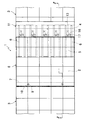
図1ないし図7に示す本発明を実施するための最良の第1の形態において、1は目地部2を介して設けられた左右の床躯体3、3間を覆う本発明の床用目地装置で、この床用目地装置1は前記左右の床躯体3、3の一方の床躯体3の目地部側の反目地部側が傾斜面4に形成された凹部5と、この凹部5内に所定間隔で固定され上部を除く部位にモルタルが充填される左右方向の複数個のガイド部材6と、前記凹部5内に先端部が位置してスライド移動可能に支持され、該先端部が上下方向に回動可能に後端部が前記他方の床躯体3の目地部側に固定された支持金具7に支持された目地プレート8と、この目地プレート8の後端部の底面に下方へ突出するように固定された、前記支持金具7に形成された透孔9、9にそれぞれ遊挿される複数個の支持ピン10、10と、前記目地プレート8の先端部に先端部が上下方向に回動するように枢支された、通常時には前記凹部5の先端部を覆う端部目地プレート11と、この端部目地プレート11の底面に所定間隔で固定された、該端部目地プレート11の撓みを防止するとともに、前記目地プレート8の先端部が前記一方の床躯体3の床面上に乗り上げる場合、端部目地プレート8の先端部が一方の床躯体3の床面と当接することなく案内する、前記目地プレート8の先端部と当接するストッパー部12を有する複数個のガイド片13とで構成されている。
1 to FIG. 7, in the first preferred embodiment for carrying out the present invention,
前記端部目地プレート11は該端部目地プレート11の後端部寄りの底面に所定間隔で固定された、前記複数個のガイド片13に形成された軸挿入孔14と、この複数個のガイド片13に沿うように前記目地プレート8の先端部に固定された、前記軸挿入孔14と一致する部位に軸挿入孔15が形成された軸受部材16と、この軸受部材16の軸挿入孔15と前記複数個のガイド片13の軸挿入孔14に挿入された枢支軸17とで先端部が上下方向に回動するように取付けられている。
The
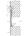
上記構成の床用目地装置1は、通常時には目地部2および一方の床躯体3に形成された凹部5は目地プレート8および端部目地プレート11で覆われた状態となっている。
この時、端部目地プレート11に大きな荷重が加わっても、該端部目地プレート11の底面に固定された複数個のガイド片13によって、その荷重を支持して撓んだりするのを防止する。
In the
At this time, even when a large load is applied to the
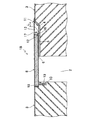
地震等によって、左右の床躯体3、3が凹部5の傾斜面4と複数個のガイド片13との間の隙L分の左右方向の揺れ動き時には、該隙間L分だけ端部目地プレート11が一方の床躯体3の床面と重なり合っているため、目地プレーと8および端部目地プレート11の左右方向のスライド移動によって、その揺れ動きを吸収する。
When the left and
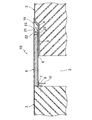
左右の床躯体3、3が大きく揺れ動き目地部2が狭くなると、図6に示すように端部目地プレート11および目地プレート8の先端部が一方の床躯体3の床面上に乗り上がり、該床面上をスライド移動するが、端部目地プレート11は複数個のガイド片13のストッパー部12が目地プレート8の先端部と当接して、先端部が床面と当接することがなく、該端部目地プレート11の先端部で床面を損傷させる不具合を確実に防止することができる。
When the left and
また、目地部2が広くなった場合も同様に、目地プレート8の先端部および端部目地プレート11の先端部が、図7に示すように凹部5内に位置するが、端部目地プレート11の先端部は凹部5の底面に当接することがないため、元の位置へ戻る時に従来のように傾斜面の端部の隅部と当接することなく端部目地プレート11が傾斜面4とだけ当接してスムーズにスライド移動させることができる。
[発明を実施するための異なる形態]
Similarly, when the
[Different forms for carrying out the invention]
次に、図8ないし図16に示す本発明を実施するための異なる形態につき説明する。なお、これらの本発明を実施するための異なる形態の説明に当って、前記本発明を実施するための最良の第1の形態と同一構成部分には同一符号を付して重複する説明を省略する。 Next, different modes for carrying out the present invention shown in FIGS. 8 to 16 will be described. In the description of these different modes for carrying out the present invention, the same components as those in the best mode for carrying out the present invention are designated by the same reference numerals and redundant description is omitted. To do.
図8および図9に示す本発明を実施するための第2の形態において、前記本発明を実施するための最良の第1の形態と主に異なる点は、他方の床躯体3の目地部側に目地プレート8の後端部を支持する支持凹部18と、該支持凹部18に形成した目地プレート8の後端部の底面に突出する複数個の支持ピン10、10が遊挿される支持ピン挿入穴19、19を形成するとともに、傾斜面4とガイド片13との間の隙間を上部より下部側が広くなるように設定した点で、このようにに構成した床用目地装置1Aにしても、前記本発明を実施するための最良の第1の形態と同様な作用効果が得られる。
The second embodiment for carrying out the present invention shown in FIG. 8 and FIG. 9 is mainly different from the best first embodiment for carrying out the present invention, in that the joint portion side of the other floor frame 3 A support recess 18 for supporting the rear end portion of the
図10ないし図13に示す本発明を実施するための第3の形態において、前記本発明を実施するための最良の第1の形態と主に異なる点は、端部目地プレート11を目地プレート8の先端部に固定された軸受部材20、20と、端部目地プレート11の床面に固定された軸受部材21、21とを枢支ピン22、22で枢支したヒンジ部材23、23を用いて取付けた点で、このように構成した床用目地装置1Bにしても、前記本発明を実施するための最良の第1の形態と同様な作用効果が得られる。
The third embodiment for carrying out the present invention shown in FIGS. 10 to 13 is mainly different from the best first embodiment for carrying out the present invention in that the
図14ないし図16に示す本発明を実施するための第4の形態において、前記本発明を実施するための最良の第1の形態と主に異なる点は、左右の床躯体3、3の目地部側に左右の凹部5、5を形成し、両端部が前記左右の凹部5、5に支持される目地プレート8Aの中央部が上下移動可能で、かつ常時目地部2の中央部に位置させることができるパンタグラフ形状の、少なくとも2個以上の中央維持機構24、24で支持し、目地プレート8Aの両端部に左右の端部目地プレート11、11を設けた点で、このように構成した床用目地装置1Cにしても、前記本発明を実施するための最良の第1の形態と同様な作用効果が得られる。
なお、本発明を実施するための形態ではパンタグラフ形状の中央維持機構を用いるものについて説明したが、本発明はこれに限らず、一対のレールと該一対のレールに両端部が係合される支持バーを用いた中央維持機構、四角枠形状のリンクを用いた中央維持機構、一対のラックとピニオンを用いた中央維持機構等、どんな機構の中央維持機構を用いてもよい。
また、左右の端部目地プレート11、11の取付けは前記本発明を実施するための第3の形態で使用したものを使用してもよい。
The fourth embodiment for carrying out the present invention shown in FIGS. 14 to 16 mainly differs from the best first embodiment for carrying out the present invention in that the joints of the left and
In the embodiment for carrying out the present invention, the one using the pantograph-shaped central maintenance mechanism has been described. However, the present invention is not limited to this, and a support in which both ends are engaged with the pair of rails is also provided. A central maintenance mechanism using a bar, a central maintenance mechanism using a square frame link, a central maintenance mechanism using a pair of racks and a pinion, etc. may be used.
The left and right end
本発明は床用目地装置を製造する産業で利用される。 The present invention is used in the industry for manufacturing floor joint devices.
1、 、1A、1B、1C:床用目地装置、
2:目地部、 3:床躯体、
4:傾斜面、 5:凹部、
6:ガイド部材、 7:支持金具、
8、8A:目地プレート、 9:透孔、
10:支持ピン、 11:端部目地プレート、
12:ストッパー部、 13:ガイド片、
14:軸挿入孔、 15:軸挿入孔、
16:軸受部材、 17:枢支軸、
L:隙間、 18:支持凹部、
19:支持ピン挿入穴、 20:軸受部材、
21:軸受部材、 22:枢支ピン、
23:ヒンジ部材、 24:中央維持機構。
1, 1A, 1B, 1C: floor joint device,
2: joint part, 3: floor frame,
4: Inclined surface, 5: Recess,
6: guide member, 7: support bracket,
8, 8A: Joint plate, 9: Through hole,
10: Support pin, 11: End joint plate,
12: stopper part, 13: guide piece,
14: shaft insertion hole, 15: shaft insertion hole,
16: bearing member, 17: pivot shaft,
L: gap, 18: support recess,
19: support pin insertion hole, 20: bearing member,
21: bearing member, 22: pivot pin,
23: Hinge member, 24: Central maintenance mechanism.
Claims (2)
Priority Applications (1)
| Application Number | Priority Date | Filing Date | Title |
|---|---|---|---|
| JP2005196317A JP4467474B2 (en) | 2005-07-05 | 2005-07-05 | Floor joint device |
Applications Claiming Priority (1)
| Application Number | Priority Date | Filing Date | Title |
|---|---|---|---|
| JP2005196317A JP4467474B2 (en) | 2005-07-05 | 2005-07-05 | Floor joint device |
Publications (2)
| Publication Number | Publication Date |
|---|---|
| JP2007016401A JP2007016401A (en) | 2007-01-25 |
| JP4467474B2 true JP4467474B2 (en) | 2010-05-26 |
Family
ID=37753800
Family Applications (1)
| Application Number | Title | Priority Date | Filing Date |
|---|---|---|---|
| JP2005196317A Active JP4467474B2 (en) | 2005-07-05 | 2005-07-05 | Floor joint device |
Country Status (1)
| Country | Link |
|---|---|
| JP (1) | JP4467474B2 (en) |
Families Citing this family (5)
| Publication number | Priority date | Publication date | Assignee | Title |
|---|---|---|---|---|
| JP4948236B2 (en) * | 2007-04-02 | 2012-06-06 | ドーエイ外装有限会社 | Floor joint device |
| JP2009299310A (en) * | 2008-06-11 | 2009-12-24 | Dooei Gaiso Kk | Floor joint device |
| JP2011084872A (en) * | 2009-10-13 | 2011-04-28 | Dooei Gaiso Kk | Joint device for floor |
| JP5278974B2 (en) * | 2010-07-29 | 2013-09-04 | ドーエイ外装有限会社 | Floor joint device |
| WO2015120993A2 (en) * | 2014-01-10 | 2015-08-20 | Seamus Devlin | A device for spanning an expansion joint in the floor of a building |
-
2005
- 2005-07-05 JP JP2005196317A patent/JP4467474B2/en active Active
Also Published As
| Publication number | Publication date |
|---|---|
| JP2007016401A (en) | 2007-01-25 |
Similar Documents
| Publication | Publication Date | Title |
|---|---|---|
| JP4467474B2 (en) | Floor joint device | |
| JP4813974B2 (en) | Floor joint device | |
| JP4273094B2 (en) | Floor joint device | |
| JP2018193824A (en) | Floor joint device | |
| JP5862971B2 (en) | Floor joint device | |
| JP4467476B2 (en) | Floor joint device | |
| JP4112567B2 (en) | Floor joint device | |
| JP2000240176A (en) | Ceiling joint cover device | |
| JP2015021361A (en) | Floor joint device | |
| JP4616191B2 (en) | Floor joint device | |
| JP2008255578A (en) | Joint device for floor | |
| JP4907614B2 (en) | Ceiling joint device | |
| JP4960334B2 (en) | Passage wall joint device | |
| JP3797610B2 (en) | Cross-joint floor joint equipment | |
| JP2010007287A (en) | Floor joint apparatus | |
| JP4021866B2 (en) | Floor joint device | |
| JP2018096145A (en) | Joint device for floor | |
| JP2012112187A (en) | Joint device for connecting passage | |
| JP6293202B2 (en) | Joint device | |
| JP5364752B2 (en) | Joint device | |
| JP5250588B2 (en) | Floor joint device | |
| JP4452227B2 (en) | Kasagi equipment | |
| JP4633677B2 (en) | Floor joint device | |
| JP6165823B2 (en) | Floor joint device | |
| JP4334513B2 (en) | Floor joint device |
Legal Events
| Date | Code | Title | Description |
|---|---|---|---|
| A621 | Written request for application examination |
Free format text: JAPANESE INTERMEDIATE CODE: A621 Effective date: 20070228 |
|
| A977 | Report on retrieval |
Free format text: JAPANESE INTERMEDIATE CODE: A971007 Effective date: 20090209 |
|
| A131 | Notification of reasons for refusal |
Free format text: JAPANESE INTERMEDIATE CODE: A131 Effective date: 20091013 |
|
| A521 | Written amendment |
Free format text: JAPANESE INTERMEDIATE CODE: A523 Effective date: 20091130 |
|
| TRDD | Decision of grant or rejection written | ||
| A01 | Written decision to grant a patent or to grant a registration (utility model) |
Free format text: JAPANESE INTERMEDIATE CODE: A01 Effective date: 20100202 |
|
| A01 | Written decision to grant a patent or to grant a registration (utility model) |
Free format text: JAPANESE INTERMEDIATE CODE: A01 |
|
| A61 | First payment of annual fees (during grant procedure) |
Free format text: JAPANESE INTERMEDIATE CODE: A61 Effective date: 20100223 |
|
| R150 | Certificate of patent or registration of utility model |
Ref document number: 4467474 Country of ref document: JP Free format text: JAPANESE INTERMEDIATE CODE: R150 Free format text: JAPANESE INTERMEDIATE CODE: R150 |
|
| FPAY | Renewal fee payment (event date is renewal date of database) |
Free format text: PAYMENT UNTIL: 20130305 Year of fee payment: 3 |
|
| FPAY | Renewal fee payment (event date is renewal date of database) |
Free format text: PAYMENT UNTIL: 20160305 Year of fee payment: 6 |
|
| R250 | Receipt of annual fees |
Free format text: JAPANESE INTERMEDIATE CODE: R250 |
|
| R250 | Receipt of annual fees |
Free format text: JAPANESE INTERMEDIATE CODE: R250 |
|
| R250 | Receipt of annual fees |
Free format text: JAPANESE INTERMEDIATE CODE: R250 |
|
| R250 | Receipt of annual fees |
Free format text: JAPANESE INTERMEDIATE CODE: R250 |