JP4616191B2 - Floor joint device - Google Patents
Floor joint device Download PDFInfo
- Publication number
- JP4616191B2 JP4616191B2 JP2006043601A JP2006043601A JP4616191B2 JP 4616191 B2 JP4616191 B2 JP 4616191B2 JP 2006043601 A JP2006043601 A JP 2006043601A JP 2006043601 A JP2006043601 A JP 2006043601A JP 4616191 B2 JP4616191 B2 JP 4616191B2
- Authority
- JP
- Japan
- Prior art keywords
- joint
- floor
- cover
- plate
- rear end
- Prior art date
- Legal status (The legal status is an assumption and is not a legal conclusion. Google has not performed a legal analysis and makes no representation as to the accuracy of the status listed.)
- Active
Links
Images


Description
本発明は目地部を介して設けられた床躯体間を覆う床用目地装置に関する。 The present invention relates to a floor joint device that covers a space between floor frames provided via joint portions.
従来、この種の床用目地装置は地震等の揺れ動きを吸収するため、左右の躯体間(クリアランス)の2倍が必要である。それ故に、例えばプラス、マイナス500ミリが必要な場合、本体の幅寸法は1000ミリ以上、実質1200ミリが必要となる。これは左右の躯体間が離間した場合には問題が生じないが、近接した場合、壁や柱があると1700ミリの壁や柱間の寸法が必須条件となり、それ以下の条件では設置することができないという欠点があった。
本発明は以上のような従来の欠点に鑑み、幅寸法が小さくても大きな揺れ動きを目地部に隙間が生じることなく吸収することができる床用目地装置を提供することを目的としている。 An object of the present invention is to provide a floor joint device that can absorb a large swaying motion without causing a gap in the joint portion even in the case of a small width dimension.
本発明の前記ならびにそのほかの目的と新規な特徴は次の説明を添付図面と照らし合わせて読むと、より完全に明らかになるであろう。
ただし、図面はもっぱら解説のためのものであって、本発明の技術的範囲を限定するものではない。
The above and other objects and novel features of the present invention will become more fully apparent when the following description is read in conjunction with the accompanying drawings.
However, the drawings are for explanation only and do not limit the technical scope of the present invention.
上記目的を達成するために、本発明は目地部を介した一方の目地部側の床躯体に、後端部が他方の目地部側の床躯体側に突出する先端部が水平方向に回動可能に取付けられた少なくとも2個以上の長方形状の板状のブラケットと、この少なくとも2個以上のブラケットの上面に支持されるとともに、該ブラケットの先端部に枢支された、ブラケット間の目地部を覆う目地カバーと、前記少なくとも2個以上のブラケットの先端部が、常時他方の目地部側の床躯体方向に付勢するブラケット付勢機構と、前記他方の目地部側の床躯体に後端部が取付けられた、前記目地カバー上をスライド移動できる先端部が前記一方の目地部側の床躯体に支持される目地プレートとで床用目地装置を構成している。 To achieve the above object, according to the present invention, a floor case on one joint part side through a joint part is rotated in a horizontal direction at a front end part whose rear end part projects to the floor case side on the other joint part side. At least two or more rectangular plate-like brackets that can be attached , and a joint portion between the brackets that is supported by the upper surface of the at least two or more brackets and pivotally supported at the tip of the brackets A joint cover that covers the joint, a bracket urging mechanism in which tip ends of the at least two brackets always urge toward the floor housing on the other joint portion side, and a rear end on the floor housing on the other joint portion side A joint device for a floor is constituted by a joint plate supported by a floor frame on the one joint portion side, with a tip portion to which a portion is attached and which can slide on the joint cover.
本発明は目地部を介した一方の床躯体の目地部側に形成された、反目地部側が傾斜面に形成された目地プレート支持凹部と、この目地プレート支持凹部に先端部が支持され、後端部が他方の目地部側の床躯体側に位置する目地カバーと、この目地カバーの後端部を回動可能で、かつ上下移動可能に先端部で支持することができる後端部が、前記一方の目地部側の床躯体に枢支された、上面で前記目地カバーを支持できる少なくとも2個以上の長方形状の板状のブラケットと、この少なくとも2個以上のブラケットあるいは前記目地カバーを常時前記他方の床躯体方向に付勢する付勢機構と、前記他方の目地部側の床躯体に後端部が上下移動可能に取付けられた、前記目地カバー上をスライド移動できる先端部が前記目地プレート支持凹部の傾斜面をスライド移動できる目地プレートとで床用目地装置を構成している。 In the present invention, a joint plate support concave portion formed on the joint portion side of one floor frame through the joint portion, the joint portion supporting side formed on an inclined surface, and a tip portion supported by the joint plate support concave portion, A joint cover whose end is located on the side of the floor joint on the other joint part side, and a rear end part that can be supported by the tip part so that the rear end part of this joint cover can be rotated and moved up and down, At least two or more rectangular plate-shaped brackets pivotally supported by the floor frame on the one joint portion side and capable of supporting the joint cover on the upper surface, and at least two or more brackets or the joint cover are always provided. An urging mechanism for urging in the direction of the other floor casing, and a tip end portion slidably movable on the joint cover, the rear end portion of which is attached to the floor casing on the other joint section side so as to be vertically movable is the joint. Tilt of plate support recess Constitute a floor joint device between joint plate surfaces can slide movement.
以上の説明から明らかなように、本発明にあっては次に列挙する効果が得られる。 As is clear from the above description, the present invention has the following effects.
(1)請求項1により、目地部が地震等で狭くなった場合には、目地カバーと目地プレートが一方の目地部側の床躯体上に侵入して、その揺れ動きを吸収するとともに、目地部が広くなった場合には、目地プレートの先端部が目地カバー上をスライド移動して、目地部に隙間が生じることなく、その揺れ動きを吸収することができる。
したがって、目地部の幅寸法がなくなる状態から、目地部の幅寸法が約2倍となる揺れ動きを吸収することができるとともに、目地部が狭くなっても、目地部の幅寸法分しか目地カバーと目地プレートが一方の目地部側の床躯体上に侵入することがなく、境界線や、壁や柱等が目地部の幅寸法分だけ目地部端部より離れていれば、安全に設置することができる。
よって、小型化、コンパクト化を図ることができるとともに、揺れ動きを安全に確実に吸収することができる。
(1) According to
Therefore, from the state where the width of the joint portion is eliminated, it is possible to absorb a swinging motion in which the width dimension of the joint portion is about twice, and even if the joint portion is narrowed, only the width dimension of the joint portion is Install the joint plate safely if the joint plate does not enter the floor frame on the side of the joint and the boundary line, wall, pillar, etc. are separated from the joint end by the width of the joint. Can do.
Therefore, it is possible to achieve downsizing and compactness, and it is possible to safely and reliably absorb the shaking motion.
(2)前記(1)によって、構造が簡単であるので、容易に設置することができる。 (2) According to the above (1), since the structure is simple, it can be easily installed.
(3)前記(1)によって、揺れ動きが停止すると、自動的に元の状態に戻すことができる。
したがって、地震のたびに点検することなく、安全に使用することができる。
(3) When the shaking motion is stopped by the above (1), the original state can be automatically restored.
Therefore, it can be used safely without checking every earthquake.
(4)請求項2も前記(1)〜(3) と同様な効果が得られるとともに、平常時には一方の床面と他方の床面と同一面に目地プレートの上面を位置させることができる。
(4) In
以下、図面に示す本発明を実施するための最良の形態により、本発明を詳細に説明する。 Hereinafter, the present invention will be described in detail with reference to the best mode for carrying out the invention shown in the drawings.
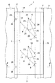
図1ないし図8に示す本発明を実施するための最良の第1の形態において、1は本発明の床用目地装置で、この床用目地装置1は目地部2を介した一方の床躯体3の目地部側に形成された、反目地部側が傾斜面4の目地プレート支持凹部5と、この目地プレート支持凹部5に後端部が支持され、先端部が他方の目地部側の床躯体6側に位置する目地カバー7と、この目地カバー7の先端部を回動可能で、かつ上下移動可能に先端部で支持することができる後端部が、前記一方の目地部側の床躯体3に水平方向に回動可能に枢支金具8で枢支された少なくとも2個以上のブラケット9、9と、この少なくとも2個以上のブラケット9、9あるいは前記目地カバー7を、常時前記他方の床躯体6方向に付勢する付勢機構10と、前記他方の目地部側の床躯体6に形成された目地プレート支持部11に後端部が上下移動可能に取付けられた、前記目地カバー7上をスライド移動できる目地プレート12とで構成されている。
In the first preferred embodiment for carrying out the present invention shown in FIGS. 1 to 8,
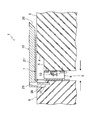
前記少なくとも2個以上のブラケット9、9は図3に示すように、長方形状の板状のブラケット本体13と、このブラケット本体13の後端部の上下部に取付けられた、前記一方の目地部側の床躯体3に複数本のタッピングビス14等で固定される、枢支金具8としてのヒンジ部材15、15と、前記ブラケット本体13の先端部の上下部位に固定された、前記目地カバー7の後部寄りの底面に取付けられた該目地カバー7を上方に押し圧するコイルスプリング16を介装した押し上げ棒17をガイドするとともに、下端部を係止するガイドパイプ18および係止パイプ19と、前記ブラケット本体13が目地部が狭くなった場合に、他方の目地部側の床躯体6でスムーズに回動できるように傾斜状態で停止させるストッパー20とで構成されている。
As shown in FIG. 3, the at least two
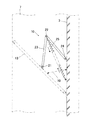
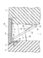
前記付勢機構10は図4に示すように、前記ブラケット本体13のほぼ中央部に固定された一方の枢支ピン21と、この一方の枢支ピン21に一端部が枢支された中央部が回動可能に中央枢支ピン22で枢支されたリンク23と、このリンク23の他端部を枢支する前記一方の目地部側の床躯体3に固定された他方の枢支ピン24と、前記リンク23の中央部寄りの部位あるいは中央枢支ピン22に一端部が取付けられ、他端部が前記一方の目地部側の床躯体3に固定された、前記リンク23を常時直線状態になるように付勢するコイルスプリング25とで構成されている。
As shown in FIG. 4, the
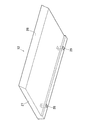
前記目地プレート12は図6に示すように、先端部が前記目地プレート支持凹部5の傾斜面4に面接触するように傾斜面26に形成された目地プレート本体27と、この目地プレート本体27の後端部寄りの底面に形成された、前記目地プレート支持部11に固定された支持ピン28、28が遊挿状態で入り込む支持ピン挿入孔29、29とで構成されている。
As shown in FIG. 6, the
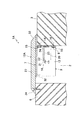
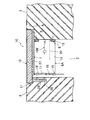
上記構成の床用目地装置1は通常時には図2に示すように、目地部2を一方の床躯体3の底面と他方の床躯体6の底面とがほぼ同一となるように目地プレート12で覆った状態になっている。
このとき、目地カバー7はコイルスプリング16で上方に押し上げられている押し上げ棒17によって、目地プレート12を押し上げることなく目地プレート12に密着した状態になっている。
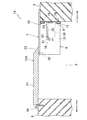
地震等で目地部2が広くなると、図7に示すように他方の床躯体6が一方の床躯体3より離れた状態となるため、目地プレート12が目地カバー7上をスライド移動して、通常時の目地部の幅寸法のほぼ2倍になるまで移動しても、目地部2を目地プレート12と目地カバー7で覆って、隙間が生じることなく目地部を覆うことができる。
また、地震等で目地部2が狭くなると、図8に示すように他方の床躯体6が一方の床躯体3に接近する状態となるため、他方の床躯体6によって目地カバー7および目地プレート12が一方の床躯体3上へ乗り上げ、ブラケット9、9が最小の収納状態となるまでスライド移動するが、一方の床躯体3上へ乗り上げられる目地カバー7および目地プレート12は、最大でも目地部2の幅寸法分だけ乗り上げるため、乗り上げ寸法を小さくできる。この場合、目地カバー7の後端部および目地プレート12の後端部は上方へ移動する。
As shown in FIG. 2, the
At this time, the
When the
Further, when the
なお、目地部2が狭くなった場合には、目地カバー7の後端部が少なくとも2個以上のブラケット9、9の回動によって前後方向に回動するが、前後方向に余分なスペースがある所では十分に使用することができる。
また、目地カバー7のほぼ中央部の底面に凹状のガイドレール30を設け、このガイドレール30と係合するピン31を目地プレート支持凹部5に設けることにより、目地カバー7の先端部寄りの位置を規制した状態で移動させることができる。
[発明を実施するための異なる形態]
When the
Further, a concave guide rail 30 is provided on the bottom surface of the substantially central portion of the
[Different forms for carrying out the invention]
次に、図9ないし図25に示す本発明を実施するための異なる形態につき説明する。なお、これらの本発明を実施するための異なる形態の説明に当って、前記本発明を実施するための最良の第1の形態と同一構成部分には同一符号を付して重複する説明を省略する。 Next, different modes for carrying out the present invention shown in FIGS. 9 to 25 will be described. In the description of these different modes for carrying out the present invention, the same components as those in the best mode for carrying out the present invention are designated by the same reference numerals and redundant description is omitted. To do.
図9ないし図14に示す本発明を実施するための第2の形態において、前記本発明を実施するための最良の第1の形態と主に異なる点は、目地カバー7の先端部を一方の床躯体3の床面に支持させるとともに、後端部を少なくとも2個以上のブラケット9、9の先端部に枢支ピン32、32で枢支し、目地プレート12Aの後端部を他方の床躯体6の目地部側の床面に固定した点で、このように構成した床用目地装置1Aにしても、目地部を覆う目地プレート12Aが両方の床面より高くなるが、それ以外は前記本発明を実施するための最良の第1の形態と同様な作用効果が得られる。
なお、目地プレート12Aの両端部は下部が外方へ突出する傾斜面33、33に形成されている。
The second embodiment for carrying out the present invention shown in FIG. 9 to FIG. 14 is mainly different from the best first embodiment for carrying out the present invention in that the tip of the
Note that both end portions of the
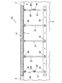
図15ないし図20に示す本発明者が考えた床用目地装置において、前記本発明を実施するための最良の第1の形態と主に異なる点は、一方の床躯体3の目地部側の床面より下部位置のほぼ水平方向に位置できるように固定された支持プレート34と、この支持プレート34に所定間隔で下端部が枢支ピン35で枢支され、先端部が枢支ピン36で目地カバー7の後端部の底面に枢支された複数個の支持バー37と、この複数個の支持バー37が必要以上に回動するのを阻止するストッパー用のワイヤー38とからなるブラケット9Aを用いた点で、このように構成した床用目地装置1Bにしてもよい。
なお、ブラケット9Aあるいは目地カバー7は目地部が狭くなって元の状態になった場合に、目地カバー7を元の状態に戻すため、複数個の支持バー37がストッパー用のワイヤー38で係止されるまで付勢できるように、支持バー37と一方の床躯体3間にスプリング39を介装したり、あるいは他方の床躯体6方向へ付勢するコイルスプリング40を用いた付勢機構10Aが用いられている。
In the floor joint device considered by the present inventor shown in FIGS. 15 to 20, the main difference from the first embodiment for carrying out the present invention is that the floor side of the
The
図21ないし図25に示す本発明を実施するための第3の形態において、前記本発明を実施するための最良の第1の形態と主に異なる点は、少なくとも2個以上のブラケット9、9を一方の目地部側の床躯体3と該少なくとも2個以上のブラケット9、9のブラケット本体13、13のほぼ中央部との間に該ブラケット本体13、13を常時他方の目地部側の床躯体6方向に突出するように付勢する
スプリングを用いた付勢機構10Bと、ブラケット本体13、13を所定の傾斜状態で停止させるストッパー20を用いた点で、このように構成した床用目地装置1Cにしても、前記本発明を実施するための最良の第1の形態と同様な作用効果が得られる。
The third embodiment for carrying out the present invention shown in FIGS. 21 to 25 is mainly different from the best first embodiment for carrying out the present invention in that at least two
本発明は床用目地装置を製造する産業で利用される。 The present invention is used in the industry for manufacturing floor joint devices.
1、 、1A、1B:床用目地装置、2:目地部、
3:一方の床躯体、 4:傾斜面、
5:目地プレート支持凹部、 6:他方の床躯体、
7:目地カバー、 8:枢支金具、
9、9A:ブラケット、 10、10A:付勢機構、
11:目地プレート支持部、 12:目地プレート、
13:ブラケット本体、 14:タッピングビス、
15:ヒンジ部材、 16:コイルスプリング、
17:押し上げ棒、 18:ガイドパイプ、
19:係止パイプ、 20:ストッパー、
21:一方の枢支ピン、 22:中央枢支ピン、
23:リンク、 24:他方の枢支ピン、
25:コイルスプリング、 26:傾斜面、
27:目地プレート本体、 28:支持ピン、
29:支持ピン挿入孔、 30:ガイドレール、
31:ピン、 32:枢支ピン、
33:傾斜面、 34:支持プレート、
35:枢支ピン、 36:枢支ピン、
37:支持バー、 38:ストッパー用ワイヤー、
39:スプリング、 40:コイルスプリング。
1, 1A, 1B: floor joint device, 2: joint portion,
3: One floor frame, 4: Inclined surface,
5: joint plate supporting recess, 6: other floor frame,
7: joint cover, 8: pivot bracket,
9, 9A: bracket, 10, 10A: biasing mechanism,
11: Joint plate support part, 12: Joint plate,
13: Bracket body, 14: Tapping screw,
15: Hinge member, 16: Coil spring,
17: Push-up rod, 18: Guide pipe,
19: Locking pipe, 20: Stopper,
21: One pivot pin, 22: Central pivot pin,
23: Link, 24: The other pivot pin,
25: Coil spring, 26: Inclined surface,
27: Joint plate body, 28: Support pin,
29: Support pin insertion hole, 30: Guide rail,
31: pin, 32: pivot pin,
33: inclined surface, 34: support plate,
35: pivot pin, 36: pivot pin,
37: Support bar, 38: Stopper wire,
39: Spring, 40: Coil spring.
Claims (2)
Priority Applications (1)
| Application Number | Priority Date | Filing Date | Title |
|---|---|---|---|
| JP2006043601A JP4616191B2 (en) | 2006-02-21 | 2006-02-21 | Floor joint device |
Applications Claiming Priority (1)
| Application Number | Priority Date | Filing Date | Title |
|---|---|---|---|
| JP2006043601A JP4616191B2 (en) | 2006-02-21 | 2006-02-21 | Floor joint device |
Publications (2)
| Publication Number | Publication Date |
|---|---|
| JP2007224502A JP2007224502A (en) | 2007-09-06 |
| JP4616191B2 true JP4616191B2 (en) | 2011-01-19 |
Family
ID=38546559
Family Applications (1)
| Application Number | Title | Priority Date | Filing Date |
|---|---|---|---|
| JP2006043601A Active JP4616191B2 (en) | 2006-02-21 | 2006-02-21 | Floor joint device |
Country Status (1)
| Country | Link |
|---|---|
| JP (1) | JP4616191B2 (en) |
Families Citing this family (4)
| Publication number | Priority date | Publication date | Assignee | Title |
|---|---|---|---|---|
| JP5931476B2 (en) * | 2012-02-03 | 2016-06-08 | ドーエイ外装有限会社 | Boundary joint device |
| JP5982171B2 (en) * | 2012-04-26 | 2016-08-31 | 第一機材株式会社 | Sliding seismic isolation joint cover device |
| JP6322515B2 (en) * | 2014-05-30 | 2018-05-09 | 株式会社Uacj金属加工 | Groove cover device |
| JP7433672B1 (en) | 2022-11-28 | 2024-02-20 | ドーエイ外装有限会社 | joint cover device |
Citations (2)
| Publication number | Priority date | Publication date | Assignee | Title |
|---|---|---|---|---|
| JP2004150231A (en) * | 2002-11-01 | 2004-05-27 | Abc Trading Co Ltd | Expansion joint |
| JP2005016173A (en) * | 2003-06-26 | 2005-01-20 | Dooei Gaiso Kk | Cover device for outer peripheral part of base-isolated building or the like |
-
2006
- 2006-02-21 JP JP2006043601A patent/JP4616191B2/en active Active
Patent Citations (2)
| Publication number | Priority date | Publication date | Assignee | Title |
|---|---|---|---|---|
| JP2004150231A (en) * | 2002-11-01 | 2004-05-27 | Abc Trading Co Ltd | Expansion joint |
| JP2005016173A (en) * | 2003-06-26 | 2005-01-20 | Dooei Gaiso Kk | Cover device for outer peripheral part of base-isolated building or the like |
Also Published As
| Publication number | Publication date |
|---|---|
| JP2007224502A (en) | 2007-09-06 |
Similar Documents
| Publication | Publication Date | Title |
|---|---|---|
| JP4616191B2 (en) | Floor joint device | |
| JP4273094B2 (en) | Floor joint device | |
| JP5862971B2 (en) | Floor joint device | |
| JP3122394B2 (en) | Joint railing wall | |
| JP4948236B2 (en) | Floor joint device | |
| JP2007016401A (en) | Floor joint unit | |
| JP6309075B1 (en) | Floor joint device | |
| JP5044609B2 (en) | Floor joint device | |
| JP4907614B2 (en) | Ceiling joint device | |
| JP4452227B2 (en) | Kasagi equipment | |
| JP4021870B2 (en) | Floor joint device | |
| JP6293202B2 (en) | Joint device | |
| JP5329591B2 (en) | Joint device | |
| JP5862963B2 (en) | Ceiling joint cover device | |
| JP5364752B2 (en) | Joint device | |
| JP5377947B2 (en) | Floor joint device | |
| JP2006265821A (en) | Joint device for wall surface | |
| JP5102264B2 (en) | Floor joint device | |
| JP5943896B2 (en) | Ceiling joint cover device | |
| JP5184485B2 (en) | Ceiling joint device | |
| JP4115970B2 (en) | Floor joint device | |
| JP2005163417A (en) | Joint device of connecting passageway | |
| JP6475878B1 (en) | Floor joint device | |
| JP4475589B2 (en) | Floor joint device | |
| JP6431758B2 (en) | Wall joint device |
Legal Events
| Date | Code | Title | Description |
|---|---|---|---|
| A621 | Written request for application examination |
Free format text: JAPANESE INTERMEDIATE CODE: A621 Effective date: 20071030 |
|
| A977 | Report on retrieval |
Free format text: JAPANESE INTERMEDIATE CODE: A971007 Effective date: 20100809 |
|
| A131 | Notification of reasons for refusal |
Free format text: JAPANESE INTERMEDIATE CODE: A131 Effective date: 20100824 |
|
| A521 | Request for written amendment filed |
Free format text: JAPANESE INTERMEDIATE CODE: A523 Effective date: 20100915 |
|
| TRDD | Decision of grant or rejection written | ||
| A01 | Written decision to grant a patent or to grant a registration (utility model) |
Free format text: JAPANESE INTERMEDIATE CODE: A01 Effective date: 20101012 |
|
| A01 | Written decision to grant a patent or to grant a registration (utility model) |
Free format text: JAPANESE INTERMEDIATE CODE: A01 |
|
| A61 | First payment of annual fees (during grant procedure) |
Free format text: JAPANESE INTERMEDIATE CODE: A61 Effective date: 20101021 |
|
| R150 | Certificate of patent or registration of utility model |
Ref document number: 4616191 Country of ref document: JP Free format text: JAPANESE INTERMEDIATE CODE: R150 Free format text: JAPANESE INTERMEDIATE CODE: R150 |
|
| FPAY | Renewal fee payment (event date is renewal date of database) |
Free format text: PAYMENT UNTIL: 20131029 Year of fee payment: 3 |
|
| R250 | Receipt of annual fees |
Free format text: JAPANESE INTERMEDIATE CODE: R250 |
|
| R250 | Receipt of annual fees |
Free format text: JAPANESE INTERMEDIATE CODE: R250 |
|
| R250 | Receipt of annual fees |
Free format text: JAPANESE INTERMEDIATE CODE: R250 |
|
| R250 | Receipt of annual fees |
Free format text: JAPANESE INTERMEDIATE CODE: R250 |