JP4467448B2 - Mobile recording device - Google Patents
Mobile recording device Download PDFInfo
- Publication number
- JP4467448B2 JP4467448B2 JP2005048753A JP2005048753A JP4467448B2 JP 4467448 B2 JP4467448 B2 JP 4467448B2 JP 2005048753 A JP2005048753 A JP 2005048753A JP 2005048753 A JP2005048753 A JP 2005048753A JP 4467448 B2 JP4467448 B2 JP 4467448B2
- Authority
- JP
- Japan
- Prior art keywords
- trigger
- image data
- recording
- unit
- signal
- Prior art date
- Legal status (The legal status is an assumption and is not a legal conclusion. Google has not performed a legal analysis and makes no representation as to the accuracy of the status listed.)
- Expired - Fee Related
Links
- 230000001133 acceleration Effects 0.000 claims description 47
- 238000012545 processing Methods 0.000 claims description 35
- 230000004044 response Effects 0.000 claims description 34
- 230000006854 communication Effects 0.000 claims description 28
- 238000004891 communication Methods 0.000 claims description 28
- 238000003384 imaging method Methods 0.000 claims description 21
- 230000007175 bidirectional communication Effects 0.000 claims description 7
- 230000000875 corresponding effect Effects 0.000 description 36
- 238000012217 deletion Methods 0.000 description 14
- 230000037430 deletion Effects 0.000 description 14
- 238000000034 method Methods 0.000 description 14
- 238000012544 monitoring process Methods 0.000 description 14
- 230000006835 compression Effects 0.000 description 10
- 238000007906 compression Methods 0.000 description 10
- 238000001514 detection method Methods 0.000 description 9
- 230000006870 function Effects 0.000 description 8
- 238000010586 diagram Methods 0.000 description 5
- 238000003825 pressing Methods 0.000 description 2
- 230000005540 biological transmission Effects 0.000 description 1
- 238000012937 correction Methods 0.000 description 1
- 230000002596 correlated effect Effects 0.000 description 1
- 230000000994 depressogenic effect Effects 0.000 description 1
- 238000009434 installation Methods 0.000 description 1
- 239000004973 liquid crystal related substance Substances 0.000 description 1
- 239000000463 material Substances 0.000 description 1
- 239000011159 matrix material Substances 0.000 description 1
- 230000001105 regulatory effect Effects 0.000 description 1
- 239000004065 semiconductor Substances 0.000 description 1
- 239000007787 solid Substances 0.000 description 1
- 238000012795 verification Methods 0.000 description 1
Images


Description
本発明は、車両等の移動体に取付けられる移動体用記録装置に関する。 The present invention relates to a moving body recording apparatus attached to a moving body such as a vehicle.
車両事故において、事故原因の事後的な検証のための客観的証拠を残すことを目的として、事故時点から数秒前までの状況を画像として記録しておく所謂ドライブレコーダ(ドライビングレコーダ)が提案されている。この種のドライブレコーダは、加速度センサによって衝撃発生の有無を検出し、これをトリガとして衝撃発生前後の画像を記録するようにしている。 In a vehicle accident, a so-called drive recorder (driving recorder) has been proposed that records the situation from the time of the accident as a few seconds before as an image for the purpose of leaving objective evidence for subsequent verification of the cause of the accident. Yes. This type of drive recorder detects the presence or absence of an impact by means of an acceleration sensor, and records images before and after the occurrence of the impact using this as a trigger.
一方において、駐車している車両の内部から物品等を盗難しようとする所謂車上あらしや車両に対するいたずら行為が問題となっており、これを防止又は抑制する技術としてセキュリティカメラ等が考えられる。この種のセキュリティカメラにおいては、動き検出などによって不審者の動きを検出し、不審者を撮影しようとする手法が用いられる。 On the other hand, so-called on-board sneaking attempts to steal goods and the like from inside a parked vehicle and a mischievous act on the vehicle are problematic, and a security camera or the like can be considered as a technique for preventing or suppressing this. In this type of security camera, a technique for detecting a suspicious person's movement by detecting a movement and photographing the suspicious person is used.
また、下記特許文献1には、映像記録媒体の特定部分にインデクス領域を設け、シヤッタースイッチの押下をきっかけとして映像データを該映像記録媒体に記録するとともに、該インデクス領域に、映像記録媒体内で実際の映像データが記録されている位置のアドレス、映像データ長、および該映像データの関連情報を記録するビデオカメラ装置の情報記録方法が開示されている。
Further, in
現在、ドライブレコーダとしての機能とセキュリティカメラとしての機能等、複数の機能を併せ持つ車載用記録装置は商品化されていない。こうした商品においては、機能の複数化に伴って記録する際のトリガとなる情報の多様化、記録情報の増加等が生じることが考えられる。また、特定のトリガに対応する情報のみを選択的に確認したり、削除したりする必要性も生じることが考えられる。 Currently, an in-vehicle recording apparatus having a plurality of functions such as a drive recorder function and a security camera function has not been commercialized. In such products, diversification of information that triggers recording, increase in recording information, and the like may occur due to a plurality of functions. In addition, it may be necessary to selectively check or delete only information corresponding to a specific trigger.
尚、上記特許文献1に記載の技術は、上述したようなトリガとなる情報の多様化等に対応できるものではない。
The technique described in
そこで本発明は、複数のトリガに応じて画像を記録するものでありながら、記録データの参照や管理が容易な移動体用記録装置を提供することを目的とする。 SUMMARY OF THE INVENTION An object of the present invention is to provide a mobile recording apparatus that can easily reference and manage recording data while recording an image in response to a plurality of triggers.
上記目的を達成するために本発明に係る移動体用記録装置は、移動体に取付けられる移動体用記録装置であって、撮像対象を撮影するための撮像部と、前記撮像部からの映像信号に応じた画像データを作成する信号処理部と、前記画像データを一時的に蓄積する第1の記録部と、与えられた入力信号に応じて複数種類のトリガを発生可能なトリガ発生部と、何れかの種類のトリガが発生したとき、そのトリガ発生時点を基準とした所定時点の画像データを含む動画像データを、前記第1の記録部の蓄積内容を参照しつつ記録する第2の記録部と、何れかの種類のトリガが発生したとき、そのトリガ発生時点を基準とした所定時点の画像データより所定サイズの静止画像データを作成する静止画像作成部と、発生したトリガの種類とそのトリガに応じて前記第2の記録部に記録された動画像データ及び静止画像データとを関連付けたリスト情報を作成するリスト情報作成部と、を備えたことを特徴とする。 In order to achieve the above object, a moving body recording apparatus according to the present invention is a moving body recording apparatus that is attached to a moving body, and includes an imaging section for capturing an imaging target, and a video signal from the imaging section. A signal processing unit for generating image data according to the first recording unit, a first recording unit for temporarily storing the image data, a trigger generation unit capable of generating a plurality of types of triggers according to a given input signal, Second recording that records moving image data including image data at a predetermined time with reference to the trigger generation time when any type of trigger occurs, with reference to the stored content of the first recording unit A still image creation unit that creates still image data of a predetermined size from image data at a predetermined time with reference to the trigger occurrence time, and the type of the generated trigger and its Trigger Depending characterized in that and a list information creation unit that creates a list information that associates the recorded moving image data and still image data in the second recording unit.
上記のようなリスト情報に基づけば、第2の記録部の記録内容をトリガの種類で分類したり、静止画像データをサムネイルとして用いて第2の記録部の記録内容を一覧表示したりすることが可能となる。このため、上記記録内容の参照や管理が容易となる。また、表示装置と接続するようにすれば、リスト情報に基づいた記録内容の一覧表示や記録内容のトリガの種類による分類表示等が可能となり、多機能でありながら操作性が極めて良い移動体用記録装置となる。 Based on the list information as described above, the recording contents of the second recording unit are classified according to the type of trigger, or the recorded contents of the second recording unit are displayed as a list using still image data as thumbnails. Is possible. For this reason, it becomes easy to refer to and manage the recorded contents. In addition, if connected to a display device, it is possible to display a list of recorded contents based on the list information, display classified according to the type of trigger of the recorded contents, etc. It becomes a recording device.
具体的には例えば、前記静止画像作成部は、何れかの種類のトリガが発生したとき、そのトリガ発生時点の所定時間前の画像データより前記静止画像データを作成する。 Specifically, for example, when any type of trigger occurs, the still image creation unit creates the still image data from image data of a predetermined time before the trigger occurrence time.
また例えば、前記入力信号には、前記移動体の加速度の大きさを特定する信号が含まれ、前記トリガ発生部は、前記加速度の大きさと1つ以上の閾値との比較結果に基づいてトリガを発生させるか否かと発生させるトリガの種類とを決定する。 Further, for example, the input signal includes a signal that specifies the magnitude of acceleration of the moving body, and the trigger generation unit triggers based on a comparison result between the magnitude of acceleration and one or more threshold values. Determine whether or not to generate and the type of trigger to generate.
また例えば、前記入力信号には、前記第2の記録部による前記動画像データの記録を要求する外部からの信号が含まれ、前記トリガ発生部は、その外部からの信号を受けたとき、その信号に対応した種類のトリガを発生させる。 Further, for example, the input signal includes an external signal that requests recording of the moving image data by the second recording unit, and the trigger generation unit receives the signal from the outside, Generate the type of trigger corresponding to the signal.
また例えば、他の移動体用記録装置との間で双方向通信を行うための通信回路を更に備え、前記入力信号には、前記通信回路を介して受信した他の移動体用記録装置からの所定の要求信号が含まれ、前記トリガ発生部は、前記通信回路を介して前記要求信号を受信したとき、その受信に対応した種類のトリガを発生させる。 Further, for example, a communication circuit for performing bidirectional communication with another mobile recording device is further provided, and the input signal is received from the other mobile recording device received via the communication circuit. When a predetermined request signal is included and the trigger generation unit receives the request signal via the communication circuit, the trigger generation unit generates a trigger of a type corresponding to the reception.
また例えば、前記入力信号には、外部からの操作によって生じる操作信号が含まれ、前記トリガ発生部は、前記操作信号を受けたとき、その操作信号に対応した種類のトリガを発生させる。 Further, for example, the input signal includes an operation signal generated by an external operation, and the trigger generation unit generates a trigger of a type corresponding to the operation signal when receiving the operation signal.
また例えば、前記入力信号には、前記移動体の加速度の大きさを特定する信号が含まれ、前記複数種類のトリガとは、第1のトリガ、第2のトリガ、・・・、第nのトリガ(nは2以上の整数)であり、前記加速度の大きさが所定の第1の閾値以上に達したとき、前記トリガ発生部は第1のトリガを発生させ、且つ前記第2の記録部は、そのトリガ発生時点の所定時間前の画像データを含む動画像データを記録する。 Further, for example, the input signal includes a signal that specifies the magnitude of acceleration of the moving body, and the plurality of types of triggers include a first trigger, a second trigger,. A trigger (n is an integer equal to or greater than 2), and when the magnitude of the acceleration reaches a predetermined first threshold value or more, the trigger generation unit generates a first trigger, and the second recording unit Records moving image data including image data a predetermined time before the trigger occurrence time.
また例えば、前記移動体の駐停車時において前記加速度の大きさが前記第1の閾値より小さい所定の第2の閾値以上に達したとき、前記トリガ発生部は第2のトリガを発生させ、且つ前記第2の記録部は、そのトリガ発生時点の所定時間前の画像データ及びその時点以降の画像データの内の少なくとも一方の画像データを含む動画像データを記録する。 Also, for example, when the magnitude of the acceleration reaches or exceeds a predetermined second threshold value smaller than the first threshold value when the moving body is parked or stopped, the trigger generation unit generates a second trigger, and The second recording unit records moving image data including at least one of image data of a predetermined time before the trigger occurrence time and image data after that time.
また例えば、前記信号処理部は、前記第1のトリガの発生時に前記第2の記録部が記録すべき動画像データに暗号処理を施す。 For example, the signal processing unit performs encryption processing on the moving image data to be recorded by the second recording unit when the first trigger is generated.
第1のトリガの発生時に前記第2の記録部に記録される動画像データは、車両事故の原因究明のために必要となる証拠資料等になりうるが、上記のように暗号処理を施すことにより動画像データの改ざん等が防止される。 The moving image data recorded in the second recording unit when the first trigger is generated can be evidence material or the like necessary for investigating the cause of the vehicle accident, but is subjected to encryption processing as described above. As a result, falsification of moving image data is prevented.
また例えば、前記静止画像データ及び前記リスト情報は前記第2の記録部に記録され、当該移動体用記録装置は、外部の表示装置と有線或いは無線にて接続するための接続手段と、前記第2の記録部の記録内容の一覧表示要求を受け付けるとともに、一覧表示要求を受けたとき、前記リスト情報に基づきつつ前記表示装置に前記記録内容を項目で区分けして一覧表示させる一覧表示制御手段と、を更に備えるようにしてもよい。 Further, for example, the still image data and the list information are recorded in the second recording unit, and the mobile recording device includes a connection unit for connecting to an external display device by wire or wirelessly, A list display control means for receiving a list display request for recording contents of the two recording units and displaying the list by dividing the recording contents into items on the display device based on the list information when receiving the list display request; , May be further provided.
また例えば、前記一覧表示制御手段によって表示された一覧表示に含まれる項目の選択を受け付ける選択受付手段と、前記リスト情報に基づきつつ選択された項目に対応する動画像データを再生映像として前記表示装置に表示させる項目表示制御手段と、を更に備えるようにしてもよい。 Also, for example, a selection receiving unit that receives selection of an item included in the list display displayed by the list display control unit, and the display device using the moving image data corresponding to the item selected based on the list information as a playback video And an item display control means to be displayed.
従来の移動体用記録装置において記録された画像データは、事故発生時にのみ確認される性質のものであるため、使用者が記録内容を確認することができない。しかしながら、上記のように構成すれば、第2の記録部の記録内容を一覧表示にて確認したり、動画像として確認したりすることが可能となる。 Since the image data recorded in the conventional moving body recording device is of a property that can be confirmed only when an accident occurs, the user cannot confirm the recorded contents. However, if configured as described above, the recorded contents of the second recording unit can be confirmed in a list display or confirmed as a moving image.
また例えば、前記一覧表示制御手段によって表示された一覧表示に含まれる項目の選択を受け付ける選択受付手段と、前記リスト情報に基づきつつ選択された項目に対応する動画像データを前記第2の記録部から消去する項目消去制御手段と、を更に備えるようにしてもよい。 Also, for example, selection accepting means for accepting selection of an item included in the list display displayed by the list display control means, and moving image data corresponding to the item selected based on the list information is stored in the second recording unit. And an item deletion control means for deleting from.
これにより、不要なデータを使用者の判断で第2の記録部から消去することが可能となり、第2の記録部の記録領域が有効に利用される。 As a result, unnecessary data can be erased from the second recording unit at the discretion of the user, and the recording area of the second recording unit can be used effectively.
また例えば、前記移動体の主電源遮断時において特定の種類のトリガが発生した場合、前記一覧表示制御手段は、前記移動体の主電源が投入された際に、その特定の種類のトリガに対応する項目の一覧表示を前記表示装置に自動的に行わせる。 Also, for example, when a specific type of trigger occurs when the main power of the moving body is shut down, the list display control means responds to the specific type of trigger when the main power of the moving body is turned on. The display device automatically displays a list of items to be performed.
例えば、移動体の主電源を遮断していたときに、不審者が移動体内の物品の盗難を試みたり移動体に危害(振動)を加えたりした場合は、特定の種類のトリガが発生する(発生しうる)。上記一覧表示を行えば、このような事態が発生していたことを主電源投入時に容易に確認することができる。 For example, when a suspicious person attempts to steal an article in the moving body or harms (vibrates) the moving body while the main power source of the moving body is shut off, a specific type of trigger occurs ( Can occur). By performing the above list display, it is possible to easily confirm that such a situation has occurred when the main power is turned on.
また例えば、前記第2の記録部の空き容量が所定容量以下になり、且つ前記第2の記録部の記録内容中に特定の種類のトリガに応じて記録された動画像データがある場合、前記一覧表示制御手段は、その特定の種類のトリガに対応する項目の一覧表示とその動画像データの消去要請に関する報知を前記表示装置に自動的に行わせる。 Also, for example, when the free space of the second recording unit is equal to or less than a predetermined capacity and there is moving image data recorded in response to a specific type of trigger in the recording content of the second recording unit, The list display control means automatically causes the display device to perform a list display of items corresponding to the specific type of trigger and a notification regarding a request to delete the moving image data.
上記のような一覧表示と報知を行うことで、例えば重要度の比較的低い記録データが第2の記録部から消去されるようになる(消去される方向に向かう)。これにより、第2の記録部の記録領域が有効に利用される。 By performing the list display and notification as described above, for example, recording data having a relatively low importance level is erased from the second recording unit (toward the erasing direction). Thereby, the recording area of the second recording unit is effectively used.
また例えば、特定の種類のトリガに応じて前記第2の記録部に記録された動画像データの消去は禁止されている。 Further, for example, erasure of moving image data recorded in the second recording unit in accordance with a specific type of trigger is prohibited.
第2の記録部に記録された動画像データの中には、車両事故の原因究明のために必要な映像が含まれる場合もある。このような動画像データに上記特定の種類のトリガを割り当てるようにすれば、消去が禁止される。つまり、上記のように構成すれば、消去を禁止すべき動画像データとそうでない動画像データとをトリガの種類で分類できるようになる。 The moving image data recorded in the second recording unit may include video necessary for investigating the cause of the vehicle accident. If the specific type of trigger is assigned to such moving image data, erasure is prohibited. In other words, if configured as described above, it is possible to classify the moving image data that should not be erased and the moving image data that is not prohibited by the type of trigger.
また例えば、前記移動体の主電源遮断時において特定の種類のトリガが発生した場合、前記移動体の主電源が投入された際に、その発生を知らせる報知を外部の表示装置に自動的に行わせる報知手段を更に備えるようにしてもよい。 In addition, for example, when a specific type of trigger occurs when the main power of the moving body is cut off, when the main power of the moving body is turned on, a notification notifying the occurrence is automatically given to an external display device. You may make it provide further the alerting | reporting means to make.
また例えば、前記第2の記録部の空き容量が所定容量以下になり、且つ前記第2の記録部の記録内容中に特定の種類のトリガに応じて記録された動画像データがある場合、その動画像データの消去要請に関する報知を外部の表示装置に自動的に行わせる報知手段を更に備えるようにしてもよい。 Further, for example, when the free capacity of the second recording unit is equal to or less than a predetermined capacity and there is moving image data recorded in response to a specific type of trigger in the recording content of the second recording unit, You may make it further provide the alerting | reporting means which makes the external display apparatus automatically alert | report regarding the deletion request | requirement of moving image data.
上述した通り、本発明に係る移動体用記録装置は、複数のトリガに応じて画像を記録するものでありながら、記録データの参照や管理が容易である。 As described above, the moving body recording apparatus according to the present invention records an image in response to a plurality of triggers, and can easily refer to and manage recording data.
以下、本発明に係る移動体用記録装置(ドライブレコーダ)の実施形態につき、図面に沿って具体的に説明する。図1は、本実施形態に係るドライブレコーダ1の構成を示すブロック図である。
DESCRIPTION OF THE PREFERRED EMBODIMENTS Embodiments of a moving body recording apparatus (drive recorder) according to the present invention will be specifically described below with reference to the drawings. FIG. 1 is a block diagram showing the configuration of the
図1のドライブレコーダ1は、撮像部2、信号処理部3、バッファメモリ(第1の記録部)4、記録部(第2の記録部)5、トリガ発生部6、静止画像作成部7、リスト情報作成部8、主制御部10及び接続部16を有して構成される。表示装置14は、車両に備えられたカーナビゲーションシステム等を構成する液晶ディスプレイ等の表示装置であり、ドライブレコーダ1の各部位との間で情報のやり取りが可能となるように接続部16を介してドライブレコーダ1と接続されている。
1 includes an
図1は、図面の煩雑化防止のため、表示装置14が接続部16を介して主制御部10に接続されている状態を示しているが、表示装置14は接続部16を介して接続が必要なドライブレコーダ1の各部位に接続される。表示装置14とドライブレコーダ1を有線にて接続する場合、接続部16はそれらを接続するための接続端子である。表示装置14とドライブレコーダ1を無線にて接続する場合、接続部16はそれらの間で双方向通信が可能なように構成された通信回路である。
FIG. 1 shows a state in which the
表示装置14には、使用者が表示装置14に必要な情報を与えるときに用いられる入力部15が設けられている。この入力部15は、例えばカーソルとボタンから構成されている。或いは、表示画面上のタッチパネルから構成されている。尚、表示装置14は、ドライブレコーダ1に備えられているものと考えても構わない。この場合、ドライブレコーダ1は表示装置14をも含んで構成されることになる。また、表示装置14を、ドライブレコーダ1の内部に組み込んでも構わない。また、表示装置14は、車両外部のコンピュータ等であっても構わない。この場合、インターネット網等の通信網を介してドライブレコーダ1と表示装置14は接続されることとなる。
The
ドライブレコーダ1は、自動車等の車両(不図示)に取付けられる。ドライブレコーダ1は、例えば、撮像部2が車両の前方(進行方向)にある撮像対象(風景)をフロントガラス(不図示)を介して撮像(撮影)できるように、車両のルームミラー(不図示)の裏側などに取付けられる。但し、車両におけるドライブレコーダ1の取付け場所は、ルームミラーに限られない。例えば、車両のルーフやサイドミラー(不図示)等に取付けてもよい。また、必要に応じて、車両の後方(進行方向と反対側)にある撮像対象(風景)を撮像できるように、車両の任意の箇所にドライブレコーダ1を取付けても良いし、車両内外のその他の方向の撮像対象(風景)を撮像できるように、車両の任意の箇所にドライブレコーダ1を取付けるようにしても良い。以下の説明において、単に「車両」と言った場合、それはドライブレコーダ1が上記のように取付けられた車両を指すものとする。
The
撮像部2は、ドライブレコーダ1の撮像対象を撮像(撮影)するためのものであり、例えば、撮像対象に応じた画像を映像信号(電気信号)に変換するCCD(Charge Coupled Devices)から構成される。このCCDは、例えば、毎秒30枚の画像を撮影する。即ち、フレーム周波数(フレームレート)は、例えば30枚/秒である。
The
信号処理部3は、カメラ2からの映像信号(カメラ2にて撮像された画像)を画像データに変換する。この際、カメラ2からの映像信号に画質補正などの適切な処理を施した上で画像データを作成してもよい。信号処理部3から出力される上記画像データは、バッファメモリ4に与えられる。また、その画像データは、場合によっては記録部5や静止画像作成部7にも与えられる。また、信号処理部3は、バッファメモリ4に記録されている画像データを記録部5や静止画像作成部7に供給する機能も併せ持つ。
The
バッファメモリ4は、信号処理部3から出力された画像データ(「動画像データ」とも言える)を一時的に蓄積(記憶)するDRAM(Dynamic Random Access Memory)等の半導体メモリである。このバッファメモリ4は、数秒〜数十秒間の画像データ(動画)を時系列に記憶することが可能である。バッファメモリ4の記憶内容は、ループ式に次々と新たな画像データに置き換えられる。即ち、記録容量を全て使い果たし、さらに追加して画像データを記憶することができなくなった時は、古い方の画像データから消去を行い、代わりに最新の画像データを記憶する(最も古くに記憶された画像データを、最新の画像データで上書きする)。
The
記録部5は、バッファメモリ4に記憶された画像データの一部を動画像データとして記録する他、後述する静止画像データ等も記録する。記録部5は、持ち運び可能なメモリカード等の記録媒体となっている。但し、それ単体では使用者が持ち運ぶことのできないようにドライブレコーダ1内に固定された記録媒体を、記録部5として採用してもよい。記録部5がどの時点(期間)の動画像データを記録するかは、主制御部10によって決定される。
The
トリガ発生部6は、入力信号源9から与えられた入力信号に応じて複数の種類のトリガ信号を発生するものである。図2は、トリガ発生部6と入力信号源9の内部構成を示す図である。図2において、図1と同一の部分には同一の符号を付す。入力信号源9としては、加速度センサ31、操作ボタン32、通信回路33などが挙げられる。トリガ発生部6は、比較部41、レベル判定部42、状態検出部43、信号判定部44及びトリガ生成判定部45を有して構成される。
The
加速度センサ31は、ドライブレコーダ1が取付けられた車両の加速度の大きさを検出する。加速度の大きさに加えて加速度の向きを検出するものであってもよい。尚、加速度センサ31は、ドライブレコーダ1に備えられているものであっても良いし、ドライブレコーダ1の外部に備えられているものであっても良い。例えば、加速度センサ31が車両に備えられている場合は、検出した加速度の大きさや向きを有線又は無線の通信を用いてドライブレコーダ1に伝達すればよい。以下、加速度センサ31によって検出された加速度の大きさを、加速度の大きさGと称することがある。
The
加速度センサ31によって検出された加速度の大きさGを特定する信号は、比較部41とレベル判定部42に与えられる。比較部41は、与えられた加速度の大きさGと所定の閾値THとを比較する。そして、比較部41は、加速度の大きさGがその閾値TH以上となっている場合にハイレベルの信号をトリガ生成判定部45に出力する一方、加速度の大きさGがその閾値TH未満の場合にローレベルの信号をトリガ生成判定部45に出力する。
A signal specifying the magnitude G of acceleration detected by the
レベル判定部42は、与えられた加速度の大きさGを第1の衝撃閾値TL1及び第2の衝撃閾値TL2の夫々と比較する(但し、TL1>TL2)。そして、G≧TL1が成立する場合に「2」を表す出力信号を、TL1>G≧TL2が成立する場合に「1」を表す出力信号を、G<TL2が成立する場合に「0」を表す出力信号を、トリガ生成判定部45に出力する。説明の具体化のため、加速度の大きさGとの比較に用いられる衝撃閾値を、第1の衝撃閾値TL1と第2の衝撃閾値TL2の2つとしたが、この衝撃閾値の個数は、1以上の任意の個数にすることができる。勿論、採用する衝撃閾値の個数に応じて、レベル判定部42の出力信号の種類は変化し、その種類は「(衝撃閾値の個数)+1」となる。
The
第1の衝撃閾値TL1は、車両の走行時に衝突事故等が発生したかを検出するための閾値であり、例えば、0.4×9.8m/s2に設定されている。第2の衝撃閾値TL2は、車両の停車時において車両に自転車等が当たったかどうかや、車両の駐車時において不審者が車両に振動等を与えたかどうか等を検出するための閾値であり、例えば、0.05×9.8m/s2〜0.1×9.8m/s2程度に設定される。また、比較部41において加速度の大きさGとの比較に用いられる上記閾値THは、車両の走行時においては第1の衝撃閾値TL1と等しいとされ、車両の駐停車時(停車時又は駐車時)には第2の衝撃閾値TL2と等しいとされる。
The first impact threshold value TL1 is a threshold value for detecting whether a collision accident or the like has occurred during travel of the vehicle, and is set to 0.4 × 9.8 m / s 2 , for example. The second impact threshold value TL2 is a threshold value for detecting whether or not a bicycle hits the vehicle when the vehicle is stopped or whether or not a suspicious person gives vibration or the like to the vehicle when the vehicle is parked. , 0.05 × 9.8 m / s 2 to 0.1 × 9.8 m / s 2 . Further, the threshold value TH used for comparison with the acceleration magnitude G in the
操作ボタン32は、ドライブレコーダ1自身或いは表示装置14等に設けられている操作ボタンであり、操作者(使用者)によって操作ボタンが押下げ(プッシュ)された場合に操作信号を状態検出部43に出力する。状態検出部43は、その操作ボタン32の状態を検出する。具体的には、状態検出部43は、操作ボタン32が押下げ(プッシュ)された場合に操作ボタン32から与えられる操作信号を受け、ハイレベルの信号をトリガ生成判定部45に出力する。一方、操作ボタン32が押下げされていない場合にはローレベルの信号をトリガ生成判定部45に出力する。操作ボタン32が表示装置14に設けられているものである場合、操作ボタン32の状態は接続部16を介して状態検出部43に伝達される。
The
通信回路33は、他のドライブレコーダ1との間で双方向通信を行うためのものである。詳細は後述するが、当該ドライブレコーダ1が取付けられた車両の加速度の大きさが衝突事故等に起因して第1の衝撃閾値TL1以上に達したとき、主制御部10は、通信回路33を介して他のドライブレコーダ1に画像データ(動画像データ)の記録を求める要求信号(後述する第1要求信号)を出力する。従って、逆に他のドライブレコーダ1から上記要求信号が送信されてくる場合がある。この要求信号を受けた場合、例えば、ドライブレコーダ1は自身の記録部5に要求信号を受けた前後の動画像データを記録させる。この記録された動画像データは、衝突事故等の原因検証用に用いることが可能となる。
The
信号判定部44は、上記のような要求信号を受信したか否かを判定する。信号判定部44は、要求信号を受信した場合はハイレベルの信号を、要求信号を受信していない場合はローレベルの信号をトリガ生成判定部45に出力する。
The
トリガ生成判定部45は、比較部41、状態検出部43及び信号判定部44からの出力信号の何れかがローレベルからハイレベルに切り換わった時にトリガ信号を主制御部10等に出力する。この際、このトリガ信号と併せてトリガ信号の種類を示すトリガ種類信号を主制御部10等に出力する。
The trigger
具体的には例えば、トリガ信号の発生要因が比較部41からのハイレベルの出力信号であって且つレベル判定部42の出力信号が「2」の場合、トリガ種類信号は「G02」とされ、トリガ信号の発生要因が比較部41からのハイレベルの出力信号であって且つレベル判定部42の出力信号が「1」の場合、トリガ種類信号は「G01」とされる。トリガ種類信号を表す記号の内、頭文字の「G」はこのトリガ種類信号が加速度センサ31の出力に応じて出力されたものであることを表し、頭文字に続く数値(01や02)はレベル判定部42の出力信号値を反映したものである。
Specifically, for example, when the generation factor of the trigger signal is a high level output signal from the
また、トリガ信号の発生要因が状態検出部43からのハイレベルの出力信号である場合、トリガ種類信号は「B00」とされる。トリガ種類信号を表す記号の内、頭文字の「B」はこのトリガ種類信号が操作ボタン32の出力に応じて出力されたものであることを表している。頭文字「B」に続く数値は固定値(00)であるとして説明するが、操作ボタン32の数又は操作ボタン32からの操作信号の種類の数に応じて、頭文字「B」に続く数値の種類を増加させてもよい。例えば、操作ボタン32を2つ設け(不図示)、各操作ボタン32に対する操作(押下げ)にトリガ種類信号「B00」、「B01」を割り付けるようにしてもよい。この場合、状態検出部43は、ローレベルとハイレベルの二値化信号だけでなく、操作ボタン32の数又は操作ボタン32からの操作信号の種類の数に応じた種類の出力信号をトリガ生成判定部45に伝達するようにすればよい。
When the trigger signal is generated by the high-level output signal from the
また、トリガ信号の発生要因が信号判定部44からのハイレベルの出力信号である場合、トリガ種類信号は「C00」とされる。トリガ種類信号を表す記号の内、頭文字の「C」はこのトリガ種類信号が通信回路33の受信信号に応じて出力されたものであることを表している。頭文字「C」に続く数値は固定値(00)であるとして説明するが、ドライブレコーダ1に画像データ(動画像データ)の記録を求める要求信号の種類の数に応じて、頭文字「C」に続く数値の種類を増加させてもよい。例えば、他のドライブレコーダ1から送信されてくる「画像データ(動画像データ)の記録を求める要求信号」が2種類ある場合は、夫々にトリガ種類信号「B00」、「B01」を割り付けるようにすればよい。この場合、信号判定部44は、ローレベルとハイレベルの二値化信号だけでなく、上記要求信号の種類の数に応じた種類の出力信号をトリガ生成判定部45に伝達するようにすればよい。
When the trigger signal is generated by a high-level output signal from the
また、他のドライブレコーダ1との間での双方向通信を実現することに加えて、インターネット網等の通信網を介して外部のコンピュータ(不図示)等と通信が可能となるように通信回路33を構成してもよい。この場合、そのようなコンピュータが送信した「ドライブレコーダ1の記録部5による画像データ(動画像データ)の記録等を求める要求信号」を受信したとき、信号判定部44にハイレベルの出力信号をさせると共に、トリガ生成判定部45に他と異なるトリガ種類信号(例えば「B02」)を出力させればよい。
In addition to realizing bidirectional communication with
また、更に上記要求信号を表示装置14が発信するようにしてもよい。この場合における通信回路33は接続部16と一致する。そして、表示装置14から送信されてくる上記要求信号を受けたとき、信号判定部44にハイレベルの出力信号をさせると共に、トリガ生成判定部45に他と異なるトリガ種類信号(例えば「B03」)を出力させればよい。
Further, the
トリガ生成判定部45が出力するトリガ信号とトリガ種類信号を併せて考えれば、トリガ生成判定部45は、互いに区別される複数種類のトリガを発生するものであると言える。以下の説明において、トリガ種類信号が「G01」、「G02」、「B00」、「C00」のトリガ信号を、それぞれ監視トリガ、衝突トリガ、操作トリガ、要求トリガと呼び、それらを統括してトリガと呼ぶ。
Considering together the trigger signal output from the trigger
主制御部10は、トリガの発生に応じて記録部5による動画像データの記録動作を制御すると共に、ドライブレコーダ1の各部の動作を統括的に制御する。また、主制御部10には、GPS(Global Positioning System)11から与えられる位置情報、時計装置12から与えられる時刻情報(日付含む)及び速度センサ13から与えられる車両の速度を特定する速度情報などが、与えられている。上記位置情報には、ドライブレコーダ1が取付けられている車両の現在地を特定する情報が含まれている。GPS11、時計装置12、速度センサ13は、ドライブレコーダ1に備えられているものであっても良いし、ドライブレコーダ1の外部に備えられているものであっても良い。それらがドライブレコーダ1の外部に備えられている場合、各情報(位置情報、時刻情報及び速度情報)は有線或いは無線にてドライブレコーダ1に伝達される。典型的には、車両に備えられたカーナビゲーションシステム等に含まれているものをGPS11として利用すればよく、車両の速度を計測するために車両に予め備えられているものを速度センサ13として利用すればよい。
The
静止画像作成部7及びリスト情報作成部8は、トリガの発生に応じて動作するものであり、主制御部10等を含めたこれらの部位の動作を、以下に説明する。今、タイミングT1において何れかの種類のトリガ(衝突トリガ、監視トリガ、操作トリガ及び要求トリガの何れか)が発生したとする。
The still image creation unit 7 and the list information creation unit 8 operate in response to the occurrence of a trigger, and the operation of these parts including the
主制御部10は、そのトリガ発生時点(タイミングT1)を基準とした所定時点の画像データを含む動画像データが記録部5に記録されるよう、信号処理部3等を制御する。より具体記には、何れかの種類のトリガが発生し、そのトリガを受けたタイミングから所定期間が経過した後、主制御部10は、信号処理部3にバッファメモリ4への新たな記録停止とバッファメモリ4に記録されている画像データ(動画像データ)の読み出しと読み出した画像データ(動画像データ)の記録部5への出力を指示する。
The
この指示を受けてバッファメモリ4から画像データ(動画像データ)を読み出した信号処理部3は、その画像データに圧縮処理を施し、その圧縮処理後の画像データ(動画像データ)を記録部5の動画像記録領域5aに記録させる(図3参照)。尚、バッファメモリ4への画像データの書き込み時に、既に圧縮処理が行われている場合は、記録部5への書き込み時における圧縮処理は不要である。また、トリガ発生時点以降の画像データ(動画像データ)を記録部5に記録させる場合は、バッファメモリ4を介することなく直接記録部5に画像データ(動画像データ)を書き込んでも構わない。
Upon receiving this instruction, the
トリガ発生に応じて記録部5に記録される動画像データには、タイミングT1(例えば、衝突時)以前の所定時間、或いは、タイミングT1前後の所定時間の画像データが含まれている。即ち、タイミングT1の所定時間前からタイミングT1に至るまでの画像データから構成される動画像データ、或いは、タイミングT1の所定時間前からタイミングT1に至るまでの画像データとタイミングT1からタイミングT1の所定時間後に至るまでの画像データとで構成される動画像データが、記録部5の動画像記録領域5aに記録される。
The moving image data recorded in the
また、タイミングT1以降の画像データから構成される動画像データのみを記録部5に記録するようにしても構わない。例えば、省電力の観点から駐車時においては撮像部2への電源供給を遮断しておき、監視トリガが発生した時点で撮像部2への電力供給が再開されるようにドライブレコーダ1を構成することもできるが、その場合においては、不審者が車両に振動等を与えることにより「監視トリガ」がタイミングT1に発生したとしても、当然、タイミングT1より前の画像データを記録することはできない。このため、そのような場合は、タイミングT1以降の動画像データを記録部5に記録するようにすればよい。
Alternatively, only moving image data composed of image data after timing T1 may be recorded in the
記録部5の記録領域は、図3に示す如く、動画像記録領域5a、静止画像記録領域5b及びリスト情報記録領域5c(以下、それぞれ単に「領域a、領域b、領域c」という場合がある)とに分かれている。領域5a〜5cは、1つの記録媒体の中で分けられた領域であっても良いし、それぞれ物理的に分離した領域であってもよい。極端には、互いに異なる第1記録媒体、第2記録媒体及び第3記録媒体を用意し、領域5a、5b及び5cを、夫々第1、第2及び第3記録媒体に割り当てるようにしても良い。
As shown in FIG. 3, the recording area of the
静止画像作成部7は、主制御部10による制御を受けつつ、トリガ発生時点(タイミングT1)を基準とした所定時点の画像データを信号処理部3より受け取る。そして、受け取った画像データから所定サイズの静止画像データを作成するとともに、作成した静止画像データを記録部5の静止画像記録領域5bに記録させる。例えば、タイミングT1の所定時間前の画像データ(所定時間前のフレーム)に対して間引き等の処理を行ってデータ量を縮小させた静止画像データを作成する。但し、間引き等によるデータ量の縮小は必ずしも必要ではない。
The still image creation unit 7 receives from the
また、タイミングT1時点或いはタイミングT1以降の画像データから記録部5に記録させる静止画像データを作成しても構わない。特に、不審者の監視等を目的とする「監視トリガ」に関しては、その方が適している場合もある。
Still image data to be recorded in the
主制御部10は、信号処理部3等と協働して、動画像データが記録されたアドレス(即ち、記録場所を特定する情報)と静止画像データが記録されたアドレスとトリガの種類をリスト情報作成部8に出力する。また、これらに併せて上記位置情報、時刻情報及び速度情報等もリスト情報作成部8に与えられる。
The
リスト情報作成部8は、上記アドレスとトリガ種類等を関連付けたリスト情報を、発生したトリガごとに作成する。図4は、1つのリスト情報の内容を表している。図4に示す如く、1つのリスト情報には、トリガの種類、そのトリガの発生に応じて記録部5に記録された動画像データが記録されているアドレス及びその動画像データのデータ長、そのトリガの発生に応じて記録部5に記録された静止画像データが記録されているアドレス及びその静止画像データのデータ長、トリガの発生した日時、トリガが発生した時点における車両の位置(現在地)、トリガが発生した時点における車両の速度等が、相互に関連付けられつつ含まれている。リスト情報作成部8は、発生したトリガごとに作成したリスト情報を記録部5のリスト情報記録領域5cに記録させる。
The list information creation unit 8 creates list information in which the address is associated with the trigger type for each trigger that has occurred. FIG. 4 shows the contents of one list information. As shown in FIG. 4, one list information includes the type of trigger, the address where the moving image data recorded in the
(トリガ種類と記録方法)
上述のようにして記録部5に記録される動画像データ(及び/又はこれに対応する静止画像データとリスト情報)の記録方法は、トリガの種類に応じて変更される。ここにいう記録方法とは、例えば、消去可否、暗号化、データ長及び圧縮率等である。この記録方法について以下具体的に説明する。尚、動画像データにのみ着目して説明するが、それに関連付けられた静止画像データやリスト情報についても同様に記録方法を変えるようにしてもよい。
(Trigger type and recording method)
The recording method of moving image data (and / or corresponding still image data and list information) recorded in the
まず「消去可否」について説明する。動画像データは、対応するトリガの種類に応じて消去可の属性又は消去不可の属性を付加されて記録部5に記録される。或いは、対応するトリガの種類に応じて消去可のフォーマット(形式)又は消去不可のフォーマットにて記録部5に記録される。
First, “deletability” will be described. The moving image data is recorded in the
例えば、衝突トリガに対応して記録される動画像データは衝突事故等の原因究明に必要となりうるものであるため、それを個人の勝手な判断で消去できるようにしておくのは問題がある。そこで、衝突トリガに対応して記録される動画像データを、消去不可の属性(形式)とする。他方、記録部5の記録容量が有限であることを鑑みれば、保存しておく意味がないと判断されるような動画像データは消去可能としておくのが、ドライブレコーダ1の使用者にとって利便性が高い。従って、例えば監視トリガや操作トリガに応じて記録された動画像データを消去可の属性(形式)とする。上記は一例であって、消去可又は消去不可の属性をどの種類のトリガにどのように対応させるかは、適宜決定され、また適宜変更されうる。
For example, since moving image data recorded in response to a collision trigger may be necessary for investigating the cause of a collision accident or the like, it is problematic to be able to delete it by personal judgment. Therefore, the moving image data recorded in response to the collision trigger is set to an attribute (format) that cannot be erased. On the other hand, considering that the recording capacity of the
次に、「暗号化」について説明する。動画像データは、対応するトリガの種類に応じて適切な暗号化処理が施されてから記録部5に記録される。この暗号化処理は、例えば信号処理部3が行う。
Next, “encryption” will be described. The moving image data is recorded in the
例えば、衝突トリガに対応して記録される動画像データは、衝突事故等の原因究明の証拠資料となりうるため、事故車両の運転者によって改ざんされる恐れがある。事故の原因を究明するべく、その動画像データの提出を関連部署(警察署や保険会社、ドライブレコーダ1の管理会社等)に求められた際、自身にとって都合が良くなるようにそのデータを改ざんしようとする意思が働きうるからである。そこで、例えば衝突トリガに対応する動画像データに暗号処理を施してから記録部5に記録するようにするとよい。
For example, moving image data recorded in response to a collision trigger can be used as evidence for investigating the cause of a collision accident or the like, and thus may be falsified by the driver of the accident vehicle. In order to investigate the cause of the accident, when the relevant department (such as a police station, insurance company, drive
この暗号処理には、例えば電子透かしを利用すればよい。即ち、衝突トリガに対応する動画像データに電子透かしを施したものを記録部5に記録させるのである。これにより、動画像データの改ざんが抑制されると共に、改ざんがあった場合は関連部署(警察署等)によってその事実が特定される。
For this encryption processing, for example, a digital watermark may be used. That is, the
また、要求トリガに応じて記録される動画像データも、同様に暗号処理を施すようにしてもよい。この動画像データも改ざんされる恐れがあるからである。監視トリガや操作トリガに対応して記録される動画像データには、特に暗号処理は必要ではないが、施すようにしても構わない。上記は一例であって、暗号処理を施すか否かをどの種類のトリガにどのように対応させるか、或いは如何なる暗号処理をどの種類のトリガにどのように対応させるかは、適宜決定され、また適宜変更されうる。 Further, the moving image data recorded in response to the request trigger may be similarly subjected to encryption processing. This is because the moving image data may be falsified. The moving image data recorded in response to the monitoring trigger or the operation trigger is not particularly required to be encrypted, but may be applied. The above is an example, and how to correspond to which type of trigger whether or not to perform encryption processing, or what type of trigger to correspond to which type of trigger is appropriately determined, and It can be changed as appropriate.
次に、「データ長」について説明する。記録部5に記録される動画像データのデータ長は、トリガの種類によって決定される。このデータ長は動画像データによって表される映像の撮影時間(期間)に比例している。例えば、衝突トリガに対応する動画像データのデータ長は、要求トリガに対応する動画像データのデータ長よりも大きくされる。衝突トリガに応じて記録される動画像データは、事故原因に究明にとってより重要度が高いからである。監視トリガや操作トリガに対応して記録される動画像データのデータ長は、適宜決定される。
Next, the “data length” will be described. The data length of the moving image data recorded in the
次に、「圧縮率」について説明する。動画像データは、信号処理部3によって圧縮処理を施されてから記録部5に記録されるが、その圧縮処理における圧縮率をトリガの種類に応じて変更するようにする。例えば、衝突トリガや要求トリガに対応する動画像データの圧縮率を操作トリガのそれよりも小さくする。この圧縮率は、用途によって適宜変更される。
Next, the “compression rate” will be described. The moving image data is subjected to compression processing by the
(表示及び操作)
次に、表示装置14の表示内容及び操作とドライブレコーダ1の動作との関係を説明する。図5は、この関係を説明するための図である。図5において、図1と同じ部分には同一の符号を付し、重複する説明を省略する。ドライブレコーダ1に備えられた一覧表示制御部51、選択受付部52、項目表示制御部53及び項目消去制御部54は、それぞれ接続部16を介して表示装置14と接続されている。
(Display and operation)
Next, the relationship between the display content and operation of the
表示装置14の電源を起動した際、表示装置14の表示画面は、例えば図6のD1のようになる。表示画面D1には、上から「レコーダ一覧表示」、「ナビゲーション」の文字が表示されている。表示画面D1は、「レコーダ一覧表示」の項目が選択されている状態を示している。記録部5の記録内容を閲覧したい場合は、「レコーダ一覧表示」の項目を選択した状態で、例えば入力部15の決定キー(不図示)を押下する。
When the
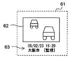
この押下に応じた信号(以下「一覧表示要求信号」という)は、表示装置14から接続部16を介して一覧表示制御部51に伝送される。一覧表示要求信号は、記録部5の記録内容を表示装置14の表示画面に一覧表示させることをドライブレコーダ1に要求する信号である。一覧表示制御部51は、接続部16を介して表示装置14との間で双方向通信が可能となっており、表示装置14に必要な表示等を行わせる。一覧表示制御部51は、一覧表示要求信号を受けたとき、記録部5に記録されているリスト情報に基づきつつ記録部5の記録内容を表示装置14に一覧表示させる。これによって、表示装置14の表示画面は図7のD2のようになる。図8は、或る1つの項目61を拡大した図である。図8において、図7と同一の部分には同一の符号を付している。
A signal corresponding to this depression (hereinafter referred to as “list display request signal”) is transmitted from the
表示画面D2には、合計9つの項目61が行列状に表示されている。各項目61の表示には、記録部5に記録された静止画像データを再生映像として表した静止画像62と、上記リスト情報によってその静止画像(静止画像データ)と関連付けられて記録されている関連情報63が含まれている。各関連情報63には、図8に示す如く、静止画像(静止画像データ)と関連付けられて記録されているトリガの種類、トリガの発生した日時、及びトリガが発生した時点における車両の位置(現在地)等が含められる。
A total of nine
項目61は、例えば表示画面D2上にて日時順に表示される。即ち、トリガの発生した日時が新しい項目ほど画面の上側(且つ左側)に表示される。但し、この表示の順番は適宜変更可能である。例えば、トリガの種類で表示する順番を決定してもよい。また、表示画面に同時に表示する項目61の数や表示画面上における項目61の配置方法は、如何様にも変形可能である。
The
図7は、表示画面D2上の最も左上の項目61が選択されている様子を表している。入力部15を操作することにより他の項目61を選択することもできる。選択された項目61を特定する信号は接続部16を介しつつ選択受付部52によって受け取られ、項目表示制御部53及び項目消去制御部54に伝達される。
FIG. 7 shows a state where the upper
そして、入力部15に所定の操作を施すことにより、表示装置14は選択した項目61に対応する動画像データの表示をドライブレコーダ1に要求することができる。この要求に応じた信号(以下「項目表示要求信号」)は、接続部16を介して表示装置14から項目表示制御部53に伝送される。項目表示制御部53は、接続部16を介して表示装置14との間で双方向通信が可能となっており、表示装置14に必要な表示等を行わせる。項目表示要求信号を受けた項目表示制御部53は、リスト情報に基づきつつ、選択された項目61に含まれる静止画像(静止画像データ)と関連付けられた動画像データを再生映像として表示装置14に表示させる。これによって、表示装置14の表示画面には所望の動画像が表示される。
Then, by performing a predetermined operation on the
また、入力部15に所定の操作を施すことにより、表示装置14は選択した項目61に対応する動画像データの消去をドライブレコーダ1に要求することができる。この要求に応じた信号(以下「項目消去要求信号」)は、接続部16を介して表示装置14から項目消去制御部54に伝送される。項目消去要求信号を受けた項目消去制御部54は、リスト情報に基づきつつ、選択された項目61に含まれる静止画像に対応する静止画像データと、その静止画像データに関連付けられた動画像データと、それらの静止画像データと動画像データとを関連付けているリスト情報を記録部5から消去する。
Further, by performing a predetermined operation on the
但し、特定の種類のトリガ(以下「第1特定トリガ」という)に対応する動画像データ(と静止画像データ及びリスト情報)の消去は禁止されている。この第1特定トリガとは、上述の「消去可否」の説明で述べたように、例えば衝突トリガである。例えば、表示装置14側にて、その第1特定トリガに対応する項目61の消去操作をできないようにしておく。また例えば、その第1特定トリガに対応する項目61についての項目消去要求信号を受けても、その項目61に対応する動画像データを消去しないように項目消去制御部54の動作を規制しておく。
However, deletion of moving image data (and still image data and list information) corresponding to a specific type of trigger (hereinafter referred to as “first specific trigger”) is prohibited. The first specific trigger is, for example, a collision trigger as described in the description of “deletability”. For example, the
また、車両の主電源遮断時において特定の種類のトリガ(以下「第2特定トリガ」といい、上記「第1特定トリガ」とは異なりうる)が発生した場合、一覧表示制御部51は、車両の主電源投入時に、第2特定トリガに対応する項目61を表示装置14に自動的に一覧表示させる。第2特定トリガとは、例えば、監視トリガである。これにより、表示装置14の表示画面は、図9のD3のようになる。図9において図7及び図8と同一の部分には同一の符号を付している。図9に示す如く、例えば、監視トリガに関する項目61だけを一覧表示させる。尚、図9は監視トリガに関する項目61が4つの場合の例を示している。また、図面の煩雑化防止のため、図9の表示画面D3においては関連情報63を図示していないが、図7の表示画面D2におけるものと同様の関連情報63が、表示画面D3における各項目61には表示される。
When a specific type of trigger (hereinafter referred to as “second specific trigger”, which may be different from the “first specific trigger”) occurs when the main power supply of the vehicle is shut off, the list
また、この一覧表示に加えて、或いはこの一覧表示に代えて、車両の主電源遮断時に監視トリガが発生していたことを知らせる表示内容(メッセージなど)を表示装置14に自動的に表示させてもよい。また、この表示を音声等に置換しても構わない。即ち、車両の主電源遮断時に監視トリガが発生していたこと表す報知を表示装置14に行わせればよい。上記のような報知を行う一覧表示制御部51は、報知手段として機能するとも言える。尚、車両の主電源遮断時とは、例えば車両を駆動させるエンジン(不図示)の停止時を意味し、車両の主電源投入時とは、例えばそのエンジンを始動させた時を意味する。エンジンを始動させた時とは、より詳しくは、イグニッションスイッチ(不図示)をオンすることにより、エンジンが動作していない状態から動作している状態に切り換わった時点、或いはその時点から所定時間(例えば、数ミリ秒〜数秒)の経過した時点を言う。
In addition to this list display or instead of this list display, display contents (such as a message) notifying that a monitoring trigger has occurred when the main power supply of the vehicle is cut off are automatically displayed on the
例えば、車両の主電源を遮断して車両を駐車場に駐車していたときに、不審者が車両内の物品の盗難を試みたり車両に危害(振動)を加えたりした場合は、監視トリガが発生する(発生しうる)。上記一覧表示や上記報知を行えば、このような事態が発生していたことを主電源投入時に容易に確認することができる。 For example, if the suspicious person attempts to steal an item in the vehicle or inflicts harm (vibration) on the vehicle when the vehicle's main power is shut off and the vehicle is parked in a parking lot, Occur (can occur). By performing the list display and the notification, it is possible to easily confirm that such a situation has occurred when the main power is turned on.
また、記録部5の空き容量が所定の容量以下になり、且つ記録部5の記録内容中に特定の種類のトリガ(以下「第3特定トリガ」といい、上記「第1特定トリガ」及び「第2特定トリガ」とは異なりうる)に応じて記録された動画像データ(及び静止画像データ)がある場合、一覧表示制御部51は、第3特定トリガに対応する項目61の一覧表示とその動画像データ(及び静止画像データ)の消去要請に関する報知を表示装置14に自動的に行わせる。上記のような報知を行う一覧表示制御部51は、報知手段として機能するとも言える。第3特定トリガとは、例えば、操作トリガ、要求トリガ及び監視トリガの内の何れか1以上のトリガである。また例えば、操作トリガと要求トリガの2つである。
In addition, the free capacity of the
第3特定トリガが操作トリガと要求トリガの2つの場合、例えば操作トリガと要求トリガに関する項目61だけ一覧表示させる。これに併せて「記録部5の記録容量が少なくなっていること」や「一覧表示されている項目に関わるデータを消去すべきであること」等を表示装置14に表示させる、或いは音声等で表現させる。このように一覧表示と報知を行うことで、使用者に余計な負担をかけることなく不要なデータが不要なデータ順に記録部5から消去されるようになる。また、一覧表示を行うことなく消去要請に関する上記報知だけを行うようにしても構わない。
When the third specific trigger is two of the operation trigger and the request trigger, for example, only the
尚、図5の一覧表示制御部51、選択受付部52、項目表示制御部53及び項目消去制御部54は、例えば主制御部10内や信号処理部3内に設けられる。
Note that the list
(走行時と駐停車時)
また、上述したように、比較部41において加速度の大きさGとの比較に用いられる上記閾値THは、車両の走行時においては第1の衝撃閾値TL1と等しいとされ、車両の駐停車時(停車時又は駐車時)には第2の衝撃閾値TL2と等しいとされる。従って、車両の走行時においては、加速度の大きさGが第1の衝撃閾値TL1以上となったときにトリガが発生する。一方、車両の駐停車時においては、加速度の大きさGが第2の衝撃閾値TL2以上となったときにトリガが発生する。ここで、停車時とは、「車両が停止していること」を少なくとも満たす時を言う。駐車時とは、「車両が停止していること」及び「運転者等の乗員が車両に乗車していないこと」を少なくとも満たす状態をいう。従って、駐車時は、停車時に含まれると捉えることもできる。
(During driving and parking)
Further, as described above, the threshold value TH used for comparison with the magnitude of acceleration G in the
車両の運転状態が走行時に対応した走行状態であるか、或いは駐停車時に対応した駐停車状態であるかは、例えば、加速度センサ31から与えられる加速度の大きさGから判断される。具体的には、検出された加速度の大きさGが所定時間(例えば数秒〜数10秒)、継続して所定の閾値以下であるとき(この条件を以下「条件A」という)、車両の運転状態は走行状態ではない(即ち、駐停車状態である)と判断される。他方、条件Aが不成立のとき、車両の運転状態は走行状態であると判断される。走行時における加速度の大きさは、加速や減速に伴って変動することが通常である。この加速や減速に伴う加速度の変動の有無を判別できるように条件Aの成立/不成立の判定に用いる上記閾値を設定しておく。
Whether the driving state of the vehicle is a traveling state corresponding to traveling or a parking / stopping state corresponding to parking is determined from, for example, the magnitude G of acceleration given from the
また例えば、撮像部2から得られる映像信号に基づくことによって、車両の運転状態が走行状態であるか或いは駐停車状態であるかを判別してもよい。車両が走行している場合、車両の外側を撮影した映像信号は刻一刻と変化するのが通常である。この変化があるか否かで、走行状態と駐停車状態とを切り分けるのである。また例えば、速度センサ13から与えられる車両の速度を特定する速度情報に基づくことによって、車両の運転状態が走行状態であるか或いは駐停車状態であるかを判別してもよい。
Further, for example, based on the video signal obtained from the
(車々間通信)
次に、通信回路33を介して行われる複数のドライブレコーダ1間の通信動作について説明する。図10は、ドライブレコーダ1が取付けられた車両を含む交通状態を示す図である。図1のドライブレコーダ1は、図10の車両C1、車両C2及び車両C4の夫々に取付けられている。尚、説明の簡略化上、車両C5にはドライブレコーダ1が取付けられていないものとする。図10において、車両C1、C2、C4及びC5の内部に示されている各矢印は、各車両の進行方向を示している。図10のC3は、交差点に設置されている信号機である。信号機C3には、画像記録装置(不図示)が取付けられている。この画像記録装置はドライブレコーダ1と同等の機能を有しているが、撮像部2、信号処理部3、バッファメモリ4、記録部5、主制御部10及び通信回路33以外の部位は、上記画像記録装置から割愛可能である。
(Vehicle communication)
Next, a communication operation between the plurality of
各主制御部10には、図示されない識別番号格納部からドライブレコーダ1及び画像記録装置の夫々に固有の識別番号が与えられている。車両C1、C2、C4に取付けられたドライブレコーダ1に設定された識別番号を、それぞれNo1、No2、No4とする。信号機C3に取付けられた画像記録装置に設定された識別番号を、No3とする。識別番号No1、No2、No3、No4は、互いに異なるように設定されている。このため、各識別番号は、対応する車両又は信号機を特定付けることになる。
Each
ドライブレコーダ1が取付けられた車両が衝突事故を起こした場合におけるドライブレコーダ1の動作を説明する。今、図10に示す如く、上方向に進行している車両C1に左側から、車両C5が衝突した場合を想定する。図11は、この衝突事故における各ドライブレコーダ1の動作及び信号機C3に取付けられた画像記録装置の動作を示すフローチャートである。図11において、左側に示すステップS1、S2、S5及びS6の処理は車両C1のドライブレコーダ1の動作を示し、右側に示すステップS3及びS4の処理は車両C2、C4のドライブレコーダ1の動作と信号機C3に取付けられた画像記録装置の動作を示している。
An operation of the
ステップS1において、比較部41は加速度センサ31によって検出された加速度の大きさが、上記の閾値TH以上となっているかを判断する。加速度の大きさが閾値TH(第1の衝撃閾値TL1)以上となっているとき、上述の如く衝突トリガが発生し、後述するステップS2に移行する(ステップS1のY)。一方、加速度の大きさが閾値TH(第1の衝撃閾値TL1)未満の場合は、ステップS1の処理が繰り返されることになる(ステップS1のN)。
In step S1, the
ステップS2において、車両C1に対応する主制御部10は、車両C1の周辺のドライブレコーダ1及び画像記録装置に対して第1要求信号を、通信回路33を介して送信すると共に、車両C1に対応する記録部5に自己記録データを記録させる。自己記録データには、衝突トリガの発生に応じて記録される動画像データ、静止画像データ及びリスト情報が含まれている。図10において、車両C1から車両C2、C4及び信号機C3に伸びる実線矢印は、第1要求信号が送信されている様子を示している。
In step S2, the
ステップS2を終えて移行するステップS3において、車両C2及びC4のドライブレコーダ1並びに信号機C3の画像記録装置は、各通信回路33を介して上記第1要求信号を受信する。これにより、各ドライブレコーダ1及び画像記録装置において、上記要求トリガが発生する。
In step S3, which is shifted to after finishing step S2, the
そして、車両C2のドライブレコーダ1において、主制御部10は記録部5に要求応答記録データを記録させると共に、車両C1のドライブレコーダ1に対して自身のドライブレコーダ1を特定づける識別番号No2を通信回路33を介して送信する(ステップS4)。同様に、車両C4のドライブレコーダ1において、主制御部10は記録部5に要求応答記録データを記録させると共に、車両C1のドライブレコーダ1に対して自身のドライブレコーダ1を特定づける識別番号No4を通信回路33を介して送信する(ステップS4)。同様に、信号機C3の画像記録装置において、主制御部10は記録部5に要求応答記録データを記録させると共に、車両C1のドライブレコーダ1に対して自身の画像記録装置を特定づける識別番号No3を通信回路33を介して送信する(ステップS4)。図10において、車両C2、C4及び信号機C3から車両C1に伸びる破線矢印は、各識別番号が送信されている様子を示している。
In the
各要求応答記録データには、要求トリガの発生に応じて記録される動画像データ、静止画像データ及びリスト情報が含まれている。 Each request response recording data includes moving image data, still image data, and list information recorded in response to the generation of a request trigger.
続くステップS5において、車両C1におけるドライブレコーダ1の主制御部10は、ステップS4において送信された識別番号No2、No4及びNo3を、通信回路33を介して受信する。そして、車両C1におけるドライブレコーダ1の主制御部10は、受信した識別番号を元に、車両C2及びC4に取付けられたドライブレコーダ1が記録した要求応答記録データ及び信号機C3に取付けられた画像記録装置が記録した要求応答記録データを順番に取得する(ステップS6)。この際、電波を中継する基地局(不図示)を介して各要求応答記録データを取得するようにしても良いし、要求応答記録データを一括して格納するセンターサーバ(不図示)を介して各要求応答記録データを取得するようにしても良い。センターサーバを利用する場合、各ドライブレコーダ1及び画像記録装置は、要求応答記録データを記録部5に記録することに加えて、要求応答記録データをセンターサーバに送信する必要がある。
In subsequent step S5, the
本発明に係る移動体用記録装置は、自動車や二輪車(所謂オートバイや電動自転車)等の車両の他、様々な移動体に搭載することが可能である。 The moving body recording apparatus according to the present invention can be mounted on various moving bodies in addition to vehicles such as automobiles and motorcycles (so-called motorcycles and electric bicycles).
1 ドライブレコーダ
2 撮像部
3 信号処理部
4 バッファメモリ(第1の記録部)
5 記録部(第2の記録部)
5a 動画像記録領域
5b 静止画像記録領域
5c リスト情報記録領域
6 トリガ発生部
7 静止画像作成部
8 リスト情報作成部
9 入力信号源
10 主制御部
11 GPS
12 時計装置
13 速度センサ
14 表示装置
15 入力部
16 接続部
31 加速度センサ
32 操作ボタン
33 通信回路
41 比較部
42 レベル判定部
43 状態検出部
44 信号判定部
45 トリガ生成判定部
51 一覧表示制御部
52 選択受付部
53 項目表示制御部
54 項目消去制御部
61 項目
62 静止画像
63 関連情報
D1、D2、D3 表示画面
C1、C2、C4、C5 車両
C3 信号機
DESCRIPTION OF
5 Recording unit (second recording unit)
5a Moving
DESCRIPTION OF
Claims (17)
撮像対象を撮影するための撮像部と、
前記撮像部からの映像信号に応じた画像データを作成する信号処理部と、
前記画像データを一時的に蓄積する第1の記録部と、
与えられた入力信号に応じて複数種類のトリガを発生可能なトリガ発生部と、
何れかの種類のトリガが発生したとき、そのトリガ発生時点を基準とした所定時点の画像データを含む動画像データを、前記第1の記録部の蓄積内容を参照しつつ記録する第2の記録部と、
何れかの種類のトリガが発生したとき、そのトリガ発生時点を基準とした所定時点の画像データより所定サイズの静止画像データを作成する静止画像作成部と、
発生したトリガの種類とそのトリガに応じて前記第2の記録部に記録された動画像データ及び静止画像データとを関連付けたリスト情報を作成するリスト情報作成部と、を備えた
ことを特徴とする移動体用記録装置。 A moving body recording apparatus attached to a moving body,
An imaging unit for imaging the imaging target;
A signal processing unit that creates image data according to a video signal from the imaging unit;
A first recording unit for temporarily storing the image data;
A trigger generation unit capable of generating a plurality of types of triggers according to a given input signal;
Second recording that records moving image data including image data at a predetermined time with reference to the trigger generation time when any type of trigger occurs, with reference to the stored content of the first recording unit And
When any type of trigger occurs, a still image creation unit that creates still image data of a predetermined size from image data at a predetermined time with reference to the trigger occurrence time;
A list information creating unit that creates list information that associates the type of the generated trigger and the moving image data and still image data recorded in the second recording unit in accordance with the trigger; A moving body recording apparatus.
ことを特徴とする請求項1に記載の移動体用記録装置。 The moving body according to claim 1, wherein when any type of trigger occurs, the still image creation unit creates the still image data from image data of a predetermined time before the trigger occurrence time. Recording device.
前記トリガ発生部は、前記加速度の大きさと2つ以上の閾値との比較結果に基づいてトリガを発生させるか否かと発生させるトリガの種類とを決定する
ことを特徴とする請求項1又は請求項2に記載の移動体用記録装置。 The input signal includes a signal for specifying the magnitude of acceleration of the moving body,
The trigger generation unit determines whether to generate a trigger based on a comparison result between the magnitude of the acceleration and two or more threshold values, and a type of trigger to be generated. 2. A recording apparatus for a moving body according to 2.
前記トリガ発生部は、その外部からの信号を受けたとき、その信号に対応した種類のトリガを発生させる
ことを特徴とする請求項3に記載の移動体用記録装置。 The input signal includes an external signal that requests recording of the moving image data by the second recording unit,
4. The moving body recording apparatus according to claim 3, wherein the trigger generator generates a trigger of a type corresponding to the signal when receiving the signal from the outside.
前記入力信号には、前記通信回路を介して受信した他の移動体用記録装置からの所定の要求信号が含まれ、
前記トリガ発生部は、前記通信回路を介して前記要求信号を受信したとき、その受信に対応した種類のトリガを発生させる
ことを特徴とする請求項3に記載の移動体用記録装置。 A communication circuit for performing bidirectional communication with another mobile recording device;
The input signal includes a predetermined request signal from another mobile recording device received via the communication circuit,
4. The moving body recording apparatus according to claim 3, wherein when the request signal is received via the communication circuit, the trigger generator generates a trigger of a type corresponding to the reception.
前記トリガ発生部は、前記操作信号を受けたとき、その操作信号に対応した種類のトリガを発生させる
ことを特徴とする請求項3〜請求項5の何れかに記載の移動体用記録装置。 The input signal includes an operation signal generated by an external operation,
6. The moving body recording apparatus according to claim 3, wherein when the operation signal is received, the trigger generation unit generates a type of trigger corresponding to the operation signal. 7.
前記複数種類のトリガとは、第1のトリガ、第2のトリガ、・・・、第nのトリガ(nは2以上の整数)であり、
前記加速度の大きさが所定の第1の閾値以上に達したとき、前記トリガ発生部は第1のトリガを発生させ、且つ前記第2の記録部は、そのトリガ発生時点の所定時間前の画像データを含む動画像データを記録する
ことを特徴とする請求項1又は請求項2に記載の移動体用記録装置。 The input signal includes a signal for specifying the magnitude of acceleration of the moving body,
The plurality of types of triggers are a first trigger, a second trigger, ..., an nth trigger (n is an integer of 2 or more),
When the magnitude of the acceleration reaches a predetermined first threshold value or more, the trigger generation unit generates a first trigger, and the second recording unit displays an image a predetermined time before the trigger generation time. The moving image recording apparatus according to claim 1, wherein moving image data including data is recorded.
ことを特徴とする請求項7に記載の移動体用記録装置。 When the magnitude of the acceleration reaches or exceeds a predetermined second threshold value smaller than the first threshold value when the moving body is parked or stopped, the trigger generation unit generates a second trigger, and the second 8. The recording unit according to claim 7, wherein the recording unit records moving image data including at least one of image data of a predetermined time before the trigger occurrence time and image data after the time point. Mobile recording device.
ことを特徴とする請求項7又は請求項8に記載の移動体用記録装置。 The mobile signal according to claim 7 or 8, wherein the signal processing unit performs encryption processing on moving image data to be recorded by the second recording unit when the first trigger is generated. Recording device.
外部の表示装置と有線或いは無線にて接続するための接続手段と、
前記第2の記録部の記録内容の一覧表示要求を受け付けるとともに、一覧表示要求を受けたとき、前記リスト情報に基づきつつ前記表示装置に前記記録内容を項目で区分けして一覧表示させる一覧表示制御手段と、を更に備えた
ことを特徴とする請求項1〜請求項9の何れかに記載の移動体用記録装置。 The still image data and the list information are recorded in the second recording unit, and the moving body recording device includes:
A connection means for connecting to an external display device by wire or wirelessly;
A list display control for receiving a list display request for the recorded contents of the second recording unit and displaying the list by dividing the recorded contents into items on the display device based on the list information when the list display request is received 10. The moving body recording apparatus according to claim 1, further comprising: means.
前記リスト情報に基づきつつ選択された項目に対応する動画像データを再生映像として前記表示装置に表示させる項目表示制御手段と、を更に備えた
ことを特徴とする請求項10に記載の移動体用記録装置。 Selection accepting means for accepting selection of items included in the list display displayed by the list display control means;
11. The mobile object according to claim 10, further comprising item display control means for causing the display device to display moving image data corresponding to an item selected based on the list information as a reproduced video. Recording device.
前記リスト情報に基づきつつ選択された項目に対応する動画像データを前記第2の記録部から消去する項目消去制御手段と、を更に備えた
ことを特徴とする請求項10に記載の移動体用記録装置。 Selection accepting means for accepting selection of items included in the list display displayed by the list display control means;
11. The mobile object according to claim 10, further comprising item erasure control means for erasing moving image data corresponding to an item selected based on the list information from the second recording unit. Recording device.
ことを特徴とする請求項10〜請求項12の何れかに記載の移動体用記録装置。 When a specific type of trigger occurs when the main power source of the mobile body is shut down, the list display control unit is configured to display items corresponding to the specific type of trigger when the main power source of the mobile body is turned on. The moving body recording apparatus according to claim 10, wherein the display apparatus automatically performs list display.
ことを特徴とする請求項12に記載の移動体用記録装置。 When the free capacity of the second recording unit is equal to or less than a predetermined capacity and there is moving image data recorded in response to a specific type of trigger in the recording content of the second recording unit, the list display control 13. The mobile device according to claim 12, wherein the means automatically causes the display device to perform a list display of items corresponding to the specific type of trigger and a notification regarding a request to delete the moving image data. Recording device.
ことを特徴とする請求項12に記載の移動体用記録装置。 13. The moving body recording apparatus according to claim 12, wherein erasing of moving image data recorded in the second recording unit in accordance with a specific type of trigger is prohibited.
ことを特徴とする請求項1〜請求項9の何れかに記載の移動体用記録装置。 Notification means for automatically causing an external display device to notify the occurrence of the occurrence of a specific type of trigger when the main power of the mobile body is cut off when the main power of the mobile body is turned on The moving body recording apparatus according to claim 1, further comprising:
ことを特徴とする請求項1〜請求項9の何れかに記載の移動体用記録装置。 When the free capacity of the second recording unit is equal to or less than a predetermined capacity and there is moving image data recorded in response to a specific type of trigger in the recording content of the second recording unit, the moving image data The mobile recording apparatus according to claim 1, further comprising a notification unit that automatically causes an external display device to perform a notification regarding an erasure request.
Priority Applications (1)
| Application Number | Priority Date | Filing Date | Title |
|---|---|---|---|
| JP2005048753A JP4467448B2 (en) | 2005-02-24 | 2005-02-24 | Mobile recording device |
Applications Claiming Priority (1)
| Application Number | Priority Date | Filing Date | Title |
|---|---|---|---|
| JP2005048753A JP4467448B2 (en) | 2005-02-24 | 2005-02-24 | Mobile recording device |
Publications (2)
| Publication Number | Publication Date |
|---|---|
| JP2006237974A JP2006237974A (en) | 2006-09-07 |
| JP4467448B2 true JP4467448B2 (en) | 2010-05-26 |
Family
ID=37045152
Family Applications (1)
| Application Number | Title | Priority Date | Filing Date |
|---|---|---|---|
| JP2005048753A Expired - Fee Related JP4467448B2 (en) | 2005-02-24 | 2005-02-24 | Mobile recording device |
Country Status (1)
| Country | Link |
|---|---|
| JP (1) | JP4467448B2 (en) |
Families Citing this family (39)
| Publication number | Priority date | Publication date | Assignee | Title |
|---|---|---|---|---|
| JP4903443B2 (en) * | 2006-01-23 | 2012-03-28 | 富士通テン株式会社 | Drive recorder |
| JP2008078793A (en) * | 2006-09-19 | 2008-04-03 | Casio Comput Co Ltd | Digital camera system |
| JP2008124768A (en) * | 2006-11-10 | 2008-05-29 | Fujitsu Ten Ltd | Apparatus and method for information processing, and program |
| JP4901498B2 (en) * | 2007-01-19 | 2012-03-21 | 富士通テン株式会社 | Thumbnail image display method |
| JP2008186174A (en) * | 2007-01-29 | 2008-08-14 | Toyota Motor Corp | Running state recording device |
| JP2008269494A (en) * | 2007-04-24 | 2008-11-06 | Auto Network Gijutsu Kenkyusho:Kk | On-vehicle imaging system |
| JP2008293083A (en) * | 2007-05-22 | 2008-12-04 | Optex Co Ltd | Operation monitoring device with camera |
| JP4859756B2 (en) * | 2007-05-31 | 2012-01-25 | 富士通テン株式会社 | Image recording condition setting method in drive recorder |
| JP2009032143A (en) * | 2007-07-30 | 2009-02-12 | Seiko Epson Corp | Drive recorder, drive recorder system, method for controlling drive recorder, and program |
| JP5293988B2 (en) * | 2007-08-07 | 2013-09-18 | オムロン株式会社 | Operation information recording apparatus, information processing method, and program |
| JP5025557B2 (en) * | 2008-05-02 | 2012-09-12 | キヤノン株式会社 | Image photographing apparatus, control method therefor, and program |
| JP2010102601A (en) * | 2008-10-27 | 2010-05-06 | Rohm Co Ltd | Vehicle traveling information recording device |
| CN102067191A (en) | 2008-06-30 | 2011-05-18 | 罗姆股份有限公司 | Vehicle traveling information recording device |
| JP2010111146A (en) * | 2008-11-04 | 2010-05-20 | Rohm Co Ltd | Automatic control apparatus for vehicular headlight |
| JP5314338B2 (en) * | 2008-06-30 | 2013-10-16 | ローム株式会社 | Vehicle abnormality recording device |
| JP5174594B2 (en) * | 2008-09-16 | 2013-04-03 | シナノケンシ株式会社 | Driving information recording device |
| JP2010122947A (en) * | 2008-11-20 | 2010-06-03 | Toshiba Corp | Information recording device |
| JP4999901B2 (en) * | 2009-09-18 | 2012-08-15 | 富士通テン株式会社 | Driving assistance device |
| JP2011077952A (en) * | 2009-09-30 | 2011-04-14 | Toshiba Corp | Video-recording apparatus and recording management method |
| JP5424861B2 (en) * | 2009-12-25 | 2014-02-26 | 富士通テン株式会社 | Drive recorder, recording method and program |
| JP2010182325A (en) * | 2010-03-15 | 2010-08-19 | Fujitsu Ten Ltd | Image display method and image display device |
| JP2012064126A (en) * | 2010-09-17 | 2012-03-29 | Yupiteru Corp | Drive recorder |
| JP5960391B2 (en) * | 2011-05-23 | 2016-08-02 | 矢崎エナジーシステム株式会社 | Operation information recording device |
| JP5856470B2 (en) * | 2011-12-20 | 2016-02-09 | Kyb株式会社 | Drive recorder |
| JP5856477B2 (en) * | 2011-12-28 | 2016-02-09 | Kyb株式会社 | Drive recorder |
| JP2013156674A (en) * | 2012-01-26 | 2013-08-15 | Kayaba Ind Co Ltd | Drive recorder |
| JP2013182421A (en) * | 2012-03-01 | 2013-09-12 | Yupiteru Corp | Vehicle information recording device, vehicle information recording system and program |
| JP2013196330A (en) * | 2012-03-19 | 2013-09-30 | Kayaba Ind Co Ltd | Drive recorder |
| JP5934548B2 (en) * | 2012-03-29 | 2016-06-15 | 矢崎エナジーシステム株式会社 | In-vehicle image recording device |
| JP5914135B2 (en) * | 2012-04-20 | 2016-05-11 | 矢崎エナジーシステム株式会社 | Drive recorder |
| JP5324722B1 (en) * | 2012-12-27 | 2013-10-23 | アサヒリサーチ株式会社 | Video recording / playback device |
| JP5602267B2 (en) * | 2013-03-05 | 2014-10-08 | 富士通テン株式会社 | Vehicle running status display method |
| JP6503692B2 (en) * | 2014-10-31 | 2019-04-24 | 株式会社トランストロン | Image transmitting apparatus, image acquiring method, and image acquiring program |
| JP6693357B2 (en) * | 2016-09-13 | 2020-05-13 | 株式会社Jvcケンウッド | Image recording apparatus, image recording method and program |
| JP6866728B2 (en) * | 2017-03-30 | 2021-04-28 | 沖電気工業株式会社 | Communication unit, notification system, and status attribute determination program |
| JP6398021B1 (en) * | 2018-01-09 | 2018-09-26 | 株式会社フローディア | Solid-state imaging device and camera system |
| JP7326719B2 (en) * | 2018-10-25 | 2023-08-16 | 株式会社Jvcケンウッド | RECORDING/PLAYBACK CONTROL DEVICE, RECORDING/PLAYBACK CONTROL METHOD, AND RECORDING/PLAYBACK CONTROL PROGRAM |
| US10890907B2 (en) * | 2018-12-14 | 2021-01-12 | Toyota Jidosha Kabushiki Kaisha | Vehicle component modification based on vehicular accident reconstruction data |
| JP7123877B2 (en) * | 2019-08-13 | 2022-08-23 | 日立建機株式会社 | system of record |
-
2005
- 2005-02-24 JP JP2005048753A patent/JP4467448B2/en not_active Expired - Fee Related
Also Published As
| Publication number | Publication date |
|---|---|
| JP2006237974A (en) | 2006-09-07 |
Similar Documents
| Publication | Publication Date | Title |
|---|---|---|
| JP4467448B2 (en) | Mobile recording device | |
| JP4971625B2 (en) | Driving support device and driving information calculation system | |
| JP6945226B2 (en) | In-vehicle electronic devices, client terminals, and programs | |
| US10958866B2 (en) | Recording apparatus, recording method, and a non-transitory computer readable medium | |
| US9098388B2 (en) | Apparatus and method for recording an image for a vehicle using on board diagnostic information | |
| JP2006235732A (en) | Drive recorder | |
| JP6534103B2 (en) | Recording apparatus and image reproduction method | |
| JP6669240B1 (en) | Recording control device, recording control system, recording control method, and recording control program | |
| KR20090063064A (en) | Apparatus and method of recoding driving information for vehicle and storage media having program source thereof | |
| JP6962712B2 (en) | In-vehicle image recording device | |
| JP2007141211A (en) | Driving assisting method and driving assisting device | |
| JPWO2008105062A1 (en) | Information recording apparatus, information recording method, information recording program, and recording medium | |
| JP5180450B2 (en) | Driving support method and driving support device | |
| JP6216569B2 (en) | Drive recorder | |
| CN112639893B (en) | Vehicle recording control device, vehicle imaging device, vehicle recording control method, and program | |
| KR100791523B1 (en) | Digital video recorder system for car | |
| JP2023051997A (en) | On-vehicle video recording device and control method thereof | |
| JP6774611B2 (en) | Recording control device, recording device, recording control method and recording control program | |
| KR20130099332A (en) | A vehicular black box using gps data and specific map data, and a recording method for a vehicular black box | |
| JP2020053995A (en) | Electronic apparatus and program | |
| JP7427895B2 (en) | Vehicle recording control device, vehicle recording device, vehicle recording control method and program | |
| JP7326719B2 (en) | RECORDING/PLAYBACK CONTROL DEVICE, RECORDING/PLAYBACK CONTROL METHOD, AND RECORDING/PLAYBACK CONTROL PROGRAM | |
| JP6804676B1 (en) | Programs, information recording devices and information recording methods | |
| JP6643640B2 (en) | Electronic devices and programs | |
| JP2003123191A (en) | Vehicle management system |
Legal Events
| Date | Code | Title | Description |
|---|---|---|---|
| A621 | Written request for application examination |
Free format text: JAPANESE INTERMEDIATE CODE: A621 Effective date: 20080123 |
|
| A977 | Report on retrieval |
Free format text: JAPANESE INTERMEDIATE CODE: A971007 Effective date: 20090520 |
|
| A131 | Notification of reasons for refusal |
Free format text: JAPANESE INTERMEDIATE CODE: A131 Effective date: 20091027 |
|
| A521 | Request for written amendment filed |
Free format text: JAPANESE INTERMEDIATE CODE: A523 Effective date: 20091218 |
|
| TRDD | Decision of grant or rejection written | ||
| A01 | Written decision to grant a patent or to grant a registration (utility model) |
Free format text: JAPANESE INTERMEDIATE CODE: A01 Effective date: 20100126 |
|
| A01 | Written decision to grant a patent or to grant a registration (utility model) |
Free format text: JAPANESE INTERMEDIATE CODE: A01 |
|
| A61 | First payment of annual fees (during grant procedure) |
Free format text: JAPANESE INTERMEDIATE CODE: A61 Effective date: 20100223 |
|
| R151 | Written notification of patent or utility model registration |
Ref document number: 4467448 Country of ref document: JP Free format text: JAPANESE INTERMEDIATE CODE: R151 |
|
| FPAY | Renewal fee payment (event date is renewal date of database) |
Free format text: PAYMENT UNTIL: 20130305 Year of fee payment: 3 |
|
| FPAY | Renewal fee payment (event date is renewal date of database) |
Free format text: PAYMENT UNTIL: 20140305 Year of fee payment: 4 |
|
| S531 | Written request for registration of change of domicile |
Free format text: JAPANESE INTERMEDIATE CODE: R313531 |
|
| R360 | Written notification for declining of transfer of rights |
Free format text: JAPANESE INTERMEDIATE CODE: R360 |
|
| R360 | Written notification for declining of transfer of rights |
Free format text: JAPANESE INTERMEDIATE CODE: R360 |
|
| R371 | Transfer withdrawn |
Free format text: JAPANESE INTERMEDIATE CODE: R371 |
|
| S531 | Written request for registration of change of domicile |
Free format text: JAPANESE INTERMEDIATE CODE: R313531 |
|
| R350 | Written notification of registration of transfer |
Free format text: JAPANESE INTERMEDIATE CODE: R350 |
|
| RD03 | Notification of appointment of power of attorney |
Free format text: JAPANESE INTERMEDIATE CODE: R3D03 |
|
| LAPS | Cancellation because of no payment of annual fees |