JP4466331B2 - Inkjet recording head and inkjet recording apparatus - Google Patents
Inkjet recording head and inkjet recording apparatus Download PDFInfo
- Publication number
- JP4466331B2 JP4466331B2 JP2004322341A JP2004322341A JP4466331B2 JP 4466331 B2 JP4466331 B2 JP 4466331B2 JP 2004322341 A JP2004322341 A JP 2004322341A JP 2004322341 A JP2004322341 A JP 2004322341A JP 4466331 B2 JP4466331 B2 JP 4466331B2
- Authority
- JP
- Japan
- Prior art keywords
- ink
- flow path
- beam member
- nozzle
- jet recording
- Prior art date
- Legal status (The legal status is an assumption and is not a legal conclusion. Google has not performed a legal analysis and makes no representation as to the accuracy of the status listed.)
- Expired - Fee Related
Links
- 239000000976 ink Substances 0.000 description 211
- 238000000034 method Methods 0.000 description 11
- 238000006073 displacement reaction Methods 0.000 description 9
- 238000005452 bending Methods 0.000 description 7
- 238000007599 discharging Methods 0.000 description 6
- 230000006835 compression Effects 0.000 description 5
- 238000007906 compression Methods 0.000 description 5
- 230000000740 bleeding effect Effects 0.000 description 4
- 238000010438 heat treatment Methods 0.000 description 4
- 239000007788 liquid Substances 0.000 description 4
- XLYOFNOQVPJJNP-UHFFFAOYSA-N water Substances O XLYOFNOQVPJJNP-UHFFFAOYSA-N 0.000 description 3
- PEDCQBHIVMGVHV-UHFFFAOYSA-N Glycerine Chemical compound OCC(O)CO PEDCQBHIVMGVHV-UHFFFAOYSA-N 0.000 description 2
- 238000013459 approach Methods 0.000 description 2
- 238000001035 drying Methods 0.000 description 2
- 229920006332 epoxy adhesive Polymers 0.000 description 2
- 230000003287 optical effect Effects 0.000 description 2
- 229920005989 resin Polymers 0.000 description 2
- 239000011347 resin Substances 0.000 description 2
- 230000008961 swelling Effects 0.000 description 2
- 230000001133 acceleration Effects 0.000 description 1
- 230000002411 adverse Effects 0.000 description 1
- 238000013461 design Methods 0.000 description 1
- 230000006866 deterioration Effects 0.000 description 1
- 230000000694 effects Effects 0.000 description 1
- 238000005516 engineering process Methods 0.000 description 1
- 238000002474 experimental method Methods 0.000 description 1
- 239000011521 glass Substances 0.000 description 1
- 235000011187 glycerol Nutrition 0.000 description 1
- 238000000059 patterning Methods 0.000 description 1
- 238000000206 photolithography Methods 0.000 description 1
- 239000000049 pigment Substances 0.000 description 1
- 229920001721 polyimide Polymers 0.000 description 1
- 229920006254 polymer film Polymers 0.000 description 1
- 230000002265 prevention Effects 0.000 description 1
- 238000007639 printing Methods 0.000 description 1
- 238000012545 processing Methods 0.000 description 1
- 229910000679 solder Inorganic materials 0.000 description 1
- 239000000758 substrate Substances 0.000 description 1
- 230000001629 suppression Effects 0.000 description 1
Images


Classifications
-
- B—PERFORMING OPERATIONS; TRANSPORTING
- B41—PRINTING; LINING MACHINES; TYPEWRITERS; STAMPS
- B41J—TYPEWRITERS; SELECTIVE PRINTING MECHANISMS, i.e. MECHANISMS PRINTING OTHERWISE THAN FROM A FORME; CORRECTION OF TYPOGRAPHICAL ERRORS
- B41J2/00—Typewriters or selective printing mechanisms characterised by the printing or marking process for which they are designed
- B41J2/005—Typewriters or selective printing mechanisms characterised by the printing or marking process for which they are designed characterised by bringing liquid or particles selectively into contact with a printing material
- B41J2/01—Ink jet
- B41J2/135—Nozzles
- B41J2/14—Structure thereof only for on-demand ink jet heads
Landscapes
- Particle Formation And Scattering Control In Inkjet Printers (AREA)
Description
本発明は、インクジェット記録ヘッドおよびインクジェット記録装置に関する。 The present invention relates to an ink jet recording head and an ink jet recording apparatus.
現在市販されている水性インクジェットプリンターは、概ね粘度5cps前後、高々10cpsオーダの染料インクや顔料インクを採用している。媒体に着弾した際のインク滲み防止や、光学的な色濃度アップ、含水量低減による媒体の膨潤抑制/短時間乾燥、あるいは、そうした高品質インクをトータル設計するに当たり自由度が大きくとれる等の理由から、インク粘度を増加することによってプリント性能は向上できることが知られている。 Water-based inkjet printers currently on the market generally employ dye inks and pigment inks having a viscosity of about 5 cps and an order of 10 cps at most. Reasons such as prevention of ink bleeding when landing on the medium, increase in optical color density, suppression of swelling / short time drying of the medium due to reduced water content, or greater freedom in total design of such high quality ink Therefore, it is known that the printing performance can be improved by increasing the ink viscosity.
反面、高粘度インクを吐出するには、高出力な圧力発生機構が必要であり、コストやヘッドサイズ増加等の弊害を招く。従来からイジェクターにヒーターを別途設け、吐出時のインク粘度を強制的に下げる技術は公知である(例えば、特許文献1参照)が、インクを加熱する上記の方法はインク劣化や流路のダメージを早める根本課題があり、また使用できるインクも熱による劣化のないものに制限される。 On the other hand, in order to eject high-viscosity ink, a high-output pressure generation mechanism is required, which causes adverse effects such as an increase in cost and head size. Conventionally, a technique for forcibly lowering the ink viscosity at the time of ejection by separately providing a heater in the ejector is known (see, for example, Patent Document 1). However, the above-described method of heating ink causes ink deterioration and flow path damage. There is a fundamental problem to be accelerated, and the ink that can be used is limited to one that does not deteriorate by heat.
このほか、インク吐出する際の逆方向へのインク流を梁状の弁によって抑制し、より高粘度なインクを吐出する技術(例えば、特許文献2参照)が開示されている。 In addition, there is disclosed a technique (for example, see Patent Document 2) in which ink flow in the reverse direction when ink is ejected is suppressed by a beam-like valve and ink with higher viscosity is ejected.
大変形が得られる座屈曲がりを利用し、圧力発生機構自体をパワーアップする方法として、発熱体層との熱膨張差で変形するダイヤフラム状アクチュエータを使用した技術(例えば、特許文献3参照)、また、同様の構成で片持ち梁状のアクチュエータを使用した技術(例えば、特許文献4参照)が開示されている。 As a method of powering up the pressure generation mechanism itself using a seat bending beam that can obtain a large deformation, a technique using a diaphragm actuator that deforms due to a difference in thermal expansion with the heating element layer (see, for example, Patent Document 3), Further, a technique using a cantilever-like actuator with the same configuration (for example, see Patent Document 4) is disclosed.
例えば図8に示すインクジェット記録ヘッド100はインク室106中のインク101をアクチュエータ102を図8(a)から図8(b)のように変形させることによって急激に加圧し、ノズル104からインク滴108として吐出させる。
For example, the ink
しかしながら、上記の従来技術でも、粘度10cpsを大きく上回る50〜100cpsのような高粘度インクを、常温において安定吐出することは極めて困難である。本発明の目的は、これらの課題を解決し、特に常温で50〜100cpsオーダの高粘度インクが吐出可能なインクジェット記録ヘッドを提供することにある。具体的には、梁に圧縮と回転運動を与え、座屈曲げ方向が反転する際の急峻な上下運動を利用し、ノズルからインク滴を慣性離脱させるインクジェット記録ヘッドおよびインクジェット記録装置を提供する。
本発明は上記事実を考慮し、常温で高粘度インクを吐出可能なインクジェット記録ヘッドおよびインクジェット記録装置を提供することを目的とする。 In view of the above facts, the present invention has an object to provide an ink jet recording head and an ink jet recording apparatus capable of discharging high viscosity ink at room temperature.
請求項1に記載のインクジェット記録ヘッドは、内部にインク流路を備えたインク流路部材と、前記インク流路部材と接合され一体に変形する梁部材と、前記インク流路部材の長手方向略中央に設けられ、インク滴を吐出するノズルと、を備え、両側から押圧され両端を保持された前記梁部材を長手方向両側から押圧すると共にインク滴吐出方向に凹となるように弾性曲げ変形させた後、インク滴吐出方向に凸となるように弾性曲げ変形させて前記梁部材を座屈反転変形させ、前記ノズル内部のインクに吐出方向の慣性を与え、インク滴として前記ノズルより吐出させる駆動手段を有することを特徴とする。 The ink jet recording head according to claim 1 , wherein an ink flow path member having an ink flow path therein, a beam member joined to the ink flow path member and deformed integrally, and substantially the longitudinal direction of the ink flow path member. A nozzle provided at the center for ejecting ink droplets, and pressing the beam member pressed from both sides and held at both ends from both sides in the longitudinal direction and elastically deformed to be concave in the ink droplet ejection direction. and then, the beam member resiliently bent is deformed so as to project into the ink drop discharge direction is buckling reversed deformation, given the inertia of discharge direction to the ink inside the nozzle, the drive to eject from the nozzle as ink droplets It has the means .
上記構成の発明では、ノズルが設けられたインク流路部材と接合され、一体に変形する梁部材を長手方向両側から押圧すると共にインク滴吐出方向に凹から凸となるように弾性曲げ変形させ、座屈反転変形させることで、ノズルからインク滴を慣性離脱させて吐出する方法を用いたので、従来のサーマルあるいはピエゾ方式などに比較してインクの粘性が高くても吐出可能となる。 In the invention of the above configuration, the beam member that is joined to the ink flow path member provided with the nozzle and is integrally deformed is pressed from both sides in the longitudinal direction and elastically bent and deformed so as to be convex from the concave in the ink droplet ejection direction, By performing the buckling reversal deformation, the method of discharging ink droplets from the nozzle by inertia is used, so that even if the ink viscosity is higher than that of the conventional thermal or piezo method, the ink can be discharged.
請求項2に記載のインクジェット記録ヘッドは、前記駆動手段は前記梁部材の長手方向両端または一端を保持して回動自在であり、前記梁部材がインク滴吐出方向に凹となるように回動したのち、前記梁部材がインク滴吐出方向に凸となるように座屈反転変形させ、前記ノズル近傍のインクに吐出方向の慣性を与えノズルより吐出させることを特徴とする。
An ink jet recording head according to
上記構成の発明では、駆動手段によって吐出方向に凹となるように予備変形させた梁部材を凸に座屈反転させインク滴を吐出させることで、予備変形の有無によって座屈反転の有無すなわちインク滴の吐出の有無を制御できる。 In the invention having the above-described configuration, the presence or absence of buckling reversal, that is, ink is determined by the presence or absence of preliminary deformation by ejecting ink droplets by buckling and reversing the beam member that has been preliminarily deformed so as to be concave in the ejection direction by the driving means Whether or not droplets are discharged can be controlled.
請求項3に記載のインクジェット記録ヘッドは、内部にインク流路を備えたインク流路部材と、前記インク流路部材と接合され一体に変形する梁部材と、前記インク流路部材の長手方向略中央に設けられ、インク滴を吐出するノズルと、前記梁部材の両端を保持する保持部材と、前記保持部材の一方または両方を支持し、回動して前記梁部材を押圧する回転エンコーダと、を備え、前記保持部材は前記回転エンコーダの回転中心よりオフセットして支持されることにより、前記回転エンコーダの回転によって前記梁部材を長手方向両側から押圧すると共にインク滴吐出方向に凹となるように弾性曲げ変形させた後、インク滴吐出方向に凸となるように曲げ変形させて前記梁部材を座屈反転変形させ、前記ノズル内部のインクに吐出方向の慣性を与え、インク滴として前記ノズルより吐出させることを特徴とする。 An ink jet recording head according to claim 3 , wherein an ink flow path member having an ink flow path therein, a beam member joined to the ink flow path member and deformed integrally, and substantially the longitudinal direction of the ink flow path member. A nozzle provided in the center for discharging ink droplets, a holding member for holding both ends of the beam member, a rotary encoder for supporting one or both of the holding members and rotating to press the beam member ; The holding member is supported by being offset from the rotation center of the rotary encoder, so that the beam member is pressed from both sides in the longitudinal direction by the rotation of the rotary encoder and is recessed in the ink droplet ejection direction. after elastically bending deformation, the beam member is bent to deform so as to project into the ink drop discharge direction is buckling reversed deformation, the inertia of the discharge direction to the ink inside the nozzle Given, wherein the ejected from the nozzle as ink droplets.
上記構成の発明では、梁部材に加える圧縮量すなわちエンコーダの回転量によって梁部材の座屈反転の有無、つまりインク滴の吐出の有無を制御できる。 In the invention with the above configuration, the presence or absence of buckling inversion of the beam member, that is, the presence or absence of ink droplet ejection, can be controlled by the amount of compression applied to the beam member, that is, the amount of rotation of the encoder.
請求項4に記載のインクジェット記録ヘッドは、前記回転エンコーダの回転角度を変更することで前記梁部材の前記ノズル近傍におけるインク滴吐出方向の移動距離を制御し、前記移動距離の長短で前記ノズル近傍のインクに加わる慣性の大小を制御することにより、吐出されるインク滴の大小を制御することを特徴とする。 The ink jet recording head according to claim 4 , wherein the moving distance of the beam member in the vicinity of the nozzle in the vicinity of the nozzle is controlled by changing the rotation angle of the rotary encoder, The size of the ink droplets ejected is controlled by controlling the magnitude of inertia applied to the ink.
上記構成の発明では、梁部材に加える圧縮量すなわちエンコーダの回転量によってインク滴に加わる慣性の大きさ、つまりインク滴の大小を制御できる。 In the invention with the above configuration, the magnitude of inertia applied to the ink droplet, that is, the size of the ink droplet can be controlled by the compression amount applied to the beam member, that is, the rotation amount of the encoder.
請求項5に記載のインクジェット記録ヘッドは、内部にインク流路を備えたインク流路部材と、前記インク流路部材の長手方向略中央に設けられ、インク滴を吐出するノズルと、前記インク流路部材と接合され、もしくは前記インク流路部材を含み、予め長手方向両側から押圧されると共に、インク滴吐出方向と反対側に、インク滴吐出方向に凹となる方向に曲げて配置された梁部材と、前記梁部材をインク滴吐出方向に凸となる方向に撓ませるアクチュエータと、を備え、前記アクチュエータはインク滴吐出方向に凹となった前記梁部材を、インク滴吐出方向に凸となる方向に座屈反転させ、前記インク流路内部のインクに吐出方向の慣性を与えることで前記ノズルからインク滴を吐出させることを特徴とする。
The ink jet recording head according to
上記構成の発明では、吐出方向に凹となる予備変形を加えた梁部材をアクチュエータで凸方向に座屈変形させてインク滴を吐出させることで、単純な構造で高粘度インクを吐出可能とできる。 In the invention with the above configuration, it is possible to eject high-viscosity ink with a simple structure by ejecting ink droplets by buckling deformation of the beam member, which is concavely deformed in the ejection direction, with the actuator in the convex direction. .
請求項6に記載のインクジェット記録ヘッドは、前記アクチュエータは、前記梁部材の長手方向長さの略半分にわたって設けられたことを特徴とする。 An ink jet recording head according to a sixth aspect of the invention is characterized in that the actuator is provided over substantially half of the longitudinal length of the beam member.
上記構成の発明では、アクチュエータを梁部材の略半分の長さとしたことで、座屈反転の撓みが最も大きくなる梁中央部においてアクチュエータが破損することが防止され、座屈変形を起こす箇所を梁部材の中央近傍に規定できる。 In the invention having the above-described configuration, the actuator is approximately half the length of the beam member, so that the actuator is prevented from being damaged at the center of the beam where the deflection of the buckling reversal is the largest, and the location where the buckling deformation occurs is the beam. It can be defined near the center of the member.
請求項7に記載のインクジェット記録ヘッドは、前記アクチュエータはピエゾアクチュエータであることを特徴とする。 The ink jet recording head according to claim 7 is characterized in that the actuator is a piezo actuator.
上記構成の発明では、比較的低い応答速度でよいアクチュエータに大変位が得られるピエゾ素子を用いることで、安価で信頼性の高いインクジェット記録ヘッドとすることができる。 In the invention having the above-described configuration, an inexpensive and highly reliable ink jet recording head can be obtained by using a piezo element capable of obtaining a large displacement for an actuator that requires a relatively low response speed.
請求項8に記載のインクジェット記録装置は、請求項1〜請求項7のいすれか1項に記載のインクジェット記録ヘッドを使用したことを特徴とする。 An ink jet recording apparatus according to claim 8, characterized in that using an ink jet recording head according to Isure one of claims 1 to claim 7.
上記構成の発明では、高粘度のインクを記録媒体に吐出させることができる。従来のインクジェット記録装置と比較して、滲みのない優れた品質の記録を行うことができる。 In the invention with the above configuration, high-viscosity ink can be ejected onto a recording medium. Compared with a conventional ink jet recording apparatus, it is possible to perform recording with excellent quality without bleeding.
本発明は上記構成としたので、常温で高粘度インクを吐出可能なインクジェット記録ヘッドおよびインクジェット記録装置とすることができた。 Since the present invention has the above-described configuration, an ink jet recording head and an ink jet recording apparatus that can discharge high-viscosity ink at room temperature can be obtained.
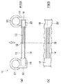
図1には、本発明の第1実施形態に係るインクジェット記録ヘッドが示されている。 FIG. 1 shows an ink jet recording head according to a first embodiment of the present invention.
図1に示すようにインクジェット記録ヘッド10は、内部にインク流路13を備え長さ方向略中央にノズル16を備えたインク流路部材12と、インク流路部材12を支持する梁部材14とが接合され、両端を保持部材18が支持する構造となっている。インク流路部材12は、インク吐出方向(図中白矢印)および逆方向に撓み可能であり、インクプール24から供給されインク流路13を通ってノズル16まで達したインクを慣性によって吐出方向にインク滴として吐出する。
As shown in FIG. 1, the ink
ここで用いられるインクは前述のように、媒体に着弾した際のインク滲み防止や、光学的な色濃度アップ、含水量低減による媒体の膨潤抑制/短時間乾燥、あるいは、そうした高品質インクをトータル設計するに当たり自由度が大きくとれる等の理由から、インク粘度の極めて高い、具体的には粘度10cpsを大きく上回るような(例えば50〜100cps)高粘度インクである。 As described above, the ink used here prevents ink bleeding when landing on the medium, increases the optical color density, suppresses swelling of the medium by reducing the water content / short-time drying, or totals such high-quality ink. The ink viscosity is extremely high, specifically, a high viscosity ink having a viscosity much higher than 10 cps (for example, 50 to 100 cps) due to a large degree of freedom in designing.
保持部材18は回転エンコーダ20に設けられたアーム22に固定され、回転エンコーダ20の回転中心からアーム22の長さ分だけオフセットされた位置にて両側から押圧され、あるいは曲げ方向に力が加えられインク吐出方向あるいは逆方向に梁部材14と接合したインク流路部材12を撓ませる。
The
保持部材18は図1(b)のように、保持部材18に複数のインク流路部材12が設けられた梯子状の構造であってもよい。
As shown in FIG. 1B, the
以下に実際の動作について説明する。 The actual operation will be described below.
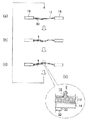
図2(a)のようにインク流路部材12が予めインク吐出方向(図中上)に撓みを持たせた状態であり、この状態での回転エンコーダ20の角度を0度とした場合、図2(b)のように回転エンコーダ20を矢印方向に、例えば0度〜プラス20度に回転させると、図2(c)、図2(d)のようにインク流路部材12はインク吐出方向に撓むのみであって、撓み量が最大となる図2(d)に至るまでインク流路部材12は常にインク吐出方向に凸であり続ける。
As shown in FIG. 2A, the ink
すなわち図2(a)から図2(d)まで変位するまでの間にインク流路部材12内部のインクに吐出方向への十分な加速度が加わらないため、インク滴としてノズル16から吐出されることはない(拡大図(e))。
That is, since sufficient acceleration in the ejection direction is not applied to the ink in the ink
一方、図3(a)に示すように、インク流路部材12が予めインク吐出方向(図中上)に撓みを持たせた状態であっても、逆回転方向(図中矢印方向)に回転エンコーダ20を、例えばマイナス5度に回転させると、インク流路部材12はインク吐出方向に凸から凹へと撓み方向が変化する(図3(b))。
On the other hand, as shown in FIG. 3A, the ink
次に図3(c)で、ここから再び回転エンコーダ20をマイナス5度〜プラス20度に正転(図中矢印方向)させるとインク流路部材12は回転エンコーダ20に近い方から次第に吐出方向(図中上)に凸へと撓み方向が変化する。この変化が両端から中央に近付くと、インク流路部材12(あるいは梁部材14)はある点で急峻な座屈反転を起こし、インク吐出方向(図中上)へと急激に変形する(図3(d))。
Next, in FIG. 3C, when the
インク流路部材12の長さ方向略中央にはノズル16が設けられているため、ノズル16まで達しているインクはこの座屈反転によるインク流路部材12の吐出方向への変形に伴い、ノズル16からインク滴2として吐出される。
Since the
この座屈反転による変形の速度は通常のアクチュエータなどによる変位と比較すれば非常に大きなものであり、本発明に採用した高粘度インクであっても十分にインク滴2として吐出することが可能である。
The deformation speed due to the buckling reversal is very large compared to the displacement caused by a normal actuator or the like, and even the high-viscosity ink employed in the present invention can be sufficiently discharged as the
図3(c)から図3(d)間のインク流路部材12(梁部材14)の変位とインク滴2の吐出の関係を図4に示す。
FIG. 4 shows the relationship between the displacement of the ink flow path member 12 (beam member 14) and the ejection of the
図4にはインク流路部材12が座屈反転を起こす直前からインク滴を吐出した直後までのインク流路部材12(梁部材14)の、ノズル16近傍の移動距離の時間による変化が示されている。
FIG. 4 shows a change with time of the moving distance of the ink flow path member 12 (beam member 14) in the vicinity of the
梁部材14が座屈反転を起こす直前(a’)はインク吐出方向に対して略静止状態なのでノズル16内のインクの液面に変動はない(a)。
Immediately before the
座屈反転が起こり始めると(b)、吐出方向に向けて急激に移動が始まるので、インクは慣性のため反対方向に押圧される形となり、ノズル16内のインク面は内側に凹となる。
When the buckling reversal starts to occur (b), the movement starts abruptly in the ejection direction, so that the ink is pressed in the opposite direction due to inertia, and the ink surface in the
このまま座屈反転による変形が続き、やがて梁部材14の変形が最大量となる手前で吐出方向への変位速度が落ち始める(c)。内部のインクは慣性のため等速度で吐出方向に進もうとするので、両者の速度差によりノズル16からインク滴2が突出し始める。
The deformation due to the buckling reversal continues as it is, and the displacement speed in the discharge direction starts to drop shortly before the deformation of the
梁部材14の変形が最大量となれば吐出方向への変位は停止するので(d’)、インク滴2のみがノズル16から突出し(d)、そのまま慣性に従ってインク滴2は吐出方向に撃ち出される(e)。
When the deformation of the
梁部材14の座屈反転による(a)〜(e)までの変位は極めて短い時間のあいだに起こるので、インクの粘性が高い本発明においても極めて良好な吐出性能が得られる。また、回転エンコーダ20は保持部材18の片方のみに設けてもインク滴2を吐出させることができる。
Since the displacements (a) to (e) due to the buckling inversion of the
具体的には、梁部材14は20μm厚で、長さ10mmのSUSプレート、流路部材12は50μm厚の樹脂フィルムを使用し、フォトリソ法で流路13をパタニングした後、梁部材14に積層接合する。流路部材12をパタニングした後の流路13の幅は50μmとした。ノズル16は25μm厚のポリイミドフィルムにレーザ加工を利用してφ30μmの孔を穿孔加工する。フィルム間はエポキシ系接着剤を用いて接合し、さらに剛体で製作した保持部材18にエポキシ系接着剤で接合したものを使用する。
Specifically, the
回転エンコーダ20と保持部材18は、回転エンコーダ20の回転中心から2.5mmオフセットさせた状態で接合し、インクを吐出させる時(梁座屈反転させる時)は回転エンコーダ20をマイナス5〜プラス20度に回転させる。この時、梁部材14の中央部は、インク吐出方向に約10m/sの速度で、1mm程移動する。グリセリンの混合比を増加させて50cps粘度に調整したインクは約25μm径、100cps粘度のインクは約20μm径のインク滴2としてノズル16から吐出する。
The
吐出実験では吐出周期は3Hzで駆動し、ストロボ法によってインク滴2を観察した。なお、回転エンコーダ20をマイナス5〜プラス30度回転に回転角度を増やすと、吐出するインク量は増大し、50cps粘度のインクは約30μm径、100cps粘度のインクは約25μm径のインク滴2として吐出した。
In the ejection experiment, the ejection cycle was driven at 3 Hz, and the
上記のように梁部材14の座屈曲がり反転を利用し、慣性でインク滴2を吐出する本方法は、従来技術では極めて困難であった50〜100cpsの高粘度インクを、加熱することなく吐出することが可能である。
As described above, the present method of ejecting the
また梁部材14に加える圧縮と回転の量、すなわち回転エンコーダ20の回転角度によって、インク滴2を吐出させる/吐出させない(座屈反転が起こるか/起こらないか)を制御することが可能であり、また梁部材14に加える圧縮と回転の量によってインクに加える慣性の大きさを可変でき、吐出するインク滴2の液量を変えることが可能となる。
Further, it is possible to control whether or not the
図5には、本発明の第2実施形態に係るインクジェット記録ヘッドが示されている。 FIG. 5 shows an ink jet recording head according to a second embodiment of the present invention.
図5に示すようにインクジェット記録ヘッド11は、内部にインク流路13を備え長さ方向略中央にノズル16を備えたインク流路部材12と、インク流路部材12を支持する梁部材14とが接合され、両端を保持部材18が支持する構造となっている。インク流路部材12は、インク吐出方向(図中白矢印)および逆方向に撓み可能であり、インクプール24から供給されインク流路13を通ってノズル16まで達したインクを慣性によって吐出方向にインク滴として吐出する。
As shown in FIG. 5, the ink
梁部材14にはピエゾ素子30が長さ方向の片側の略半分まで接合され、ピエゾ素子30によって梁部材14は曲げ方向に力が加えられインク吐出方向あるいは逆方向に梁部材14および梁部材14と接合したインク流路部材12を撓ませる。
A
ピエゾ素子30には個別電極32が形成されており、さらに信号線34が設けられている。信号線34は図示しないスイッチングICへ接続され、ON/OFF制御によってインク滴を吐出する/しないの制御を受ける。
An
梁部材14はピエゾ素子30の共通電極を兼ねており、一方でピエゾ素子30と接続され、他方で図示しない電源と接続されている。ピエゾ素子30、個別電極32、梁部材14を併せてアクチュエータ36として扱うことができる。
The
以下に実際の動作について説明する。 The actual operation will be described below.
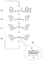
図6には、本発明の第2実施形態に係るインクジェット記録ヘッドの動作が示されている。 FIG. 6 shows the operation of the ink jet recording head according to the second embodiment of the present invention.
図6(a)のようにインク流路部材12(梁部材14等は省略)は予めインク吐出方向と逆(図中下)に撓みを持たせた状態で保持されている。
As shown in FIG. 6A, the ink flow path member 12 (the
ここでピエゾ素子30(アクチュエータ36を構成する他の要素は省略)が図示しないスイッチングICからの信号により駆動され、インク流路部材12をインク吐出方向(図中上)に撓ませる(図6(b))。
Here, the piezo element 30 (other elements constituting the
これによりインク流路部材12は保持部材18に保持された両端部から、インク吐出方向(図中上)に撓み始める。ノズル16の設けられた中央近傍はこの段階では反吐出方向(図中下)に凸すなわち吐出方向に凹となっている。
As a result, the ink
ピエゾ素子30による変形がさらに進み、インク流路部材12がインク吐出方向に座屈反転すると(図6(c))、インク流路部材12は保持部材18に近い方から次第に吐出方向(図中上)に凸へと撓み方向が変化する。この変化が両端から中央に近付くと、インク流路部材12(あるいは梁部材14)はある点で急峻な座屈反転を起こし、インク吐出方向(図中上)へと急激に変形する。
When the deformation by the
インク流路部材12の長さ方向略中央にはノズル16が設けられているため、ノズル16まで達しているインクはこの座屈反転によるインク流路部材12の吐出方向への変形に伴い、ノズル16からインク滴2として吐出される(図6(d))。
Since the
この座屈反転による変形の速度は通常のアクチュエータなどによる変位と比較すれば非常に大きなものであり、本発明に採用した高粘度インクであっても十分にインク滴2として吐出することが可能である。すなわち、アクチュエータ36による変位がゆっくりとしたものであっても、座屈反転による変形は十分に高速なので、高粘度のインクを使用していてもノズル16からインク滴2を吐出させることが可能となる。
The deformation speed due to the buckling reversal is very large compared to the displacement caused by a normal actuator or the like, and even the high-viscosity ink employed in the present invention can be sufficiently discharged as the
本実施形態においてはインク滴2を吐出する/しないの制御はピエゾ素子30への信号のON/OFFのみなので、単純な構造で高粘度のインクを吐出するインクジェット記録ヘッドとすることができる。
In the present embodiment, since control of whether or not to discharge the
図7には、本発明に係るインクジェット記録ヘッドを用いたインクジェット記録装置が示されている。 FIG. 7 shows an ink jet recording apparatus using the ink jet recording head according to the present invention.
図7に示すようにインクジェット記録装置50はヘッド支持部材54を備え、本発明のインクジェット記録ヘッド10ないしは11がヘッド支持部材54に保持される。ヘッド支持部材54はインクジェット記録ヘッド10ないしは11を保持し、かつインク吐出動作を妨げない構造となっている。ヘッド支持部材54の下には状記録媒体Pを載置し保持するテーブル52が設けられている。
As shown in FIG. 7, the
記録媒体Pをテーブル52にセットして、テーブル52を平面内でXおよびY方向(図中白矢印)に移動させるとともに、インクジェット記録ヘッド10ないしは11を駆動し、高粘度インクのインク滴2を吐出する。前述のように高粘度インクを使用しているので記録媒体Pに着弾した際のインク滴2の滲みは防止でき、高品質な記録が行える。
The recording medium P is set on the table 52, and the table 52 is moved in the X and Y directions (white arrows in the figure) in the plane, and the ink jet recording heads 10 or 11 are driven to eject
尚、本発明は、上記の実施の形態に限定されるものではない。 In addition, this invention is not limited to said embodiment.
例えば、上記実施の形態では、アクチュエータはピエゾ素子30と梁部材14とからなっているが、ピエゾ素子30のかわりに発熱抵抗体を利用し、熱膨張差で撓み変形するアクチュエータであっても良いし、静電力や磁力を利用したものであっても良い。或いは、その他の形態のアクチュエータであっても良い。
For example, in the above-described embodiment, the actuator includes the
また、上記実施の形態では、ノズル16とインク流路13は、それぞれ別々の樹脂フィルムに形成して接着接合したが、これに限定されない。例えば、ノズル、インク供給路を一体に形成しても良い。或いは、さらに梁部材14が一体の構造であっても良い。或いは、その他の形態であっても良い。
Moreover, in the said embodiment, although the
また、上記実施の形態では、インクジェット記録ヘッド10ないしは11を固定し、記録媒体Pを移動させながら記録を行うが、例えば、記録媒体Pを固定し、インクジェット記録ヘッド10ないしは11をキャリッジに搭載して搬送しながら記録を行っても良いし、双方を搬送しながら記録を行ってもよい。あるいは記録媒体Pをドラムに巻き付けて回転させる構造としてもよい。 In the above embodiment, the inkjet recording heads 10 or 11 are fixed and recording is performed while moving the recording medium P. For example, the recording medium P is fixed and the inkjet recording heads 10 or 11 are mounted on a carriage. Recording may be performed while being conveyed, or recording may be performed while conveying both. Alternatively, the recording medium P may be wound around a drum and rotated.
また、本明細書におけるインクジェット記録とは、記録紙上への文字や画像の記録に限定されるものではない。すなわち、記録媒体は紙に限定されるものでなく、また吐出する液体もインクに限定されるものではない。例えば、高分子フィルムやガラス上にインクを吐出してディスプレイ用カラーフィルターを作成したり、液状の半田を基板上に吐出して部品実装用のバンプを形成したりするなど、工業用的に用いられる液滴噴射装置全般に対して本発明を利用することが可能である。 In addition, the inkjet recording in the present specification is not limited to recording characters and images on recording paper. That is, the recording medium is not limited to paper, and the liquid to be ejected is not limited to ink. For example, industrial uses such as creating color filters for displays by discharging ink onto polymer films or glass, or forming bumps for component mounting by discharging liquid solder onto a substrate The present invention can be applied to all types of liquid droplet ejecting apparatuses.
10 インクジェット記録ヘッド
11 インクジェット記録ヘッド
12 インク流路部材
14 梁部材
16 ノズル
18 保持部材
20 回転エンコーダ
30 ピエゾ素子
50 インクジェット記録装置
DESCRIPTION OF
Claims (8)
前記インク流路部材と接合され一体に変形する梁部材と、
前記インク流路部材の長手方向略中央に設けられ、インク滴を吐出するノズルと、
を備え、
両側から押圧され両端を保持された前記梁部材を長手方向両側から押圧すると共にインク滴吐出方向に凹となるように弾性曲げ変形させた後、インク滴吐出方向に凸となるように弾性曲げ変形させて前記梁部材を座屈反転変形させ、
前記ノズル内部のインクに吐出方向の慣性を与え、インク滴として前記ノズルより吐出させる駆動手段を有することを特徴とするインクジェット記録ヘッド。 An ink flow path member having an ink flow path therein;
A beam member joined to the ink flow path member and deformed integrally;
A nozzle that is provided at substantially the center in the longitudinal direction of the ink flow path member and that discharges ink droplets;
With
The beam member pressed from both sides and held at both ends is pressed from both sides in the longitudinal direction and elastically bent and deformed to be concave in the ink droplet discharge direction , and then elastically bent and deformed to be convex in the ink droplet discharge direction. And buckling and reversing the beam member ,
Give the inertia of discharge direction to the ink inside the nozzle, the ink jet recording head characterized in that it comprises a driving means to eject from the nozzle as ink droplets.
前記梁部材がインク滴吐出方向に凹となるように回動したのち、前記梁部材がインク滴吐出方向に凸となるように座屈反転変形させ、前記ノズル近傍のインクに吐出方向の慣性を与えノズルより吐出させることを特徴とする請求項1に記載されたインクジェット記録ヘッド。 The driving means is rotatable while holding both ends or one end in the longitudinal direction of the beam member ,
After the beam member is rotated so as to be concave in the ink droplet ejection direction, the beam member is buckled and inverted so as to be convex in the ink droplet ejection direction, and the inertia in the ejection direction is applied to the ink near the nozzle. 2. The ink jet recording head according to claim 1, wherein the ink jet recording head is ejected from a feeding nozzle.
前記インク流路部材と接合され一体に変形する梁部材と、
前記インク流路部材の長手方向略中央に設けられ、インク滴を吐出するノズルと、
前記梁部材の両端を保持する保持部材と、
前記保持部材の一方または両方を支持し、回動して前記梁部材を圧縮する回転エンコーダと、
を備え、
前記保持部材は前記回転エンコーダの回転中心よりオフセットして支持されることにより、前記回転エンコーダの回転によって前記梁部材を長手方向両側から押圧すると共にインク滴吐出方向に凹となるように弾性曲げ変形させた後、インク滴吐出方向に凸となるように曲げ変形させて前記梁部材を座屈反転変形させ、
前記ノズル内部のインクに吐出方向の慣性を与え、インク滴として前記ノズルより吐出させることを特徴とするインクジェット記録ヘッド。 An ink flow path member having an ink flow path therein;
A beam member joined to the ink flow path member and deformed integrally;
A nozzle that is provided at substantially the center in the longitudinal direction of the ink flow path member and that discharges ink droplets;
A holding member for holding both ends of the beam member;
A rotary encoder that supports one or both of the holding members and rotates to compress the beam member ;
With
The holding member is supported by being offset from the rotation center of the rotary encoder so that the beam member is pressed from both sides in the longitudinal direction by the rotation of the rotary encoder and is elastically bent and deformed so as to be concave in the ink droplet discharge direction. After that, the beam member is bent and deformed so as to be convex in the ink droplet ejection direction, and the beam member is buckled and inverted ,
An ink jet recording head, wherein an ink in an ejection direction is given to ink inside the nozzle , and ink droplets are ejected from the nozzle.
前記インク流路部材の長手方向略中央に設けられ、インク滴を吐出するノズルと、
前記インク流路部材と接合され、もしくは前記インク流路部材を含み、予め長手方向両側から押圧されると共に、インク滴吐出方向と反対側に、インク滴吐出方向に凹となる方向に曲げて配置された梁部材と、
前記梁部材をインク滴吐出方向に凸となる方向に撓ませるアクチュエータと、
を備え、
前記アクチュエータはインク滴吐出方向に凹となった前記梁部材を、インク滴吐出方向に凸となる方向に座屈反転させ、前記インク流路内部のインクに吐出方向の慣性を与えることで前記ノズルからインク滴を吐出させることを特徴とするインクジェット記録ヘッド。 An ink flow path member having an ink flow path therein;
A nozzle that is provided at substantially the center in the longitudinal direction of the ink flow path member and that discharges ink droplets;
It is joined to the ink flow path member or includes the ink flow path member, is pressed from both sides in the longitudinal direction in advance, and is bent on the side opposite to the ink drop discharge direction so as to be concave in the ink drop discharge direction. Beam members,
An actuator that bends the beam member in a direction that is convex in the ink droplet ejection direction;
With
The actuator buckles and reverses the beam member , which is concave in the ink droplet ejection direction, in a direction that is convex in the ink droplet ejection direction, thereby giving the ink in the ink flow path inertia in the ejection direction. An ink jet recording head, wherein ink droplets are ejected from the ink jet recording head.
Priority Applications (3)
| Application Number | Priority Date | Filing Date | Title |
|---|---|---|---|
| JP2004322341A JP4466331B2 (en) | 2004-11-05 | 2004-11-05 | Inkjet recording head and inkjet recording apparatus |
| US11/115,054 US7566117B2 (en) | 2004-11-05 | 2005-04-26 | Inkjet recording head and inkjet recording device |
| US12/475,897 US8016391B2 (en) | 2004-11-05 | 2009-06-01 | Inkjet recording head and inkjet recording device |
Applications Claiming Priority (1)
| Application Number | Priority Date | Filing Date | Title |
|---|---|---|---|
| JP2004322341A JP4466331B2 (en) | 2004-11-05 | 2004-11-05 | Inkjet recording head and inkjet recording apparatus |
Publications (3)
| Publication Number | Publication Date |
|---|---|
| JP2006130780A JP2006130780A (en) | 2006-05-25 |
| JP2006130780A5 JP2006130780A5 (en) | 2007-12-20 |
| JP4466331B2 true JP4466331B2 (en) | 2010-05-26 |
Family
ID=36315871
Family Applications (1)
| Application Number | Title | Priority Date | Filing Date |
|---|---|---|---|
| JP2004322341A Expired - Fee Related JP4466331B2 (en) | 2004-11-05 | 2004-11-05 | Inkjet recording head and inkjet recording apparatus |
Country Status (2)
| Country | Link |
|---|---|
| US (2) | US7566117B2 (en) |
| JP (1) | JP4466331B2 (en) |
Families Citing this family (6)
| Publication number | Priority date | Publication date | Assignee | Title |
|---|---|---|---|---|
| JP4466331B2 (en) | 2004-11-05 | 2010-05-26 | 富士ゼロックス株式会社 | Inkjet recording head and inkjet recording apparatus |
| WO2009035016A1 (en) * | 2007-09-12 | 2009-03-19 | National University Corporation Nagoya Institute Of Technology | Explosive power generating device, and explosive power generating method |
| JP4548489B2 (en) | 2008-01-29 | 2010-09-22 | 富士ゼロックス株式会社 | Droplet discharge head |
| JP4636165B2 (en) | 2008-10-27 | 2011-02-23 | 富士ゼロックス株式会社 | Droplet discharge apparatus and image forming apparatus |
| WO2010064685A1 (en) * | 2008-12-04 | 2010-06-10 | 国立大学法人名古屋工業大学 | Instantaneous force generating device |
| JP2010143048A (en) | 2008-12-18 | 2010-07-01 | Fuji Xerox Co Ltd | Liquid droplet jetting head and liquid droplet jetting device |
Family Cites Families (28)
| Publication number | Priority date | Publication date | Assignee | Title |
|---|---|---|---|---|
| US4336544A (en) * | 1980-08-18 | 1982-06-22 | Hewlett-Packard Company | Method and apparatus for drop-on-demand ink jet printing |
| JPH08149253A (en) | 1994-09-22 | 1996-06-07 | Toshiba Corp | Ink jet recording device |
| US5835113A (en) | 1994-09-22 | 1998-11-10 | Kabushiki Kaisha Toshiba | Ink jet printing apparatus with controlled compression and ejection of colorants in liquid ink |
| JP3408059B2 (en) | 1995-09-22 | 2003-05-19 | キヤノン株式会社 | Liquid ejection head, liquid ejection device, and recovery method for liquid ejection device |
| EP0764528B8 (en) | 1995-09-22 | 2003-05-14 | Canon Kabushiki Kaisha | Liquid discharging method, liquid discharging head, liquid discharging apparatus, liquid container and head cartridge |
| JP3372758B2 (en) | 1996-06-07 | 2003-02-04 | キヤノン株式会社 | Liquid discharge method, liquid discharge head, liquid discharge device, liquid container, and head cartridge |
| JPH0985946A (en) * | 1995-09-25 | 1997-03-31 | Sharp Corp | Ink jet head and method of manufacturing the same |
| KR0185329B1 (en) * | 1996-03-27 | 1999-05-15 | 이형도 | Recording method using motor inertia of recording liquid |
| JPH10307381A (en) * | 1997-03-04 | 1998-11-17 | Fuji Photo Film Co Ltd | Liquid injector and production of liquid injector |
| US6079813A (en) | 1997-10-27 | 2000-06-27 | Raja Tuli | High speed thin film stressed membrane print head |
| GB9828476D0 (en) | 1998-12-24 | 1999-02-17 | Xaar Technology Ltd | Apparatus for depositing droplets of fluid |
| JP2001205814A (en) | 2000-01-28 | 2001-07-31 | Kyocera Corp | Inkjet head |
| JP2002234175A (en) | 2001-02-08 | 2002-08-20 | Canon Inc | Method and apparatus for preventing ink thickening in liquid ejecting apparatus, and color filter manufacturing apparatus |
| JP4565777B2 (en) | 2001-07-25 | 2010-10-20 | 旭化成ケミカルズ株式会社 | Acrylic polyisocyanate composition and sealing material containing the same |
| JP2003118114A (en) | 2001-10-15 | 2003-04-23 | Sharp Corp | Ink jet head and method of manufacturing the same |
| JP3781284B2 (en) | 2001-11-30 | 2006-05-31 | リコープリンティングシステムズ株式会社 | Inkjet recording head and recording apparatus therefor |
| JP2003220702A (en) | 2002-01-31 | 2003-08-05 | Konica Corp | Inkjet printer |
| US6644786B1 (en) | 2002-07-08 | 2003-11-11 | Eastman Kodak Company | Method of manufacturing a thermally actuated liquid control device |
| JP4466332B2 (en) | 2004-11-05 | 2010-05-26 | 富士ゼロックス株式会社 | Inkjet recording head and inkjet recording apparatus |
| JP4466333B2 (en) | 2004-11-05 | 2010-05-26 | 富士ゼロックス株式会社 | Inkjet recording head and inkjet recording apparatus |
| JP4539295B2 (en) | 2004-11-05 | 2010-09-08 | 富士ゼロックス株式会社 | Inkjet recording head and inkjet recording apparatus |
| JP4466331B2 (en) | 2004-11-05 | 2010-05-26 | 富士ゼロックス株式会社 | Inkjet recording head and inkjet recording apparatus |
| JP3925547B2 (en) | 2005-09-07 | 2007-06-06 | ブラザー工業株式会社 | Inkjet printer |
| JP4765601B2 (en) | 2005-12-14 | 2011-09-07 | 富士ゼロックス株式会社 | Droplet discharge head |
| JP2008030357A (en) | 2006-07-31 | 2008-02-14 | Fuji Xerox Co Ltd | Liquid droplet discharge head |
| JP2008207336A (en) | 2007-02-23 | 2008-09-11 | Fuji Xerox Co Ltd | Droplet discharg head |
| JP4636165B2 (en) * | 2008-10-27 | 2011-02-23 | 富士ゼロックス株式会社 | Droplet discharge apparatus and image forming apparatus |
| JP2010143048A (en) * | 2008-12-18 | 2010-07-01 | Fuji Xerox Co Ltd | Liquid droplet jetting head and liquid droplet jetting device |
-
2004
- 2004-11-05 JP JP2004322341A patent/JP4466331B2/en not_active Expired - Fee Related
-
2005
- 2005-04-26 US US11/115,054 patent/US7566117B2/en not_active Expired - Fee Related
-
2009
- 2009-06-01 US US12/475,897 patent/US8016391B2/en not_active Expired - Fee Related
Also Published As
| Publication number | Publication date |
|---|---|
| US8016391B2 (en) | 2011-09-13 |
| US20060098054A1 (en) | 2006-05-11 |
| US20090237466A1 (en) | 2009-09-24 |
| JP2006130780A (en) | 2006-05-25 |
| US7566117B2 (en) | 2009-07-28 |
Similar Documents
| Publication | Publication Date | Title |
|---|---|---|
| US8075120B2 (en) | Ink jet print head and ink jet printing apparatus | |
| JP2004001472A (en) | Printing system | |
| US8016391B2 (en) | Inkjet recording head and inkjet recording device | |
| US7631958B2 (en) | Ink-jet recording head and ink-jet recording device | |
| JP4636165B2 (en) | Droplet discharge apparatus and image forming apparatus | |
| JP4466333B2 (en) | Inkjet recording head and inkjet recording apparatus | |
| JP4466332B2 (en) | Inkjet recording head and inkjet recording apparatus | |
| JPH024516A (en) | Ink jet head | |
| JP4595669B2 (en) | Method for manufacturing droplet discharge head | |
| JP4307938B2 (en) | Electrostatic actuator, droplet discharge head, liquid cartridge, and image forming apparatus | |
| JP2003094641A (en) | Droplet discharge head and method of manufacturing the same | |
| JP2927265B2 (en) | Droplet ejector | |
| JPH10175316A (en) | Printer device | |
| JP4307808B2 (en) | Droplet discharge head and inkjet recording apparatus | |
| JP3716452B2 (en) | Inkjet printer head | |
| JP2008207336A (en) | Droplet discharg head | |
| JP2003165207A (en) | Ink jet recorder | |
| JP3297804B2 (en) | Printer device | |
| JP4970784B2 (en) | Joining apparatus, member joining method, and inkjet head manufacturing method | |
| JP2017061115A (en) | Droplet discharge member, image forming apparatus, and method for forming through hole for plate-like member | |
| US8029103B2 (en) | Liquid droplet ejection head for ejecting high viscosity liquid droplets, and liquid droplet ejection device | |
| JP2007160735A (en) | Liquid droplet ejection head | |
| JPH01306256A (en) | inkjet head | |
| JP2003051627A (en) | Piezoelectric driver and method of manufacturing the same, piezoelectric actuator, droplet discharge head, and ink jet recording apparatus | |
| JPH02301444A (en) | inkjet head |
Legal Events
| Date | Code | Title | Description |
|---|---|---|---|
| A521 | Request for written amendment filed |
Free format text: JAPANESE INTERMEDIATE CODE: A523 Effective date: 20071105 |
|
| A621 | Written request for application examination |
Free format text: JAPANESE INTERMEDIATE CODE: A621 Effective date: 20071105 |
|
| A977 | Report on retrieval |
Free format text: JAPANESE INTERMEDIATE CODE: A971007 Effective date: 20090824 |
|
| A131 | Notification of reasons for refusal |
Free format text: JAPANESE INTERMEDIATE CODE: A131 Effective date: 20090908 |
|
| A521 | Request for written amendment filed |
Free format text: JAPANESE INTERMEDIATE CODE: A523 Effective date: 20091109 |
|
| TRDD | Decision of grant or rejection written | ||
| A01 | Written decision to grant a patent or to grant a registration (utility model) |
Free format text: JAPANESE INTERMEDIATE CODE: A01 Effective date: 20100202 |
|
| A01 | Written decision to grant a patent or to grant a registration (utility model) |
Free format text: JAPANESE INTERMEDIATE CODE: A01 |
|
| A61 | First payment of annual fees (during grant procedure) |
Free format text: JAPANESE INTERMEDIATE CODE: A61 Effective date: 20100215 |
|
| R150 | Certificate of patent or registration of utility model |
Ref document number: 4466331 Country of ref document: JP Free format text: JAPANESE INTERMEDIATE CODE: R150 Free format text: JAPANESE INTERMEDIATE CODE: R150 |
|
| FPAY | Renewal fee payment (event date is renewal date of database) |
Free format text: PAYMENT UNTIL: 20130305 Year of fee payment: 3 |
|
| FPAY | Renewal fee payment (event date is renewal date of database) |
Free format text: PAYMENT UNTIL: 20130305 Year of fee payment: 3 |
|
| FPAY | Renewal fee payment (event date is renewal date of database) |
Free format text: PAYMENT UNTIL: 20140305 Year of fee payment: 4 |
|
| LAPS | Cancellation because of no payment of annual fees |