JP4465198B2 - Occlusion device and method - Google Patents
Occlusion device and method Download PDFInfo
- Publication number
- JP4465198B2 JP4465198B2 JP2004007106A JP2004007106A JP4465198B2 JP 4465198 B2 JP4465198 B2 JP 4465198B2 JP 2004007106 A JP2004007106 A JP 2004007106A JP 2004007106 A JP2004007106 A JP 2004007106A JP 4465198 B2 JP4465198 B2 JP 4465198B2
- Authority
- JP
- Japan
- Prior art keywords
- actuator
- slider
- filament
- housing
- sleeve
- Prior art date
- Legal status (The legal status is an assumption and is not a legal conclusion. Google has not performed a legal analysis and makes no representation as to the accuracy of the status listed.)
- Expired - Fee Related
Links
Images


Classifications
-
- A—HUMAN NECESSITIES
- A61—MEDICAL OR VETERINARY SCIENCE; HYGIENE
- A61B—DIAGNOSIS; SURGERY; IDENTIFICATION
- A61B17/00—Surgical instruments, devices or methods, e.g. tourniquets
- A61B17/0057—Implements for plugging an opening in the wall of a hollow or tubular organ, e.g. for sealing a vessel puncture or closing a cardiac septal defect
-
- A—HUMAN NECESSITIES
- A61—MEDICAL OR VETERINARY SCIENCE; HYGIENE
- A61B—DIAGNOSIS; SURGERY; IDENTIFICATION
- A61B5/00—Measuring for diagnostic purposes; Identification of persons
- A61B5/02—Detecting, measuring or recording pulse, heart rate, blood pressure or blood flow; Combined pulse/heart-rate/blood pressure determination; Evaluating a cardiovascular condition not otherwise provided for, e.g. using combinations of techniques provided for in this group with electrocardiography or electroauscultation; Heart catheters for measuring blood pressure
- A61B5/021—Measuring pressure in heart or blood vessels
- A61B5/0215—Measuring pressure in heart or blood vessels by means inserted into the body
-
- A—HUMAN NECESSITIES
- A61—MEDICAL OR VETERINARY SCIENCE; HYGIENE
- A61B—DIAGNOSIS; SURGERY; IDENTIFICATION
- A61B17/00—Surgical instruments, devices or methods, e.g. tourniquets
- A61B17/0057—Implements for plugging an opening in the wall of a hollow or tubular organ, e.g. for sealing a vessel puncture or closing a cardiac septal defect
- A61B2017/00637—Implements for plugging an opening in the wall of a hollow or tubular organ, e.g. for sealing a vessel puncture or closing a cardiac septal defect for sealing trocar wounds through abdominal wall
-
- A—HUMAN NECESSITIES
- A61—MEDICAL OR VETERINARY SCIENCE; HYGIENE
- A61B—DIAGNOSIS; SURGERY; IDENTIFICATION
- A61B17/00—Surgical instruments, devices or methods, e.g. tourniquets
- A61B17/0057—Implements for plugging an opening in the wall of a hollow or tubular organ, e.g. for sealing a vessel puncture or closing a cardiac septal defect
- A61B2017/00646—Type of implements
- A61B2017/00659—Type of implements located only on one side of the opening
-
- A—HUMAN NECESSITIES
- A61—MEDICAL OR VETERINARY SCIENCE; HYGIENE
- A61B—DIAGNOSIS; SURGERY; IDENTIFICATION
- A61B17/00—Surgical instruments, devices or methods, e.g. tourniquets
- A61B17/0057—Implements for plugging an opening in the wall of a hollow or tubular organ, e.g. for sealing a vessel puncture or closing a cardiac septal defect
- A61B2017/00672—Locating means therefor, e.g. bleed back lumen
-
- A—HUMAN NECESSITIES
- A61—MEDICAL OR VETERINARY SCIENCE; HYGIENE
- A61B—DIAGNOSIS; SURGERY; IDENTIFICATION
- A61B90/00—Instruments, implements or accessories specially adapted for surgery or diagnosis and not covered by any of the groups A61B1/00 - A61B50/00, e.g. for luxation treatment or for protecting wound edges
- A61B90/06—Measuring instruments not otherwise provided for
- A61B2090/064—Measuring instruments not otherwise provided for for measuring force, pressure or mechanical tension
-
- A—HUMAN NECESSITIES
- A61—MEDICAL OR VETERINARY SCIENCE; HYGIENE
- A61B—DIAGNOSIS; SURGERY; IDENTIFICATION
- A61B5/00—Measuring for diagnostic purposes; Identification of persons
- A61B5/02—Detecting, measuring or recording pulse, heart rate, blood pressure or blood flow; Combined pulse/heart-rate/blood pressure determination; Evaluating a cardiovascular condition not otherwise provided for, e.g. using combinations of techniques provided for in this group with electrocardiography or electroauscultation; Heart catheters for measuring blood pressure
- A61B5/021—Measuring pressure in heart or blood vessels
- A61B5/022—Measuring pressure in heart or blood vessels by applying pressure to close blood vessels, e.g. against the skin; Ophthalmodynamometers
- A61B5/023—Measuring pressure in heart or blood vessels by applying pressure to close blood vessels, e.g. against the skin; Ophthalmodynamometers the pressure transducers comprising a liquid column
-
- Y—GENERAL TAGGING OF NEW TECHNOLOGICAL DEVELOPMENTS; GENERAL TAGGING OF CROSS-SECTIONAL TECHNOLOGIES SPANNING OVER SEVERAL SECTIONS OF THE IPC; TECHNICAL SUBJECTS COVERED BY FORMER USPC CROSS-REFERENCE ART COLLECTIONS [XRACs] AND DIGESTS
- Y10—TECHNICAL SUBJECTS COVERED BY FORMER USPC
- Y10S—TECHNICAL SUBJECTS COVERED BY FORMER USPC CROSS-REFERENCE ART COLLECTIONS [XRACs] AND DIGESTS
- Y10S604/00—Surgery
- Y10S604/90—Telltale showing entry of blood into body inserted conduit
Abstract
Description
本発明は、一般に血管の壁における経皮的な穿刺孔を封止するための閉塞装置、より詳細には、経皮的な穿刺孔からの出血が防止されるように、それによって内部シールが血管の内側に配置され、固定部材が血管の外側に固定される閉塞装置および方法に関する。 The present invention generally relates to an occlusive device for sealing a percutaneous puncture hole in a blood vessel wall, and more particularly, to prevent bleeding from the percutaneous puncture hole thereby providing an internal seal. The present invention relates to an occluding device and a method that are arranged inside a blood vessel and in which a fixing member is fixed outside the blood vessel.
血管の経皮的な穿刺孔を封止するためのシステムは、血管の内壁に接触して位置決めされる内部シールと、フィラメントや縫合糸などによって内部シールと連結され且つ経皮的な穿刺孔を封止するように血管の外壁に接触して位置決めされる固定部材と、を備えて構成される。挿入期間において、内部シールは、血管内部に近づけられるように穿刺孔内に留まっているイントロデューサチューブ内に折り畳まれている。 A system for sealing a percutaneous puncture hole in a blood vessel includes an internal seal positioned in contact with the inner wall of the blood vessel, and a percutaneous puncture hole connected to the internal seal by a filament, suture, or the like. And a fixing member positioned in contact with the outer wall of the blood vessel so as to be sealed. During the insertion period, the inner seal is folded into an introducer tube that remains in the puncture hole so as to be closer to the inside of the blood vessel.
内部シールは、そのチューブを通して、イントロデューサの遠位端開口部から外へと押し出されることにより展開される。内部シールが血管内部で正しく確実に広がるように、内部シールが血管の内壁面に確実に固定されるように位置決めされる前に、その内部シールを血管壁の穿刺孔から少し離れた位置に配置する必要がある。内部シールが血管内に配置されると、イントロデューサは、その遠位端が血管の外側において穿刺孔に近接した状態となるように、穿刺孔から外へと抜き出される。この引き抜きの間、内部シールは血管壁上に穿刺孔を覆うように配置され、固定部材は、血管の外壁面と接触して固定されるまで、イントロデューサチューブを通して前方へと押し込まれる。上述したものとは異なった動作を実現する挿入用ツールが提案されているが、この挿入用ツールもまた同様に封止工程の前に内部シールおよび固定部材を収容している。 The inner seal is deployed by being pushed out of the introducer distal end opening through the tube. Place the inner seal slightly away from the puncture hole in the vessel wall before the inner seal is positioned to be securely fixed to the inner wall of the vessel so that the inner seal spreads correctly and reliably inside the vessel There is a need to. When the inner seal is placed within the blood vessel, the introducer is withdrawn out of the puncture hole such that its distal end is in close proximity to the puncture hole outside the blood vessel. During this withdrawal, the inner seal is placed over the vessel wall to cover the puncture hole and the fixation member is pushed forward through the introducer tube until it is fixed in contact with the outer wall of the vessel. Although an insertion tool has been proposed that realizes a different operation from that described above, this insertion tool also contains an internal seal and a securing member prior to the sealing step.
血管における経皮的な穿刺孔を封止するための装置および方法は、先行技術システムに結び付いた欠点に関して改良することができる。例えば、現行システムは無条件に固定部材のタンピングを許容し、挿入具の遠位端がタンピングの前に穿刺孔から引き戻されているという確認を提供せず、手技が不正確であれば固定部材が血管の内側に意図的ではなく位置決めされる可能性を引き起こす。 Devices and methods for sealing percutaneous puncture holes in blood vessels can be improved with respect to the disadvantages associated with prior art systems. For example, current systems allow unconditional tamping of the fixation member, do not provide confirmation that the distal end of the inserter has been pulled back from the puncture hole prior to tamping, and if the procedure is inaccurate, the fixation member Cause unintentional positioning inside the blood vessel.
現行システムにおけるもう1つの欠点は、内部シールを配置し、該内部シールを血管壁に接触させて据え付け、そして固定部材をタンピングするための現行ツールを取り扱うには、典型的には両手が必要とされることにある。 Another drawback with current systems is that typically two hands are required to place an internal seal, place the internal seal in contact with the vessel wall, and handle current tools for tamping the fixation member. It is to be done.
本発明の総合的目的は、それによって治療もしくは手術後に血管の壁における経皮的な穿刺孔を封止する際の適正な閉塞および取扱いの容易さがどちらも増強される閉塞装置および方法を提供することである。 The overall objective of the present invention is to provide an occlusion device and method whereby both proper occlusion and ease of handling are enhanced when sealing a percutaneous puncture hole in the vessel wall after treatment or surgery. It is to be.
1つの態様では、本発明の目的は、それによって固定部材が血管の内側に意図的ではなく位置決めされる可能性が排除される閉塞装置を提供することである。 In one aspect, an object of the present invention is to provide an occlusion device that eliminates the possibility of unintentionally positioning a fixation member inside a blood vessel.
また別の態様では、本発明の目的はそれによって固定部材をタンピングする前に内部シールを血管に接触させて据え付けることが保証される閉塞装置を提供することである。 In yet another aspect, an object of the present invention is to provide an occlusion device that ensures that an internal seal is installed in contact with a blood vessel prior to tamping the fixation member.
また別の態様では、本発明の目的はそれによって、血管の内側への内部シールの配置、内部シールを血管の内側に接触させて据え付けること、および穿刺孔を通しての出血が防止されるように固定部材をタンピングすることすべてを片手の操作で実施できる閉塞装置および方法を提供することである。 In yet another aspect, the object of the present invention is thereby secured to place an internal seal inside the blood vessel, place the internal seal in contact with the inside of the blood vessel, and prevent bleeding through the puncture hole It is an object of the present invention to provide an occluding device and method capable of performing all tamping of a member by one-hand operation.
本発明のこれらおよびその他の目的および態様は、請求項1に定義した閉塞装置、および請求項12に定義した方法によって満たされる。有益な実施形態は、下位の請求項に規定されている。
These and other objects and aspects of the invention are met by an occlusive device as defined in
手短には、本発明は、血管の壁における経皮的な穿刺孔を封止するための閉塞装置であって、血管の内側に内部シールを配置するために第1様式で動作可能であり、血管の外側で固定部材をタンピングするために第2様式で動作可動であるアクチュエータを有する挿入ツールを備えており、該アクチュエータが該内部シールおよび該固定部材を接続するフィラメント上へ作用する引張力へ反応して前記第2動作様式へセットされるように配置されている装置を提供する。 Briefly, the present invention is an occlusive device for sealing a percutaneous puncture hole in a vessel wall, operable in a first manner to place an internal seal inside the vessel, An insertion tool having an actuator that is movable in a second manner to tamping the fixation member outside the blood vessel, the actuator acting on the filament that connects the inner seal and the fixation member An apparatus is provided that is arranged to be responsively set to the second mode of operation.
好ましくは、該アクチュエータは、該フィラメント上に作用する引張力が該アクチュエータが前記第2動作様式へリセットされることを引き起こすまで、アクチュエータの作動を無効にするのに適合しているアクチュエータ機構によって制御される。 Preferably, the actuator is controlled by an actuator mechanism adapted to disable actuation of the actuator until a tensile force acting on the filament causes the actuator to be reset to the second mode of operation. Is done.
本明細書によると、血管の壁を通過する経皮的な穿刺孔を封止する方法が開示されるが、このとき固定部材のタンピングは内部シールおよび固定部材を接続するフィラメント上に作用する引張力を適用するステップを通して有効にされる。1つの好ましい実施形態では、固定部材のタンピングは、フィラメント上に作用する引張力が適用されるまで無効にされる。 According to the present specification, a method for sealing a percutaneous puncture hole passing through the wall of a blood vessel is disclosed, wherein the tamping of the fixation member is applied to the inner seal and the tension acting on the filament connecting the fixation member. Enabled through the step of applying power. In one preferred embodiment, tamping of the securing member is disabled until a tensile force acting on the filament is applied.
下記では、新規挿入ツールおよび方法を概略図により例示している図面を参照しながらより詳細に説明する。 In the following, the new insertion tool and method will be described in more detail with reference to the drawings, which are illustrated by schematic drawings.
血管における経皮的な穿刺孔を封止するための閉塞装置は、一般に図面において参照番号1を用いて言及する。図4〜10では、閉塞装置1は封止動作の手順ステップを例示している様々な動作位置で略図により示した。図11〜15では、閉塞装置1におけるアクチュエータ機構の構造および動作を実施例により例示して明らかにした。見やすくするために、図12および13は図14〜15の図面に関してより大きな縮尺で描出した。
An occlusion device for sealing a percutaneous puncture hole in a blood vessel is generally referred to with
方法
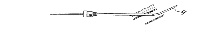
図1は、その遠位端部分は血管2の中に導入されており、その近位部分は患者の皮膚から外へ伸長しているイントロデューサ(先行技術)を示している。おそらく、手術は該イントロデューサを通して実施されており、そして今度は血管の壁3を通る穿刺孔が閉塞されなければならない。
Method FIG. 1 shows an introducer (prior art) whose distal end portion has been introduced into a blood vessel 2 and whose proximal portion extends out of the patient's skin. Perhaps surgery has been performed through the introducer, and now the puncture hole through the
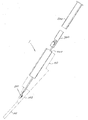
イントロデューサを本発明による閉塞装置と取り替えるためには、図2に示したようにガイドロッド4をイントロデューサに通して挿入することができる。
In order to replace the introducer with a closure device according to the invention, the
図3では、イントロデューサは抜き出されており、ガイドロッドだけが所定の位置に残されている。ガイドロッドの使用により達成される長所は、ガイドロッドの径がガイドワイヤの径より大きいことにあり、例えばこれは、動脈の場合には、動脈から流出する血液を減少させ、そしてそれにより手を使用した外部からの圧迫を回避できる。 In FIG. 3, the introducer has been extracted and only the guide rod is left in place. The advantage achieved by the use of guide rods is that the guide rod diameter is larger than the guide wire diameter, for example, in the case of arteries, this reduces blood flowing out of the arteries and The external pressure used can be avoided.
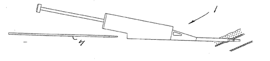
図4は、ガイドロッドに被せて進ませられた、本発明による閉塞装置1の図である。これは、既存のイントロデューサと接続するのに適合した挿入ツールとは対照的である。このため本閉塞装置は、例えば径もしくは長さのような血管内に事前に挿入されているイントロデューサの型とは無関係である。
FIG. 4 is a view of the
閉塞装置1の正確な位置決めが確立されると、図5および6に示したようにガイドロッドは抜き出される。
When the correct positioning of the
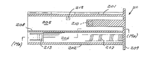
図6は、閉塞装置1のハウジングの前方部分の断面を略図により示している。この図面から、内部シールおよび固定部材が位置決めされている第1通路は、その中をガイドロッドが移動する第2通路と連絡しているのを見て取ることができる。ここで、第1および第2通路は、柔軟性であるガイドロッドが、それに通して内部シールが挿入される直線状通路と連絡する通路に通して挿入されるように、場所を交換させることが可能であることを言及しておかなければならない。さらに、どちらもわずかに屈曲している2つの通路を有することも考えられる。2つの通路は、さらにまた直線状通路に連絡することもできるが、これはY字形を有する構成を生じさせる。
FIG. 6 schematically shows a cross section of the front part of the housing of the
図7に示したように、アクチュエータは閉塞装置のハウジングの近位端内へ押し下げられている。該装置の遠位端が血管内に位置決めされると、ガイドロッドは抜き出され、そしてオペレータはアクチュエータをハウジング内に用意された端位置へ向かって押す。アクチュエータは第1相対位置ではタンピングチューブおよびプッシャーを運ぶスライド部材と操作可能に結び付けられており、プッシャーはその遠位端で取り外し可能に内部シールを有しており、血管の内側に配置されるべき閉塞装置から内部シールを押し出す。このステップで、アクチュエータ機構の第1動作様式が完了する。 As shown in FIG. 7, the actuator is pushed down into the proximal end of the closure device housing. When the distal end of the device is positioned within the blood vessel, the guide rod is withdrawn and the operator pushes the actuator toward the end position provided in the housing. The actuator is operably associated with a slide member carrying a tamping tube and a pusher in a first relative position, the pusher having a releasable internal seal at its distal end and should be located inside the blood vessel Push the inner seal out of the closure device. This step completes the first mode of operation of the actuator mechanism.
閉塞装置1のハウジング内に収容されているアクチュエータ機構の1つの実施形態は、図11〜15に略図により示したので、これらの図を参照しながら詳細に説明する。この機構の重要な機能は、アクチュエータがその端位置へ押し入れられているときには、フィラメント上の内部シールの後方に置かれている固定部材が意図せずに閉塞装置から押し出される可能性がないことにある。これにより、血管の内側にある固定部材の誤ったタンピングは防止される。この機構は、アクチュエータがハウジング内に押し入れられるときに該アクチュエータ上に作用するバイアス力を発生させるバネ部材を備える。アクチュエータがその端位置に達すると、スナップロック連結部が一時的にアクチュエータをこの端位置に停止させる。
One embodiment of the actuator mechanism housed in the housing of the
封止動作の次のステップでは、ハウジングは手作業で引き戻される、すなわちハウジングは内部シールが血管壁の内面と接触して穿刺孔の上方に据えられるまで近位方向に引っ張られ、他方閉塞装置の遠位端は同時に図8に示したように穿刺孔から引き戻される。 In the next step of the sealing operation, the housing is pulled back manually, i.e., the housing is pulled proximally until the inner seal is placed over the puncture hole in contact with the inner surface of the vessel wall, while the closure device The distal end is simultaneously withdrawn from the puncture hole as shown in FIG.
閉塞装置1の引き戻し中、内部シールに取付けられているその遠位端およびスライド部材に接続されているその近位端により拘束されるフィラメントによって引張力がかけられる。そこでフィラメントはスライド部材がその近位方向に移動するのを防止し、スライド部材がアクチュエータに対して移動させられることを引き起こす。スライド部材上に用意されたカム面によって、アクチュエータを停止させるスナップ連結部は引っ込みつつあるアクチュエータと静止しているスライド部材との間の相対移動に反応して解放される。スナップ連結部が解除されると、バイアス・バネはアクチュエータをタンピング位置に押し戻すので、アクチュエータは再びスライド部材と操作可能に結び付けられ、今度は第2相対位置になる。さらに、このハウジングの引き戻し中に、プッシャーの近位端はスライド部材との係合から引き離されるので、その後のアクチュエータの第2前進移動はプッシャーには何の影響も及ぼさない。タンピング動作では、アクチュエータはスライド部材、タンピングチューブおよび固定部材に作用する。
During withdrawal of the
図9は、アクチュエータの第2前進移動によって引き起こされる動作を示している。アクチュエータがハウジングにおける端位置に向かって2度目に押されると、アクチュエータは、図9に示したようにスライド部材を押し、スライド部材はタンピングチューブを通して固定部材を前方へ、そして血管壁の外面に接触させて固定位置へ前進させる。このステップは、アクチュエータ機構の第2動作様式を完了する。 FIG. 9 shows the motion caused by the second forward movement of the actuator. When the actuator is pushed a second time toward the end position in the housing, the actuator pushes the slide member as shown in FIG. 9, which slides through the tamping tube forward the fixation member and contacts the outer surface of the vessel wall To advance to a fixed position. This step completes the second mode of operation of the actuator mechanism.
フィラメントは固定部材の中を通っている。タンピングされた位置では、フィラメントはフィラメントの遠位部分から提供される摩擦係合によって固定部材を固定するが、前記部分は拡大した寸法もしくは径を有する。 The filament passes through the fixing member. In the tamped position, the filament secures the securing member by frictional engagement provided from the distal portion of the filament, which portion has an enlarged size or diameter.
該フィラメントの近位端は、スライド連結部を通してスライド部材に取付けられている。第1様式では、アクチュエータおよびスライド部材が内部シールを配置するために前方へ押されると、フィラメントはその遠位端によって内部シールをつかんでいるプッシャーによって張力がかけられる。第2様式では、アクチュエータおよびスライド部材が固定部材をタンピングするために前方へ押されると、プッシャーは動作を停止し、フィラメントはスライド部材に対して静止していて該フィラメントの張力を維持している部材によって拘束される。前進移動の最後に、該フィラメントの近位端は静止部材の作動によってスライド部材から解放される。 The proximal end of the filament is attached to the slide member through a slide connection. In the first mode, when the actuator and slide member are pushed forward to place the inner seal, the filament is tensioned by a pusher that is gripping the inner seal by its distal end. In the second mode, when the actuator and slide member are pushed forward to tamping the stationary member, the pusher stops operating and the filament is stationary relative to the slide member to maintain the filament tension. Restrained by the member. At the end of the forward movement, the proximal end of the filament is released from the slide member by actuation of the stationary member.
ここで、全封止手技を通して一人の人間が閉塞を片手で実施できることを述べておかなければならない。 It should be mentioned here that one person can perform the occlusion with one hand throughout the entire sealing procedure.
ハウジングおよびその関連コンポーネントはここで抜き出して廃棄することができ、それによって図10に示したように、内部シール、固定部材およびフィラメントだけが所定の位置に残される。フィラメントを切断すると封止手技が完了する。 The housing and its associated components can now be extracted and discarded, thereby leaving only the internal seal, securing member and filament in place, as shown in FIG. Cutting the filament completes the sealing procedure.
本装置の以下の説明からより完全に理解されるであろうが、本発明は、血管の壁における経皮的な穿刺孔を封止するための方法を開示するが、本方法は血管の内側に内部シールを配置するために第1様式で動作可能であり、そして血管の外側に固定部材をタンピングするために第2様式で動作可能であるアクチュエータを有する挿入ツールを提供するステップを備えており、このとき固定部材をタンピングするためのアクチュエータの動作は、アクチュエータを前記第2作動様式へセットするために、内部シールおよび固定部材を結合しているフィラメント上に作用する引張力を適用するステップを通して可能にされる。 As will be more fully understood from the following description of the device, the present invention discloses a method for sealing a percutaneous puncture hole in the wall of a blood vessel, the method being applied to the inside of the blood vessel. Providing an insertion tool having an actuator operable in a first manner to place an internal seal on the outer surface and operable in a second manner to tamping the fixation member outside the blood vessel. The operation of the actuator for tamping the fixing member at this time is through the step of applying a tensile force acting on the filaments connecting the inner seal and the fixing member to set the actuator to the second mode of operation. Made possible.
好ましくは、フィラメントに作用する引張力を適用するステップがアクチュエータを前記第2作動様式へリセットするまでは、内部シールを配置するためにアクチュエータを作動させるステップは固定部材をタンピングするためのアクチュエータの動作を無効にする。 Preferably, the step of actuating the actuator to position the inner seal is the operation of the actuator for tamping the securing member until the step of applying a tensile force acting on the filament resets the actuator to the second mode of operation. Disable.
本発明による閉塞装置の具現化
例示した実施形態についての以下の説明では、「遠位」は図11〜15の左側を意味し、「近位」は右側を意味する。同様に、「上」、「底部」、「水平」および「垂直」という表現は完全に図面に示した方向を意味しており、実践における閉塞装置の実際の方向を示すものではない。
Implementation of an Occlusion Device According to the Invention In the following description of the illustrated embodiment, “distal” means the left side of FIGS. 11-15 and “proximal” means the right side. Similarly, the expressions “top,” “bottom,” “horizontal,” and “vertical” refer to the directions shown in the drawings, and do not indicate the actual direction of the occlusion device in practice.
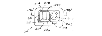
閉塞装置の主要構成部品
ここで図11を参照すると、閉塞装置1は主要構成部品として、ハウジング100(一点鎖線で描出した)、およびすべてがハウジング内に支持されているアクチュエータ200、スライダ300、スリーブ400、シールアッセンブリ500を備える。
Main Components of Occlusion Device Referring now to FIG. 11, the
基本的には、スリーブはハウジング内に入れ子式で収容されており、アクチュエータはスリーブ内に入れ子式で収容されており、シールアッセンブリはスライダへ操作可能に接続されており、そしてスライダはアクチュエータに動作可能に係合されている。スライダ300は、アクチュエータ200に対して第1および第2相対位置の間で長手移動するようにガイドされ、第2位置ではアクチュエータは該アクチュエータを移動させるようにスライダに動作可能に係合する。アクチュエータ200は、スリーブ400に対して伸長した保管もしくは空走位置から部分的に重複する動作可能な位置までの長手移動についてガイドされるが、アクチュエータはその位置からさらに第1様式では内部シールを配置するために、そして第2動作様式では固定部材をタンピングするために端位置へ前進させられる。スリーブ400はハウジング100内に収容されており、その中で伸長した空走位置から完全に挿入された動作位置へ長手移動のためにガイドされる。有益にも、ハウジング、スリーブおよびアクチュエータは共通長手軸の周囲に配置されている。ハウジング、スリーブおよびアクチュエータならびにスライダは、例えば円形のようないずれかの適切な断面形状であってよい、またはそれらは例えば本発明による閉塞装置の図示した実施形態のような直交区間を有していてもよい。1つのアッセンブリとして、これらの構成部品は例えば内部シール、フィラメントおよび固定部材のような封止構成部品を挿入するためのツールを提供する。
Basically, the sleeve is telescoped within the housing, the actuator is telescoping within the sleeve, the seal assembly is operably connected to the slider, and the slider operates on the actuator Engaged as possible. The
ハウジング
ハウジング100は、前方ハウス部分102を介してハウジングの遠位端に接続している(挿入の方向で見たときに)挿入チューブ101と結び付けられている。挿入チューブ101およびハウス部分102は、ハウジングの一体成形部分であってよい。穿刺孔を通してその遠位端から挿入されると、挿入チューブ101は血管と前方ハウス部分102内に形成された第1および第2通路とを連絡するが、それらの通路の一方は血管内への配置中に挿入チューブを制御するガイドを受け入れるように設計されており、そして他方の通路は穿刺孔を封止する際に内部シールおよび固定部材を挿入するために設計されている。これらの通路は挿入チューブ101内へ合流する。有益にも、ハウジングは、ハウジング100/挿入チューブ101の遠位端を介して、該血管との液体連絡が確立されていることの検証を提供する表示手段を備えて形成される。
Housing The
シールアッセンブリ
図12を参照すると、シールアッセンブリ500は内部シール501および固定部材502を備えており、内部シールは固定部材の中を通っている縫合糸もしくはフィラメント503の遠位端に固定されている。固定部材502は、フィラメント上でタンピングされた(前進した)位置にある固定部材との摩擦係合を提供する増加した断面寸法を有するフィラメントの端部分504の近位側上で内部シールの後方に間隔をあけて置かれている。使用準備が整った状態では、内部シールおよび固定部材はどちらも前方ハウス部分102内に封入されている(図11に略図で示した)。
Seal Assembly Referring to FIG. 12,
フィラメント503は、プッシャー506と一緒にタンピングチューブ505の中を通っている。フィラメントおよびプッシャーはどちらもタンピングチューブの遠位端を超えて伸長しており、プッシャーはその遠位端で内部シール501を取り外し可能につかんでおり、そして固定部材502はタンピングチューブ505の遠位端の外側でフィラメント上に自由に動けるように支持されている。さらに、フィラメントおよびプッシャーはどちらもタンピングチューブの近位端から伸びている。フィラメント503、プッシャー506およびタンピングチューブ505の近位端は、図13−1〜13−4を参照して以下で説明するように、すべてがスライダ300内に支持されている。
The
スライダ
図示した実施形態では、スライダ300はそれと一緒に長手移動するためにアクチュエータ200内に収容できるような寸法にされ、それに対して長手移動するためにアクチュエータ内でガイドされる直交区間を有する細長い四方体である。図13−3〜13−4では、スライダ300は、水平上面303を水平底面304と接続し対向する垂直側壁301、302を有している。好ましくは、これらの壁を接続する長手辺縁は、アクチュエータ内でひっかかることなく容易にスライド移動させるために面取りされている。
Slider In the illustrated embodiment, the
タンピングチューブ505は、スライダの遠位端へ連絡している。タンピングチューブの近位端はスライダ300の遠位端で口を開けている凹所305内に受け入れられている。
A tamping
スライダ300の1つの側壁301では、凹所305は外部へ向かって側方へ開いており、該開口部は側壁301を介して凹所305をすき間307と接続するスロット306を形成している。側壁301の内部上では、スロット306はすき間307からスライダ300の近位端へ直線的に進行する。対応するスロット306’は対向する側壁302の内側上に形成される。スロット306、306’は、プッシャー506を受け入れてガイドする寸法にされており、プッシャーの近位端507は2つのスロット306、306’とスライド係合するためにスライダ300の内側を超えて伸びるように横方向に曲げられている。
In one
フィラメントはスライド連結部を介してスライダと取り外し可能に接続されている。フィラメント503の近位端は、反対側の壁302から切り離されて、長手棒308の周囲に巻き付けることによってスライダ内に拘束されている。バー308はスライダの遠位部分から伸長して、スライダの近位部分にある自由端で終了する。フィラメントは、わずかな張力下で棒308からスライダ300の内側を超え、すき間307を通ってスロット306内へ、そしてさらにタンピングチューブ505を通ってプッシャー506の遠位端内で支持されている内部シールまで走っている。
The filament is detachably connected to the slider via a slide connecting portion. The proximal end of the
フィラメントの張力はプッシャーによって与えられる。プッシャーの近位端507における横部分はスライダ300の底部304から立ち上がるラッチ310内に形成されたシート309内に拘束されており、そしてプッシャーの遠位端はフィラメントの遠位端へ取付けられている内部シールへ取り外し可能に接続されている。プッシャーの長さは、プッシャーの近位端がラッチ310によって拘束させられ、そしてフィラメントの近位端がバー308の周囲に巻き付けられている限りフィラメントを引っ張るのに十分なプッシャーのわずかな偏りを提供するためのフィラメントの長さに対して決定される。
Filament tension is provided by a pusher. The lateral portion at the
シート309は、スライダ300の底部に向かって押すことのできるラッチ310によって、プッシャーとのスナップロック連結を提供する。ラッチを押すと、プッシャーがシート309から解放されてスライダ300の近位端へ向かってスロット306、306’内へ自由にスライドすることを引き起こす。
The
スライダ300の近位端に面しているヒール311は、スライダの底部から立ち上がっているアーム312の末端に形成されている。ラッチ310と同様に、アーム312はスライダ300の底部に向かって押すことができる。しかし、これより先で説明する理由から、アーム312は柔軟性であり、図面に示した動作位置へ戻ることができる。有益にも、ラッチ310およびアーム312はどちらも柔軟性で、例えばポリマー材料のような合成材料から製造されたスライダと一体成形されている。
A
ラッチ310およびアーム312はどちらも、アクチュエータ200内で静止しているカムと相互作用する斜面313、314を備えて形成されている。
Both the
組み立てると、図14−1〜14−5を参照しながら詳細に説明するように、カムはスライダ300の内部に受け入れられる開いた上面303を通って伸びている。
When assembled, the cam extends through an open
アクチュエータ
図示した図14−1〜14−5の実施形態では、アクチュエータ200はそれと一緒に長手移動するためにスライダ300を受け入れるような寸法にされ、それに対して長手移動するために該スライダをガイドする、直交区間を有する細長い中空の四方体である。アクチュエータ200は、水平上面203を水平底面204と接続し対向する垂直側壁201、202を備えて形成されている。好ましくは、壁を接続している長手辺縁は、スリーブ400内でひっかかることなくスライド移動を容易にするために面取りされている。
Actuator In the illustrated embodiment of FIGS. 14-1 to 14-5, the
図14−1〜14−3を参照すると、アクチュエータ200はその片側に沿って一緒にヒンジ結合されたツーピース要素である。アクチュエータ本体を閉塞するために、スナップロック係合を反対側の上に形成することができる。アクチュエータ200の内部は、スライダ300を受け入れるように形成された第1長手チャンバ205と、そして圧縮バネ207を受け入れるように形成された第2長手チャンバ206に分かれている(図14−2、14−3における一点鎖線を通して略図により示されている)。長手仕切壁208によって分離された両方のチャンバは、アクチュエータ200の遠位端に開口している。それの近位端は閉塞しており、プッシュボタン209を有している。
Referring to FIGS. 14-1 to 14-3, the
上面203の内部から離れると、カム210はチャンバ205内へ到達する。組み立てた位置では、カム210はスライダ300の開いた上面を通して、ある深さへ受け入れられるが、このときカム210はスライダがアクチュエータに対して移動させられると連続して斜面313および314に係合して押すように操作可能である、すなわちまず最初にラッチ310、そしてその後アーム312を押す。
When leaving the interior of the
図7および14−4における内部シールを配置するための第1作動様式では、スライダ300の近位端はアクチュエータ200の近位プッシュボタン端に接しており、したがってアクチュエータはスライダをスライダとアクチュエータとの間の第1相対位置で前方へ(遠位端へ向かって)押す。
In the first mode of operation for placing the internal seal in FIGS. 7 and 14-4, the proximal end of the
図9および14−5における固定部材をタンピングするための第2動作様式では、カム210はヒール311に係合するので、したがってアクチュエータはアクチュエータに対して第2の前進位置にスライダを押す。
In the second mode of operation for tamping the securing member in FIGS. 9 and 14-5, the
アクチュエータに対して前記第1位置から前記第2位置へのスライダ300の移動は、穿刺孔の上方に内部シールを位置決めするため、そしてハウジング/挿入チューブの遠位端を引き戻すためにハウジングを引き戻すと引張力が適用されることによって引き起こされる。引き戻し中に、スライダはそれと一緒にフィラメントを通して接続されている内部シールに対して停止したままとなる。ハウジングおよびスリーブを介してアクチュエータへ適用され、そしてフィラメントに作用して、それによって運ばれる引張力は、バイアス・バネ式アクチュエータの射出を引き起こし、そしてシート309からプッシャーを解放するためにカムを移動させることによって押されるラッチ310上の斜面へカム210を係合させる。アクチュエータカム210のその後の移動は、プッシャーに、プッシャーの横部分507がカム210上に形成されているフック211によって捕まれるにようにさせる。次に、カム210は、カムをヒール311の近位側へ移動させるために押されているアーム312上の斜面に係合する。アーム312は柔軟性であるため、アームはその最初の位置へ復帰するが、このときヒール311がカムの経路内へ突き出るので、そこでスライダをアクチュエータに対して第2の前進位置に静止させる。同時に、プッシャーの近位端は、スライダ壁の内側に形成されたガイドスロット306、306’から離れる。プッシャーがシート309との係合から解放されてカム−フックフォーメーション210、211によって後方へ引っ張られると、同時にプッシャーの遠位端は内部シールから引き離される。プッシャーの近位端がスライダ壁内のスロットを離れると、プッシャーの遠位端もまたタンピングチューブの遠位端内へ完全に引き戻される。
Movement of the
したがってアクチュエータとスライダの間の相対移動はフィラメント上に作用する引張力によって開始され、そしてその後下記で説明するように圧縮バネによって駆動される。 Thus, the relative movement between the actuator and the slider is initiated by a tensile force acting on the filament and then driven by a compression spring as will be described below.
スリーブ
図15−1〜15−3を参照すると、スリーブ400はスリーブに対する長手移動のためにアクチュエータ200を受け入れてガイドするような寸法にされた直交区間を有する細長い中空の四方体である。スリーブ400は、水平上面403を水平底面404と接続し対向する垂直側壁401、402を用いて形成されている。好ましくは、これらの壁を接続している長手辺縁は、スリーブ400を収容しているハウジング100に対してひっかかることのない自由な移動を容易にするために面取りされている。
Sleeve Referring to FIGS. 15-1 to 15-3, the
スリーブ400はアクチュエータを受け入れる開いた近位端を有しており、そしてスリーブの遠位端は端壁405によって閉塞されている。端壁を通る開口部406はハウジング100の前方部分102を通る通路と連絡しており、閉塞装置の挿入チューブ内へシールアッセンブリをガイドする。
The
ロッド407はスリーブを通り、端壁405から近位端へ向かって長手方向に突き出ている。このアッセンブリでは、ロッド407は、スリーブの端壁405とアクチュエータの近位もしくはプッシュボタン端209との間で機能し、そしてアクチュエータがスリーブ内へ押されると圧縮されるバネ207、このケースではコイルバネ207を支持するためにアクチュエータのチャンバ206内へ突き出ている。
The
同様に端壁405から突き出ているのは、ロッドと平行に走っていて、組み立てられた位置ではスライダ300の開いた内部と整列しているビーム408である。ビーム408は、実質的にアクチュエータ200の上面203における壁厚に対応して、上面403の内部からすき間をあけて走っている。ビーム408は、スリーブの底面に向けて圧縮可能であるラッチ409を有する。ラッチ409は、アクチュエータが内部シールを配置するためにスリーブ内へ十分に押されるとアクチュエータの上面203内に用意されたスロット212(図14aを参照)に係合するために柔軟性である。スロット212およびラッチ409はスナップロック連結を提供するが、ラッチ409はとりあえず下記で説明するように、スリーブの端壁405にその遠位端を接触させてアクチュエータを保持するために操作可能である。アクチュエータが遠位方向へそれ以上移動することが防止される明確な停止位置で第1動作様式を終了させるこのアクチュエータの端位置では、ビームの近位端410は、前記第1相対位置でアクチュエータによって係合されるスライダ300の遠位端に受け入れられる。
Also protruding from the
アクチュエータのリセット
ラッチ409は、ラッチから外向きおよび垂直に偏っており、スライダの遠位端に用意されたカム315によって操作可能に係合されるようにアライメントされている斜面411と結び付けられている(図13−1〜13−4を参照)。挿入ツールが引き戻されると、スライダ(静止したままになっている)上のカム315が斜面411に作用してラッチ409を押し、ラッチ409はその後スロット212から解放される。したがってアクチュエータ200はバネ207の作用によって射出されるスナップロック連結部212、409から解放され、バネはスリーブに対して、および静止しているスライダに対してアクチュエータを近位方向へ駆動させる。
The
バネの作用はプッシャーの解放を引き起こし、そしてそこからアクチュエータが作動可能であり、固定部材をタンピングすることが可能な位置へアクチュエータをリセットする。アクチュエータのバネ作動射出は、スリーブ上に用意されたスロット412と係合しているアクチュエータの遠位端部分に用意された柔軟性のラッチ213を通して限定される。ラッチ213は、スロットの遠位縁に向いている斜面、およびスロット413の近位縁に係合している横面を備えて形成されている。この拘束された位置から、アクチュエータ200は遠位方向に押されるように操作可能であるが、しかし近位方向へのそれ以上の移動は防止される。スリーブ内へアクチュエータを押し込むと、スライダ300はアクチュエータの移動に引き込まれ、アクチュエータのカム210はアクチュエータに対して第2の前進位置にあるスライダのヒール311に係合する。
The action of the spring causes the pusher to be released, from which the actuator is operable and resets the actuator to a position where the securing member can be tamped. Spring actuation of the actuator is limited through a
フィラメントの解放
アクチュエータが第2動作様式でこの位置からスリーブ内に押されると、スライダはアクチュエータの前方もしくは遠位位置へ前進させられる。この移動では、スリーブ上に静止しているビーム408がスライダの内部を通って長手方向に移動する。バー308の周囲に巻き付けられていてスライダの内部を横断しているフィラメントは、その後ビームの近位端410によって捕捉され、それによってバー308の近位端へ向かってスライドすることが引き起こされる。したがって、フィラメントは静止したままとなるが、アクチュエータ、スライダおよびタンピングチューブは、固定部材をフィラメントの遠位部分との摩擦係合へ滑り入れさせるために前進させられる。タンピング動作の終了時に、フィラメントループは棒の近位端に到達し、そこからビーム408の作用によって滑り落ち、そこでフィラメントはスライダから解放される。明らかに、タンピング動作に関係するすべての構造は、固定部材がフィラメント上の最終位置に到達し、血管壁の外側に対してタンピングされるとフィラメントの解放を許容するように構造的長さおよび移動の長さに関して寸法が決められている。フィラメントの解放は、タンピング作動を終了させ、そして挿入ツールを患者から抜き出すことができる。
Filament Release When the actuator is pushed into the sleeve from this position in a second mode of operation, the slider is advanced to a forward or distal position of the actuator. In this movement, the
ここに例示した実施形態は、本発明を実現するための1つの例である。詳細な構造および構成部品のデザインに対する修飾は、クレームによって定義された基本的解決策を変更せずとも可能である。 The embodiment illustrated here is one example for realizing the present invention. Modifications to the detailed structure and component design are possible without changing the basic solution defined by the claims.
1つの一体成形アクチュエータの代わりに、例えば内部シールを配置するために第1アクチュエータを適合させ、そして固定部材をタンピングするために第2アクチュエータを適合させることができる。このような場合には、スライダは、フィラメントを通しての引張力動作に反応して第1アクチュエータから解放されて第2アクチュエータと係合し、この間に同時に第2アクチュエータが動作状態にセットされるように配置される。同様に、例示したように共通長手軸の周囲に配置される代わりに、アクチュエータ、スリーブおよびスライダは、第2動作様式がフィラメント上に作用するように適用される引張力に反応して可能になるまでは第1動作様式がその場所からタンピングチューブおよび固定部材がそれ以上遠位方向へ移動するのが防止される明確な停止位置で終了することが保証される限り、あらゆる考えられる形状であってよい。 Instead of one integral actuator, for example, the first actuator can be adapted to place an internal seal and the second actuator can be adapted to tamping the securing member. In such a case, the slider is released from the first actuator and engaged with the second actuator in response to the pulling force action through the filament so that the second actuator is simultaneously set to the operating state during this time. Be placed. Similarly, instead of being arranged around a common longitudinal axis as illustrated, the actuator, sleeve and slider are enabled in response to a tensile force applied so that the second mode of action acts on the filament. Until the first mode of operation is guaranteed to end in a well-defined stop position where it is prevented from further distal movement of the tamping tube and securing member from that location, all possible shapes Good.
したがって、新規閉塞装置の中心的機能は、第1様式にあるアクチュエータが内部シールを配置するために動作可能であり、そしてその後第2様式へリセットされるが、このときアクチュエータが固定部材をタンピングするために作動可能であることにある。アクチュエータのリセットは、内部シールと固定部材とを接続するフィラメント上に作用する引張力を適用することによって達成される。そこで、内部シールの配置、第2動作様式の実現および固定部材のタンピングは、すべてを片手操作で実施できる。同様に、血管内での固定部材の間違った位置決めは、アクチュエータが好ましくはフィラメント上への引張力の作用がアクチュエータを動作可能な状態へリセットすることを引き起こすまで無効になっていることによって防止される。したがって経皮的な穿刺孔の適正な閉塞および取扱いの容易さは、どちらも本発明によって開示した閉塞装置を通して増強される。 Thus, the central function of the new occlusion device is that the actuator in the first mode is operable to place the internal seal and then reset to the second mode, at which time the actuator tamps the securing member In order to be operable. The resetting of the actuator is accomplished by applying a tensile force acting on the filament connecting the inner seal and the securing member. Therefore, the arrangement of the internal seal, the realization of the second operation mode, and the tamping of the fixing member can all be performed by one-hand operation. Similarly, incorrect positioning of the fixation member within the vessel is prevented by the actuator being disabled until the action of the tensile force on the filament preferably causes the actuator to reset to an operable state. The Thus, proper occlusion and ease of handling of percutaneous puncture holes are both enhanced through the occlusion device disclosed by the present invention.
1 閉塞装置
2 血管
3 血管の壁
4 ガイドロッド
100 ハウジング
101 挿入チューブ
102 前方ハウス部分
200 アクチュエータ
203 アクチュエータ上面
205,206 長手チャンバ
207 バネ
208 長手仕切壁
209 プッシュボタン
210 カム
211 フック
212,306,306’ ,412,413 スロット
300 スライダ
301,302,401,402 垂直側壁
303,403 水平上面
304,404 水平底面
305 凹所
307 すき間
308 バー
309 シート
310,409 ラッチ
311 ヒール
312 アーム
313,314 斜面
315 カム
400 スリーブ
405 スリーブの端壁
406 開口部
407 ロッド
408 ビーム
410 ビームの近位端
411 斜面
500 シールアッセンブリ
501 内部シール
502 固定部材
503 フィラメント
504 フィラメントの端部分
505 タンピングチューブ
506 プッシャー
507 プッシャーの近位端
DESCRIPTION OF
Claims (12)
ハウジング(100)と、第1様式および第2様式で動作可能であるアクチュエータ(200)と、を有する挿入ツール(1)を備え、
前記アクチュエータ(200)は、前記第1様式において、血管の内側に内部シール(501)を配置するように構成されると共に、前記第2様式において、血管の外側に固定部材(502)をタンピングするように構成され、
前記アクチュエータは、前記内部シールと前記固定部材とを接続するフィラメント上に作用する引張力に反応して前記第2様式にセットされるように配置され、
前記アクチュエータ(200)は、前記第1様式および前記第2様式の両方において、ユーザにより接触され且つ操作され、
前記固定部材(502)は、前記アクチュエータ(200)が前記ハウジング(100)に対して移動することにより、前記血管の外側にタンピングされる、閉塞装置。 An occluding device for sealing a percutaneous puncture hole in a blood vessel wall,
It includes a housing (100), an actuator (200) operable in a first mode and second modes, the insertion tool (1) having,
The actuator (200) is configured to place an internal seal (501) inside the blood vessel in the first manner and tamping a fixation member (502) outside the blood vessel in the second manner. Configured as
The actuator is arranged to be set in the second mode in response to a tensile force acting on a filament connecting the inner seal and the fixing member ;
The actuator (200) is contacted and operated by a user in both the first mode and the second mode;
The occlusion device , wherein the fixation member (502) is tamped outside the blood vessel as the actuator (200) moves relative to the housing (100) .
前記ハウジング(100)は、前記シールアッセンブリをガイドするためにその遠位端によって位置決めされるように配置され、
前記シールアッセンブリは、
前記フィラメント(503)の遠位端に取り付けられた前記内部シール(501)と、
該フィラメント上に前記内部シールから間隔をあけて移動可能に置かれている前記固定部材(502)と、
前記ハウジング内にガイドされ、その遠位端が取り外し可能に前記内部シールと接続されているプッシャー(506)と、
前記ハウジング内にガイドされるタンピングチューブ(505)であって、前記フィラメントが該タンピングチューブ内を通って前記タンピングチューブの遠位端の外側へと前記固定部材と前記内部シールとを運ぶ、タンピングチューブ(505)と、
を備え、
前記閉塞装置はさらに、前記内部シールを配置するために前記プッシャーを駆動するように動作可能な第1様式で前記アクチュエータ(200)を制御するアクチュエータ機構(300,400)を備え、
前記フィラメント上に作用する引張力によって前記アクチュエータが、前記固定部材をタンピングするために前記タンピングチューブを駆動するように動作可能な第2様式へとリセットされるまで、前記アクチュエータ機構は、前記アクチュエータを無効にさせるのに適合している、請求項1または2に記載の閉塞装置。 A seal assembly,
It said housing (100) is arranged to be positioned by its distal end to guide the seal assembly,
The seal assembly is
The inner seal attached to the distal end of the filament (503) and (501),
The securing member (502) movably placed on the filament at a distance from the inner seal;
A pusher (506) guided in the housing, the distal end of which is removably connected to the inner seal;
A tamping tube (505) guided in the housing, wherein the filament carries the securing member and the internal seal through the tamping tube and out of the distal end of the tamping tube. (505)
With
The closure device further comprises an actuator mechanism (300, 400) for controlling the actuator (200) in a first manner operable to drive the pusher to position the inner seal;
Until the actuator is reset to a second mode operable to drive the tamping tube to tamping the securing member by a tensile force acting on the filament, the actuator mechanism causes the actuator to 3. An occlusion device according to claim 1 or 2 adapted to be disabled.
前記スリーブは前記ハウジング内に入れ子式で受け入れられており、
前記アクチュエータは前記スリーブ内に入れ子式で受け入れられており、
前記スライダ(300)は前記アクチュエータ(200)内に収容されており、
前記シールアッセンブリは前記フィラメント(503)を介して動作可能に前記スライダと接続されており、
前記スライダは、前記内部シールを配置するために前記アクチュエータによって移動させられる第1相対位置で、前記アクチュエータに係合されており、前記フィラメント(503)上に作用する引張力により、前記アクチュエータに対して第2相対位置へ移動させることができ、これにより前記スライダは前記固定部材をタンピングするために前記アクチュエータにより移動させられるように前記アクチュエータに係合される、請求項3に記載の閉塞装置。 A sleeve (400); and a slider (300), the sleeve being received in a nested manner in the housing;
The actuator is received nested in the sleeve;
The slider (300) is housed in the actuator (200),
The seal assembly is operatively connected to the slider via the filament (503) ;
The slider is in the first relative position to be moved by the actuator to position the inner seal, which is engaged with the actuator, by pulling force acting on the filament (503), to said actuator Te can be moved to a second relative position, whereby said slider is engaged to the actuator to be moved by the actuator for tamping the fixing member occlusive device of claim 3.
前記スリーブと前記アクチュエータとの間で作用する圧縮バネ(207)は、前記アクチュエータを前記第2様式へと追いやるのに有効である、請求項6に記載の閉塞装置。 The cam formation (315) on the slider is arranged to release a snap lock connection (212, 409) between the actuator (200) and the sleeve (400),
A closure device according to claim 6 , wherein a compression spring (207) acting between the sleeve and the actuator is effective to drive the actuator into the second mode.
前記ハウジングの相互連結している前方部分(102)は、各々前記シールアッセンブリ(500)のためおよびガイド部材のための別個の通路を有しており、前記通路が前記挿入チューブ内へ合流している、請求項1〜10のいずれか一つに記載の閉塞装置。 The insertion tool (1) has a housing (100) whose distal end is associated with the insertion tube (101);
The interconnecting forward portions (102) of the housing each have separate passages for the seal assembly (500) and for the guide member, the passages joining into the insertion tube. The occlusion device according to any one of claims 1 to 10 .
Applications Claiming Priority (1)
| Application Number | Priority Date | Filing Date | Title |
|---|---|---|---|
| US43980003P | 2003-01-14 | 2003-01-14 |
Publications (2)
| Publication Number | Publication Date |
|---|---|
| JP2004216157A JP2004216157A (en) | 2004-08-05 |
| JP4465198B2 true JP4465198B2 (en) | 2010-05-19 |
Family
ID=32595349
Family Applications (2)
| Application Number | Title | Priority Date | Filing Date |
|---|---|---|---|
| JP2004007106A Expired - Fee Related JP4465198B2 (en) | 2003-01-14 | 2004-01-14 | Occlusion device and method |
| JP2004007105A Pending JP2004216156A (en) | 2003-01-14 | 2004-01-14 | Device for visually indicating blood pressure |
Family Applications After (1)
| Application Number | Title | Priority Date | Filing Date |
|---|---|---|---|
| JP2004007105A Pending JP2004216156A (en) | 2003-01-14 | 2004-01-14 | Device for visually indicating blood pressure |
Country Status (6)
| Country | Link |
|---|---|
| US (3) | US8118831B2 (en) |
| EP (1) | EP1440656A3 (en) |
| JP (2) | JP4465198B2 (en) |
| AU (2) | AU2004200122A1 (en) |
| DE (1) | DE602004021981D1 (en) |
| ES (1) | ES2329363T3 (en) |
Families Citing this family (57)
| Publication number | Priority date | Publication date | Assignee | Title |
|---|---|---|---|---|
| US7662161B2 (en) | 1999-09-13 | 2010-02-16 | Rex Medical, L.P | Vascular hole closure device |
| US6896692B2 (en) | 2000-12-14 | 2005-05-24 | Ensure Medical, Inc. | Plug with collet and apparatus and method for delivering such plugs |
| US6846319B2 (en) | 2000-12-14 | 2005-01-25 | Core Medical, Inc. | Devices for sealing openings through tissue and apparatus and methods for delivering them |
| US8083768B2 (en) | 2000-12-14 | 2011-12-27 | Ensure Medical, Inc. | Vascular plug having composite construction |
| US6890343B2 (en) | 2000-12-14 | 2005-05-10 | Ensure Medical, Inc. | Plug with detachable guidewire element and methods for use |
| US6623509B2 (en) * | 2000-12-14 | 2003-09-23 | Core Medical, Inc. | Apparatus and methods for sealing vascular punctures |
| US8992567B1 (en) | 2001-04-24 | 2015-03-31 | Cardiovascular Technologies Inc. | Compressible, deformable, or deflectable tissue closure devices and method of manufacture |
| US20110144661A1 (en) * | 2001-04-24 | 2011-06-16 | Houser Russell A | Tissue closure devices, device and systems for delivery, kits and methods therefor |
| US8961541B2 (en) | 2007-12-03 | 2015-02-24 | Cardio Vascular Technologies Inc. | Vascular closure devices, systems, and methods of use |
| US20080109030A1 (en) | 2001-04-24 | 2008-05-08 | Houser Russell A | Arteriotomy closure devices and techniques |
| EP1440656A3 (en) * | 2003-01-14 | 2004-10-06 | Radi Medical Systems Ab | Device for visually indicating a blood pressure |
| US7850654B2 (en) * | 2003-04-24 | 2010-12-14 | St. Jude Medical Puerto Rico B.V. | Device and method for positioning a closure device |
| US8852229B2 (en) | 2003-10-17 | 2014-10-07 | Cordis Corporation | Locator and closure device and method of use |
| US7361183B2 (en) * | 2003-10-17 | 2008-04-22 | Ensure Medical, Inc. | Locator and delivery device and method of use |
| US7713283B2 (en) * | 2005-04-11 | 2010-05-11 | St. Jude Medical Puerto Rico, Llc | Tissue puncture closure device with magazine fed tamping system |
| US8926654B2 (en) * | 2005-05-04 | 2015-01-06 | Cordis Corporation | Locator and closure device and method of use |
| US8088144B2 (en) | 2005-05-04 | 2012-01-03 | Ensure Medical, Inc. | Locator and closure device and method of use |
| US7837705B2 (en) * | 2005-05-17 | 2010-11-23 | St. Jude Medical Puerto Rico Llc | Tissue puncture closure system with retractable sheath |
| JP4802324B2 (en) * | 2006-02-22 | 2011-10-26 | 国立大学法人 名古屋工業大学 | Pulse wave measurement device for pulse diagnosis analysis |
| US20070282181A1 (en) * | 2006-06-01 | 2007-12-06 | Carol Findlay | Visual medical sensor indicator |
| WO2008033964A2 (en) | 2006-09-13 | 2008-03-20 | Accessclosure, Inc. | Apparatus for sealing a vascular puncture |
| US8858591B2 (en) | 2007-10-31 | 2014-10-14 | Radi Medical Systems Ab | Method and device for sealing a puncture hole in a bodily organ |
| US20090112234A1 (en) * | 2007-10-31 | 2009-04-30 | Lawrence Crainich | Reloadable laparoscopic fastener deploying device for use in a gastric volume reduction procedure |
| US8652166B2 (en) | 2007-11-30 | 2014-02-18 | Radi Medical Systems Ab | Insertion tool for a medical closure device |
| US20110029013A1 (en) | 2008-02-15 | 2011-02-03 | Mcguckin James F | Vascular Hole Closure Device |
| US8070772B2 (en) | 2008-02-15 | 2011-12-06 | Rex Medical, L.P. | Vascular hole closure device |
| US8920462B2 (en) | 2008-02-15 | 2014-12-30 | Rex Medical, L.P. | Vascular hole closure device |
| US8491629B2 (en) | 2008-02-15 | 2013-07-23 | Rex Medical | Vascular hole closure delivery device |
| US8920463B2 (en) * | 2008-02-15 | 2014-12-30 | Rex Medical, L.P. | Vascular hole closure device |
| US9226738B2 (en) * | 2008-02-15 | 2016-01-05 | Rex Medical, L.P. | Vascular hole closure delivery device |
| EP3001954B1 (en) * | 2008-11-12 | 2018-01-10 | Access Closure, Inc. | Apparatus for sealing a vascular puncture |
| US8292918B2 (en) | 2009-02-20 | 2012-10-23 | Boston Scientific Scimed, Inc. | Composite plug for arteriotomy closure and method of use |
| US8317824B2 (en) | 2009-02-20 | 2012-11-27 | Boston Scientific Scimed, Inc. | Tissue puncture closure device |
| US9913634B2 (en) | 2009-02-20 | 2018-03-13 | Boston Scientific Scimed, Inc. | Locking element for vascular closure device |
| US8529598B2 (en) | 2009-02-20 | 2013-09-10 | Boston Scientific Scimed, Inc. | Tissue puncture closure device |
| US8052914B2 (en) | 2009-02-20 | 2011-11-08 | Boston Scientific Scimed, Inc. | Modified plug for arteriotomy closure |
| US8375553B2 (en) | 2009-02-20 | 2013-02-19 | Boston Scientific Scimed, Inc. | Locking element for vascular closure device |
| KR101773205B1 (en) * | 2009-04-09 | 2017-09-12 | 카디오배스큘러 테크놀러지스 인코포레이티드 | Tissue closure devices, device and systems for delivery, kits and methods therefor |
| US9028466B2 (en) * | 2009-06-08 | 2015-05-12 | St. Jude Medical Coordination Center Bvba | Adapter for use in connecting to a first percutaneous introducer |
| EP2496153A1 (en) * | 2009-11-03 | 2012-09-12 | St. Jude Medical Systems AB | Introducer access assembly |
| US8469944B2 (en) * | 2009-11-03 | 2013-06-25 | Radi Medical Systems Ab | Introducer access assembly |
| WO2011100547A2 (en) | 2010-02-11 | 2011-08-18 | Boston Scientific Scimed, Inc. | Automatic vascular closure deployment devices and methods |
| US8727570B2 (en) * | 2010-02-16 | 2014-05-20 | Martin Professional A/S | Belt tensioning means integrated into illumination device shell part |
| JP5615030B2 (en) * | 2010-04-30 | 2014-10-29 | 日本コヴィディエン株式会社 | Syringe and catheter set having the syringe |
| US8597340B2 (en) | 2010-09-17 | 2013-12-03 | Boston Scientific Scimed, Inc. | Torque mechanism actuated bioabsorbable vascular closure device |
| US8758402B2 (en) | 2010-12-17 | 2014-06-24 | Boston Scientific Scimed, Inc. | Tissue puncture closure device |
| CA2836790C (en) | 2011-05-31 | 2019-04-23 | Desmond Adler | Multimodal imaging system, apparatus, and methods |
| WO2013019840A1 (en) | 2011-08-03 | 2013-02-07 | Lightlab Imaging, Inc. | Systems, methods and apparatus for determining a fractional flow reserve |
| US10485524B2 (en) | 2011-10-25 | 2019-11-26 | Essential Medical, Inc. | Instrument and methods for surgically closing percutaneous punctures |
| WO2014150154A1 (en) | 2013-03-15 | 2014-09-25 | Essential Medical, Inc. | Vascular closure devices and methods of use |
| US10154835B2 (en) | 2013-05-09 | 2018-12-18 | Essential Medical, Inc. | Vascular closure device with conforming plug member |
| EP3086716B1 (en) | 2013-12-23 | 2021-04-07 | Arrow International LLC | Vascular closure device |
| ES2883138T3 (en) | 2014-04-04 | 2021-12-07 | St Jude Medical Systems Ab | Intravascular Pressure and Flow Data Diagnostic System |
| US10555727B2 (en) * | 2015-06-26 | 2020-02-11 | Essential Medical, Inc. | Vascular closure device with removable guide member |
| FR3059961B1 (en) * | 2016-12-13 | 2019-10-18 | Valeo Systemes D'essuyage | ADAPTER FOR WIPER BLADE |
| US11504105B2 (en) | 2019-01-25 | 2022-11-22 | Rex Medical L.P. | Vascular hole closure device |
| JPWO2021192964A1 (en) * | 2020-03-23 | 2021-09-30 |
Family Cites Families (53)
| Publication number | Priority date | Publication date | Assignee | Title |
|---|---|---|---|---|
| US2748769A (en) * | 1953-02-24 | 1956-06-05 | Huber Jennie | Hypodermic needle |
| US3062202A (en) * | 1960-03-25 | 1962-11-06 | Hyman Chester | Body fluid pressure measuring device |
| US3730168A (en) * | 1970-09-10 | 1973-05-01 | Kendall & Co | Manometer |
| US3760627A (en) * | 1971-12-13 | 1973-09-25 | Richline Co Inc | Rivet gun |
| JPS50139588A (en) * | 1974-04-23 | 1975-11-07 | ||
| USRE34021E (en) * | 1985-11-18 | 1992-08-04 | Abbott Laboratories | Percutaneous fixation of hollow organs |
| US4767408A (en) * | 1986-03-24 | 1988-08-30 | Taut, Inc. | Flashback structure |
| US4796612A (en) * | 1986-08-06 | 1989-01-10 | Reese Hewitt W | Bone clamp and method |
| USRE34866E (en) * | 1987-02-17 | 1995-02-21 | Kensey Nash Corporation | Device for sealing percutaneous puncture in a vessel |
| US4894052A (en) * | 1988-08-22 | 1990-01-16 | Becton, Dickinson And Company | Flash detection in an over the needle catheter with a restricted needle bore |
| US5098433A (en) * | 1989-04-12 | 1992-03-24 | Yosef Freedland | Winged compression bolt orthopedic fastener |
| US5620461A (en) * | 1989-05-29 | 1997-04-15 | Muijs Van De Moer; Wouter M. | Sealing device |
| NL8901350A (en) * | 1989-05-29 | 1990-12-17 | Wouter Matthijs Muijs Van De M | CLOSURE ASSEMBLY. |
| JPH0634780B2 (en) | 1989-11-30 | 1994-05-11 | テルモ株式会社 | Blood pressure waveform correction device |
| US5021059A (en) * | 1990-05-07 | 1991-06-04 | Kensey Nash Corporation | Plug device with pulley for sealing punctures in tissue and methods of use |
| US6325789B1 (en) * | 1990-12-27 | 2001-12-04 | Datascope Investment Corporation | Device and method for sealing puncture wounds |
| CA2078530A1 (en) * | 1991-09-23 | 1993-03-24 | Jay Erlebacher | Percutaneous arterial puncture seal device and insertion tool therefore |
| US5676689A (en) * | 1991-11-08 | 1997-10-14 | Kensey Nash Corporation | Hemostatic puncture closure system including vessel location device and method of use |
| US5282827A (en) * | 1991-11-08 | 1994-02-01 | Kensey Nash Corporation | Hemostatic puncture closure system and method of use |
| US5411520A (en) * | 1991-11-08 | 1995-05-02 | Kensey Nash Corporation | Hemostatic vessel puncture closure system utilizing a plug located within the puncture tract spaced from the vessel, and method of use |
| US5250049A (en) * | 1992-01-10 | 1993-10-05 | Michael Roger H | Bone and tissue connectors |
| US5295969A (en) * | 1992-04-27 | 1994-03-22 | Cathco, Inc. | Vascular access device with air-tight blood containment capability |
| US5246426A (en) * | 1992-06-17 | 1993-09-21 | Arrow International Investment Corp. | Catheterization system |
| US5342393A (en) * | 1992-08-27 | 1994-08-30 | Duke University | Method and device for vascular repair |
| US5306254A (en) * | 1992-10-01 | 1994-04-26 | Kensey Nash Corporation | Vessel position locating device and method of use |
| US5433053A (en) * | 1993-05-20 | 1995-07-18 | Bechtel Corporation | Barbed tee fastener |
| US5431639A (en) * | 1993-08-12 | 1995-07-11 | Boston Scientific Corporation | Treating wounds caused by medical procedures |
| US5501671A (en) * | 1993-11-02 | 1996-03-26 | Novoste Corporation | Vascular blood containment device |
| US5545178A (en) * | 1994-04-29 | 1996-08-13 | Kensey Nash Corporation | System for closing a percutaneous puncture formed by a trocar to prevent tissue at the puncture from herniating |
| US5531759A (en) * | 1994-04-29 | 1996-07-02 | Kensey Nash Corporation | System for closing a percutaneous puncture formed by a trocar to prevent tissue at the puncture from herniating |
| US5549633A (en) * | 1994-08-24 | 1996-08-27 | Kensey Nash Corporation | Apparatus and methods of use for preventing blood seepage at a percutaneous puncture site |
| US5666710A (en) * | 1995-04-20 | 1997-09-16 | Emhart Inc. | Blind rivet setting system and method for setting a blind rivet then verifying the correctness of the set |
| US5722990A (en) * | 1995-11-08 | 1998-03-03 | Sugar Surgical Technologies, Inc. | Tissue grasping device |
| DE19603887C2 (en) * | 1996-02-03 | 1998-07-02 | Lerch Karl Dieter | Arrangement for fixing a piece of bone that has been removed from the skull capsule for the purpose of the surgical intervention to the remaining skull leg |
| US5853422A (en) * | 1996-03-22 | 1998-12-29 | Scimed Life Systems, Inc. | Apparatus and method for closing a septal defect |
| US5662681A (en) * | 1996-04-23 | 1997-09-02 | Kensey Nash Corporation | Self locking closure for sealing percutaneous punctures |
| US6491714B1 (en) * | 1996-05-03 | 2002-12-10 | William F. Bennett | Surgical tissue repair and attachment apparatus and method |
| US5861003A (en) * | 1996-10-23 | 1999-01-19 | The Cleveland Clinic Foundation | Apparatus and method for occluding a defect or aperture within body surface |
| US5855559A (en) * | 1997-02-14 | 1999-01-05 | Tricardia, Inc. | Hemostatic agent delivery device having built-in pressure sensor |
| EP0858776A3 (en) * | 1997-02-14 | 2000-01-12 | Tricardia, L.L.C. | Hemostatic agent delivery device having built-in pressure sensor |
| US6193670B1 (en) * | 1997-02-14 | 2001-02-27 | Tricardia, Llc | Hemostatic agent delivery device having built-in pressure sensor |
| US6045551A (en) * | 1998-02-06 | 2000-04-04 | Bonutti; Peter M. | Bone suture |
| DE19817762A1 (en) * | 1998-04-21 | 1999-10-28 | Dietmar Enk | Appts for intravasal blood measurement |
| US6689070B2 (en) * | 1998-12-28 | 2004-02-10 | Cytyc Health Corporation | Devices, methods and systems for collecting material from a breast duct |
| EP1196092A1 (en) | 1999-06-18 | 2002-04-17 | Radi Medical Systems Ab | A tool, a sealing device, a system and a method for closing a wound |
| US6379363B1 (en) * | 1999-09-24 | 2002-04-30 | Walter Lorenz Surgical, Inc. | Method and apparatus for reattachment of a cranial flap using a cranial clamp |
| US6794485B2 (en) * | 2000-10-27 | 2004-09-21 | Poly-Med, Inc. | Amorphous polymeric polyaxial initiators and compliant crystalline copolymers therefrom |
| US6508828B1 (en) * | 2000-11-03 | 2003-01-21 | Radi Medical Systems Ab | Sealing device and wound closure device |
| US6524277B1 (en) * | 2000-12-29 | 2003-02-25 | Ethicon, Inc. | Method and apparatus for an intravascular device showing flashback |
| ES2223679T3 (en) * | 2001-05-09 | 2005-03-01 | Radi Medical Systems Ab | SHUTTER OF AN ARTERIAL PERFORATION. |
| ATE287665T1 (en) | 2001-06-15 | 2005-02-15 | Radi Medical Systems | STUFFING UNIT |
| JP4159805B2 (en) * | 2001-06-15 | 2008-10-01 | ラディ・メディカル・システムズ・アクチェボラーグ | Pushing mechanism for closing method |
| EP1440656A3 (en) * | 2003-01-14 | 2004-10-06 | Radi Medical Systems Ab | Device for visually indicating a blood pressure |
-
2004
- 2004-01-09 EP EP04000323A patent/EP1440656A3/en not_active Withdrawn
- 2004-01-12 ES ES04100076T patent/ES2329363T3/en not_active Expired - Lifetime
- 2004-01-12 DE DE602004021981T patent/DE602004021981D1/en not_active Expired - Lifetime
- 2004-01-13 AU AU2004200122A patent/AU2004200122A1/en not_active Abandoned
- 2004-01-13 AU AU2004200121A patent/AU2004200121B2/en not_active Ceased
- 2004-01-14 US US10/756,764 patent/US8118831B2/en not_active Expired - Fee Related
- 2004-01-14 JP JP2004007106A patent/JP4465198B2/en not_active Expired - Fee Related
- 2004-01-14 US US10/756,765 patent/US7654963B2/en not_active Expired - Fee Related
- 2004-01-14 JP JP2004007105A patent/JP2004216156A/en active Pending
-
2012
- 2012-01-10 US US13/347,188 patent/US8512372B2/en not_active Expired - Fee Related
Also Published As
| Publication number | Publication date |
|---|---|
| AU2004200121B2 (en) | 2009-01-15 |
| US8512372B2 (en) | 2013-08-20 |
| JP2004216156A (en) | 2004-08-05 |
| US20040204741A1 (en) | 2004-10-14 |
| US20040204654A1 (en) | 2004-10-14 |
| AU2004200122A1 (en) | 2004-07-29 |
| EP1440656A3 (en) | 2004-10-06 |
| EP1440656A2 (en) | 2004-07-28 |
| AU2004200121A1 (en) | 2004-07-29 |
| US20120109192A1 (en) | 2012-05-03 |
| DE602004021981D1 (en) | 2009-08-27 |
| US7654963B2 (en) | 2010-02-02 |
| US8118831B2 (en) | 2012-02-21 |
| ES2329363T3 (en) | 2009-11-25 |
| JP2004216157A (en) | 2004-08-05 |
Similar Documents
| Publication | Publication Date | Title |
|---|---|---|
| JP4465198B2 (en) | Occlusion device and method | |
| RU2597771C2 (en) | Improved clip advancer | |
| US20190282784A1 (en) | Safety needle system operable with a medical device | |
| US11141166B2 (en) | Clip treatment tool | |
| US5972005A (en) | Wound closure assembly and method of use | |
| US6258102B1 (en) | Reusable laproscopic retrieval mechanism | |
| JP4136020B2 (en) | Medical ligature | |
| US20060190015A1 (en) | Clipping device | |
| EP1440661B1 (en) | Closure device | |
| JP4351531B2 (en) | Wound suture device | |
| US20010002437A1 (en) | Reusable laparoscopic retrieval pouchtitle | |
| BRPI0604715B1 (en) | SURGICAL CLIP APPLICATOR | |
| JP5371610B2 (en) | Suture device | |
| JP2022087253A (en) | Hemostasis reloadable clipping device with sleeve engagement | |
| JPH10512771A (en) | Universal handle for medical instruments | |
| JP2009502419A (en) | Tissue puncture closure device with coiled automatic tamping system | |
| JPH04227248A (en) | Vital tissue sampler | |
| EP1266626B1 (en) | Tamping mechanism | |
| CN109862832A (en) | Blood vessel plugging device with the locked component for packer | |
| JP2009523515A (en) | Kit and method for assembling an applicator for inserting an implant | |
| US11889997B2 (en) | Biopsy instrument having outer needle-locking member | |
| CA3178489A1 (en) | Apparatus and methods for loading suture | |
| JP2013534170A (en) | Clutch release mechanism for vascular closure device | |
| JP2974785B2 (en) | Retractable safety penetrator with safety probe | |
| WO2014121112A1 (en) | Endoscopic injection needle device |
Legal Events
| Date | Code | Title | Description |
|---|---|---|---|
| A621 | Written request for application examination |
Free format text: JAPANESE INTERMEDIATE CODE: A621 Effective date: 20061013 |
|
| A131 | Notification of reasons for refusal |
Free format text: JAPANESE INTERMEDIATE CODE: A131 Effective date: 20091006 |
|
| A521 | Request for written amendment filed |
Free format text: JAPANESE INTERMEDIATE CODE: A523 Effective date: 20091219 |
|
| TRDD | Decision of grant or rejection written | ||
| A01 | Written decision to grant a patent or to grant a registration (utility model) |
Free format text: JAPANESE INTERMEDIATE CODE: A01 Effective date: 20100202 |
|
| A01 | Written decision to grant a patent or to grant a registration (utility model) |
Free format text: JAPANESE INTERMEDIATE CODE: A01 |
|
| A61 | First payment of annual fees (during grant procedure) |
Free format text: JAPANESE INTERMEDIATE CODE: A61 Effective date: 20100222 |
|
| FPAY | Renewal fee payment (event date is renewal date of database) |
Free format text: PAYMENT UNTIL: 20130226 Year of fee payment: 3 |
|
| R150 | Certificate of patent or registration of utility model |
Free format text: JAPANESE INTERMEDIATE CODE: R150 |
|
| FPAY | Renewal fee payment (event date is renewal date of database) |
Free format text: PAYMENT UNTIL: 20130226 Year of fee payment: 3 |
|
| FPAY | Renewal fee payment (event date is renewal date of database) |
Free format text: PAYMENT UNTIL: 20140226 Year of fee payment: 4 |
|
| R250 | Receipt of annual fees |
Free format text: JAPANESE INTERMEDIATE CODE: R250 |
|
| R250 | Receipt of annual fees |
Free format text: JAPANESE INTERMEDIATE CODE: R250 |
|
| S111 | Request for change of ownership or part of ownership |
Free format text: JAPANESE INTERMEDIATE CODE: R313113 |
|
| S531 | Written request for registration of change of domicile |
Free format text: JAPANESE INTERMEDIATE CODE: R313531 |
|
| S533 | Written request for registration of change of name |
Free format text: JAPANESE INTERMEDIATE CODE: R313533 |
|
| R350 | Written notification of registration of transfer |
Free format text: JAPANESE INTERMEDIATE CODE: R350 |
|
| LAPS | Cancellation because of no payment of annual fees |