JP4464654B2 - Microscope equipment - Google Patents
Microscope equipment Download PDFInfo
- Publication number
- JP4464654B2 JP4464654B2 JP2003374634A JP2003374634A JP4464654B2 JP 4464654 B2 JP4464654 B2 JP 4464654B2 JP 2003374634 A JP2003374634 A JP 2003374634A JP 2003374634 A JP2003374634 A JP 2003374634A JP 4464654 B2 JP4464654 B2 JP 4464654B2
- Authority
- JP
- Japan
- Prior art keywords
- light
- optical element
- light source
- specimen
- optical path
- Prior art date
- Legal status (The legal status is an assumption and is not a legal conclusion. Google has not performed a legal analysis and makes no representation as to the accuracy of the status listed.)
- Expired - Fee Related
Links
Images


Description
本発明は、複数の観察法を光学素子の切換えにより可能にした顕微鏡装置に関するものである。 The present invention relates to a microscope apparatus that enables a plurality of observation methods by switching optical elements.
従来、顕微鏡装置として、光源からの励起光を対物レンズにより標本に集光し、標本より発せられる蛍光を対物レンズを介して結像レンズにより集光するとともに、鏡筒内に配置されるプリズムによって接眼レンズ側に偏向させ、この接眼レンズにより蛍光像を目視観察可能にした蛍光顕微鏡が知られている。 Conventionally, as a microscope apparatus, excitation light from a light source is condensed on a specimen by an objective lens, and fluorescence emitted from the specimen is condensed by an imaging lens through the objective lens, and by a prism disposed in a lens barrel. There is known a fluorescence microscope which is deflected to the eyepiece lens side so that a fluorescence image can be visually observed by the eyepiece lens.
また、このような蛍光顕微鏡には、鏡筒の上方に、鏡筒内のプリズムを透過した蛍光を撮像するCCDカメラなどの撮像装置を取付けるための撮像装置取付け部を設けたものもある。 Some of these fluorescent microscopes are provided with an imaging device mounting portion for mounting an imaging device such as a CCD camera for imaging fluorescence transmitted through a prism in the lens barrel above the lens barrel.
一方、最近になって、標本に対して点光源からの光を2次元走査し、標本からの光を回転ディスクに設けたピンホールあるいはスリットを介して検出する共焦点走査型顕微鏡が注目されているが、このような顕微鏡の回転ディスクを備えた共焦点装置を、上述した蛍光顕微鏡の鏡筒に設けられる撮像装置取付け部に配置することにより、通常の蛍光顕微鏡に共焦点走査型顕微鏡の機能を付加するようにしたものも考えられている。 On the other hand, recently, a confocal scanning microscope that two-dimensionally scans a sample with light from a point light source and detects light from the sample through a pinhole or slit provided on a rotating disk has attracted attention. However, by placing a confocal device equipped with a rotating disk of such a microscope on the imaging device mounting portion provided on the above-described fluorescent microscope barrel, the function of a confocal scanning microscope is added to a normal fluorescent microscope. The thing which added it is also considered.
ところが、このように構成される顕微鏡装置は、一般的に鏡筒の上方に回転ディスクを備えた共焦点装置と撮像装置が重ねて配置されるため、装置全体の重心が高くなり、据え付けが不安定になってしまう。また、蛍光顕微鏡の鏡筒に設けられる撮像装置取付け部に共焦点装置を取り付けると、結像レンズの焦点位置にピンホールを配置しなければならないため、鏡筒に対する共焦点装置の相対的な位置関係も事実上制限される。 However, a microscope apparatus configured in this way generally has a confocal device having a rotating disk and an imaging device arranged above the lens barrel, so that the center of gravity of the entire device becomes high and installation is difficult. It becomes stable. In addition, if the confocal device is attached to the imaging device mounting portion provided in the lens barrel of the fluorescence microscope, a pinhole must be disposed at the focal position of the imaging lens, so the relative position of the confocal device with respect to the lens barrel The relationship is also practically limited.
このため、鏡筒周辺は勿論、鏡筒と共焦点装置との間に他のアプリケーション装置を増設することが難しく、システムの拡張性が制限されるという問題があった。 For this reason, it is difficult to add other application devices between the lens barrel and the confocal device as well as the periphery of the lens barrel, and there is a problem that the expandability of the system is limited.
本発明は上記事情に鑑みてなされたもので、拡張性に優れ、さらに標本に対して不必要な光を当てないようにした顕微鏡装置を提供することを目的とする。 The present invention has been made in view of the above circumstances, and an object of the present invention is to provide a microscope apparatus that is excellent in expandability and that does not apply unnecessary light to a specimen.
請求項1記載の発明は、標本に近接配置される対物レンズと、該対物レンズを介して前記標本の光像を観察する観察手段とを有する顕微鏡本体と、前記顕微鏡本体側面に設けられ、光源と、少なくとも1個の撮像手段を有する投光管と、前記光源からの光を前記標本に反射し前記標本からの光を前記観察手段に透過する波長選択光学素子と前記光源からの光を前記標本に全反射する反射光学素子を選択的に光路に挿入する第1の光学素子切換え手段と、前記投光管内にあって、前記光源からの光を前記第1の光学素子切換え手段に反射し前記標本からの光を前記撮像手段に透過する波長選択光学素子と前記光源からの光を前記第1の光学素子切換え手段に全反射する反射光学素子を選択的に光路に挿入する第2の光学素子切換え手段と、前記光源からの光を遮光または減光する調光手段と、を具備し、前記第1および第2の光学素子切換え手段の前記反射光学素子が同時に光路に挿入されたとき、前記調光手段により前記光源の光を遮光または減光させることを特徴としている。
The invention according to
請求項2記載の発明は、請求項1記載の発明において、前記投光管は、前記光源からの光が集光され、且つ前記標本と共役の位置に複数の透孔を有する回転ディスクを挿脱可能に設けたことを特徴としている。 According to a second aspect of the present invention, in the first aspect of the present invention, the light projecting tube includes a rotating disk in which light from the light source is collected and a plurality of through holes are inserted at positions conjugate with the specimen. It is characterized by being removable.
請求項3記載の発明は、請求項1記載の発明において、前記投光管は、レーザ光源と、該レーザ光源からのレーザ光を前記標本に2次元走査する2次元走査手段と、前記標本からの光を取り込む共焦点観察手段をさらに有することを特徴としている。 According to a third aspect of the present invention, in the first aspect of the invention, the light projecting tube includes a laser light source, a two-dimensional scanning unit that two-dimensionally scans the specimen with laser light from the laser light source, and the specimen. It further has confocal observation means for taking in the light.
請求項4記載の発明は、請求項1乃至3のいずれかに記載の発明において、前記第1および第2の光学素子切換え手段は、それぞれの前記反射光学素子が光路に挿入されたことを検出する第1および第2の位置検出手段を有し、これら第1および第2の位置検出手段が同時に光路に挿入される前記反射光学素子を検出すると、前記調光手段により前記光源
の光を遮光または減光させることを特徴としている。
According to a fourth aspect of the present invention, in the first or third aspect of the present invention, the first and second optical element switching means detect that each of the reflective optical elements is inserted in an optical path. First and second position detecting means, and when the first and second position detecting means simultaneously detect the reflective optical element inserted into the optical path, the light control means blocks light from the light source. It is also characterized by dimming.
請求項5記載の発明は、請求項1記載の発明において、前記調光手段に代えて、前記第2の光学素子切換え手段に前記反射光学素子と共に光路に挿入される紫外線カットフィルタを設けたことを特徴としている。 According to a fifth aspect of the invention, in the first aspect of the invention, in place of the dimming means, the second optical element switching means is provided with an ultraviolet cut filter inserted into the optical path together with the reflective optical element. It is characterized by.
請求項6記載の発明は、請求項1記載の発明において、前記第1および第2の光学素子切換え手段の前記反射光学素子が同時に光路に挿入されたとき、前記第1および第2の光学素子切換え手段のいずれか一方の反射光学素子を強制的に光路から退避させることを特徴としている。 According to a sixth aspect of the invention, in the first aspect of the invention, the first and second optical elements when the reflective optical elements of the first and second optical element switching means are simultaneously inserted into an optical path. One of the switching means is forcibly retracted from the optical path.
請求項7記載の発明は、請求項1記載の発明において、前記調光手段は、シャッタまたはNDフィルタからなることを特徴としている。 A seventh aspect of the invention is characterized in that, in the first aspect of the invention, the light control means comprises a shutter or an ND filter.
本発明によれば、顕微鏡本体の側面に設けられた投光管に光源を始めとして、撮像手段、回転ディスクなどを設けるようにしたので、従来の顕微鏡本体の鏡筒上方に回転ディスクや撮像装置を重ねて配置したものと比べ、装置全体の重心を低くすることができ、顕微鏡装置を安定して据え付けることができる。また、投光管は、従来のように鏡筒に対する相対的な位置関係の制約を受けることなく、顕微鏡本体に対して取り付けることができるので、他のアプリケーション装置を増設することも容易で、装置の拡張性を高めることができる。 According to the present invention, the light projecting tube provided on the side surface of the microscope main body is provided with the imaging means, the rotating disk, and the like, so that the rotating disk and the imaging device are disposed above the lens barrel of the conventional microscope main body. The center of gravity of the entire apparatus can be lowered as compared with the arrangement in which the microscopes are stacked, and the microscope apparatus can be stably installed. In addition, since the projection tube can be attached to the microscope body without being restricted by the relative positional relationship with respect to the lens barrel as in the past, it is easy to add other application devices. The extensibility of can be improved.
また、本発明によれば、顕微鏡本体内に設けられた第1の光学素子切換え手段と、投光管に設けられた第2の光学素子切換え手段とを各別に切換え、波長選択光学素子と反射光学素子の組合わせを選択することで、撮像手段による蛍光観察像の撮像や蛍光観察像の目視観察を可能としているが、第1および第2の光学素子切換え手段の切換え操作で、それぞれの反射光学素子が同時に光路に挿入されると、調光手段により光源の光を遮光または減光させて標本3に不必要な光を極力当てないようにしているので、光源の照明光に含まれる短波長の光により標本の蛍光が退色してしまうような不都合を確実に回避することができる。
Further, according to the present invention, the first optical element switching means provided in the microscope body and the second optical element switching means provided in the light projection tube are separately switched, and the wavelength selection optical element and the reflection are switched. By selecting the combination of the optical elements, it is possible to pick up the fluorescence observation image by the image pickup means and the visual observation of the fluorescence observation image. However, the respective reflections can be made by the switching operation of the first and second optical element switching means. When the optical element is inserted into the optical path at the same time, light from the light source is blocked or dimmed by the dimming means so that unnecessary light is not applied to the
さらに、本発明によれば、調光手段に代えて、第2の光学素子切換え手段に反射光学素子と共に光路に挿入される紫外線カットフィルタを設け、蛍光の退色に最も影響を及ぼす紫外線域の波長をカットするようにしているので、標本の蛍光の退色を軽減することができる。 Further, according to the present invention, in place of the light control means, the second optical element switching means is provided with an ultraviolet cut filter inserted into the optical path together with the reflective optical element, so that the wavelength in the ultraviolet region that most affects the fading of fluorescence. Therefore, fading of the fluorescence of the specimen can be reduced.
さらにまた、本発明によれば、第1および第2の光学素子切換え手段の切換え操作で、それぞれの反射光学素子が同時に光路に挿入されると、いずれか一方の反射光学素子を強制的に光路から退避させるようにしているので、光源からの光を効果的に遮光することができ、標本の不要な退色を回避できる。 Furthermore, according to the present invention, when the respective reflecting optical elements are simultaneously inserted into the optical path by the switching operation of the first and second optical element switching means, either one of the reflecting optical elements is forcibly inserted into the optical path. Therefore, the light from the light source can be effectively shielded, and unnecessary fading of the specimen can be avoided.
以下、本発明の実施の形態を図面に従い説明する。 Hereinafter, embodiments of the present invention will be described with reference to the drawings.
(第1の実施の形態)
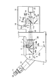
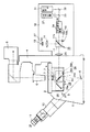
図1は、本発明を倒立型の顕微鏡装置に適用した例の概略構成を示している。図において、1は顕微鏡本体で、この顕微鏡本体1上には、ステージ2が配置されている。このステージ2上には標本3が載置されている。
(First embodiment)
FIG. 1 shows a schematic configuration of an example in which the present invention is applied to an inverted microscope apparatus. In the figure,
顕微鏡本体1には、ステージ2上方に向け照明支柱4が設けられている。この照明支柱4は、先端部をほぼ直角に折り曲げられ、この先端部がステージ2面に対して水平方向に配置されている。
The microscope
照明支柱4の先端部には、透過照明用の光源5が設けられている。この光源5には、ハロゲンランプや水銀ランプなどが用いられる。
A
また、照明支柱4の先端部には、コンデンサ6が設けられている。このコンデンサ6は、光源5の照明光路上に配置されており、光源5からの照明光を標本3の位置に集光するようになっている。
In addition, a
ステージ2の下方には、標本3に近接して対物レンズ7が配置されている。対物レンズ7は、倍率の異なる複数本(図面では1本のみを示している。)が図示しないレボルバーに保持され、このレボルバーの回転操作によって、選択的に観察光路a上に位置されるようになっている。
Below the
また、対物レンズ7は、図示しない焦準ハンドルの操作によりレボルバーとともに、観察光路aに沿って上下動され、ステージ2との相対距離を変化させ、標本3のピント合わせを可能にしている
対物レンズ7下方の観察光路a上には、反射ミラー8が配置されている。反射ミラー8は、標本3を透過し対物レンズ7より拡大された光像を斜め上方向(水平に対し45°の角度)に反射させるようにしている。そして、反射ミラー8で反射された光像は、リレー光学系9でリレーされ、観察鏡筒10に取り付けられた観察手段としての接眼レンズ11に入射し、観察者により目視観察されるようになっている。この場合、接眼レンズ11を取り付けた観察鏡筒10は、顕微鏡本体1の正面に配置されている。
The
顕微鏡本体1の側面、ここでは観察鏡筒10が設けられる顕微鏡本体1正面と反対側になる背面に、投光管12が設けられている。この場合、投光管12は、顕微鏡本体1の背面に水平方向に突出して設けられている。
A
投光管12内には、光源13が設けられている。この光源13は、キセノン又は水銀ランプなどが用いられる。光源13から発せられる照明光の光路上には、コレクタレンズ14および第2の光学素子切換え手段としてのキューブターレット15が配置されている。このキューブターレット15は、複数種類のキューブユニットを保持可能にしたもので、手動または自動により回転切換え可能な構成になっている。図示例では、2種類のキューブユニット16、17が装着され、このうちのキューブユニット16がコレクタレンズ14からの照明光の光路上に位置決めされているものとする。
A
この場合、キューブユニット16には、波長選択光学素子としてのダイクロイックミラー16aが設けられている。ダイクロイックミラー16aは、一種の干渉フィルタで、短波長を反射し、長波長を透過するような特性を有しており、標本3を励起するための励起光波長を反射し、標本3が発する蛍光波長を透過させるようになっている。また、キューブユニット17には、反射光学素子としての全反射ミラー17aが設けられている。全反射ミラー17aは、光源13からの照明光の全てを反射するようになっている。
In this case, the
また、キューブターレット15には、第1の位置検出手段18として、マグネット18aと磁気センサー18bが設けられている。これらマグネット18aと磁気センサー18bは、キューブユニット17の全反射ミラー17aが光路に挿入されたことを検出するものである。
The
キューブユニット16のダイクロイックミラー16a(コレクタレンズ14からの光路上に位置決めされている)の反射光路には、回転ディスク19および結像レンズ20が配置されている。回転ディスク19は、コレクタレンズ14で集光された励起光の集光位置で、標本3と共役の位置でもある点I上に配置され、回転軸19aを中心に回転可能になっている。また、回転ディスク19は、複数のピンホールあるいはスリットのような透孔(図示せず)が形成され、これら透孔を通過した励起光が結像レンズ20に入射するようになっている。さらに、回転ディスク19は、光路に対し挿脱自在になっている。図示例では、回転ディスク19が光路から退避した状態になっている。結像レンズ20は、像側テレセントリックになっていて、通過した光が平行光になるようにしている。
A
キューブユニット16のダイクロイックミラー16a(コレクタレンズ14からの光路上に位置決めされている)の透過光路には、撮像光学系を構成する結像レンズ21が配置されている。この結像レンズ21の結像位置には、撮像手段としてのCCDカメラ22が配置されている。CCDカメラ22には、結像レンズ21を透過した標本3からの蛍光が導かれ撮像面22aに結像される。
An
結像レンズ20からの光路上には、顕微鏡本体1内部の観察光路aと交わる点に、第1の光学素子切換え手段としてのキューブターレット23が配置されている。このキューブターレット23は、複数種類のキューブユニットを保持可能にしたもので、手動または自動により回転切換え可能な構成になっている。図示例では、2種類のキューブユニット24,25が装着され、このうちのキューブユニット24が結像レンズ20からの光路と観察光路aとの交点に位置決めされているものとする。この場合、キューブユニット24には、反射光学素子としての全反射ミラー24aが設けられている。全反射ミラー24aは、結像レンズ20からの光の全てを対物レンズ7側に反射するようになっている。また、キューブユニット25には、波長選択光学素子としてのダイクロイックミラー25aが設けられている。ダイクロイックミラー25aは、短波長を反射し、長波長を透過するような特性を有しており、標本3を励起するための励起光波長を反射し、標本3が発する蛍光波長を透過して、上述した反射ミラー8を介して接眼レンズ11に導くようにしている。
On the optical path from the
キューブターレット23には、第2の位置検出手段26として、マグネット26aと磁気センサー26bが設けられている。これらマグネット26aと磁気センサー26bは、キューブユニット24の全反射ミラー24aが光路に挿入されたことを検出するものである。
The
投光管12内の光源13の前面には、調光手段としてのシャッタ27が設けられている。シャッタ27は、光源13からの照明光の光路に対し、挿脱可能で、必要に応じて照明光を遮光できるようになっている。シャッタ27には、駆動制御部28が接続されている。この駆動制御部28は、第1の位置検出手段18の磁気センサー18bと第2の位置検出手段26の磁気センサー26bが同時に、光路中に挿入される全反射ミラー17aと24aを検出し、それぞれ出力を発生すると、シャッタ27を光路中に挿入して、光源13からの照明光を遮光するようになっている。勿論、駆動制御部28は、磁気センサー18bまたは磁気センサー26bのいずれか一方の検出出力が停止すれば、再びシャッタ27を光路から回避するようになっている。
A
なお、第1および第2の位置検出手段18、26が、光路中に挿入される全反射ミラー17aと24aを同時に検出したときに、警報などを発して手動によりシャッタ27を光路中に挿入するのを促すようにしてもよい。
When the first and
次に、このように構成した実施の形態の作用を説明する。 Next, the operation of the embodiment configured as described above will be described.
まず、CCDカメラ22を用いて蛍光観察像を撮像する場合を説明する。
First, a case where a fluorescence observation image is captured using the
この場合、図1に示すように、キューブターレット15によりキューブユニット16のダイクロイックミラー16aを光路に挿入し、また、キューブターレット23によりキューブユニット24の全反射ミラー24aを光路に挿入する。
In this case, as shown in FIG. 1, the
この状態で、光源13から発生された光は、コレクタレンズ14を介してダイクロイックミラー16aに入射される。ダイクロイックミラー16aでは、標本3の蛍光試薬を励起するための励起光を反射する。ダイクロイックミラー16aで反射した励起光は、結像レンズ20に導光され、平行光となって全反射ミラー24aにより折り返され、対物レンズ7を経て標本3に集光照射される。
In this state, the light generated from the
標本3より蛍光が発せられると、このときの蛍光の波長は、ストークスシフトにより励起光の波長より長波長側にシフトされており、再び対物レンズ7を経て、全反射ミラー24aにより折り返され、結像レンズ20に入射される。そして、図示点Iに標本3と共役な位置を作り、ダイクロイックミラー16aを透過して、結像レンズ21を通ってCCDカメラ22の撮像面22aに結像され、蛍光観察像が撮像される。
When fluorescence is emitted from the
この場合、標本3と共役な点Iに回転ディスク19を挿入し、回転軸19aを中心に回転させるようにすれば、CCDカメラ22による共焦点観察が可能となり、また、回転ディスク19を光路から退避させるようにすれば、CCDカメラ22による通常の蛍光観察ができる。また、キューブユニット16を図示しない他のキューブユニットに交換して特性の異なるダイクロイックミラーを使用すれば、標本3の他の蛍光試薬にも対応することができる。
In this case, if the
次に、接眼レンズ11を用いて蛍光観察像を目視観察する場合を説明する。
Next, the case where the fluorescence observation image is visually observed using the
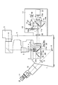
この場合、図2(図1と同一部分には同符号を付している。)に示すように、キューブターレット15によりキューブユニット17の全反射ミラー17aを光路に挿入し、また、キューブターレット23によりキューブユニット25のダイクロイックミラー25aを光路に挿入する。
In this case, the
この状態で、光源13から発生された光は、コレクタレンズ14を介して全反射ミラー17aに入射し、すべて折り返され、結像レンズ20を経てダイクロイックミラー25aに入射される。ダイクロイックミラー25aでは、標本3の蛍光試薬を励起するための励起光を反射する。ダイクロイックミラー25aで反射した励起光は、対物レンズ7を経て標本3に集光照射される。
In this state, the light generated from the
標本3より蛍光が発せられると、このときの蛍光の波長は、ストークスシフトにより励起光の波長より長波長側にシフトされており、対物レンズ7を経て、ダイクロイックミラー25aに入射され、ダイクロイックミラー25aを透過して、反射ミラー8に入射する。そして、反射ミラー8で折り返され、リレー光学系9でリレーされ、観察鏡筒10の接眼レンズ11に入射し、観察者の目視による蛍光観察が可能となる。
When fluorescence is emitted from the
この場合も、キューブユニット25を図示しない他のキューブユニットに交換して特性の異なるダイクロイックミラーを使用すれば、標本3の他の蛍光試薬にも対応することもできる。
In this case, if the
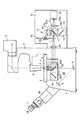
ところで、このような顕微鏡装置では、操作上の誤りにより、図3(図1と同一部分には同符号を付している。)に示すように、キューブターレット15によりキューブユニット17の全反射ミラー17aが光路に挿入された状態で、キューブターレット23によりキューブユニット24の全反射ミラー24aが光路に挿入されることがある。つまり、全反射ミラー17aと全反射ミラー24aが同時に光路上に設定されることがある。この状態では、何らの観察を行なうことができないにも関わらず、光源13からの照明光がコレクタレンズ14を介して全反射ミラー17aに入射し、すべて折り返され、結像レンズ20を経て全反射ミラー24aに入射し、さらに、全反射ミラー24aでもすべて折り返され、対物レンズ7を経て標本3に集光照射される。つまり、この状況下では、光源13からの照明光のすべてが標本3に照射されることとなり、照明光中の短波長の光により標本3の蛍光が急速に退色してしまう虞がある。
By the way, in such a microscope apparatus, due to an operational error, the total reflection mirror of the
これに対し、第1の実施の形態では、キューブターレット15によりキューブユニット17の全反射ミラー17aが光路に挿入されると、第1の位置検出手段18の磁気センサー18bより出力が発生し、また、キューブターレット23によりキューブユニット24の全反射ミラー24aが光路に挿入されると、第2の位置検出手段26の磁気センサー26bより出力が発生する。そして、これら磁気センサー18b、26bが同時に出力を発生したときに、駆動制御部28によりシャッタ27が光路中に挿入されることにより、光源13からの照明光は遮光される。
On the other hand, in the first embodiment, when the
その後、磁気センサー18bまたは磁気センサー26bのいずれか一方の出力が停止すれば、つまり、全反射ミラー17aまたは全反射ミラー24aのいずれか一方が光路から取り除かれれば、駆動制御部28によりシャッタ27は光路から回避される。
Thereafter, if the output of either the
従って、このようにすれば、顕微鏡本体1の側面に設けられた投光管12に、光源13を始めとして、CCDカメラ22、キューブユニット16,17を有するキューブターレット15および回転ディスク19を設けるようにできるので、従来の顕微鏡本体の鏡筒上方に回転ディスクを備えた共焦点装置や撮像装置を重ねて配置したものと比べ、装置全体の重心を低くすることができ、顕微鏡装置を安定して据え付けることができる。
Accordingly, in this manner, the
また、投光管12は、従来のように鏡筒に対する相対的な位置関係の制約を受けることなく、顕微鏡本体1に対して取り付けることができるので、他のアプリケーション装置を増設することも容易で、装置の拡張性を高めることができる。
Further, since the
さらに、投光管12に設けられたキューブターレット15と顕微鏡本体1に設けられたキューブターレット23を切換え、ダイクロイックミラー16aと全反射ミラー24aの組合わせにより、CCDカメラ22による蛍光観察像の撮像を可能とし、また、全反射ミラー17aとダイクロイックミラー25aの組合わせにより、蛍光観察像の目視観察を可能としているが、仮に、操作上の誤りにより、キューブターレット15、23の切換えにより全反射ミラー17a、24aを同時に選択されるような不要な組み合わせが生じると、これら全反射ミラー17a、24aを検出する第1の位置検出手段18および第2の位置検出手段26の出力に応じてシャッタ27が光路に挿入され、光源13からの照明光を遮光するようにしたので、光源13の照明光に含まれる短波長の光により標本3の蛍光が退色してしまうような不都合を確実に回避することができる。
Further, the
なお、上述した実施の形態では、シャッタ27を用いて照明光を遮光したが、回転ディスク19を光路に挿脱させることで光源13からの照明光は遮光させるようにしてもよく、あるいはNDフィルタなどの減光手段でも代用ができる。また、キューブターレット15、23が電動駆動方式のものである場合は、片方が全反射ミラーに設定されているときに、もう片方を全反射ミラーに設定する操作をした場合は、(a)動作を行わない。(b)先に光路に入っている全反射ミラーを光路から退避させてから、後の全反射ミラーを光路に挿入するような動作を行なう。(c)光路にシャッタ27を挿入してから後の全反射ミラーを光路に挿入する。のような制御をおこなうことで照明光を効果的に遮光することができ、標本3の不要な退色を回避できる。
In the above-described embodiment, the illumination light is shielded by using the
(変形例)
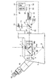
次に、第1の実施の形態の変形例を図4により説明する。なお、図4は、図1と同一部分には、同符号を付している。
(Modification)
Next, a modification of the first embodiment will be described with reference to FIG. In FIG. 4, the same parts as those in FIG.
この場合、キューブターレット15に装着されるキューブユニット17は、全反射ミラー17aの他に、シャッタ27に代わるものとして紫外線カットフィルタ17bを備えている。紫外線カットフィルタ17bは、光源13の照明光に含まれる蛍光の退色に最も影響を及ぼす紫外線域の波長をカットするような特性を有している。
In this case, the
その他は、図1と同様である。 Others are the same as FIG.
このような構成において、蛍光観察像を目視観察するような場合、キューブターレット15によりキューブユニット17の全反射ミラー17aとともに紫紫外線カットフィルタ17bを光路に挿入し、また、キューブターレット23によりキューブユニット25のダイクロイックミラー25aを光路に挿入する。
In such a configuration, when the fluorescence observation image is visually observed, the purple
この状態で、光源13から発せられた光は、コレクタレンズ14を介して紫外線カットフィルタ17bに入射し、照明光に含まれる紫外線域の波長がカットされる。そして、全反射ミラー17aで折り返され、結像レンズ20を経てダイクロイックミラー25aに入射される。ダイクロイックミラー25aでは、標本3の蛍光試薬を励起するための励起光を反射する。ダイクロイックミラー25aで反射した励起光は、対物レンズ7を経て標本3に集光照射される。また、標本3から発せられた蛍光は、ダイクロイックミラー25aを透過し、反射ミラー8で折り返され、リレー光学系9を介して観察鏡筒10の接眼レンズ11に入射し、観察者の目視による蛍光観察が可能となる。
In this state, the light emitted from the
この場合も、誤ってキューブターレット23によりキューブユニット24の全反射ミラー24aが光路に挿入されることがあっても、紫外線カットフィルタ17bが光路中に挿入され、蛍光の退色に最も影響を及ぼす紫外線域の波長をカットするようにしているので、標本3の蛍光の退色を軽減することができる。また、シャッタ27を省略できるので、第1の位置検出手段18、第2の位置検出手段26なども不要にできることを合わせ考えると、構成を大幅に簡単にできる。
Even in this case, even if the
一方、目視観察により紫外線励起の観察を行う場合は、紫外線カットフィルタ17bを光路中に挿入しておくと、光源13より図示しないフィルタ(紫外線域の波長を選択するフィルタ)などを介して入射される励起用の紫外線がカットされてしまう。従って、この場合は、図5(図4と同一部分には同符号を付している。)に示すように、キューブターレット15によりキューブユニット16のダイクロイックミラー16aを光路に挿入する。このダイクロイックミラー16aには、紫外線を反射し、それより長波長の光を透過するような紫外線励起用のものを使用する。同様に、キューブユニット25のダイクロイックミラー25aも紫外線励起用のものを使用する必要がある。このようにすれば、紫外線による励起が可能で、目視観察も可能になる。
On the other hand, when observing ultraviolet excitation by visual observation, if the
(第2の実施の形態)
次に、本発明の第2の実施の形態を説明する。
(Second embodiment)
Next, a second embodiment of the present invention will be described.
図6は、本発明をレーザ走査型共焦点顕微鏡に適用した例の概略構成を示すもので、図1と同一部分には、同符号を付している。 FIG. 6 shows a schematic configuration of an example in which the present invention is applied to a laser scanning confocal microscope, and the same parts as those in FIG. 1 are denoted by the same reference numerals.
この場合、投光管12は、レーザ光源31が設けられている。レーザ光源31から発せられるレーザ光の光路上には、ミラー32が配置されている。また、ミラー32の反射光路には、ダイクロイックミラー33が配置されている。ダイクロイックミラー33は、レーザ光の波長を透過し、標本3から発する蛍光の波長領域を反射するような特性を有している。
In this case, the
ダイクロイックミラー33の透過光路上には、光走査手段としての2次元走査機構34が配置されている。2次元走査機構34は、図示しない2組のガルバノスキャナミラーを有し、これらのガルバノスキャナミラーによりレーザ光を2次元方向に走査するようになっている。
On the transmitted light path of the
2次元走査機構34より出射されるレーザ光の光路上には、光源13からの照明光の光路と交わる点にキューブターレット15が配置されている。この場合、キューブターレット15は、上述したキューブユニット16,17の他に、空穴を有するキューブユニット35を有している。このキューブユニット35は、2次元走査機構34からのレーザ光を空穴を介して直接結像レンズ20に入射させるためのものである。
On the optical path of the laser light emitted from the two-
一方、ダイクロイックミラー33の反射光路上には、共焦点観察手段を構成する共焦点ピンホール36および光検出器37が配置されている。ここでの光検出器37には、例えばフォトマルチプライアが用いられる。
On the other hand, on the reflected light path of the
その他は、図1と同様である。 Others are the same as FIG.
このような構成において、共焦点観察を行なう場合は、図6に示すようにキューブターレット15によりキューブユニット35の空穴を光路に挿入し、また、キューブターレット23によりキューブユニット24の全反射ミラー24aを光路に挿入する。
In such a configuration, when confocal observation is performed, as shown in FIG. 6, the
この状態で、レーザ光源31から発生されたレーザ光は、ミラー32により折り返され、ダイクロイックミラー33を透過し、2次元走査機構34により2次元に走査され、キューブユニット35の空穴を通過して結像レンズ20に導光され、平行光となって全反射ミラー24aにより折り返され、対物レンズ7を経て標本3に集光照射される。
In this state, the laser light generated from the
また、標本3より発せられる蛍光は、対物レンズ7を経て、全反射ミラー24aにより折り返され、2次元走査機構34を経て直線的な光に戻され、ダイクロイックミラー33で反射され、共焦点ピンホール36を通過した後、光検出器37で検出され、画像化および解析処理が行なわれる。
Further, the fluorescence emitted from the
次に、目視により蛍光観察する場合は、図7(図6と同一部分には同符号を付している。)に示すように、キューブターレット15によりキューブユニット17の全反射ミラー17aを光路に挿入し、また、キューブターレット23によりキューブユニット25のダイクロイックミラー25aを光路に挿入する。
Next, in the case of visually observing fluorescence, as shown in FIG. 7 (the same parts as in FIG. 6 are given the same reference numerals), the
この状態で、光源13から発生された光は、コレクタレンズ14を介して全反射ミラー17aに入射し、すべて折り返され、結像レンズ20を経てダイクロイックミラー25aに入射される。ダイクロイックミラー25aでは、標本3の蛍光試薬を励起するための励起光を反射する。ダイクロイックミラー25aで反射した励起光は、対物レンズ7を経て標本3に集光照射される。
In this state, the light generated from the
標本3より蛍光が発せられると、このときの蛍光の波長は、ストークスシフトにより励起光の波長より長波長側にシフトされており、対物レンズ7を経て、ダイクロイックミラー25aに入射され、このダイクロイックミラー25aを透過して、反射ミラー8に入射する。そして、反射ミラー8で折り返され、リレー光学系9でリレーされ、観察鏡筒10の接眼レンズ11に入射し、観察者の目視による蛍光観察が可能となる。
When fluorescence is emitted from the
ところで、この場合も、操作上の誤りにより、図8(図6と同一部分には同符号を付している。)に示すように、キューブターレット15によりキューブユニット17の全反射ミラー17aが光路に挿入された状態で、キューブターレット23によりキューブユニット24の全反射ミラー24aが光路に挿入されることがある。つまり、全反射ミラー17aと全反射ミラー24aが同時に光路上に設定されることがあ。この状態では、何らの観察を行なうことができないにも関わらず、光源13からの照明光がコレクタレンズ14を介して全反射ミラー17aに入射し、すべて折り返され、結像レンズ20を経て全反射ミラー24aに入射し、さらに、全反射ミラー24aでもすべて折り返され、対物レンズ7を経て標本3に集光照射される。つまり、この状況下では、光源13からの照明光のすべてが標本3に照射されることとなり、照明光中の短波長の光により標本3の蛍光が退色してしまう虞がある。
In this case as well, due to an operational error, the
これに対し、第2の実施の形態でも、キューブターレット15によりキューブユニット17の全反射ミラー17aが光路に挿入されると、第1の位置検出手段18の磁気センサー18bより出力が発生し、また、キューブターレット23によりキューブユニット24の全反射ミラー24aが光路に挿入されると、第2の位置検出手段26の磁気センサー26bより出力が発生する。そして、これら磁気センサー18b、26bが同時に出力を発生したときに、駆動制御部28によりシャッタ27を光路中に挿入することにより、光源13からの照明光は遮光される。
On the other hand, also in the second embodiment, when the
その後、磁気センサー18bまたは磁気センサー26bのいずれか一方の出力が停止すれば、つまり、全反射ミラー17aまたは全反射ミラー24aのいずれか一方が光路から取り除かれれば、駆動制御部28によりシャッタ27は、光路から回避される。
Thereafter, if the output of either the
従って、このようにしても第1の実施の形態と同様な効果を得ることができる。 Therefore, even in this way, the same effect as in the first embodiment can be obtained.
また、投光管12に設けられたキューブターレット15と顕微鏡本体1に設けられたキューブターレット23を切換え、空穴を有するキューブユニット35と全反射ミラー24aの組合わせにより、共焦点観察を可能とし、また、全反射ミラー17aとダイクロイックミラー25aの組合わせにより蛍光観察像の目視観察を可能としているが、この場合も、操作上の誤りにより、キューブターレット15、23の切換えにより全反射ミラー17a、24aを同時に選択されるような不要な組み合わせが生じると、第1の位置検出手段18および第2の位置検出手段26の出力に応じてシャッタ27により光源13からの照明光を遮光できるので、光源13の照明光に含まれる短波長の光により標本3の蛍光が退色してしまうような不都合を確実に回避することができる。
In addition, the
なお、本発明は、上記実施の形態に限定されるものでなく、実施段階では、その要旨を変更しない範囲で種々変形することが可能である。例えば、上述した実施の形態では、倒立型の顕微鏡装置について述べたが、正立型の顕微鏡装置にも同様に適用できる。 In addition, this invention is not limited to the said embodiment, In the implementation stage, it can change variously in the range which does not change the summary. For example, in the above-described embodiments, the inverted microscope apparatus has been described, but the present invention can be similarly applied to an upright microscope apparatus.
さらに、上記実施の形態には、種々の段階の発明が含まれており、開示されている複数の構成要件における適宜な組み合わせにより種々の発明が抽出できる。例えば、実施の形態に示されている全構成要件から幾つかの構成要件が削除されても、発明が解決しようとする課題の欄で述べた課題を解決でき、発明の効果の欄で述べられている効果が得られる場合には、この構成要件が削除された構成が発明として抽出できる。 Furthermore, the above embodiments include inventions at various stages, and various inventions can be extracted by appropriately combining a plurality of disclosed constituent elements. For example, even if some constituent requirements are deleted from all the constituent requirements shown in the embodiment, the problem described in the column of the problem to be solved by the invention can be solved, and is described in the column of the effect of the invention. If the above effect is obtained, a configuration from which this configuration requirement is deleted can be extracted as an invention.
1…顕微鏡本体、2…ステージ、3…標本、4…照明支柱
5…光源、6…コンデンサ、7…対物レンズ、8…反射ミラー
9…リレー光学系、10…観察鏡筒、11…接眼レンズ
12…投光管、13…光源、14…コレクタレンズ
15…キューブターレット、16.17…キューブユニット
16a…ダイクロイックミラー、17a…全反射ミラー
17b…紫外線カットフィルタ、18…第1の位置検出手段
18a…マグネット、18b…磁気センサー
19…回転ディスク、19a…回転軸
20…結像レンズ、21…結像レンズ、22…CCDカメラ
22a…撮像面、23…キューブターレット
24.25…キューブユニット、24a…全反射ミラー
25a…ダイクロイックミラー、26…第2の位置検出手段
26a…マグネット、26b…磁気センサー
27…シャッタ、28…駆動制御部、31…レーザ光源
32…ミラー、33…ダイクロイックミラー
34…2次元走査機構、35…キューブユニット
36…共焦点ピンホール、37…光検出器
DESCRIPTION OF
Claims (10)
前記顕微鏡本体側面に設けられ、光源と、少なくとも1個の撮像手段を有する投光管と、
前記光源からの光を前記標本に反射し前記標本からの光を前記観察手段に透過する波長選択光学素子と前記光源からの光を前記標本に全反射する反射光学素子を選択的に光路に挿入する第1の光学素子切換え手段と、
前記投光管内にあって、前記光源からの光を前記第1の光学素子切換え手段に反射し前記標本からの光を前記撮像手段に透過する波長選択光学素子と前記光源からの光を前記第1の光学素子切換え手段に全反射する反射光学素子を選択的に光路に挿入する第2の光学素子切換え手段と、
前記光源からの光を遮光または減光する調光手段と、を具備し、
前記第1および第2の光学素子切換え手段の前記反射光学素子が同時に光路に挿入されたとき、前記調光手段により前記光源の光を遮光または減光させることを特徴とする顕微鏡装置。 A microscope main body having an objective lens arranged close to the specimen, and an observation means for observing the optical image of the specimen through the objective lens;
A light source provided on the side surface of the microscope main body, and a light projecting tube having at least one imaging means;
A wavelength selection optical element that reflects light from the light source to the specimen and transmits light from the specimen to the observation means and a reflection optical element that totally reflects light from the light source to the specimen are selectively inserted into the optical path. First optical element switching means for
A wavelength selection optical element that is in the light projecting tube and reflects light from the light source to the first optical element switching means and transmits light from the sample to the imaging means, and light from the light source to the first light source. Second optical element switching means for selectively inserting a reflective optical element for total reflection into the optical path of one optical element;
A light control means for shielding or dimming light from the light source,
A microscope apparatus characterized in that, when the reflective optical elements of the first and second optical element switching means are simultaneously inserted into an optical path, the light of the light source is blocked or dimmed by the dimming means.
これら第1および第2の位置検出手段が同時に光路に挿入される前記反射光学素子を検出すると、前記調光手段により前記光源の光を遮光または減光させることを特徴とする請求項1乃至3のいずれかに記載の顕微鏡装置。 The first and second optical element switching means include first and second position detection means for detecting that the respective reflective optical elements are inserted in the optical path,
4. When the first and second position detecting means detect the reflective optical element inserted into the optical path at the same time, the light control means blocks or reduces the light of the light source. The microscope apparatus according to any one of the above.
前記顕微鏡本体側面に設けられ、光源と、少なくとも1個の撮像手段を有する投光管と、A light source provided on the side surface of the microscope main body, and a light projecting tube having at least one imaging means;
前記光源からの光を前記標本に反射し前記標本からの光を前記観察手段に透過する波長選択光学素子と前記光源からの光を前記標本に全反射する反射光学素子を選択的に光路に挿入する第1の光学素子切換え手段と、A wavelength selection optical element that reflects light from the light source to the specimen and transmits light from the specimen to the observation means and a reflection optical element that totally reflects light from the light source to the specimen are selectively inserted into the optical path. First optical element switching means for
前記投光管内にあって、前記光源からの光を前記第1の光学素子切換え手段に反射し前記標本からの光を前記撮像手段に透過する波長選択光学素子と前記光源からの光を前記第1の光学素子切換え手段に全反射する反射光学素子を選択的に光路に挿入する第2の光学素子切換え手段と、A wavelength selection optical element that is in the light projecting tube and reflects light from the light source to the first optical element switching means and transmits light from the sample to the imaging means, and light from the light source to the first light source. Second optical element switching means for selectively inserting a reflective optical element for total reflection into the optical path of one optical element;
前記光源からの光を遮光または減光する調光手段と、を具備し、A light control means for shielding or dimming light from the light source,
前記第1および第2の光学素子切換え手段は、それぞれの前記反射光学素子が光路に挿入されたことを検出する第1および第2の位置検出手段を有し、これら第1および第2の位置検出手段が同時に光路に前記反射光学素子が挿入されたことを検出したときに警報を発することを特徴とする顕微鏡装置。The first and second optical element switching means have first and second position detecting means for detecting that the respective reflective optical elements are inserted in the optical path, and these first and second positions are detected. A microscope apparatus characterized in that an alarm is issued when the detecting means simultaneously detects that the reflective optical element is inserted in the optical path.
前記顕微鏡本体側面に設けられ、前記観察手段による観察に用いられる第1の光源と、第1の光源とは異なる第2の光源から出力されるレーザ光を前記標本に2次元走査する2次元走査手段及び前記レーザ光により走査された前記標本からの光を取り込む共焦点観察手段とを有する投光管と、Two-dimensional scanning that is provided on the side surface of the microscope main body and that two-dimensionally scans the sample with a first light source used for observation by the observation means and a laser beam output from a second light source different from the first light source And a light projection tube having confocal observation means for capturing light from the specimen scanned by the laser light,
前記第1の光源からの光を前記標本に反射し前記標本からの光を前記観察手段に透過する波長選択光学素子と前記第2の光源からのレーザ光を前記標本に全反射する反射光学素子を選択的に光路に挿入する第1の光学素子切換え手段と、A wavelength selection optical element that reflects light from the first light source to the specimen and transmits light from the specimen to the observation means, and a reflection optical element that totally reflects laser light from the second light source to the specimen. First optical element switching means for selectively inserting into the optical path;
前記投光管内にあって、前記第1の光源からの光と前記第2の光源からのレーザ光の一方を前記第1の光学素子切換え手段に導くように空穴と反射光学素子の一方を選択的に光路に挿入する第2の光学素子切換え手段と、One of the hole and the reflection optical element is in the light projecting tube so as to guide one of the light from the first light source and the laser light from the second light source to the first optical element switching means. Second optical element switching means for selectively inserting into the optical path;
前記光源からの光を遮光または減光する調光手段と、を具備し、A light control means for shielding or dimming light from the light source,
前記第1の光学素子切換え手段における前記反射光学素子と、前記第2の光学素子切換え手段における前記空穴又は反射光学素子であって前記第1の光源からの光を前記第1の光学素子切換え手段に導く状態にするものとが同時に光路に挿入されたとき、前記調光手段により前記第1の光源の光を遮光または減光させることを特徴とする顕微鏡装置。The reflection optical element in the first optical element switching means, and the hole or reflection optical element in the second optical element switching means, wherein light from the first light source is switched to the first optical element switching means. A microscope apparatus characterized in that when the light to be guided to the means is simultaneously inserted in the optical path, the light of the first light source is blocked or dimmed by the light control means.
Priority Applications (1)
| Application Number | Priority Date | Filing Date | Title |
|---|---|---|---|
| JP2003374634A JP4464654B2 (en) | 2003-11-04 | 2003-11-04 | Microscope equipment |
Applications Claiming Priority (1)
| Application Number | Priority Date | Filing Date | Title |
|---|---|---|---|
| JP2003374634A JP4464654B2 (en) | 2003-11-04 | 2003-11-04 | Microscope equipment |
Publications (3)
| Publication Number | Publication Date |
|---|---|
| JP2005140850A JP2005140850A (en) | 2005-06-02 |
| JP2005140850A5 JP2005140850A5 (en) | 2008-02-28 |
| JP4464654B2 true JP4464654B2 (en) | 2010-05-19 |
Family
ID=34686289
Family Applications (1)
| Application Number | Title | Priority Date | Filing Date |
|---|---|---|---|
| JP2003374634A Expired - Fee Related JP4464654B2 (en) | 2003-11-04 | 2003-11-04 | Microscope equipment |
Country Status (1)
| Country | Link |
|---|---|
| JP (1) | JP4464654B2 (en) |
Cited By (1)
| Publication number | Priority date | Publication date | Assignee | Title |
|---|---|---|---|---|
| US20180045942A1 (en) * | 2016-08-09 | 2018-02-15 | Olympus Corporation | Microscope apparatus |
Families Citing this family (2)
| Publication number | Priority date | Publication date | Assignee | Title |
|---|---|---|---|---|
| JP5056871B2 (en) * | 2010-03-02 | 2012-10-24 | 横河電機株式会社 | Confocal microscope system |
| JP6081056B2 (en) * | 2011-12-06 | 2017-02-15 | オリンパス株式会社 | Laser scanning microscope |
-
2003
- 2003-11-04 JP JP2003374634A patent/JP4464654B2/en not_active Expired - Fee Related
Cited By (2)
| Publication number | Priority date | Publication date | Assignee | Title |
|---|---|---|---|---|
| US20180045942A1 (en) * | 2016-08-09 | 2018-02-15 | Olympus Corporation | Microscope apparatus |
| US10133049B2 (en) * | 2016-08-09 | 2018-11-20 | Olympus Corporation | Microscope apparatus automatically changes illumination according to various observation methods |
Also Published As
| Publication number | Publication date |
|---|---|
| JP2005140850A (en) | 2005-06-02 |
Similar Documents
| Publication | Publication Date | Title |
|---|---|---|
| CN101031837B (en) | Method and apparatus for fluorescent confocal microscopy | |
| JP3283499B2 (en) | Laser microscope | |
| JP5897563B2 (en) | System for synchronization in line scanning microscope | |
| US7480046B2 (en) | Scanning microscope with evanescent wave illumination | |
| JP5307353B2 (en) | Multiphoton excitation laser scanning microscope and multiphoton excitation fluorescence image acquisition method | |
| JP2008249965A (en) | Confocal microscopic system | |
| JP2006171024A (en) | Multi-point fluorescence spectrophotometry microscope and multi-point fluorescence spectrophotometry method | |
| JP5311195B2 (en) | Microscope equipment | |
| JP5053691B2 (en) | Specimen scanner device and specimen position detection method using the device | |
| JP2008203813A (en) | Scanning microscope | |
| JP3861357B2 (en) | Microscope revolver and microscope integrated with optical device | |
| WO2016132451A1 (en) | Microscope | |
| JP4725967B2 (en) | Minute height measuring device and displacement meter unit | |
| JP4601266B2 (en) | Laser microscope | |
| US6906312B2 (en) | Scanning microscope having a microscope stand | |
| JP4464654B2 (en) | Microscope equipment | |
| JP2002023059A (en) | Microscope assembly | |
| JP4898588B2 (en) | Scanning microscope | |
| JP2018194634A (en) | Light field microscope | |
| JP3486754B2 (en) | Scanning optical microscope | |
| JP3297647B2 (en) | Confocal scanning microscope | |
| JP4409390B2 (en) | Optical scanning confocal observation device | |
| JP6249783B2 (en) | microscope | |
| JP2002148521A (en) | Microscope | |
| JP2008185432A (en) | Drug discovery screening apparatus |
Legal Events
| Date | Code | Title | Description |
|---|---|---|---|
| A621 | Written request for application examination |
Free format text: JAPANESE INTERMEDIATE CODE: A621 Effective date: 20061101 |
|
| A521 | Written amendment |
Free format text: JAPANESE INTERMEDIATE CODE: A523 Effective date: 20080109 |
|
| TRDD | Decision of grant or rejection written | ||
| A01 | Written decision to grant a patent or to grant a registration (utility model) |
Free format text: JAPANESE INTERMEDIATE CODE: A01 Effective date: 20100126 |
|
| A01 | Written decision to grant a patent or to grant a registration (utility model) |
Free format text: JAPANESE INTERMEDIATE CODE: A01 |
|
| A61 | First payment of annual fees (during grant procedure) |
Free format text: JAPANESE INTERMEDIATE CODE: A61 Effective date: 20100219 |
|
| FPAY | Renewal fee payment (event date is renewal date of database) |
Free format text: PAYMENT UNTIL: 20130226 Year of fee payment: 3 |
|
| R151 | Written notification of patent or utility model registration |
Ref document number: 4464654 Country of ref document: JP Free format text: JAPANESE INTERMEDIATE CODE: R151 |
|
| FPAY | Renewal fee payment (event date is renewal date of database) |
Free format text: PAYMENT UNTIL: 20140226 Year of fee payment: 4 |
|
| S531 | Written request for registration of change of domicile |
Free format text: JAPANESE INTERMEDIATE CODE: R313531 |
|
| R350 | Written notification of registration of transfer |
Free format text: JAPANESE INTERMEDIATE CODE: R350 |
|
| LAPS | Cancellation because of no payment of annual fees |