JP4463983B2 - Optoacoustic imaging device - Google Patents
Optoacoustic imaging device Download PDFInfo
- Publication number
- JP4463983B2 JP4463983B2 JP2000547913A JP2000547913A JP4463983B2 JP 4463983 B2 JP4463983 B2 JP 4463983B2 JP 2000547913 A JP2000547913 A JP 2000547913A JP 2000547913 A JP2000547913 A JP 2000547913A JP 4463983 B2 JP4463983 B2 JP 4463983B2
- Authority
- JP
- Japan
- Prior art keywords
- optical fiber
- bragg grating
- imaging
- wavelength
- present
- Prior art date
- Legal status (The legal status is an assumption and is not a legal conclusion. Google has not performed a legal analysis and makes no representation as to the accuracy of the status listed.)
- Expired - Fee Related
Links
Images


Classifications
-
- A—HUMAN NECESSITIES
- A61—MEDICAL OR VETERINARY SCIENCE; HYGIENE
- A61B—DIAGNOSIS; SURGERY; IDENTIFICATION
- A61B8/00—Diagnosis using ultrasonic, sonic or infrasonic waves
- A61B8/12—Diagnosis using ultrasonic, sonic or infrasonic waves in body cavities or body tracts, e.g. by using catheters
-
- A—HUMAN NECESSITIES
- A61—MEDICAL OR VETERINARY SCIENCE; HYGIENE
- A61B—DIAGNOSIS; SURGERY; IDENTIFICATION
- A61B5/00—Measuring for diagnostic purposes; Identification of persons
- A61B5/0093—Detecting, measuring or recording by applying one single type of energy and measuring its conversion into another type of energy
- A61B5/0095—Detecting, measuring or recording by applying one single type of energy and measuring its conversion into another type of energy by applying light and detecting acoustic waves, i.e. photoacoustic measurements
-
- A—HUMAN NECESSITIES
- A61—MEDICAL OR VETERINARY SCIENCE; HYGIENE
- A61B—DIAGNOSIS; SURGERY; IDENTIFICATION
- A61B5/00—Measuring for diagnostic purposes; Identification of persons
- A61B5/0093—Detecting, measuring or recording by applying one single type of energy and measuring its conversion into another type of energy
- A61B5/0097—Detecting, measuring or recording by applying one single type of energy and measuring its conversion into another type of energy by applying acoustic waves and detecting light, i.e. acoustooptic measurements
-
- A—HUMAN NECESSITIES
- A61—MEDICAL OR VETERINARY SCIENCE; HYGIENE
- A61B—DIAGNOSIS; SURGERY; IDENTIFICATION
- A61B8/00—Diagnosis using ultrasonic, sonic or infrasonic waves
- A61B8/56—Details of data transmission or power supply
-
- G—PHYSICS
- G01—MEASURING; TESTING
- G01H—MEASUREMENT OF MECHANICAL VIBRATIONS OR ULTRASONIC, SONIC OR INFRASONIC WAVES
- G01H9/00—Measuring mechanical vibrations or ultrasonic, sonic or infrasonic waves by using radiation-sensitive means, e.g. optical means
- G01H9/004—Measuring mechanical vibrations or ultrasonic, sonic or infrasonic waves by using radiation-sensitive means, e.g. optical means using fibre optic sensors
-
- A—HUMAN NECESSITIES
- A61—MEDICAL OR VETERINARY SCIENCE; HYGIENE
- A61B—DIAGNOSIS; SURGERY; IDENTIFICATION
- A61B17/00—Surgical instruments, devices or methods, e.g. tourniquets
- A61B17/22—Implements for squeezing-off ulcers or the like on the inside of inner organs of the body; Implements for scraping-out cavities of body organs, e.g. bones; Calculus removers; Calculus smashing apparatus; Apparatus for removing obstructions in blood vessels, not otherwise provided for
- A61B2017/22038—Implements for squeezing-off ulcers or the like on the inside of inner organs of the body; Implements for scraping-out cavities of body organs, e.g. bones; Calculus removers; Calculus smashing apparatus; Apparatus for removing obstructions in blood vessels, not otherwise provided for with a guide wire
- A61B2017/22042—Details of the tip of the guide wire
-
- A—HUMAN NECESSITIES
- A61—MEDICAL OR VETERINARY SCIENCE; HYGIENE
- A61B—DIAGNOSIS; SURGERY; IDENTIFICATION
- A61B90/00—Instruments, implements or accessories specially adapted for surgery or diagnosis and not covered by any of the groups A61B1/00 - A61B50/00, e.g. for luxation treatment or for protecting wound edges
- A61B90/36—Image-producing devices or illumination devices not otherwise provided for
- A61B90/361—Image-producing devices, e.g. surgical cameras
- A61B2090/3614—Image-producing devices, e.g. surgical cameras using optical fibre
Landscapes
- Health & Medical Sciences (AREA)
- Life Sciences & Earth Sciences (AREA)
- Physics & Mathematics (AREA)
- Engineering & Computer Science (AREA)
- Surgery (AREA)
- Pathology (AREA)
- Biophysics (AREA)
- Biomedical Technology (AREA)
- Heart & Thoracic Surgery (AREA)
- Medical Informatics (AREA)
- Molecular Biology (AREA)
- Veterinary Medicine (AREA)
- Animal Behavior & Ethology (AREA)
- General Health & Medical Sciences (AREA)
- Public Health (AREA)
- Acoustics & Sound (AREA)
- Radiology & Medical Imaging (AREA)
- Nuclear Medicine, Radiotherapy & Molecular Imaging (AREA)
- General Physics & Mathematics (AREA)
- Computer Networks & Wireless Communication (AREA)
- Ultra Sonic Daignosis Equipment (AREA)
- Investigating Or Analyzing Materials By The Use Of Ultrasonic Waves (AREA)
- Measurement Of Mechanical Vibrations Or Ultrasonic Waves (AREA)
- Measurement Of The Respiration, Hearing Ability, Form, And Blood Characteristics Of Living Organisms (AREA)
- Transducers For Ultrasonic Waves (AREA)
Abstract
Description
【0001】
【関連出願】
本願は、1998年3月5日に出願された米国仮出願第60/076,862号を優先権として主張するものである。
【0002】
【技術分野】
本願発明は、血管内のガイドワイヤとして用いられ得る、血管又は非血管の画像化用の全方向型の画像化装置に関する。
【0003】
【背景技術】
血管内および非血管内の画像化は、対象となる血管壁の構造、血小板解析、および疾病プロセスについての情報の如く、血管造影による画像化手法では入手できない情報を提供するために非常に重要な技術である。それはまた、血管導入(vascular intervention)、特に、ステント展開(stent deployment)の補助としても非常に重要である。
【0004】
従来技術である血管内超音波診断(IVUS)装置は、一般的にカテーテルを介して用いられることに適するとされ、本来は機械式又は半導体式の装置である。機械式のIVUSカテーテルでは、画像の走査は、小型の音響トランスミッタを機械的に回転させる回転駆動軸により達成される。該駆動軸と前記送信機の殆どとは、柔軟性のあるカテーテルの本体内に位置している。これらの装置の設計では、概して、限られた映像範囲内でのトラッキングに問題を生じ、また、回転中におけるカテーテルの振動は、動脈痙攣の患者にリスクを引き起こすことになる。
【0005】
前記半導体式のIVUSカテーテルは、回転する駆動軸を有さず、前記IVUS内に配された多数の圧電素子から発生される電気的な衝撃で走査することにより画像を生成する。各圧電素子は、コンピュータの如きドライバによって制御される。従来の半導体式のIVUS装置は、一般的に、ガイドワイヤを受容すべくなされたルーメンを有し、機械式のものと比べて前記装置のトラッキング性と押し易さとを向上する同軸ケーブル式の設計を有する。
【0006】
従来の機械式と半導体式のIVUSカテーテルの1つの欠点は、一般的には約1.2 mmであるその外径である。部品サイズおよび雑音の影響による機械的な制約が、より小さな直径をもつ装置の商業的に実現可能な製造をかなり制限してきた。加えて、これらの両装置は従来の血管内カテーテル手法、すなわち、ガイドワイヤに亘って配されたカテーテルとともに用いられなければならない。
【0007】
或る従来技術の超音波カテーテルの特許では、ポールド(poled)フッ化ポリビニルジエン(PVDF)の如き、圧電性のトランスデューサとして機能するように活性領域中に点極性化(spot polarized)され得る、柔軟性のある圧電性のプラスチック材料の薄膜を記述している。該装置において、PVDF膜は、送信機と受信機との両方として用いられる。しかし、小さい(直径1.2 mmより小さい)画像化カテーテルに多重素子とともにこの技術を適合させるのは、いくつかの理由で難しい。1つの理由は、長い電極導体(長さが1 mより長い)のコンデンサと比べて、小さい表面積を持つ各受信要素の非常に低い電気コンデンサである。前記装置におけるこの要素の関係は、概して低い信号/雑音の関係という結果となる。その信号対雑音比は、受信機の近くでプリアンプを用いることにより増大され得るが、1.2 mmより小さい外径の空間内にプリアンプを物理的に収容することは非常に難しい。もう1つの理由としては、前記装置内に、長く、ぎっしりと束ねられた導体によって経験する大きな信号混信である。
【0008】
血管内装置において光ファイバに超音波を結合するその他の関係する従来技術は、圧電材料の薄板上に正確に配置するトランスデューサを含む。該トランスデューサは、板材の束の表面又は内側を伝搬する超音波音響表面波を発生する。しかし、これらの装置は、画像ではなくドップラー信号を発生するという点で制限されており、それらの探索範囲は、カテーテルの通路の丁度前の領域だけに限られている。また、圧電性のチップは、1 mmより小さい、より重要なことには0.5 mmより小さい輪郭直径を持つ装置内で用いられるには十分小さいわけではない。
【0009】
市販の圧電性のセラミックおよびPVDF製のIVUS装置の殆どにおいて、1つの重要な問題は、約1 mmより小さい直径を持つ超音波画像化カテーテルを構成する難しさであり、信号対雑音比は、前記装置が容易に用いられるように十分に高くなる。そのような装置もまた、従来の構成部品を用いて製造することは機械的見地から難しい。
【0010】
従って、約1 mmより小さい、より好ましくは0.5 mmより小さい直径を持ち、上述のような従来のIVUS装置により高い信号対雑音比を持つ血管内超音波画像化装置を持つことは有用であろう。また、1 mmより小さい装置輪郭を要求するような非血管に対応する画像化装置を持つことも有用であろう。
【0011】
【発明の開示】
本願発明は、光学音響手法を用いた血管又は非血管画像化のためのガイドワイヤ式の画像化装置であり、1 mmより小さい、最も好ましくは0.5 mmより小さい輪郭直径を持つ装置である。本願発明の画像化装置は、少なくとも1つ以上のブラッグ・グレーティングと、圧電性の、又は圧電性セラミックを被覆された単一モードの光ファイバを有し、該装置は全方向(360°)画像化を達成することができる。本願発明における画像化ガイドワイヤは、血管に導入するためのガイドワイヤとして機能することができ、またバルーン膨張(balloon inflation)およびステント展開時にリアルタイムな画像化を可能にする。従って、カテーテルを基にした画像化システムを用いた場合には得られない臨床的情報を提供する。本願発明装置は、蛍光透視時間を含む全体の処理時間を短縮することを可能にし、また、患者と操作者が放射線に晒されることも少なくするであろう。
【0012】
従って、本願発明の1つの態様は、1 mmより小さい、最も好ましくは0.5 mmより小さい輪郭を持つ血管又は非血管画像化用の光学音響装置を備える。
【0013】
本願発明の別の態様では、カテーテル挿入前の血管導入手順の間と処置の間中とにおけるリアルタイム画像を生成するガイドワイヤ式の画像化装置を備える。
【0014】
本願発明の更なる態様では、全方向360度の画像化の能力を有する装置を備える。
【0015】
本願発明の更に別の態様では、従来の血管内画像化装置より改善された信号対雑音比を持つ血管内画像化技法を備える。
【0016】
【好ましい実施の形態の詳細な説明】
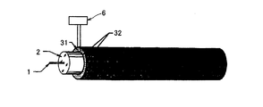
本願発明装置は、例えば単独の光ファイバを用いるが、少なくとも部分的に二酸化ケイ素からなるグラスファイバに限定されるものではない。一般的な光ファイバの基本的な構造は、図2に図解されるように層状のガラス製のシリンダから成る。コア1と呼ばれるシリンダが中央にあり、それを囲むクラッディング2と呼ばれる、できる限り多層加工されたガラス製のシリンダ状殻がある。このシリンダは、或る種、通常合成樹脂(アクリレートの如き)の保護被覆3により囲まれている。環境からの保護のためと被覆単独の強さより機械的に強化するため、ファイバは、通例ケーブルの中に組み込まれる。代表的なケーブルは、鋼鉄やケブラー製の糸のような強化部材5内にファイバを入れるようなポリエチレン製のシース4を持つ。
【0017】
光ファイバは、その屈折率と寸法に基づいて大雑把に分類することができる。
【0018】
図2は圧電被覆により覆われた光ファイバを示し、交流電圧発電機6が何れか一方の被覆面に定められた電極32に取り付けられている。発電機6は、電極32に電気的な衝撃送り、その衝撃がジャケット31内に機械的な振動を引き起こす。
【0019】
最近、ファイバ・ブラッグ・グレーティング(FBG)センサが遠距離通信等ののその広範囲の応用可能性のために非常に注目を集めている。FBGは、光ファイバ構造の一体部分を形成し、製造時あるいは製造後の記入済み内部コアであることができる。
【0020】
図3に示されるように、広帯域光レーザ7により照らされるとき、均一ピッチのFBG素子8は、nはファイバコアの指数でありΛはグレーティング周期を表す、λ=2nΛにより与えらるブラッグ波長λに関して集まった狭帯域要素を反射する。調整可能なレーザ7と該ファイバ上の異なる場所に位置する異なるグレーティング周期(各周期は約0.5μ)を用いて、各グレーティング位置を個別に計測することが可能である。
【0021】
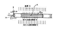
(実施例1)
本願発明の1つの実施例が図4に示されている。この実施例は、ブラッグ・グレーティング8を伴う単一モードの光ファイバと、圧電性の又は圧電性セラミックのジャケット31とを有する。該被覆は、いかなる圧電性の又は圧電性セラミックの材料でもよく、1つの好ましい材料はポールドPVDFである。その他の被覆材料も、適当な柔軟性と圧電性とを持つ限り本願発明に使えると思われる。
【0022】
図4に示されるような本願発明における装置の1つの好ましい実施例において、発電機6が超音波衝撃10をブラッグ・グレーティング8と、装置が位置するところの外部媒質、例えば血液13との両方へ発信する。一次衝撃と反射衝撃11とは、ブラッグ・グレーティング8により受信され、光検出器やオシロスコープのような従来の手法を用いて電子機器9に記録される。記録信号から、従来技法で相応する画像が生成される。ゆえに本願発明は、全方向ソナー(パルス受信機)を各画像化位置で用いる。もし機械的な変形が光ファイバ内で現れた場合、それは反射光の変調を引き起こし電子機器9により記録される。
【0023】
本願発明に基づいて構成された様々な装置において、被覆の厚さと光ファイバの直径は大きく変えることができ、唯一の要件は装置全体が1 mmより小さい、最も好ましくは300μより小さいであることであり、該装置より発生する信号が画像を生成するのに適していることである。
【0024】
本願発明の超音波送信装置は、好ましくは1 mmより小さい、最も好ましくは300μより小さい総輪郭直径を持つ圧電能動(ポールド)PVDF被覆により覆われた単一ファイバを有する。また本願発明の原理に従い、装置を約200μ又はそれより小さい輪郭で製作することもできることが予期されている。その他の周波数送信機を伴う装置もまた、応用が常識でわかるように本願発明の原理に従い構成することができる。本願発明装置は、送信機の任意の所望の周波数を有する。
【0025】
(実施例2)
減衰珪素製のファイバを用いて信号の周波数帯域を拡張することも可能である。本願発明の好ましい実施例のこの態様においては、周波数帯域の拡張は、時間内の信号の短縮を引き起こし、受信信号の解像度を改善する。例えば、本願発明装置において減衰ファイバを用い、実験条件により別の結果となることもあるが、約110の信号の周波数帯域の全幅を達成した。もし減衰ファイバが用いるなら40 MHzより小さいを送信する送信機を用いることができる。
【0026】
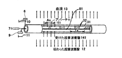
(実施例3)
図5に示す如く、本願発明に係る画像化装置のいま1つの他の好ましい実施例は、異なる周期を有し、各周期は約0.5μである複数のブラッグ・グレーティング81を備える。多ブラッグ・グレーティングを用いることによって、分配された1セットのソナーが得られる。前述した如く調整可能なレーザ71を利用することによって、全方向アレイに亘るスキャンを得る。光学波長の数百倍であるブラッグ・グレーティングの長さLBは、光学ビームの相当の部分を反射するのに十分である。前記超音波衝撃141は、アパーチャAxと等しい周期Aiを有する前記ブラッグ・グレーティング81によってのみ受容される。
【0027】
(実施例4)
図6に示す如き本願発明装置の更に別の好ましい実施例においては、複数のブラッグ・グレーティングに代えて、前記装置は、可変周期を有する単一の可変グレーティングを伴っている。可変レーザが波長l1に調整される場合、前記受容要素は前記ブラッグ・グレーティングである。前記レーザ波長がその他の波長λ2〜6に調整される場合、前記ファイバの軸に沿った前記ブラッグ・グレーティングの対応する位置付けもまた調整される。
【0028】
40 MHzの周波数のトランスミッタと、アパーチャAx=151〜200μとを有する装置にあっては、本願発明により得られるレセプションは、満足のいく画像化を提供することが判った。
【0029】
(実施例5)
図7に示す如き本願発明装置の更に別の好ましい実施例においては、強化部材は付加的に加えることが可能である。この強化部材は、非常に薄く、そして、この強化部材を有していても本願発明装置は、直径が1 mmよりも小さくなることが予想される。
【0030】
本願発明の全方向スキャン能力を維持するために、前記光ファイバは、複数の矩形アパーチャ15を備える強化部材51内に配される。これらのアパーチャ15は、軸x=Axに沿った長さ寸法151と、周方向長さ
【0031】
【数1】
![]()
とを有する。好ましい実施例において、前記アパーチャは、矩形であるが、その他の形状を用いることも可能である。前記アパーチャ15は、前記装置の画像化部分に亘って分配され得、図9に示す如く、例えば螺旋状の形態に分配され得る。
【0033】
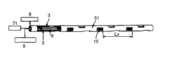
(実施例6)
図8に示す如く、実施例6は、本願発明装置のカテーテル形態であって、前記軸および前記周面の両方に沿った超音波走査を実現する。これは、複数のブラッグ・グレーティング8を有する単一モードの光ファイバ2からなる。該光ファイバには、ジャケット3と、強化部材51とが設けられ、アパーチャ15の群を有している。前記強化部材は、金属の如く、任意の硬く、柔軟で、耐久性のある生物学的適合性材料から製作され得る。アパーチャは、強化部材の表面上に均一に配され、両方が長さおよび角度に沿っている。この装置の外径は、1 mmよりも小さく、最も好ましくは0.5 mmよりも小さい。本装置は、最も好ましい400μよりも小さい外径を更に有する可能性があると予想される。前記アパーチャは、従来の光化学技術を用いて製造され得る。
【0034】
図8に示す如く、前記装置は、
【0035】
【数2】
![]()
のアパーチャのアレイを有するように示してある。発電機6からPVDFジャケット3の電極へ電気的衝撃を与えることによって、全てのアパーチャに対して同時に音響的な衝撃を発生する。超音波衝撃は、前記光ファイバの表面に対して直交する方向に延び、非均一媒質(組織)から反射されて戻ってくる。前記レーザ71を回転することによって、受けた超音波信号の走査を実現することが可能である。電子機器9は、結果としての画像を受け、処理し、そして、表示する。走査の走査周期Lsは長手方向に0.5〜1.0 mm、前記ファイバの周りの方向数は5〜10と推測できる。
【0037】
(実施例7)
本願発明の設計では、1つよりも多くの光ファイバを備えることも可能である。前記強化部材内に複数のファイバがある場合には、前記周期を低減し、前記走査の方向数を増大することが可能である。
【0038】
(実施例8)
図9は、強化部材52の変化態様を示し、螺旋状の強化部材を備えている。この部材の使用は、円滑な走査を実現し、アパーチャを有する強化部材よりも製造が容易であると思われる。
【0039】
(実施例9)
図10に示す如く、本願発明装置の別の態様は、前記ファイバに沿った周期Lを有する可変直径のクラッディングであって、好ましくは、珪素製である。この態様は、ビーズ21の使用によって実現され、音響波に対する増大した感度に起因する。最大効率は、前記周期Lcが次の共振長さの1つと等しい場合に実現される:水Lc1、
【0040】
【数3】
![]()
、における音響波長と略等しい;又は珪素ファイバLc2における見かけ上のラム波長に等しい。
【0042】
この実施例において、前記ブラッグ・グレーティングは、光波と相互に作用し合い、前記ビーズによって形成された音響グレーティングと相互に作用し合う。
【0043】
(実施例10)
図10に示す如く、感度fにおける随意的な増大は、充填剤16が前記ビーズの間の間隙を充填するのに用いられる場合に、前記装置によって随意的に受けられ得る。この充填剤は、固体ポリマー、ゲル、液体、又はその他の適宜の材料の如き、比較的小さい音響インピーダンスを有する材料から製作される。感度の更に付加的な増大の目的としては、間隙を充填する充填剤は、水(血液)中での音速よりも低い音速cfである、つまり、cf<1500 m/secの材料から選択される。このような材料の一例は、音速cf〜1000 m/secを有するシリコンゴムである。前記音速差の結果として、エネルギ収束が達成される。従って、前記充填剤は、信号収集レンズとして作用する。
【0044】
(実施例11)
本願発明装置の更に別の態様は、図11に示す如く、螺旋状のジャケット22を備えている。
【0045】
(実施例12)
別の実施例(図12に示す)は、前記ジャケットに付加的なリブ23を備えている。リブを有する装置の一例において、40 MHzの共振を達成すべく、珪素製のリブは、高さHr=10ミクロンおよび厚さTr=4.5ミクロンの概略寸法を有するべきである。リブ23の振動は、前記ファイバ軸での付加的な変形を促し、従って、感度の増大に起因する。従来から知られているマイクロマシン技術によってリブを製作することが可能である。
【0046】
リブの実施例の変形において、前記リブは、変化する厚さを有することが可能であって、これは、音響的減衰、従って、帯域幅および解像度の増大に導くと考えられる。リブ23のそれぞれが異なる高さHrおよび幅Trを有する場合、これらは、異なる周波数で共振する。
【0047】
(実施例13)
感度における更に付加的な増大の目的にあっては、前記強化部材のアパーチャは、速度cL>1500 m/sec、図13に示す如く、収束レンズを形成する外面曲率を有する材料で充填され得る。
【0048】
しかして、前記好ましい実施例の上述した説明から理解されるように本願発明の目的は達成される。本実施例の態様は、本願発明の目的から逸脱しない限り当業者にとっては明白である。上述した説明および添付の図面に含まれた全ての内容は、本願発明を具現化するためのものであって、本願発明の目的を限定するものではない。
【図面の簡単な説明】
【図1】 従来の光ファイバの模式図である。
【図2】 PVDFで被覆された光ファイバの模式図である。
【図3】 ファイバ・ブラッグ・グレーティング式のセンサの模式図である。
【図4】 PVDFおよびFBG式の本願発明の超音波パルス受信機の模式図である。
【図5】 PVDFおよびFBG式の複数のブラッグ・グレーティングを有する超音波パルス受信機の模式図である。
【図6】 PVDFおよびFBG式の複数の可変ブラッグ・グレーティングを有する超音波パルス受信機の模式図である。
【図7】 強化部材を備えた本願発明の光ファイバの模式図である。
【図8】 本願発明の超音波画像化カテーテルの模式図である。
【図9】 螺旋状の強化部材を備えた本願発明のカテーテルの模式図である。
【図10】 ビーズ形にクラッディングされたファイバの模式図である。
【図11】 ビーズ・クラッディングと螺旋状の強化部材とを備えた本願発明のファイバの模式図である。
【図12】 ビーズ・クラッディングとリブとを備えた本願発明装置の模式図である。
【図13】 レンズ・アパーチャを付した本願発明のカテーテルの模式図である。
【符号の説明】
1……コア
2……クラッディング
13……血液
31……圧電性又は非圧電性のジャケット
32……電極
8,81,82……ブラッグ・グレーティング[0001]
[Related Applications]
This application claims US provisional application No. 60 / 076,862, filed Mar. 5, 1998, as a priority.
[0002]
【Technical field】
The present invention relates to an omnidirectional imaging device for imaging blood vessels or non-blood vessels that can be used as a guide wire in blood vessels.
[0003]
[Background]
Intravascular and non-vascular imaging is very important to provide information that is not available with angiographic imaging techniques, such as information about the structure of the target vessel wall, platelet analysis, and disease processes. Technology. It is also very important as an aid in vascular intervention, especially stent deployment.
[0004]
Prior art intravascular ultrasound (IVUS) devices are generally considered suitable for use via a catheter and are essentially mechanical or semiconductor devices. In a mechanical IVUS catheter, image scanning is accomplished by a rotating drive shaft that mechanically rotates a small acoustic transmitter. The drive shaft and most of the transmitter are located within the body of the flexible catheter. The design of these devices generally creates problems with tracking within a limited image range, and the vibration of the catheter during rotation can pose a risk to patients with arterial spasm.
[0005]
The semiconductor IVUS catheter does not have a rotating drive shaft, and generates an image by scanning with an electric shock generated from a large number of piezoelectric elements arranged in the IVUS. Each piezoelectric element is controlled by a driver such as a computer. Conventional semiconductor IVUS devices generally have a lumen designed to receive a guide wire and have a coaxial cable design that improves the tracking and pushability of the device compared to mechanical ones. Have
[0006]
One drawback of conventional mechanical and semiconductor IVUS catheters is their outer diameter, which is typically about 1.2 mm. Mechanical constraints due to component size and noise effects have significantly limited the commercially feasible manufacturing of devices with smaller diameters. In addition, both of these devices must be used with a conventional intravascular catheter approach, i.e., a catheter placed over a guidewire.
[0007]
Some prior art ultrasound catheter patents are flexible, such as poled fluorinated polyvinyldiene (PVDF), which can be spot polarized in the active region to function as a piezoelectric transducer. Describes a thin film of piezoelectric plastic material. In the device, PVDF membrane is used as both transmitter and receiver. However, adapting this technique with multiple elements to a small (less than 1.2 mm diameter) imaging catheter is difficult for several reasons. One reason is the very low electrical capacitance of each receiving element with a small surface area compared to capacitors with long electrode conductors (lengths greater than 1 m). This elemental relationship in the device generally results in a low signal / noise relationship. Its signal-to-noise ratio can be increased by using a preamplifier near the receiver, but it is very difficult to physically accommodate the preamplifier in an outer diameter space of less than 1.2 mm. Another reason is the large signal interference experienced by long, tightly bundled conductors within the device.
[0008]
Other related prior art for coupling ultrasound to an optical fiber in an intravascular device includes a transducer that is precisely placed on a thin plate of piezoelectric material. The transducer generates an ultrasonic acoustic surface wave propagating on the surface or inside of a bundle of plate materials. However, these devices are limited in that they generate a Doppler signal rather than an image, and their search range is limited to the area just before the catheter passage. Also, a piezoelectric tip is not small enough to be used in a device with a contour diameter of less than 1 mm, more importantly less than 0.5 mm.
[0009]
In most commercially available piezoelectric ceramic and PVDF IVUS devices, one important issue is the difficulty of constructing an ultrasound imaging catheter with a diameter of less than about 1 mm, and the signal to noise ratio is: High enough that the device is easy to use. Such devices are also difficult from a mechanical standpoint to manufacture using conventional components.
[0010]
Therefore, it would be useful to have an intravascular ultrasound imaging device that has a diameter less than about 1 mm, more preferably less than 0.5 mm, and has a higher signal-to-noise ratio than conventional IVUS devices as described above. . It would also be useful to have an imaging device for non-blood vessels that requires a device profile of less than 1 mm.
[0011]
DISCLOSURE OF THE INVENTION
The present invention is a guidewire imaging device for vascular or non-vascular imaging using optoacoustic techniques, and is a device having a contour diameter of less than 1 mm, most preferably less than 0.5 mm. The imaging device of the present invention comprises at least one Bragg grating and a single mode optical fiber coated with piezoelectric or piezoelectric ceramic, the device being an omnidirectional (360 °) image. Can be achieved. The imaging guidewire in the present invention can function as a guidewire for introduction into a blood vessel and allows real-time imaging during balloon inflation and stent deployment. Therefore, it provides clinical information that is not available when using catheter-based imaging systems. The device of the present invention makes it possible to reduce the overall processing time, including fluoroscopy time, and also reduces the exposure of patients and operators to radiation.
[0012]
Accordingly, one aspect of the present invention comprises an optoacoustic device for vascular or non-vascular imaging with a contour smaller than 1 mm, most preferably smaller than 0.5 mm.
[0013]
In another aspect of the present invention, a guidewire imaging device is provided that generates real-time images during the vascular introduction procedure prior to catheter insertion and during the procedure.
[0014]
In a further aspect of the present invention, an apparatus having 360 degree imaging capability in all directions is provided.
[0015]
Yet another aspect of the present invention comprises an intravascular imaging technique having a signal to noise ratio that is improved over conventional intravascular imaging devices.
[0016]
[Detailed Description of Preferred Embodiments]
The device of the present invention uses, for example, a single optical fiber, but is not limited to a glass fiber at least partially made of silicon dioxide. The basic structure of a typical optical fiber consists of a layered glass cylinder as illustrated in FIG. A cylinder called the
[0017]
Optical fibers can be roughly classified based on their refractive index and dimensions.
[0018]
FIG. 2 shows an optical fiber covered with a piezoelectric coating, in which an AC voltage generator 6 is attached to an
[0019]
Recently, fiber Bragg grating (FBG) sensors have received much attention due to their wide range of applications such as telecommunications. The FBG forms an integral part of the optical fiber structure and can be a pre-filled inner core at or after manufacture.
[0020]
As shown in FIG. 3, when illuminated by a broadband
[0021]
Example 1
One embodiment of the present invention is shown in FIG. This embodiment has a single mode optical fiber with a Bragg grating 8 and a piezoelectric or piezoelectric
[0022]
In one preferred embodiment of the device according to the invention as shown in FIG. 4, the generator 6 applies an
[0023]
In various devices constructed in accordance with the present invention, the coating thickness and optical fiber diameter can vary widely, the only requirement is that the entire device be smaller than 1 mm, most preferably smaller than 300μ. Yes, the signal generated by the device is suitable for generating an image.
[0024]
The ultrasonic transmission device of the present invention has a single fiber covered with a piezoelectric active (poled) PVDF coating, preferably having a total contour diameter of less than 1 mm, most preferably less than 300 microns. It is also anticipated that the device can be fabricated with a profile of about 200 microns or less in accordance with the principles of the present invention. Devices with other frequency transmitters can also be constructed in accordance with the principles of the present invention so that application is common sense. The inventive device has any desired frequency of the transmitter.
[0025]
(Example 2)
It is also possible to extend the frequency band of the signal using a fiber made of damped silicon. In this aspect of the preferred embodiment of the present invention, the frequency band extension causes a shortening of the signal in time and improves the resolution of the received signal. For example, an attenuation fiber is used in the device of the present invention, and the full width of the frequency band of about 110 signals has been achieved, although different results may be obtained depending on experimental conditions. If attenuating fiber is used, a transmitter that transmits less than 40 MHz can be used.
[0026]
(Example 3)
As shown in FIG. 5, another preferred embodiment of the imaging device according to the present invention comprises a plurality of
[0027]
Example 4
In yet another preferred embodiment of the inventive device as shown in FIG. 6, instead of a plurality of Bragg gratings, the device is accompanied by a single variable grating having a variable period. When a tunable laser is tuned to wavelength l 1 , the receiving element is the Bragg grating. If the laser wavelength is adjusted to other wavelengths lambda 2 ~ 6, the corresponding positioning of the Bragg grating along the axis of the fiber is also adjusted.
[0028]
It has been found that for a device having a transmitter with a frequency of 40 MHz and an aperture A x = 151-200μ, the reception obtained by the present invention provides satisfactory imaging.
[0029]
(Example 5)
In yet another preferred embodiment of the device of the present invention as shown in FIG. 7, a reinforcing member can be additionally added. The reinforcing member is very thin, and even with this reinforcing member, the device of the present invention is expected to have a diameter of less than 1 mm.
[0030]
In order to maintain the omnidirectional scanning capability of the present invention, the optical fiber is disposed in a reinforcing
[Expression 1]
![]()
And have. In a preferred embodiment, the aperture is rectangular, but other shapes can be used. The
[0033]
(Example 6)
As shown in FIG. 8, Example 6 is a catheter form of the device of the present invention, and realizes ultrasonic scanning along both the axis and the peripheral surface. This consists of a single mode
[0034]
As shown in FIG.
[0035]
[Expression 2]
![]()
Are shown as having an array of apertures. By applying an electrical impact from the generator 6 to the electrodes of the
[0037]
(Example 7)
It is also possible to have more than one optical fiber in the design of the present invention. When there are a plurality of fibers in the reinforcing member, the period can be reduced and the number of scanning directions can be increased.
[0038]
(Example 8)
FIG. 9 shows a variation of the reinforcing
[0039]
Example 9
As shown in FIG. 10, another aspect of the device of the present invention is a variable diameter cladding having a period L along the fiber, preferably made of silicon. This embodiment is realized by the use of
[0040]
[Equation 3]
![]()
, Approximately equal to the acoustic wavelength at; or equal to the apparent Lamb wavelength at silicon fiber L c2 .
[0042]
In this embodiment, the Bragg grating interacts with the light wave and interacts with the acoustic grating formed by the beads.
[0043]
(Example 10)
As shown in FIG. 10, an optional increase in sensitivity f can be optionally received by the device when
[0044]
(Example 11)
Still another embodiment of the device of the present invention is provided with a
[0045]
(Example 12)
Another embodiment (shown in FIG. 12) includes an
[0046]
In a variation of the rib embodiment, the ribs can have varying thicknesses, which are believed to lead to acoustic attenuation and thus increased bandwidth and resolution. If each of the
[0047]
(Example 13)
For the purpose of a further additional increase in sensitivity, the aperture of the reinforcing member can be filled with a material having an outer surface curvature forming a converging lens, as shown in FIG. 13, with a velocity c L > 1500 m / sec. .
[0048]
Thus, as will be understood from the above description of the preferred embodiment, the objects of the present invention are achieved. Aspects of this embodiment will be apparent to those skilled in the art without departing from the purpose of the present invention. All the contents included in the above description and the accompanying drawings are for embodying the present invention and do not limit the object of the present invention.
[Brief description of the drawings]
FIG. 1 is a schematic diagram of a conventional optical fiber.
FIG. 2 is a schematic view of an optical fiber coated with PVDF.
FIG. 3 is a schematic diagram of a fiber Bragg grating type sensor.
FIG. 4 is a schematic diagram of an ultrasonic pulse receiver of the present invention of PVDF and FBG type.
FIG. 5 is a schematic view of an ultrasonic pulse receiver having a plurality of PVDF and FBG Bragg gratings.
FIG. 6 is a schematic diagram of an ultrasonic pulse receiver having a plurality of PVDF and FBG variable Bragg gratings.
FIG. 7 is a schematic view of an optical fiber of the present invention provided with a reinforcing member.
FIG. 8 is a schematic view of an ultrasonic imaging catheter of the present invention.
FIG. 9 is a schematic view of a catheter of the present invention provided with a helical reinforcing member.
FIG. 10 is a schematic view of a fiber clad into a bead shape.
FIG. 11 is a schematic view of a fiber of the present invention provided with bead cladding and a helical reinforcing member.
FIG. 12 is a schematic view of the device of the present invention provided with bead cladding and ribs.
FIG. 13 is a schematic view of a catheter of the present invention with a lens aperture.
[Explanation of symbols]
1 …… Core
2 …… Cladding
13 …… Blood
31 …… Piezoelectric or non-piezoelectric jacket
32 …… Electrodes
8, 81, 82 …… Bragg Grating
Claims (14)
ブラッグ・グレーティングを有するコア(1)が設けられ、レーザ光線によってそれに照射した後で光を反射することができ、前記反射光が、前記ブラッグ・グレーティングのそれに対応する周期を有する波長によって規定される光ファイバ(8)と、
超音波を放射する超音波送信器と、
電気音響変換器とを備え、
前記電気音響変換器の少なくとも一部は、前記光ファイバの近位端から離れて位置しており、前記電気音響変換器は、前記光ファイバの少なくとも一部の周囲に設けられた圧電ジャケットを具備しており、
前記物体によって反射された後の前記超音波を検出することができ、また、映像の生成に使用することができる前記反射光の変調を伴った前記コア内の変形を生じさせることができる装置。An apparatus for imaging an object,
A core (1) having a Bragg grating is provided and can reflect light after it has been irradiated by a laser beam, the reflected light being defined by a wavelength having a period corresponding to that of the Bragg grating Optical fiber (8),
An ultrasonic transmitter that emits ultrasonic waves;
An electroacoustic transducer,
The electric least a portion of an acoustic transducer is located away from the proximal end of said optical fiber, said electro-acoustic transducer comprises a piezoelectric jacket provided around at least part of the optical fiber And
An apparatus capable of detecting the ultrasonic wave after being reflected by the object and causing deformation in the core with modulation of the reflected light that can be used to generate an image.
Applications Claiming Priority (3)
| Application Number | Priority Date | Filing Date | Title |
|---|---|---|---|
| US7686298P | 1998-03-05 | 1998-03-05 | |
| US60/076,862 | 1998-03-05 | ||
| PCT/US1999/004913 WO1999058059A1 (en) | 1998-03-05 | 1999-03-05 | Optical-acoustic imaging device |
Publications (3)
| Publication Number | Publication Date |
|---|---|
| JP2002514455A JP2002514455A (en) | 2002-05-21 |
| JP2002514455A5 JP2002514455A5 (en) | 2009-07-09 |
| JP4463983B2 true JP4463983B2 (en) | 2010-05-19 |
Family
ID=22134628
Family Applications (1)
| Application Number | Title | Priority Date | Filing Date |
|---|---|---|---|
| JP2000547913A Expired - Fee Related JP4463983B2 (en) | 1998-03-05 | 1999-03-05 | Optoacoustic imaging device |
Country Status (8)
| Country | Link |
|---|---|
| US (4) | US6659957B1 (en) |
| EP (1) | EP1059878B1 (en) |
| JP (1) | JP4463983B2 (en) |
| AT (1) | ATE308923T1 (en) |
| AU (1) | AU5948499A (en) |
| CA (1) | CA2348580C (en) |
| DE (1) | DE69928231T2 (en) |
| WO (1) | WO1999058059A1 (en) |
Families Citing this family (132)
| Publication number | Priority date | Publication date | Assignee | Title |
|---|---|---|---|---|
| US8211167B2 (en) | 1999-12-06 | 2012-07-03 | Boston Scientific Scimed, Inc. | Method of using a catheter with attached flexible side sheath |
| EP0944366B1 (en) * | 1996-11-04 | 2006-09-13 | Advanced Stent Technologies, Inc. | Extendible double stent |
| ATE308923T1 (en) * | 1998-03-05 | 2005-11-15 | Gil M Vardi | OPTICAL-ACUSTIC IMAGING DEVICE |
| JP3957276B2 (en) * | 2001-05-14 | 2007-08-15 | 富士フイルム株式会社 | Ultrasonic receiver |
| EP1434526A1 (en) * | 2001-10-12 | 2004-07-07 | Boston Scientific Limited | Catheter with piezo elements for lesion diagnostics |
| DE10214984B4 (en) * | 2002-04-04 | 2006-01-19 | Eads Deutschland Gmbh | Actuator and sensor system for composite structures |
| US7245789B2 (en) | 2002-10-07 | 2007-07-17 | Vascular Imaging Corporation | Systems and methods for minimally-invasive optical-acoustic imaging |
| US20070123776A1 (en) * | 2003-04-09 | 2007-05-31 | Rami Aharoni | Ultrasonic probing device with distributed sensing elements |
| US20070206193A1 (en) * | 2004-01-13 | 2007-09-06 | Glucon, Inc. | Photoacoustic Sensor |
| DE602004020939D1 (en) * | 2004-09-19 | 2009-06-10 | Bioscan Ltd | INTRAVASCULAR ULTRASONIC DISPLAY DEVICE |
| US20060100522A1 (en) * | 2004-11-08 | 2006-05-11 | Scimed Life Systems, Inc. | Piezocomposite transducers |
| US8182433B2 (en) * | 2005-03-04 | 2012-05-22 | Endosense Sa | Medical apparatus system having optical fiber load sensing capability |
| US8075498B2 (en) | 2005-03-04 | 2011-12-13 | Endosense Sa | Medical apparatus system having optical fiber load sensing capability |
| EP3028645B1 (en) | 2005-08-01 | 2019-09-18 | St. Jude Medical International Holding S.à r.l. | Medical apparatus system having optical fiber load sensing capability |
| US20070073160A1 (en) | 2005-09-13 | 2007-03-29 | Children's Medical Center Corporation | Light-guided transluminal catheter |
| US8954134B2 (en) | 2005-09-13 | 2015-02-10 | Children's Medical Center Corporation | Light-guided transluminal catheter |
| US7599588B2 (en) | 2005-11-22 | 2009-10-06 | Vascular Imaging Corporation | Optical imaging probe connector |
| US7717618B2 (en) * | 2005-12-30 | 2010-05-18 | Optech Ventures, Llc | Apparatus and method for high resolution temperature measurement and for hyperthermia therapy |
| US8048063B2 (en) | 2006-06-09 | 2011-11-01 | Endosense Sa | Catheter having tri-axial force sensor |
| US8567265B2 (en) | 2006-06-09 | 2013-10-29 | Endosense, SA | Triaxial fiber optic force sensing catheter |
| US9867530B2 (en) | 2006-08-14 | 2018-01-16 | Volcano Corporation | Telescopic side port catheter device with imaging system and method for accessing side branch occlusions |
| BRPI0719142A8 (en) * | 2006-11-21 | 2015-10-13 | Koninklijke Philips Electronics Nv | SYSTEM AND METHOD FOR IMAGE FORMATION OF PROSTATE TISSUE IN AN ANATOMICAL STRUCTURE |
| US8347738B2 (en) * | 2007-05-09 | 2013-01-08 | The Board Of Trustees Of The Leland Stanford Junior University | Sensors and control for an interventional catheter |
| US8157789B2 (en) * | 2007-05-24 | 2012-04-17 | Endosense Sa | Touch sensing catheter |
| US8622935B1 (en) | 2007-05-25 | 2014-01-07 | Endosense Sa | Elongated surgical manipulator with body position and distal force sensing |
| US10219780B2 (en) | 2007-07-12 | 2019-03-05 | Volcano Corporation | OCT-IVUS catheter for concurrent luminal imaging |
| US9596993B2 (en) | 2007-07-12 | 2017-03-21 | Volcano Corporation | Automatic calibration systems and methods of use |
| WO2009009799A1 (en) | 2007-07-12 | 2009-01-15 | Volcano Corporation | Catheter for in vivo imaging |
| US8936567B2 (en) | 2007-11-14 | 2015-01-20 | Boston Scientific Scimed, Inc. | Balloon bifurcated lumen treatment |
| US20130090763A1 (en) * | 2008-01-25 | 2013-04-11 | The Trustees Of Columibia University In The City Of The City Of New York | Systems and methods for force sensing in a robot |
| US7903907B1 (en) * | 2008-04-10 | 2011-03-08 | Intelligent Fiber Optic Systems, Inc. | Force and deflection sensor with shell membrane and optical gratings and method of manufacture |
| US8298227B2 (en) * | 2008-05-14 | 2012-10-30 | Endosense Sa | Temperature compensated strain sensing catheter |
| WO2010039950A1 (en) | 2008-10-02 | 2010-04-08 | Eberle Michael J | Optical ultrasound receiver |
| US8583218B2 (en) | 2008-10-31 | 2013-11-12 | Vascular Imaging Corporation | Optical imaging probe connector |
| US9366938B1 (en) | 2009-02-17 | 2016-06-14 | Vescent Photonics, Inc. | Electro-optic beam deflector device |
| US9448319B2 (en) * | 2009-10-20 | 2016-09-20 | Lockheed Martin Corporation | All fiber towed array |
| CN102573691B (en) * | 2009-10-23 | 2016-02-24 | 皇家飞利浦电子股份有限公司 | For the intervention instrument of the optics sense enable of the fast distributed measurement of biophysics mathematic(al) parameter |
| US11141063B2 (en) | 2010-12-23 | 2021-10-12 | Philips Image Guided Therapy Corporation | Integrated system architectures and methods of use |
| US11040140B2 (en) | 2010-12-31 | 2021-06-22 | Philips Image Guided Therapy Corporation | Deep vein thrombosis therapeutic methods |
| JP6177230B2 (en) | 2011-04-14 | 2017-08-09 | セント・ジュード・メディカル・インターナショナル・ホールディング・エスエーアールエルSt. Jude Medical International Holding S.a,r.l. | Small force sensor for catheter |
| US9839461B2 (en) * | 2011-08-18 | 2017-12-12 | Matthias Militz | Expansion device for bone expansion and medical device for bone expansion |
| WO2013033489A1 (en) | 2011-08-31 | 2013-03-07 | Volcano Corporation | Optical rotary joint and methods of use |
| US9158054B2 (en) * | 2011-11-02 | 2015-10-13 | University Of South Carolina | Acousto-ultrasonic sensor |
| WO2013123014A1 (en) * | 2012-02-14 | 2013-08-22 | St. Jude Medical, Atrial Fibrillation Division, Inc. | System for assessing effects of ablation therapy on cardiac tissue using photoacoustics |
| US20130253266A1 (en) | 2012-03-22 | 2013-09-26 | Codman & Shurtleff, Inc. | Fluid management catheter and methods of using same |
| EP2856098B1 (en) | 2012-05-25 | 2019-10-16 | Vascular Imaging Corporation | Optical fiber pressure sensor |
| DE102012214441B4 (en) * | 2012-08-14 | 2020-08-06 | Fraunhofer-Gesellschaft zur Förderung der angewandten Forschung e.V. | Measuring method |
| EP2903531B1 (en) | 2012-10-04 | 2022-05-11 | Phyzhon Health Inc. | Polarization scrambling for intra-body fiber optic sensor |
| US9367965B2 (en) | 2012-10-05 | 2016-06-14 | Volcano Corporation | Systems and methods for generating images of tissue |
| JP2015532536A (en) | 2012-10-05 | 2015-11-09 | デイビッド ウェルフォード, | System and method for amplifying light |
| US9324141B2 (en) | 2012-10-05 | 2016-04-26 | Volcano Corporation | Removal of A-scan streaking artifact |
| US9858668B2 (en) | 2012-10-05 | 2018-01-02 | Volcano Corporation | Guidewire artifact removal in images |
| US9286673B2 (en) | 2012-10-05 | 2016-03-15 | Volcano Corporation | Systems for correcting distortions in a medical image and methods of use thereof |
| US9292918B2 (en) | 2012-10-05 | 2016-03-22 | Volcano Corporation | Methods and systems for transforming luminal images |
| US10568586B2 (en) | 2012-10-05 | 2020-02-25 | Volcano Corporation | Systems for indicating parameters in an imaging data set and methods of use |
| US9307926B2 (en) | 2012-10-05 | 2016-04-12 | Volcano Corporation | Automatic stent detection |
| US11272845B2 (en) | 2012-10-05 | 2022-03-15 | Philips Image Guided Therapy Corporation | System and method for instant and automatic border detection |
| US10070827B2 (en) | 2012-10-05 | 2018-09-11 | Volcano Corporation | Automatic image playback |
| US9840734B2 (en) | 2012-10-22 | 2017-12-12 | Raindance Technologies, Inc. | Methods for analyzing DNA |
| EP2931132B1 (en) | 2012-12-13 | 2023-07-05 | Philips Image Guided Therapy Corporation | System for targeted cannulation |
| WO2014093577A1 (en) | 2012-12-14 | 2014-06-19 | Vascular Imaging Corporation | Noise subtraction for intra-body fiber optic sensor |
| WO2014100110A2 (en) * | 2012-12-20 | 2014-06-26 | Dale Dorando | Intravascular blood pressure and velocity wire |
| US11406498B2 (en) | 2012-12-20 | 2022-08-09 | Philips Image Guided Therapy Corporation | Implant delivery system and implants |
| EP2934282B1 (en) | 2012-12-20 | 2020-04-29 | Volcano Corporation | Locating intravascular images |
| US20140180126A1 (en) * | 2012-12-20 | 2014-06-26 | Volcano Corporation | Catheter with balloon and imaging |
| US10942022B2 (en) | 2012-12-20 | 2021-03-09 | Philips Image Guided Therapy Corporation | Manual calibration of imaging system |
| EP2934311B1 (en) | 2012-12-20 | 2020-04-15 | Volcano Corporation | Smooth transition catheters |
| CA2895989A1 (en) | 2012-12-20 | 2014-07-10 | Nathaniel J. Kemp | Optical coherence tomography system that is reconfigurable between different imaging modes |
| US10939826B2 (en) | 2012-12-20 | 2021-03-09 | Philips Image Guided Therapy Corporation | Aspirating and removing biological material |
| JP6479678B2 (en) * | 2012-12-21 | 2019-03-06 | ボルケーノ コーポレイション | Display control for multi-sensor medical devices |
| US9486143B2 (en) | 2012-12-21 | 2016-11-08 | Volcano Corporation | Intravascular forward imaging device |
| WO2014100207A1 (en) * | 2012-12-21 | 2014-06-26 | Paul Hoseit | Imaging guidewire with photoactivation capabilities |
| WO2014099867A1 (en) * | 2012-12-21 | 2014-06-26 | Paul Hoseit | Imaging catheter for imaging from within balloon |
| US9612105B2 (en) | 2012-12-21 | 2017-04-04 | Volcano Corporation | Polarization sensitive optical coherence tomography system |
| US10413317B2 (en) | 2012-12-21 | 2019-09-17 | Volcano Corporation | System and method for catheter steering and operation |
| CA2895332A1 (en) | 2012-12-21 | 2014-06-26 | David Anderson | Multi-sensor devices |
| EP2934653B1 (en) | 2012-12-21 | 2018-09-19 | Douglas Meyer | Rotational ultrasound imaging catheter with extended catheter body telescope |
| US10058284B2 (en) | 2012-12-21 | 2018-08-28 | Volcano Corporation | Simultaneous imaging, monitoring, and therapy |
| JP2016501623A (en) | 2012-12-21 | 2016-01-21 | アンドリュー ハンコック, | System and method for multipath processing of image signals |
| US9383263B2 (en) | 2012-12-21 | 2016-07-05 | Volcano Corporation | Systems and methods for narrowing a wavelength emission of light |
| CA2895990A1 (en) | 2012-12-21 | 2014-06-26 | Jerome MAI | Ultrasound imaging with variable line density |
| WO2014100162A1 (en) | 2012-12-21 | 2014-06-26 | Kemp Nathaniel J | Power-efficient optical buffering using optical switch |
| WO2014099763A1 (en) | 2012-12-21 | 2014-06-26 | Jason Spencer | System and method for graphical processing of medical data |
| WO2014100286A1 (en) | 2012-12-21 | 2014-06-26 | Volcano Corporation | Introducer having a flow sensor |
| US10226597B2 (en) | 2013-03-07 | 2019-03-12 | Volcano Corporation | Guidewire with centering mechanism |
| US9770172B2 (en) | 2013-03-07 | 2017-09-26 | Volcano Corporation | Multimodal segmentation in intravascular images |
| EP2967391A4 (en) | 2013-03-12 | 2016-11-02 | Donna Collins | Systems and methods for diagnosing coronary microvascular disease |
| US20140276923A1 (en) | 2013-03-12 | 2014-09-18 | Volcano Corporation | Vibrating catheter and methods of use |
| JP6339170B2 (en) | 2013-03-13 | 2018-06-06 | ジンヒョン パーク | System and method for generating images from a rotating intravascular ultrasound device |
| US11026591B2 (en) | 2013-03-13 | 2021-06-08 | Philips Image Guided Therapy Corporation | Intravascular pressure sensor calibration |
| US9301687B2 (en) | 2013-03-13 | 2016-04-05 | Volcano Corporation | System and method for OCT depth calibration |
| US10292677B2 (en) | 2013-03-14 | 2019-05-21 | Volcano Corporation | Endoluminal filter having enhanced echogenic properties |
| US10426590B2 (en) | 2013-03-14 | 2019-10-01 | Volcano Corporation | Filters with echogenic characteristics |
| US10219887B2 (en) | 2013-03-14 | 2019-03-05 | Volcano Corporation | Filters with echogenic characteristics |
| US10175421B2 (en) | 2013-03-14 | 2019-01-08 | Vascular Imaging Corporation | Optical fiber ribbon imaging guidewire and methods |
| JP5814287B2 (en) * | 2013-03-25 | 2015-11-17 | 株式会社フジクラ | Guide wire |
| US10327645B2 (en) | 2013-10-04 | 2019-06-25 | Vascular Imaging Corporation | Imaging techniques using an imaging guidewire |
| DE102013111817A1 (en) * | 2013-10-25 | 2015-04-30 | Raoul Hecker | Pressure measuring device |
| US10130269B2 (en) | 2013-11-14 | 2018-11-20 | Medtronic Vascular, Inc | Dual lumen catheter for providing a vascular pressure measurement |
| US9877660B2 (en) | 2013-11-14 | 2018-01-30 | Medtronic Vascular Galway | Systems and methods for determining fractional flow reserve without adenosine or other pharmalogical agent |
| JP2017502715A (en) | 2013-11-18 | 2017-01-26 | コーニンクレッカ フィリップス エヌ ヴェKoninklijke Philips N.V. | Thrombus dispersion method and apparatus |
| EP3076881B1 (en) | 2013-11-18 | 2022-01-05 | Koninklijke Philips N.V. | Guided thrombus dispersal catheter |
| US10537255B2 (en) | 2013-11-21 | 2020-01-21 | Phyzhon Health Inc. | Optical fiber pressure sensor |
| US20150297259A1 (en) | 2014-01-14 | 2015-10-22 | Volcano Corporation | Catheter assembly for vascular access site creation |
| US10238816B2 (en) | 2014-01-14 | 2019-03-26 | Volcano Corporation | Devices and methods for forming vascular access |
| US10874409B2 (en) | 2014-01-14 | 2020-12-29 | Philips Image Guided Therapy Corporation | Methods and systems for clearing thrombus from a vascular access site |
| US20150297097A1 (en) | 2014-01-14 | 2015-10-22 | Volcano Corporation | Vascular access evaluation and treatment |
| JP6389526B2 (en) | 2014-01-14 | 2018-09-12 | ボルケーノ コーポレイション | System and method for assessing hemodialysis arteriovenous fistula maturation |
| WO2015108957A1 (en) | 2014-01-14 | 2015-07-23 | Volcano Corporation | Systems for improving an av access site |
| US9913585B2 (en) | 2014-01-15 | 2018-03-13 | Medtronic Vascular, Inc. | Catheter for providing vascular pressure measurements |
| US10201284B2 (en) | 2014-06-16 | 2019-02-12 | Medtronic Vascular Inc. | Pressure measuring catheter having reduced error from bending stresses |
| US11330989B2 (en) | 2014-06-16 | 2022-05-17 | Medtronic Vascular, Inc. | Microcatheter sensor design for mounting sensor to minimize induced strain |
| US10973418B2 (en) | 2014-06-16 | 2021-04-13 | Medtronic Vascular, Inc. | Microcatheter sensor design for minimizing profile and impact of wire strain on sensor |
| WO2016047772A1 (en) * | 2014-09-26 | 2016-03-31 | テルモ株式会社 | Image diagnostic probe |
| US10080872B2 (en) | 2014-11-04 | 2018-09-25 | Abbott Cardiovascular Systems Inc. | System and method for FFR guidewire recovery |
| US10258240B1 (en) | 2014-11-24 | 2019-04-16 | Vascular Imaging Corporation | Optical fiber pressure sensor |
| US10194812B2 (en) | 2014-12-12 | 2019-02-05 | Medtronic Vascular, Inc. | System and method of integrating a fractional flow reserve device with a conventional hemodynamic monitoring system |
| WO2016103793A1 (en) * | 2014-12-25 | 2016-06-30 | オリンパス株式会社 | Scanning endoscope |
| WO2016170446A1 (en) | 2015-04-20 | 2016-10-27 | Koninklijke Philips N.V. | Dual lumen diagnostic catheter |
| US11445937B2 (en) | 2016-01-07 | 2022-09-20 | St. Jude Medical International Holding S.À R.L. | Medical device with multi-core fiber for optical sensing |
| US11272850B2 (en) | 2016-08-09 | 2022-03-15 | Medtronic Vascular, Inc. | Catheter and method for calculating fractional flow reserve |
| US11330994B2 (en) | 2017-03-08 | 2022-05-17 | Medtronic Vascular, Inc. | Reduced profile FFR catheter |
| US10646122B2 (en) | 2017-04-28 | 2020-05-12 | Medtronic Vascular, Inc. | FFR catheter with covered distal pressure sensor and method of manufacture |
| MX2019014129A (en) | 2017-05-31 | 2020-02-07 | Corning Res & Dev Corp | Optical sensing cable with acoustic lensing or reflecting features. |
| US11219741B2 (en) | 2017-08-09 | 2022-01-11 | Medtronic Vascular, Inc. | Collapsible catheter and method for calculating fractional flow reserve |
| US11235124B2 (en) | 2017-08-09 | 2022-02-01 | Medtronic Vascular, Inc. | Collapsible catheter and method for calculating fractional flow reserve |
| EP3813674A1 (en) | 2018-06-28 | 2021-05-05 | Koninklijke Philips N.V. | Internal ultrasound assisted local therapeutic delivery |
| EP3813677A1 (en) | 2018-06-28 | 2021-05-05 | Koninklijke Philips N.V. | External targeted delivery of active therapeutic agents |
| US11958255B2 (en) | 2018-07-31 | 2024-04-16 | University Of South Carolina | In-situ fiber-optic temperature field measurement during thermoplastic composite welding and other applications |
| US11185244B2 (en) | 2018-08-13 | 2021-11-30 | Medtronic Vascular, Inc. | FFR catheter with suspended pressure sensor |
| WO2020087000A1 (en) * | 2018-10-26 | 2020-04-30 | Adventist Health System/Sunbelt, Inc. | Intravascular ultrasound catheter systems |
| CN112137589B (en) * | 2020-09-29 | 2021-11-05 | 北京理工大学 | Micro photoacoustic imaging probe and preparation method thereof |
Family Cites Families (175)
| Publication number | Priority date | Publication date | Assignee | Title |
|---|---|---|---|---|
| US548170A (en) * | 1895-10-22 | arnold | ||
| US3995623A (en) | 1974-12-23 | 1976-12-07 | American Hospital Supply Corporation | Multipurpose flow-directed catheter |
| US4068191A (en) * | 1975-08-22 | 1978-01-10 | Gte Laboratories Incorporated | Acoustooptic modulator for optical fiber waveguides |
| US4076379A (en) | 1976-07-26 | 1978-02-28 | United Technologies Corporation | Fiber optic connector |
| US4115753A (en) * | 1977-07-18 | 1978-09-19 | The United States Of America As Represented By The Secretary Of The Navy | Fiber optic acoustic array |
| US4327738A (en) | 1979-10-19 | 1982-05-04 | Green Philip S | Endoscopic method & apparatus including ultrasonic B-scan imaging |
| US4473065A (en) * | 1980-11-03 | 1984-09-25 | Bates Kenneth N | Solar collector device |
| US4522193A (en) * | 1982-04-06 | 1985-06-11 | Bates Kenneth N | Solar collector device |
| JPS59158699A (en) | 1983-02-28 | 1984-09-08 | Shimadzu Corp | Ultrasonic wave probe |
| US4946238A (en) | 1984-01-27 | 1990-08-07 | University Of Pittsburgh | Fiber optic coupler |
| US5178153A (en) * | 1984-03-08 | 1993-01-12 | Einzig Robert E | Fluid flow sensing apparatus for in vivo and industrial applications employing novel differential optical fiber pressure sensors |
| US4587972A (en) * | 1984-07-16 | 1986-05-13 | Morantte Jr Bernardo D | Device for diagnostic and therapeutic intravascular intervention |
| ATE167792T1 (en) * | 1985-03-22 | 1998-07-15 | Massachusetts Inst Technology | FIBER OPTICAL PROBE SYSTEM FOR THE SPECTRAL DIAGNOSTICS OF TISSUE |
| US5693043A (en) | 1985-03-22 | 1997-12-02 | Massachusetts Institute Of Technology | Catheter for laser angiosurgery |
| US5000185A (en) | 1986-02-28 | 1991-03-19 | Cardiovascular Imaging Systems, Inc. | Method for intravascular two-dimensional ultrasonography and recanalization |
| JPS6354151A (en) | 1986-08-25 | 1988-03-08 | 株式会社東芝 | Ultrasonic diagnostic apparatus |
| JPS63102421A (en) | 1986-10-17 | 1988-05-07 | Toshiba Corp | Optical transmitter with optical bypass mechanism |
| JPH0515536Y2 (en) | 1986-10-31 | 1993-04-23 | ||
| US4841977A (en) | 1987-05-26 | 1989-06-27 | Inter Therapy, Inc. | Ultra-thin acoustic transducer and balloon catheter using same in imaging array subassembly |
| US4917097A (en) * | 1987-10-27 | 1990-04-17 | Endosonics Corporation | Apparatus and method for imaging small cavities |
| US5136486A (en) * | 1987-12-07 | 1992-08-04 | Gulton Industries Inc. | Lighting fixture with diffuser for light and air |
| US4887605A (en) * | 1988-02-18 | 1989-12-19 | Angelsen Bjorn A J | Laser catheter delivery system for controlled atheroma ablation combining laser angioplasty and intra-arterial ultrasonic imagining |
| US4899757A (en) | 1988-02-22 | 1990-02-13 | Intertherapy, Inc. | Ultrasound imaging probe with zero dead space |
| US4911172A (en) * | 1988-03-28 | 1990-03-27 | Telectronics Pacing Systems, Inc. | Probe tip ultrasonic transducers and method of manufacture |
| US5156772A (en) * | 1988-05-11 | 1992-10-20 | Ariel Electronics, Inc. | Circuit writer materials |
| US5099090A (en) * | 1988-05-11 | 1992-03-24 | Ariel Electronics, Inc. | Circuit writer |
| US4900921A (en) * | 1988-09-19 | 1990-02-13 | Simmonds Precision Products, Inc. | System and method for opto-acoustic liquid quantity measurement and transducer therefor |
| US5240004A (en) | 1989-04-28 | 1993-08-31 | Thomas Jefferson University | Intravascular, ultrasonic imaging catheters and methods for making same |
| US5400788A (en) | 1989-05-16 | 1995-03-28 | Hewlett-Packard | Apparatus that generates acoustic signals at discrete multiple frequencies and that couples acoustic signals into a cladded-core acoustic waveguide |
| US5226847A (en) | 1989-12-15 | 1993-07-13 | General Electric Company | Apparatus and method for acquiring imaging signals with reduced number of interconnect wires |
| US5007705A (en) * | 1989-12-26 | 1991-04-16 | United Technologies Corporation | Variable optical fiber Bragg filter arrangement |
| US5135295A (en) * | 1990-02-27 | 1992-08-04 | Queen's University At Kingston | Fiber-optic piezoelectric devices |
| US5558093A (en) | 1990-05-18 | 1996-09-24 | Cardiovascular Imaging Systems, Inc. | Guidewire with imaging capability |
| US5095911A (en) | 1990-05-18 | 1992-03-17 | Cardiovascular Imaging Systems, Inc. | Guidewire with imaging capability |
| US5109463A (en) | 1990-06-25 | 1992-04-28 | Lee Ho Shang | Fiber optic lamp |
| US5520189A (en) | 1990-07-13 | 1996-05-28 | Coraje, Inc. | Intravascular ultrasound imaging guidewire |
| US5135486A (en) | 1990-08-31 | 1992-08-04 | Endosonics Corporation | Self-venting balloon dilitation catheter |
| US5125749A (en) | 1990-09-24 | 1992-06-30 | The Dow Chemical Company | Probe for photoacoustic analysis |
| US5254112A (en) * | 1990-10-29 | 1993-10-19 | C. R. Bard, Inc. | Device for use in laser angioplasty |
| US5167233A (en) * | 1991-01-07 | 1992-12-01 | Endosonics Corporation | Dilating and imaging apparatus |
| AU645851B2 (en) | 1991-02-04 | 1994-01-27 | Citation Medical Corporation | Portable arthroscope with disposable probe |
| US5305758A (en) * | 1991-04-12 | 1994-04-26 | Tetrad Corporation | Ultrasonic apparatus for use in obtaining blood flow information |
| US6134003A (en) * | 1991-04-29 | 2000-10-17 | Massachusetts Institute Of Technology | Method and apparatus for performing optical measurements using a fiber optic imaging guidewire, catheter or endoscope |
| US6111645A (en) * | 1991-04-29 | 2000-08-29 | Massachusetts Institute Of Technology | Grating based phase control optical delay line |
| JP2750966B2 (en) | 1991-07-29 | 1998-05-18 | 日本電信電話株式会社 | Optical fiber multi-core connector |
| JP2976591B2 (en) | 1991-05-31 | 1999-11-10 | 日本電気株式会社 | Line monitor |
| US5183048A (en) * | 1991-06-24 | 1993-02-02 | Endosonics Corporation | Method and apparatus for removing artifacts from an ultrasonically generated image of a small cavity |
| JPH0515536A (en) | 1991-07-05 | 1993-01-26 | Olympus Optical Co Ltd | Ultrasonic probe |
| JP3300419B2 (en) | 1991-08-21 | 2002-07-08 | 株式会社東芝 | Thrombolysis treatment device |
| US5704361A (en) * | 1991-11-08 | 1998-01-06 | Mayo Foundation For Medical Education And Research | Volumetric image ultrasound transducer underfluid catheter system |
| US5325860A (en) | 1991-11-08 | 1994-07-05 | Mayo Foundation For Medical Education And Research | Ultrasonic and interventional catheter and method |
| US5186177A (en) | 1991-12-05 | 1993-02-16 | General Electric Company | Method and apparatus for applying synthetic aperture focusing techniques to a catheter based system for high frequency ultrasound imaging of small vessels |
| GB2270159A (en) | 1992-03-13 | 1994-03-02 | Scient Generics Ltd | Optically controlled ultrasound array |
| JPH063550A (en) | 1992-06-24 | 1994-01-14 | Tokai Rubber Ind Ltd | Juncture of optical fibers and its production |
| WO1995022283A1 (en) | 1992-10-26 | 1995-08-24 | Ultrasonic Sensing & Monitoring Systems, Inc. | Catheter using optical fibers to transmit laser and ultrasonic energy |
| ATE151615T1 (en) * | 1992-11-18 | 1997-05-15 | Spectrascience Inc | DIAGNOSTIC IMAGE DEVICE |
| US5383467A (en) * | 1992-11-18 | 1995-01-24 | Spectrascience, Inc. | Guidewire catheter and apparatus for diagnostic imaging |
| US5368037A (en) * | 1993-02-01 | 1994-11-29 | Endosonics Corporation | Ultrasound catheter |
| US5453575A (en) * | 1993-02-01 | 1995-09-26 | Endosonics Corporation | Apparatus and method for detecting blood flow in intravascular ultrasonic imaging |
| US5353262A (en) * | 1993-03-12 | 1994-10-04 | General Electric Company | Optical transducer and method of use |
| US5873835A (en) | 1993-04-29 | 1999-02-23 | Scimed Life Systems, Inc. | Intravascular pressure and flow sensor |
| DE4324983C2 (en) | 1993-07-26 | 1996-07-11 | Fraunhofer Ges Forschung | Acoustic microscope |
| US5478338A (en) | 1993-09-24 | 1995-12-26 | Reynard; Michael | Fiber optic sleeve for surgical instruments |
| US5573493A (en) | 1993-10-08 | 1996-11-12 | United States Surgical Corporation | Endoscope attachment for changing angle of view |
| US5427107A (en) | 1993-12-07 | 1995-06-27 | Devices For Vascular Intervention, Inc. | Optical encoder for catheter device |
| JPH07178176A (en) * | 1993-12-24 | 1995-07-18 | Terumo Corp | Catheter |
| DE69407154T2 (en) | 1993-12-24 | 1998-03-26 | Pilot Ink Co Ltd | Thermochromic color composition with memory effect |
| EP0671221B1 (en) | 1994-03-11 | 2000-04-26 | Intravascular Research Limited | Ultrasonic transducer array and method of manufacturing the same |
| US5582171A (en) | 1994-07-08 | 1996-12-10 | Insight Medical Systems, Inc. | Apparatus for doppler interferometric imaging and imaging guidewire |
| JP3619845B2 (en) | 1994-09-02 | 2005-02-16 | ヴォルケーノ・セラピューテックス・インコーポレイテッド | Guide wire using micro pressure sensor |
| US5469520A (en) | 1994-09-30 | 1995-11-21 | United Technologies Corporation | Compression-tuned fiber grating |
| US5691999A (en) | 1994-09-30 | 1997-11-25 | United Technologies Corporation | Compression-tuned fiber laser |
| JPH08112289A (en) | 1994-10-14 | 1996-05-07 | Inter Noba Kk | High-frequency therapeutic apparatus for medical care |
| US5684297A (en) * | 1994-11-17 | 1997-11-04 | Alcatel Cable | Method of detecting and/or measuring physical magnitudes using a distributed sensor |
| US5493113A (en) | 1994-11-29 | 1996-02-20 | United Technologies Corporation | Highly sensitive optical fiber cavity coating removal detection |
| DK0795117T3 (en) | 1994-11-29 | 1999-09-13 | United Technologies Corp | Detection of removal of protective coating by optical fibers with Braggitter |
| NO302441B1 (en) * | 1995-03-20 | 1998-03-02 | Optoplan As | Fiber optic end-pumped fiber laser |
| JP3514876B2 (en) | 1995-06-30 | 2004-03-31 | テルモ株式会社 | Ultrasound catheter |
| US5675674A (en) * | 1995-08-24 | 1997-10-07 | Rockbit International | Optical fiber modulation and demodulation system |
| US6174424B1 (en) | 1995-11-20 | 2001-01-16 | Cirrex Corp. | Couplers for optical fibers |
| US5953477A (en) | 1995-11-20 | 1999-09-14 | Visionex, Inc. | Method and apparatus for improved fiber optic light management |
| US6228078B1 (en) | 1995-11-22 | 2001-05-08 | Arthrocare Corporation | Methods for electrosurgical dermatological treatment |
| JPH09187513A (en) | 1996-01-11 | 1997-07-22 | Mitsubishi Cable Ind Ltd | Catheter tube and its production |
| SE9600334D0 (en) | 1996-01-30 | 1996-01-30 | Radi Medical Systems | Combined flow, pressure and temperature sensor |
| US5615675A (en) * | 1996-04-19 | 1997-04-01 | Regents Of The University Of Michigan | Method and system for 3-D acoustic microscopy using short pulse excitation and 3-D acoustic microscope for use therein |
| US5732046A (en) * | 1996-04-19 | 1998-03-24 | O'donnell; Matthew | Active fiber-optic opto-acoustic detector |
| US5944687A (en) * | 1996-04-24 | 1999-08-31 | The Regents Of The University Of California | Opto-acoustic transducer for medical applications |
| US5779643A (en) | 1996-11-26 | 1998-07-14 | Hewlett-Packard Company | Imaging guidewire with back and forth sweeping ultrasonic source |
| US5680489A (en) * | 1996-06-28 | 1997-10-21 | The United States Of America As Represented By The Secretary Of The Navy | Optical sensor system utilizing bragg grating sensors |
| US5774610A (en) | 1996-07-08 | 1998-06-30 | Equitech Int'l Corporation | Fiber optic probe |
| US6292610B1 (en) | 1996-07-08 | 2001-09-18 | Equitech Int'l Corporation | Fiber optic probe and coupler assembly |
| EP0821253A3 (en) | 1996-07-26 | 1998-11-11 | Lucent Technologies Inc. | Methods and arrangements for duplex fibre handling |
| US5718226A (en) * | 1996-08-06 | 1998-02-17 | University Of Central Florida | Photonically controlled ultrasonic probes |
| US6039701A (en) * | 1996-09-05 | 2000-03-21 | Ob Inovations, Inc. | Method and apparatus for monitoring cervical diameter |
| US6218661B1 (en) | 1996-09-09 | 2001-04-17 | Schlumberger Technology Corporation | Methods and apparatus for mechanically enhancing the sensitivity of transversely loaded fiber optic sensors |
| US5830145A (en) * | 1996-09-20 | 1998-11-03 | Cardiovascular Imaging Systems, Inc. | Enhanced accuracy of three-dimensional intraluminal ultrasound (ILUS) image reconstruction |
| US5872879A (en) | 1996-11-25 | 1999-02-16 | Boston Scientific Corporation | Rotatable connecting optical fibers |
| US5857974A (en) * | 1997-01-08 | 1999-01-12 | Endosonics Corporation | High resolution intravascular ultrasound transducer assembly having a flexible substrate |
| US5805332A (en) * | 1997-02-18 | 1998-09-08 | Regents Of The University Of Minnesota | Optical fiber amplifier |
| US6575965B1 (en) * | 1997-03-06 | 2003-06-10 | The Regents Of The University Of California | Medical devices utilizing optical fibers for simultaneous power, communications and control |
| US5894531A (en) | 1997-03-11 | 1999-04-13 | Karta Technology, Inc. | Method and apparatus for detection of ultrasound using a fiber-optic interferometer |
| US5921931A (en) * | 1997-04-08 | 1999-07-13 | Endosonics Corporation | Method and apparatus for creating a color blood flow image based upon ultrasonic echo signals received by an intravascular ultrasound imaging probe |
| US5748564A (en) * | 1997-04-09 | 1998-05-05 | General Electric Company | Amplified acousto-optical vibration sensor and ultrasonic transducer array |
| US6801686B2 (en) | 1997-06-06 | 2004-10-05 | Novera Optics, Inc. | Methods and apparatus for measuring the power spectrum of optical signals |
| US5951480A (en) | 1997-09-29 | 1999-09-14 | Boston Scientific Corporation | Ultrasound imaging guidewire with static central core and tip |
| DE69832408T2 (en) | 1997-09-29 | 2006-09-28 | Boston Scientific Ltd., St. Michael | GUIDANCE CATHETER FOR INTRAVASCULAR PICTURE GENERATION |
| US6078831A (en) | 1997-09-29 | 2000-06-20 | Scimed Life Systems, Inc. | Intravascular imaging guidewire |
| US5876344A (en) * | 1997-12-09 | 1999-03-02 | Endosonics Corporation | Modular imaging/treatment catheter assembly and method |
| US6330383B1 (en) | 1998-02-20 | 2001-12-11 | University Of Southern California | Disperson compensation by using tunable nonlinearly-chirped gratings |
| JPH11194280A (en) | 1997-12-26 | 1999-07-21 | Furukawa Electric Co Ltd:The | Optical element and optical filter |
| US6057927A (en) | 1998-02-25 | 2000-05-02 | American Iron And Steel Institute | Laser-ultrasound spectroscopy apparatus and method with detection of shear resonances for measuring anisotropy, thickness, and other properties |
| ATE308923T1 (en) * | 1998-03-05 | 2005-11-15 | Gil M Vardi | OPTICAL-ACUSTIC IMAGING DEVICE |
| US6100969A (en) * | 1998-12-02 | 2000-08-08 | The United States Of America As Represented By The Secretary Of The Navy | Distributed fiber optic laser ultrasonic system |
| US6432047B1 (en) | 1999-02-25 | 2002-08-13 | Micro Medical Devices, Inc. | Endoscopic surgical procedures and endoscopic apparatus comprising segmented fiber optic cables |
| US6210339B1 (en) * | 1999-03-03 | 2001-04-03 | Endosonics Corporation | Flexible elongate member having one or more electrical contacts |
| GB9915082D0 (en) | 1999-06-28 | 1999-08-25 | Univ London | Optical fibre probe |
| US6315732B1 (en) * | 1999-07-20 | 2001-11-13 | Scimed Life Systems, Inc. | Imaging catheter and methods of use for ultrasound-guided ablation |
| US6689156B1 (en) | 1999-09-23 | 2004-02-10 | Advanced Stent Technologies, Inc. | Stent range transducers and methods of use |
| JP2001091785A (en) | 1999-09-27 | 2001-04-06 | Tohoku Electric Power Co Inc | Optical coupling and branching element using optical fiber |
| US6909826B2 (en) * | 1999-10-28 | 2005-06-21 | Princeton Lightwave, Inc. | Multiple grating optical waveguide monitor |
| DE10011790B4 (en) * | 2000-03-13 | 2005-07-14 | Siemens Ag | Medical instrument for insertion into an examination subject, and medical examination or treatment device |
| US6611633B1 (en) | 2000-03-24 | 2003-08-26 | The United States Of America As Represented By The Secretary Of The Navy | Coated fiber pressure sensors utilizing pressure release coating material |
| SE0001213D0 (en) | 2000-04-04 | 2000-04-04 | Patrik Melvaas | Sensing device |
| CN1252468C (en) | 2000-05-02 | 2006-04-19 | 富士胶片株式会社 | Ultrasonic probe and ultrasonic diagnosing device using same |
| JP2001321374A (en) * | 2000-05-15 | 2001-11-20 | Fuji Photo Film Co Ltd | Method of composing image data, and ultrasonograph using the same |
| JP2001330754A (en) | 2000-05-22 | 2001-11-30 | Nec Corp | Fiber type optical coupler, method of manufacturing the same, and optical parts, transmitter and receiver, and device using this coupler |
| US6546169B1 (en) | 2000-05-22 | 2003-04-08 | Calmar Optcom, Inc. | Pump couplers for double-clad fiber devices |
| US6567572B2 (en) * | 2000-06-28 | 2003-05-20 | The Board Of Trustees Of The Leland Stanford Junior University | Optical displacement sensor |
| US6538807B2 (en) | 2000-09-07 | 2003-03-25 | Sumitomo Electric Industries, Ltd. | Amplification optical fiber, fiber optic amplifier, optical transmitter, and optical communication system |
| GB0021976D0 (en) | 2000-09-07 | 2000-10-25 | Optomed As | Multi-parameter fiber optic probes |
| JP2004536620A (en) | 2001-01-11 | 2004-12-09 | ザ ジョンズ ホプキンズ ユニバーシティ | Diagnosis of tooth structure using laser ultrasound |
| CA2444843C (en) | 2001-03-16 | 2013-05-07 | Cidra Corporation | D-shaped waveguide and optical coupler using the waveguide |
| JP3957276B2 (en) | 2001-05-14 | 2007-08-15 | 富士フイルム株式会社 | Ultrasonic receiver |
| US6690844B2 (en) | 2001-05-17 | 2004-02-10 | Optronx, Inc. | Optical fiber apparatus and associated method |
| US6585660B2 (en) * | 2001-05-18 | 2003-07-01 | Jomed Inc. | Signal conditioning device for interfacing intravascular sensors having varying operational characteristics to a physiology monitor |
| US6819845B2 (en) | 2001-08-02 | 2004-11-16 | Ultradots, Inc. | Optical devices with engineered nonlinear nanocomposite materials |
| US6907163B2 (en) | 2001-08-27 | 2005-06-14 | Jds Uniphase Corporation | Multi-port optical coupling system |
| US6768839B2 (en) | 2001-09-14 | 2004-07-27 | E. I. Du Pont De Nemours And Company | Tunable, polymeric core, fiber Bragg gratings |
| JP4266548B2 (en) | 2001-09-27 | 2009-05-20 | 富士フイルム株式会社 | Ultrasonic receiver and ultrasonic diagnostic apparatus using the same |
| US6783494B2 (en) * | 2001-09-27 | 2004-08-31 | Fuji Photo Film Co., Ltd. | Ultrasonic probe and ultrasonic diagnosing apparatus using the same |
| CA2472877A1 (en) | 2002-01-08 | 2003-07-17 | Abraham Aharoni | Ultrasonic transducer probe |
| US6789955B2 (en) | 2002-01-24 | 2004-09-14 | Tektronix, Inc. | Fiber-pigtailed assembly |
| AU2003217553A1 (en) | 2002-02-19 | 2003-09-09 | Biophan Technologies, Inc. | Magnetic resonance imaging capable catheter assembly |
| EP1347279A3 (en) | 2002-03-19 | 2005-05-25 | Fuji Photo Film Co., Ltd. | Ultrasonic receiving apparatus and ultrasonic imaging apparatus |
| US7082238B2 (en) | 2002-03-19 | 2006-07-25 | Avago Technologies | Self-aligning optical interconnect utilizing conformal materials |
| US20030187369A1 (en) * | 2002-03-28 | 2003-10-02 | Lewis Stephen B. | Optical pullback sensor for measuring linear displacement of a catheter or other elongate member |
| IL150748A0 (en) | 2002-07-16 | 2003-02-12 | Bioscan Technologies Ltd | System and method for determining properties of a tubular cavity |
| TW200404172A (en) | 2002-08-22 | 2004-03-16 | Showa Electric Wire & Cable Co | Pseudo slant fiber Bragg grating, multiple series fiber Bragg grating, optical fiber type coupler and optical connector |
| JP2004085756A (en) | 2002-08-26 | 2004-03-18 | Matsushita Electric Ind Co Ltd | Optical transmission/reception module |
| IL151954A (en) | 2002-09-26 | 2008-11-26 | Ilan Greenberg | Fibre optic coupler |
| US7245789B2 (en) | 2002-10-07 | 2007-07-17 | Vascular Imaging Corporation | Systems and methods for minimally-invasive optical-acoustic imaging |
| JP2004177549A (en) | 2002-11-26 | 2004-06-24 | Matsushita Electric Ind Co Ltd | Bidirectional optical module and optical transmission apparatus |
| IL154680A (en) | 2003-02-27 | 2010-05-17 | Avram Matcovitch | System for recovering input polarization state of optical beam at proportional intensity |
| US20040182315A1 (en) | 2003-03-17 | 2004-09-23 | Tokyo Electron Limited | Reduced maintenance chemical oxide removal (COR) processing system |
| US20070123776A1 (en) | 2003-04-09 | 2007-05-31 | Rami Aharoni | Ultrasonic probing device with distributed sensing elements |
| US7448995B2 (en) | 2003-06-23 | 2008-11-11 | Microvision, Inc. | Scanning endoscope |
| JP2005079177A (en) | 2003-08-28 | 2005-03-24 | Toshiba Corp | Fiber laser device and image display unit |
| US20050121734A1 (en) | 2003-11-07 | 2005-06-09 | Georgia Tech Research Corporation | Combination catheter devices, methods, and systems |
| US20050238292A1 (en) | 2004-03-24 | 2005-10-27 | Barnes Brandon A | Field installable optical fiber connector having plastic splice holder and metal ferrule holder |
| US7242480B2 (en) | 2004-05-14 | 2007-07-10 | Medeikon Corporation | Low coherence interferometry for detecting and characterizing plaques |
| US7184148B2 (en) | 2004-05-14 | 2007-02-27 | Medeikon Corporation | Low coherence interferometry utilizing phase |
| US7190464B2 (en) | 2004-05-14 | 2007-03-13 | Medeikon Corporation | Low coherence interferometry for detecting and characterizing plaques |
| US7242832B2 (en) | 2004-07-27 | 2007-07-10 | Medeikon Corporation | Device for tissue characterization |
| DE602004020939D1 (en) | 2004-09-19 | 2009-06-10 | Bioscan Ltd | INTRAVASCULAR ULTRASONIC DISPLAY DEVICE |
| US7417740B2 (en) | 2004-11-12 | 2008-08-26 | Medeikon Corporation | Single trace multi-channel low coherence interferometric sensor |
| DE102005045373A1 (en) | 2005-09-22 | 2007-04-05 | Siemens Ag | catheter device |
| US8792978B2 (en) | 2010-05-28 | 2014-07-29 | Lockheed Martin Corporation | Laser-based nerve stimulators for, E.G., hearing restoration in cochlear prostheses and method |
| US7599588B2 (en) | 2005-11-22 | 2009-10-06 | Vascular Imaging Corporation | Optical imaging probe connector |
| US20070291275A1 (en) | 2006-06-16 | 2007-12-20 | Prescient Medical, Inc. | Side-viewing optical acoustic sensors and their use in intravascular diagnostic probes |
| US20080077225A1 (en) | 2006-09-22 | 2008-03-27 | Carlin Donald B | Accuracy lumen sizing and stent expansion |
| WO2010039950A1 (en) | 2008-10-02 | 2010-04-08 | Eberle Michael J | Optical ultrasound receiver |
| US8218927B2 (en) | 2010-04-19 | 2012-07-10 | National Research Council Of Canada | Optical catheter with rotary optical cap |
| US20140200438A1 (en) | 2012-12-21 | 2014-07-17 | Volcano Corporation | Intraluminal imaging system |
| CA2895332A1 (en) | 2012-12-21 | 2014-06-26 | David Anderson | Multi-sensor devices |
| US10058284B2 (en) | 2012-12-21 | 2018-08-28 | Volcano Corporation | Simultaneous imaging, monitoring, and therapy |
-
1999
- 1999-03-05 AT AT99950325T patent/ATE308923T1/en not_active IP Right Cessation
- 1999-03-05 EP EP99950325A patent/EP1059878B1/en not_active Expired - Lifetime
- 1999-03-05 US US09/623,248 patent/US6659957B1/en not_active Expired - Lifetime
- 1999-03-05 DE DE69928231T patent/DE69928231T2/en not_active Expired - Lifetime
- 1999-03-05 WO PCT/US1999/004913 patent/WO1999058059A1/en active IP Right Grant
- 1999-03-05 AU AU59484/99A patent/AU5948499A/en not_active Abandoned
- 1999-03-05 JP JP2000547913A patent/JP4463983B2/en not_active Expired - Fee Related
- 1999-03-05 CA CA002348580A patent/CA2348580C/en not_active Expired - Fee Related
-
2003
- 2003-10-14 US US10/685,226 patent/US7527594B2/en not_active Expired - Fee Related
-
2008
- 2008-01-28 US US12/020,736 patent/US8926519B2/en not_active Expired - Lifetime
-
2014
- 2014-12-19 US US14/577,980 patent/US9532766B2/en not_active Expired - Fee Related
Also Published As
| Publication number | Publication date |
|---|---|
| US9532766B2 (en) | 2017-01-03 |
| JP2002514455A (en) | 2002-05-21 |
| WO1999058059A1 (en) | 1999-11-18 |
| DE69928231D1 (en) | 2005-12-15 |
| EP1059878B1 (en) | 2005-11-09 |
| US8926519B2 (en) | 2015-01-06 |
| EP1059878A1 (en) | 2000-12-20 |
| US20080119739A1 (en) | 2008-05-22 |
| US6659957B1 (en) | 2003-12-09 |
| EP1059878A4 (en) | 2004-04-28 |
| US20040082844A1 (en) | 2004-04-29 |
| US7527594B2 (en) | 2009-05-05 |
| CA2348580C (en) | 2009-07-14 |
| CA2348580A1 (en) | 1999-11-18 |
| AU5948499A (en) | 1999-11-29 |
| US20150190113A1 (en) | 2015-07-09 |
| ATE308923T1 (en) | 2005-11-15 |
| DE69928231T2 (en) | 2006-07-20 |
| WO1999058059A9 (en) | 2000-02-03 |
Similar Documents
| Publication | Publication Date | Title |
|---|---|---|
| JP4463983B2 (en) | Optoacoustic imaging device | |
| US11998389B2 (en) | Focused rotational IVUS transducer using single crystal composite material | |
| EP1811901B1 (en) | Intravascular ultrasound imaging device | |
| US5284148A (en) | Intracavity ultrasound diagnostic probe using fiber acoustic waveguides | |
| EP1555942B1 (en) | Systems and methods for minimally-invasive optical-acoustic imaging | |
| US5217018A (en) | Acoustic transmission through cladded core waveguide | |
| US9486143B2 (en) | Intravascular forward imaging device | |
| US5507294A (en) | Ultrasound diagnostic probe having non-rotating acoustic imaging waveguide | |
| JPH05502171A (en) | Intraductal ultrasound imaging probe | |
| JPH09117452A (en) | Device with aspherical surface compensation and method to focus ultrasonic wave | |
| EP1627604A1 (en) | Optical-acoustic imaging device | |
| US5515850A (en) | Apparatus for coupling acoustic waves with an acoustic waveguide | |
| Busse et al. | Sparse circular array methods, performance, and application to intravascular imaging | |
| JP2023144742A (en) | Catheter for diagnostic imaging | |
| JPH0622963A (en) | Ultrasonic diagnostic device | |
| NL8102742A (en) | Endoscopic system including ultrasonic B-scan imaging - has pulsed ultrasonic imaging system with generator and receiver and electronic beam focusing unit |
Legal Events
| Date | Code | Title | Description |
|---|---|---|---|
| A521 | Request for written amendment filed |
Free format text: JAPANESE INTERMEDIATE CODE: A523 Effective date: 20060301 |
|
| A621 | Written request for application examination |
Free format text: JAPANESE INTERMEDIATE CODE: A621 Effective date: 20060301 |
|
| A977 | Report on retrieval |
Free format text: JAPANESE INTERMEDIATE CODE: A971007 Effective date: 20090203 |
|
| A131 | Notification of reasons for refusal |
Free format text: JAPANESE INTERMEDIATE CODE: A131 Effective date: 20090224 |
|
| A524 | Written submission of copy of amendment under article 19 pct |
Free format text: JAPANESE INTERMEDIATE CODE: A524 Effective date: 20090522 |
|
| A131 | Notification of reasons for refusal |
Free format text: JAPANESE INTERMEDIATE CODE: A131 Effective date: 20090623 |
|
| A601 | Written request for extension of time |
Free format text: JAPANESE INTERMEDIATE CODE: A601 Effective date: 20090916 |
|
| A602 | Written permission of extension of time |
Free format text: JAPANESE INTERMEDIATE CODE: A602 Effective date: 20090928 |
|
| A521 | Request for written amendment filed |
Free format text: JAPANESE INTERMEDIATE CODE: A523 Effective date: 20091218 |
|
| TRDD | Decision of grant or rejection written | ||
| A01 | Written decision to grant a patent or to grant a registration (utility model) |
Free format text: JAPANESE INTERMEDIATE CODE: A01 Effective date: 20100126 |
|
| A01 | Written decision to grant a patent or to grant a registration (utility model) |
Free format text: JAPANESE INTERMEDIATE CODE: A01 |
|
| A61 | First payment of annual fees (during grant procedure) |
Free format text: JAPANESE INTERMEDIATE CODE: A61 Effective date: 20100218 |
|
| FPAY | Renewal fee payment (event date is renewal date of database) |
Free format text: PAYMENT UNTIL: 20130226 Year of fee payment: 3 |
|
| R150 | Certificate of patent or registration of utility model |
Free format text: JAPANESE INTERMEDIATE CODE: R150 |
|
| FPAY | Renewal fee payment (event date is renewal date of database) |
Free format text: PAYMENT UNTIL: 20140226 Year of fee payment: 4 |
|
| R250 | Receipt of annual fees |
Free format text: JAPANESE INTERMEDIATE CODE: R250 |
|
| R250 | Receipt of annual fees |
Free format text: JAPANESE INTERMEDIATE CODE: R250 |
|
| R250 | Receipt of annual fees |
Free format text: JAPANESE INTERMEDIATE CODE: R250 |
|
| LAPS | Cancellation because of no payment of annual fees |