JP4462011B2 - Mobile terminal device with TV function and TV antenna / input pen - Google Patents
Mobile terminal device with TV function and TV antenna / input pen Download PDFInfo
- Publication number
- JP4462011B2 JP4462011B2 JP2004318615A JP2004318615A JP4462011B2 JP 4462011 B2 JP4462011 B2 JP 4462011B2 JP 2004318615 A JP2004318615 A JP 2004318615A JP 2004318615 A JP2004318615 A JP 2004318615A JP 4462011 B2 JP4462011 B2 JP 4462011B2
- Authority
- JP
- Japan
- Prior art keywords
- antenna
- input pen
- input
- main body
- terminal device
- Prior art date
- Legal status (The legal status is an assumption and is not a legal conclusion. Google has not performed a legal analysis and makes no representation as to the accuracy of the status listed.)
- Expired - Fee Related
Links
Images


Classifications
-
- H—ELECTRICITY
- H01—ELECTRIC ELEMENTS
- H01Q—ANTENNAS, i.e. RADIO AERIALS
- H01Q1/00—Details of, or arrangements associated with, antennas
- H01Q1/08—Means for collapsing antennas or parts thereof
- H01Q1/10—Telescopic elements
- H01Q1/106—Means for locking or protecting against unauthorized extraction
-
- G—PHYSICS
- G06—COMPUTING OR CALCULATING; COUNTING
- G06F—ELECTRIC DIGITAL DATA PROCESSING
- G06F1/00—Details not covered by groups G06F3/00 - G06F13/00 and G06F21/00
- G06F1/16—Constructional details or arrangements
- G06F1/1613—Constructional details or arrangements for portable computers
- G06F1/1626—Constructional details or arrangements for portable computers with a single-body enclosure integrating a flat display, e.g. Personal Digital Assistants [PDAs]
-
- G—PHYSICS
- G06—COMPUTING OR CALCULATING; COUNTING
- G06F—ELECTRIC DIGITAL DATA PROCESSING
- G06F1/00—Details not covered by groups G06F3/00 - G06F13/00 and G06F21/00
- G06F1/16—Constructional details or arrangements
- G06F1/1613—Constructional details or arrangements for portable computers
- G06F1/1633—Constructional details or arrangements of portable computers not specific to the type of enclosures covered by groups G06F1/1615 - G06F1/1626
- G06F1/1684—Constructional details or arrangements related to integrated I/O peripherals not covered by groups G06F1/1635 - G06F1/1675
- G06F1/1698—Constructional details or arrangements related to integrated I/O peripherals not covered by groups G06F1/1635 - G06F1/1675 the I/O peripheral being a sending/receiving arrangement to establish a cordless communication link, e.g. radio or infrared link, integrated cellular phone
-
- G—PHYSICS
- G06—COMPUTING OR CALCULATING; COUNTING
- G06F—ELECTRIC DIGITAL DATA PROCESSING
- G06F3/00—Input arrangements for transferring data to be processed into a form capable of being handled by the computer; Output arrangements for transferring data from processing unit to output unit, e.g. interface arrangements
- G06F3/01—Input arrangements or combined input and output arrangements for interaction between user and computer
- G06F3/03—Arrangements for converting the position or the displacement of a member into a coded form
- G06F3/033—Pointing devices displaced or positioned by the user, e.g. mice, trackballs, pens or joysticks; Accessories therefor
- G06F3/0354—Pointing devices displaced or positioned by the user, e.g. mice, trackballs, pens or joysticks; Accessories therefor with detection of two-dimensional [2D] relative movements between the device, or an operating part thereof, and a plane or surface, e.g. 2D mice, trackballs, pens or pucks
- G06F3/03545—Pens or stylus
-
- H—ELECTRICITY
- H01—ELECTRIC ELEMENTS
- H01Q—ANTENNAS, i.e. RADIO AERIALS
- H01Q1/00—Details of, or arrangements associated with, antennas
- H01Q1/08—Means for collapsing antennas or parts thereof
- H01Q1/10—Telescopic elements
- H01Q1/103—Latching means; ensuring extension or retraction thereof
-
- H—ELECTRICITY
- H01—ELECTRIC ELEMENTS
- H01Q—ANTENNAS, i.e. RADIO AERIALS
- H01Q1/00—Details of, or arrangements associated with, antennas
- H01Q1/12—Supports; Mounting means
- H01Q1/22—Supports; Mounting means by structural association with other equipment or articles
- H01Q1/24—Supports; Mounting means by structural association with other equipment or articles with receiving set
- H01Q1/241—Supports; Mounting means by structural association with other equipment or articles with receiving set used in mobile communications, e.g. GSM
- H01Q1/242—Supports; Mounting means by structural association with other equipment or articles with receiving set used in mobile communications, e.g. GSM specially adapted for hand-held use
- H01Q1/243—Supports; Mounting means by structural association with other equipment or articles with receiving set used in mobile communications, e.g. GSM specially adapted for hand-held use with built-in antennas
- H01Q1/244—Supports; Mounting means by structural association with other equipment or articles with receiving set used in mobile communications, e.g. GSM specially adapted for hand-held use with built-in antennas extendable from a housing along a given path
-
- H—ELECTRICITY
- H01—ELECTRIC ELEMENTS
- H01Q—ANTENNAS, i.e. RADIO AERIALS
- H01Q1/00—Details of, or arrangements associated with, antennas
- H01Q1/44—Details of, or arrangements associated with, antennas using equipment having another main function to serve additionally as an antenna, e.g. means for giving an antenna an aesthetic aspect
-
- H—ELECTRICITY
- H04—ELECTRIC COMMUNICATION TECHNIQUE
- H04N—PICTORIAL COMMUNICATION, e.g. TELEVISION
- H04N21/00—Selective content distribution, e.g. interactive television or video on demand [VOD]
- H04N21/40—Client devices specifically adapted for the reception of or interaction with content, e.g. set-top-box [STB]; Operations thereof
- H04N21/41—Structure of client; Structure of client peripherals
- H04N21/414—Specialised client platforms, e.g. receiver in car or embedded in a mobile appliance
- H04N21/41407—Specialised client platforms, e.g. receiver in car or embedded in a mobile appliance embedded in a portable device, e.g. video client on a mobile phone, PDA, laptop
-
- H—ELECTRICITY
- H04—ELECTRIC COMMUNICATION TECHNIQUE
- H04N—PICTORIAL COMMUNICATION, e.g. TELEVISION
- H04N21/00—Selective content distribution, e.g. interactive television or video on demand [VOD]
- H04N21/40—Client devices specifically adapted for the reception of or interaction with content, e.g. set-top-box [STB]; Operations thereof
- H04N21/41—Structure of client; Structure of client peripherals
- H04N21/422—Input-only peripherals, i.e. input devices connected to specially adapted client devices, e.g. global positioning system [GPS]
- H04N21/42204—User interfaces specially adapted for controlling a client device through a remote control device; Remote control devices therefor
- H04N21/42206—User interfaces specially adapted for controlling a client device through a remote control device; Remote control devices therefor characterized by hardware details
- H04N21/42224—Touch pad or touch panel provided on the remote control
-
- H—ELECTRICITY
- H04—ELECTRIC COMMUNICATION TECHNIQUE
- H04N—PICTORIAL COMMUNICATION, e.g. TELEVISION
- H04N5/00—Details of television systems
- H04N5/64—Constructional details of receivers, e.g. cabinets or dust covers
-
- G—PHYSICS
- G06—COMPUTING OR CALCULATING; COUNTING
- G06F—ELECTRIC DIGITAL DATA PROCESSING
- G06F2200/00—Indexing scheme relating to G06F1/04 - G06F1/32
- G06F2200/16—Indexing scheme relating to G06F1/16 - G06F1/18
- G06F2200/163—Indexing scheme relating to constructional details of the computer
- G06F2200/1632—Pen holder integrated in the computer
-
- H—ELECTRICITY
- H04—ELECTRIC COMMUNICATION TECHNIQUE
- H04N—PICTORIAL COMMUNICATION, e.g. TELEVISION
- H04N21/00—Selective content distribution, e.g. interactive television or video on demand [VOD]
- H04N21/40—Client devices specifically adapted for the reception of or interaction with content, e.g. set-top-box [STB]; Operations thereof
- H04N21/41—Structure of client; Structure of client peripherals
- H04N21/422—Input-only peripherals, i.e. input devices connected to specially adapted client devices, e.g. global positioning system [GPS]
- H04N21/42204—User interfaces specially adapted for controlling a client device through a remote control device; Remote control devices therefor
- H04N21/42206—User interfaces specially adapted for controlling a client device through a remote control device; Remote control devices therefor characterized by hardware details
- H04N21/42222—Additional components integrated in the remote control device, e.g. timer, speaker, sensors for detecting position, direction or movement of the remote control, microphone or battery charging device
Landscapes
- Engineering & Computer Science (AREA)
- Theoretical Computer Science (AREA)
- General Engineering & Computer Science (AREA)
- Computer Hardware Design (AREA)
- Human Computer Interaction (AREA)
- Signal Processing (AREA)
- Physics & Mathematics (AREA)
- Multimedia (AREA)
- General Physics & Mathematics (AREA)
- Computer Security & Cryptography (AREA)
- Computer Networks & Wireless Communication (AREA)
- Telephone Set Structure (AREA)
- Support Of Aerials (AREA)
- Input Circuits Of Receivers And Coupling Of Receivers And Audio Equipment (AREA)
- Mobile Radio Communication Systems (AREA)
- Position Input By Displaying (AREA)
- Two-Way Televisions, Distribution Of Moving Picture Or The Like (AREA)
- Transceivers (AREA)
Description
本発明は、TV(テレビ)番組を受信することができるTV機能を備えたTV機能付き携帯端末装置およびTVアンテナ兼入力ペンに関する。 The present invention relates to a mobile terminal device with a TV function having a TV function capable of receiving a TV (television) program, and a TV antenna / input pen.
従来より、例えばTV機能付き携帯電話機など、TV(テレビ)画面を表示手段に表示したり、音声を音声出力手段から出力するなどによりユーザがTV番組を視聴できるようにしたTV機能付き携帯端末装置が市販され、好評を博している。
こうした携帯端末装置では、さらなる多機能化、小型軽量化への要求が強くなっているため、装置本体の内部スペースを可能な限り有効利用することが重要となっている。
2. Description of the Related Art Conventionally, for example, a mobile terminal device with a TV function, such as a mobile phone with a TV function, which allows a user to view a TV program by displaying a TV (TV) screen on a display means or outputting sound from an audio output means. Is commercially available and has gained popularity.
In such portable terminal devices, there is an increasing demand for further multi-functions and reductions in size and weight. Therefore, it is important to make effective use of the internal space of the device body as much as possible.
また、特許文献1、2のものでは、タッチパネルとして入力を受けることが可能なディスプレイを備え、アンテナをタッチペンと一体とすることで、入力ペンによる入力機能付きの携帯端末の小型化と軽量化を図っている。
しかしながら、上述した従来のTV機能付き携帯端末装置に、上述した特許文献1、2に示されるような手入力用の入力ペンと一体化したアンテナを設けるには、以下のような問題がある。
However, there are the following problems in providing the antenna integrated with the input pen for manual input as shown in
無線通信(GSMの場合900/1800,1900MHz;W−CDMAの場合約2000MHz;CDMAの場合800Mhz)に利用される電波は、地上波TV放送に利用される電波の周波数範囲より狭く、周波数が高いので、こうした無線通信アンテナよりTV受信用アンテナ(TVアンテナ)の方が体積として大きく必要となり、格納に必要な空間も大きくなってしまう。
このため、TVアンテナとは別に設けられた無線通信アンテナを入力ペンと兼用できるようにしても、TVアンテナの方が大きいため、装置に対するする小型、軽量の効果が低くなってしまう。
Radio waves used for wireless communication (900/1800, 1900 MHz for GSM; about 2000 MHz for W-CDMA; 800 Mhz for CDMA) are narrower and have a higher frequency than the frequency range of radio waves used for terrestrial TV broadcasting. Therefore, the TV receiving antenna (TV antenna) is required to be larger in volume than the wireless communication antenna, and the space required for storage is also increased.
For this reason, even if a wireless communication antenna provided separately from the TV antenna can be used also as an input pen, the TV antenna is larger, so that the effect of small size and light weight on the apparatus is reduced.
このため、上述した従来のTV機能付き携帯端末装置では、無線通信中利用者への電波輻射を低減するためもあり、平面板状逆Fアンテナ(Planar Inverted F Antenna)がよく使われている。この場合、その形状により、無線通信アンテナと入力ペンを一体化できなくなってしまう。 For this reason, in the above-described conventional mobile terminal device with a TV function, a flat plate inverted F antenna is often used to reduce radio wave radiation to the user during wireless communication. In this case, the wireless communication antenna and the input pen cannot be integrated due to the shape.
本発明はこのような状況に鑑みてなされたものであり、感度を十分に確保できるTVアンテナを備えながらも、そのTVアンテナをタッチパネルへの入力ペンと一体とすることで、装置本体の内部スペースを有効に活用することができ、装置の小型、軽量化を実現することができるTV機能付き携帯端末装置およびTVアンテナ兼入力ペンを提供することを目的とする。 The present invention has been made in view of such a situation, and while having a TV antenna capable of sufficiently ensuring sensitivity, the TV antenna is integrated with an input pen to the touch panel, thereby enabling the internal space of the apparatus main body. It is an object of the present invention to provide a portable terminal device with a TV function and a TV antenna / input pen that can effectively use the device and can realize a reduction in size and weight of the device.
かかる目的を達成するために、本発明の第1の態様としてのTV機能付き携帯端末装置は、TV画面を表示可能かつタッチパネルとして入力を受ける表示入力手段と、表示入力手段にTV画面を表示させるよう制御する制御手段と、導電性材料が伸縮可能に組み合わされて制御手段に接続されたTV受信用アンテナと、TVアンテナ兼入力ペンが装置本体に装着されているか否かを検知する装着状態検知手段と、を備え、TV受信用アンテナには、当該TV受信用アンテナの少なくとも一部を構成すると共に、表示入力手段に対して入力を行うための入力ペンを兼ねるTVアンテナ兼入力ペンを含み、上記制御手段は、予め定められた閾値よりもTV信号の強度が低い場合に、上記装着状態検知手段による検知結果に応じて上記表示入力手段に受信状態の調整を促すメッセージを表示させることを特徴とする。 In order to achieve such an object, a mobile terminal device with a TV function as a first aspect of the present invention displays a TV screen on a display input means capable of displaying a TV screen and receiving input as a touch panel. A control means for controlling the operation, a TV receiving antenna connected to the control means by combining the conductive materials in a stretchable manner, and a mounting state detection for detecting whether the TV antenna / input pen is mounted on the apparatus body and means, and the TV receiving antenna, viewed free with forming at least a part of the TV receiving antenna, a TV antenna with function as an input pen which also serves as an input pen for inputting the display input means The control means, when the intensity of the TV signal is lower than a predetermined threshold value, the display input means according to the detection result by the wearing state detection means. Characterized in that to display a message urging the adjustment of the reception state.
上記したTVアンテナ兼入力ペンがTV機能付き携帯端末装置の装置本体に装着された状態で長手方向に装置本体内に押し込まれることで該装着された状態から抜き取り可能となるよう当該TVアンテナ兼入力ペンを当該装置本体に支持するラッチ機構を備え、TVアンテナ兼入力ペンは、導電性材料が伸縮可能に組み合わされた部分を収縮させることで該装置本体内に押し込むことができるよう当該装置本体に対して着脱可能に装着されることが好ましい。 When the above-mentioned TV antenna / input pen is attached to the main body of the portable terminal device with a TV function, the TV antenna / input pen can be removed from the attached state by being pushed into the main body in the longitudinal direction. A latch mechanism for supporting the pen on the apparatus main body is provided, and the TV antenna and input pen can be pushed into the apparatus main body by contracting a portion where the conductive materials are stretchably combined. On the other hand, it is preferable that it is detachably mounted.
上記したラッチ機構は、TVアンテナ兼入力ペンが装置本体に押し込まれて装着されると当該TVアンテナ兼入力ペンの長手方向への抜けを防止するようロックし、該ロックされた状態から当該TVアンテナ兼入力ペンの長手方向へ装置本体に押し込むように押下されると該ロックを解除するよう構成されることが好ましい。 The above-described latch mechanism locks the TV antenna / input pen so as to prevent the TV antenna / input pen from being pulled out in the longitudinal direction when the TV antenna / input pen is pushed into the apparatus main body and attached. It is preferable to be configured to release the lock when pressed so as to be pushed into the apparatus main body in the longitudinal direction of the cum input pen.
上記したTVアンテナ兼入力ペンは、当該TVアンテナ兼入力ペンの長手方向に伸縮可能に構成され、装置本体に装着された状態で、当該TVアンテナ兼入力ペンの長手方向に装置本体内に押し込むために設けられた操作用部材の押下用部分が装置外部に露出すると共に、表示入力手段に接触して入力を行う部分である接触入力部と一体に構成された部分では当該TVアンテナ兼入力ペンを装置本体内に押し込むことができないように装置本体に装着されることが好ましい。 The TV antenna / input pen described above is configured to be extendable / contractable in the longitudinal direction of the TV antenna / input pen, and is pushed into the apparatus main body in the longitudinal direction of the TV antenna / input pen when mounted on the apparatus main body. The portion for pressing the operation member provided on the outside of the apparatus is exposed to the outside of the apparatus, and the TV antenna / input pen is integrated with the contact input unit which is a part for making input by contacting the display input means. It is preferable to be mounted on the apparatus body so that it cannot be pushed into the apparatus body.
上記したTVアンテナ兼入力ペンには、ラッチ機構により当該TVアンテナ兼入力ペンの長手方向の移動を制限するための移動ロック用凹部が設けられ、ラッチ機構は、TVアンテナ兼入力ペンをその移動ロック用凹部で挟んで支持する挟み用部材を含み、ロックされた状態では、当該TVアンテナ兼入力ペンの長手方向に対して略垂直な方向に該挟み用部材で両側から挟んだ状態で当該挟み用部材が固定されるよう構成されることで、当該TVアンテナ兼入力ペンが装置本体から抜けないようにロックすることが好ましい。 The TV antenna / input pen described above is provided with a movement lock recess for restricting the movement of the TV antenna / input pen in the longitudinal direction by the latch mechanism, and the latch mechanism locks the TV antenna / input pen to move. Including a pinching member that is pinched and supported by the concave portion for use, and in a locked state, for pinching in a state of being pinched from both sides by the pinching member in a direction substantially perpendicular to the longitudinal direction of the TV antenna and input pen It is preferable that the TV antenna / input pen is locked so that it does not come out of the apparatus main body by being configured so that the member is fixed.
上記したラッチ機構は、挟み用部材で両側からTVアンテナ兼入力ペンを挟んでロックした状態から、当該TVアンテナ兼入力ペンが長手方向に装置本体内へと押下されると、挟み用部材が開くことでロックを解除することが好ましい。 When the TV antenna / input pen is pushed down into the apparatus body in the longitudinal direction from the state in which the TV antenna / input pen is locked from both sides with the pinching member, the above-mentioned latch mechanism opens. It is preferable to release the lock.
上記したラッチ機構は、TVアンテナ兼入力ペンが装置本体内に向けて押し込まれた時に接触入力部により当該TVアンテナ兼入力ペンの長手方向に押圧される位置に配置され、当該押圧される位置に挟み用部材を開閉させる押下スイッチを備えることが好ましい。 The latch mechanism described above is disposed at a position where the TV antenna / input pen is pressed in the longitudinal direction of the TV antenna / input pen by the contact input unit when the TV antenna / input pen is pushed into the apparatus main body. It is preferable to provide a push switch for opening and closing the pinching member.
上記したラッチ機構は、押下スイッチがロックを解除するように押し込まれると、当該押下スイッチが押し戻される反動でTVアンテナ兼入力ペンを長手方向における装置外部側に押し出すよう構成されることが好ましい。 The latch mechanism described above is preferably configured to push out the TV antenna / input pen to the outside of the apparatus in the longitudinal direction by the reaction of the push switch being pushed back when the push switch is pushed to release the lock.
上記したTVアンテナ兼入力ペンは、装置本体に装着された状態で、接触入力部と一体に構成された部分が当該TVアンテナ兼入力ペンの長手方向に対する垂直方向に対して、挟んで持つことが不可能な1方向しか露出しないように装置本体内部に収納されることが好ましい。 When the TV antenna / input pen is mounted on the apparatus main body, the portion integrated with the contact input unit may be sandwiched with respect to the direction perpendicular to the longitudinal direction of the TV antenna / input pen. It is preferable that the device main body is stored so that only one impossible direction is exposed.
上記したTVアンテナ兼入力ペンは、装置本体に装着された状態で、接触入力部と一体に構成された部分が装置外部に露出しないように装置本体内部に収納されることであってもよい。 The TV antenna / input pen described above may be housed inside the apparatus main body so that a portion formed integrally with the contact input unit is not exposed to the outside of the apparatus when attached to the apparatus main body.
上記したTVアンテナ兼入力ペンは、装置本体に装着された状態で、当該TVアンテナ兼入力ペンの長手方向に装置本体内に向けて押し込むために設けられた操作用部材の押下用部分のみが露出するように装置本体内部に収納されることであってもよい。 When the TV antenna / input pen described above is mounted on the apparatus main body, only the pressing portion of the operation member provided for pushing the TV antenna / input pen into the apparatus main body in the longitudinal direction is exposed. It may be accommodated inside the apparatus main body.
上記したTV受信用アンテナには、TVアンテナ兼入力ペンの多段式アンテナ部と、TVアンテナ兼入力ペンが装置本体に装着された場合に多段式アンテナ部と電気的に導通するよう構成されると共に制御手段に接続された本体内アンテナ部と、を含むことが好ましい。 The TV receiving antenna is configured to be electrically connected to the multi-stage antenna portion of the TV antenna / input pen and the multi-stage antenna portion when the TV antenna / input pen is attached to the apparatus body. And an in-body antenna unit connected to the control means.
上記したTVアンテナ兼入力ペンは、装置本体に装着された状態で、多段式アンテナ部を収縮させて当該TVアンテナ兼入力ペン内部に完全に収納することによってのみ当該装置本体内に押し込むことができるよう構成されることが好ましい。 The TV antenna / input pen described above can be pushed into the apparatus main body only by retracting the multistage antenna unit and completely storing the TV antenna / input pen inside the TV antenna / input pen. It is preferable that it is comprised.
上記した多段式アンテナ部は、複数の円筒体が同心円状に組み合わされて構成され、当該多段式アンテナ部が伸長された状態では当該同心円における最小半径の円筒体が表示入力手段に接触して入力を行う部分である接触入力部から最も離れた位置となり、当該多段式アンテナ部が収縮された状態ではTVアンテナ兼入力ペン内部に収納されることが好ましい。 The multistage antenna section described above is configured by concentrically combining a plurality of cylindrical bodies, and when the multistage antenna section is extended, the cylindrical body having the smallest radius in the concentric circle is in contact with the display input means for input. When the multistage antenna unit is contracted, it is preferably stored in the TV antenna / input pen.
上記したTVアンテナ兼入力ペンは、当該TVアンテナ兼入力ペンが装置本体に装着されていない場合に多段式アンテナ部の伸長を防止する伸長防止手段を備えることが好ましい。 The TV antenna / input pen described above preferably includes an extension preventing means for preventing the extension of the multistage antenna unit when the TV antenna / input pen is not attached to the apparatus main body.
上記した伸長防止手段は、多段式アンテナ部が収縮された時に当該多段式アンテナ部を収納するTVアンテナ兼入力ペンの円筒体部分であるペン本体部の内側に配置され、多段式アンテナ部の最も細い円筒体のスライド移動をロックすることにより当該多段式アンテナ部を構成する全ての円筒体のスライド移動をロックするよう構成されることが好ましい。 The above-described extension preventing means is disposed inside the pen main body portion which is a cylindrical portion of the TV antenna and input pen that houses the multistage antenna portion when the multistage antenna portion is contracted. It is preferable that the sliding movement of all the cylindrical bodies constituting the multistage antenna unit is locked by locking the sliding movement of the thin cylindrical body.
上記した伸長防止手段は、多段式アンテナ部を構成する複数の円筒体の何れかの内側に設けられ、該多段式アンテナ部の最も細い円筒体のスライド移動をロックすることにより該伸長防止手段が配置された円筒体よりも1つ細い円筒体より先端側の円筒体のスライド移動をロックするよう構成されることが好ましい。 The extension preventing means described above is provided inside any one of the plurality of cylindrical bodies constituting the multistage antenna portion, and the extension prevention means is configured to lock the sliding movement of the thinnest cylindrical body of the multistage antenna portion. It is preferable to be configured to lock the sliding movement of the cylinder on the tip side of the cylinder that is one narrower than the arranged cylinder.
上記した伸長防止手段は、当該伸長防止手段が配置された円筒体の半径方向中心側へと弾性による復元力が向かうようチャージされた板バネであり、外部からの押圧がない状態では、多段式アンテナ部における最も細い円筒体に設けられた固定用凹部に該復元力により端部を押し付けることで当該最も細い円筒体のスライド移動をロックすることが好ましい。 The extension preventing means described above is a leaf spring charged so that a restoring force by elasticity is directed toward the radial center side of the cylindrical body in which the extension preventing means is arranged. It is preferable to lock the sliding movement of the thinnest cylindrical body by pressing the end portion with the restoring force against the fixing recess provided in the thinnest cylindrical body in the antenna portion.
上記したTVアンテナ兼入力ペンが装置本体に装着されると板バネを当該板バネが配置された円筒体の半径方向外側に押圧することでスライド移動のロックを解除するロック解除手段を備えることが好ましい。 When the TV antenna / input pen described above is mounted on the apparatus main body, it is provided with unlocking means for unlocking the sliding movement by pressing the leaf spring outward in the radial direction of the cylindrical body on which the leaf spring is arranged. preferable.
上記したロック解除手段は、TVアンテナ兼入力ペンが装置本体に装着されると、解除側端部を該TVアンテナ兼入力ペン内に挿入することで板バネによるロックを解除するよう押圧し、TVアンテナ兼入力ペンが装置本体から抜き取られると、該解除側端部を該TVアンテナ兼入力ペン内から抜き取ることにより該押圧を解除することが好ましい。 When the TV antenna / input pen is attached to the apparatus main body, the above-described lock release means presses the release side end portion into the TV antenna / input pen so as to release the lock by the leaf spring, When the antenna / input pen is extracted from the apparatus main body, it is preferable to release the pressing by extracting the release side end portion from the TV antenna / input pen.
上記したロック解除手段は、解除側端部および当該解除側端部でない他端より内側で回転軸により装置本体に支持され、当該支持は当該装置本体に対して当該ロック解除手段が回転動作可能となるものであり、当該ロック解除手段は該解除側端部がTVアンテナ兼入力ペンから離れる方向へと弾性による復元力が向かうようバネによりチャージされ、TVアンテナ兼入力ペンが装置本体に装着されることで解除側端部でない他端が押されると、回転軸を中心とした回転動作により該解除側端部が板バネによるロックを解除するよう、該板バネを円筒体の半径方向外側に押圧し、TVアンテナ兼入力ペンが装置本体から抜き取られると、解除側端部がTVアンテナ兼入力ペンから離れる方向へとバネのチャージにより回転軸を中心として回転し、当該回転により板バネは円筒体の半径方向外側へと押圧されなくなることが好ましい。 The above-described unlocking means is supported on the apparatus main body by a rotation shaft inside the release-side end and the other end that is not the release-side end. The unlocking means is charged by a spring so that the release side end portion is elastically restored in a direction away from the TV antenna / input pen, and the TV antenna / input pen is attached to the apparatus main body. When the other end that is not the release side end is pressed, the leaf spring is pushed outward in the radial direction of the cylindrical body so that the release side end releases the lock by the leaf spring by the rotation operation around the rotation axis. When the TV antenna / input pen is removed from the main body, the release side end rotates around the rotation axis by charging the spring in a direction away from the TV antenna / input pen. The leaf spring by the rotation is preferably not pressed and radially outwardly of the cylindrical body.
上記した本体内アンテナ部は、コイルアンテナまたはミアンダアンテナであることが好ましい。 The above-mentioned main body antenna section is preferably a coil antenna or a meander antenna.
上記した多段式アンテナ部は、最長に伸長された状態でVHF受信に最適な長さとなるよう構成され、所定長さに収縮させることでUHF受信に最適な長さとなるよう構成されることが好ましい。 The multistage antenna unit described above is preferably configured to have an optimum length for VHF reception in a state where the antenna is extended to the longest, and is configured to have an optimum length for UHF reception by being contracted to a predetermined length. .
上記したTVアンテナ兼入力ペンは、装置本体に装着されて当該TVアンテナ兼入力ペンの長手方向に完全に伸長された状態で装置外部に露出する位置に、屈曲可能なヒンジ部を、当該TVアンテナ兼入力ペンの長手方向を中心軸として自在に回転可能となるよう備えることが好ましい。 The TV antenna / input pen described above is provided with a bendable hinge portion at a position where the TV antenna / input pen is exposed to the outside of the apparatus in a state where the TV antenna / input pen is completely extended in the longitudinal direction of the TV antenna / input pen. It is preferable that the dual-purpose pen can be freely rotated around the longitudinal direction of the pen.
上記したヒンジ部は、TVアンテナ兼入力ペンが伸縮される時に移動する位置に設けられることが好ましい。 It is preferable that the above-described hinge portion is provided at a position to move when the TV antenna / input pen is expanded and contracted.
上記したTVアンテナ兼入力ペンは、表示入力手段に接触して入力を行う部分である接触入力部と一体に構成された部分が、伸縮可能に組み合わされた導電性材料をTV受信用アンテナとして機能させるための接点部分以外、絶縁体で構成されることが好ましい。 The TV antenna / input pen described above functions as a TV receiving antenna using a conductive material in which a portion integrally formed with a contact input portion that is in contact with the display input means for input is telescopically combined. It is preferable that it is comprised with an insulator other than the contact part for making it do.
また、本発明の第2の態様としてのTVアンテナ兼入力ペンは、TV画面を表示可能かつタッチパネルとして入力を受ける表示入力手段を備えた携帯端末装置に用いられるTVアンテナ兼入力ペンであって、表示入力手段に接触して入力を行うための部分である接触入力部と、携帯端末装置の装置本体がTVアンテナ兼入力ペンを着脱可能に支持するための移動ロック用凹部と、導電性材料が伸縮可能に組み合わされた多段式アンテナ部と、装置本体に装着されていない場合に上記多段式アンテナ部の伸長を防止する伸長防止手段と、を備えたことを特徴とする。 A TV antenna and input pen as a second aspect of the present invention is a TV antenna and input pen used in a portable terminal device that can display a TV screen and includes display input means that receives input as a touch panel. A contact input unit that is a part for making an input in contact with the display input unit, a movement lock recess for the device body of the mobile terminal device to removably support the TV antenna and input pen, and a conductive material It is characterized by comprising a multi-stage antenna unit combined in a stretchable manner and an extension preventing means for preventing the multi-stage antenna unit from extending when not attached to the apparatus main body .
上記した移動ロック用凹部は、TVアンテナ兼入力ペンが装置本体から抜けないよう当該TVアンテナ兼入力ペンの長手方向の移動をロックできるように設けられることが好ましい。 The movement locking recess is preferably provided so that the movement of the TV antenna / input pen in the longitudinal direction can be locked so that the TV antenna / input pen does not come out of the apparatus main body.
上記したTVアンテナ兼入力ペンは、導電性材料が伸縮可能に組み合わされた部分が収縮された時に当該TVアンテナ兼入力ペンを装置本体内に押し込むことができるようにする操作用部材を備えることが好ましい。 The TV antenna / input pen described above may include an operation member that allows the TV antenna / input pen to be pushed into the apparatus body when the portion where the conductive materials are stretchably combined is contracted. preferable.
上記した多段式アンテナ部は、携帯端末装置のTV受信用アンテナの少なくとも一部となるよう構成されることが好ましい。 Multistage antenna section that describes above is preferably configured to be at least part of the TV receiving antenna of the mobile terminal device.
上記した多段式アンテナ部は、複数の円筒体が同心円状に組み合わされて構成され、当該多段式アンテナ部が伸長された状態では当該同心円における最小半径の円筒体が接触入力部から最も離れた位置となり、当該多段式アンテナ部が収縮された状態ではTVアンテナ兼入力ペン内部に収納されることが好ましい。 The multistage antenna unit described above is configured by concentrically combining a plurality of cylindrical bodies, and in a state where the multistage antenna section is extended, the cylindrical body having the smallest radius in the concentric circle is the position farthest from the contact input unit. Thus, when the multistage antenna portion is contracted, it is preferably housed inside the TV antenna / input pen.
上記した伸長防止手段は、多段式アンテナ部が収縮された時に当該多段式アンテナ部を収納するTVアンテナ兼入力ペンの円筒体部分であるペン本体部の内側に配置され、多段式アンテナ部の最も細い円筒体のスライド移動をロックすることにより当該多段式アンテナ部を構成する全ての円筒体のスライド移動をロックするよう構成されることが好ましい。 The above-described extension preventing means is disposed inside the pen main body portion which is a cylindrical portion of the TV antenna and input pen that houses the multistage antenna portion when the multistage antenna portion is contracted. It is preferable that the sliding movement of all the cylindrical bodies constituting the multistage antenna unit is locked by locking the sliding movement of the thin cylindrical body.
上記した伸長防止手段は、多段式アンテナ部を構成する複数の円筒体の何れかの内側に設けられ、該多段式アンテナ部の最も細い円筒体のスライド移動をロックすることにより該伸長防止手段が配置された円筒体よりも1つ細い円筒体より先端側の円筒体のスライド移動をロックするよう構成されることであってもよい。 The extension preventing means described above is provided inside any one of the plurality of cylindrical bodies constituting the multistage antenna portion, and the extension prevention means is configured to lock the sliding movement of the thinnest cylindrical body of the multistage antenna portion. It may be configured to lock the sliding movement of the cylinder on the tip side of the cylinder that is one narrower than the arranged cylinder.
上記した伸長防止手段は、当該伸長防止手段が配置された円筒体の半径方向中心側へと弾性による復元力が向かうようチャージされた板バネであり、外部からの押圧がない状態では、多段式アンテナ部における最も細い円筒体に設けられた固定用凹部に該復元力により端部を押し付けることで当該最も細い円筒体のスライド移動をロックすることが好ましい。 The extension preventing means described above is a leaf spring charged so that a restoring force by elasticity is directed toward the radial center side of the cylindrical body in which the extension preventing means is arranged. It is preferable to lock the sliding movement of the thinnest cylindrical body by pressing the end portion with the restoring force against the fixing recess provided in the thinnest cylindrical body in the antenna portion.
上記した装置本体に装着された時に、上記した板バネが配置された円筒体の半径方向外側に当該板バネを押圧するロック解除手段を、装置本体が挿入できるようにするためのロック解除穴が空けられることが好ましい。 When mounted on the apparatus main body described above, there is an unlocking hole for allowing the apparatus main body to insert unlocking means for pressing the plate spring on the radially outer side of the cylindrical body on which the plate spring is disposed. It is preferable to be vacated.
上記した多段式アンテナ部は、最長に伸長された状態でVHF受信に最適な長さとなるよう構成され、所定長さに収縮させることでUHF受信に最適な長さとなるよう構成されることが好ましい。 The multistage antenna unit described above is preferably configured to have an optimum length for VHF reception in a state where the antenna is extended to the longest, and is configured to have an optimum length for UHF reception by being contracted to a predetermined length. .
上記した装置本体に装着されて完全に伸長された状態で当該装置本体外部に露出する位置に、屈曲可能なヒンジ部を、TVアンテナ兼入力ペンの長手方向を中心軸として自在に回転可能となるよう備えることが好ましい。 The bendable hinge portion can be freely rotated about the longitudinal direction of the TV antenna and input pen as a central axis at a position exposed to the outside of the apparatus body when the apparatus body is mounted and fully extended. It is preferable to prepare.
上記したヒンジ部は、TVアンテナ兼入力ペンが伸縮される時に接触入力部に対して移動する位置に設けられることが好ましい。 The above-described hinge part is preferably provided at a position that moves relative to the contact input part when the TV antenna / input pen is expanded and contracted.
以上のように、本発明によれば、感度を十分に確保できるTV用アンテナを備えながらも、そのTV用アンテナをタッチパネルへの入力ペンと一体とすることで、装置本体の内部スペースを有効に活用することができ、装置の小型、軽量化を実現することができる。 As described above, according to the present invention, while having a TV antenna capable of sufficiently ensuring sensitivity, the TV antenna is integrated with an input pen for the touch panel, thereby effectively reducing the internal space of the apparatus body. It can be utilized, and the device can be reduced in size and weight.
次に、本発明に係るTV機能付き携帯端末装置およびTVアンテナ兼入力ペンを携帯電話機に適用した一実施形態について、図面を用いて詳細に説明する。 Next, an embodiment in which a mobile terminal device with a TV function and a TV antenna / input pen according to the present invention are applied to a mobile phone will be described in detail with reference to the drawings.
〔第1の実施形態〕
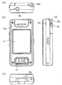
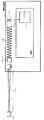
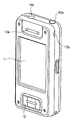
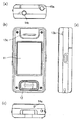
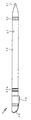
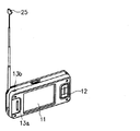
本発明の第1の実施形態としての携帯電話機1は、図1から図4に示すように、各種情報を表示すると共にタッチパネルとしての入力を受ける表示入力部11と、4方向キーによる入力など画面表示に応じてユーザからの各種の入力操作を受ける操作入力部12と、携帯電話としての通話を行うための通話用スピーカ13aおよび通話用マイク14aと、TV受信時などに離れたところでも音を聞けるようにするスピーカ13bと、外部マイクや外部スピーカを接続するための端子接続部14bとを備えると共に、TV受信用アンテナおよび表示入力部11への入力ペンとして機能するTVアンテナ兼入力ペン2が、携帯電話機1の装置本体に対して着脱可能に設けられて構成されている。
ここで、この携帯電話機1の装置本体とは、携帯電話機1からTVアンテナ兼入力ペン2を抜き取った残りの部分(携帯電話機1におけるTVアンテナ兼入力ペン2以外の部分)のことである。
[First Embodiment]
As shown in FIGS. 1 to 4, the
Here, the device main body of the
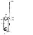
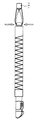
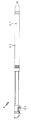
TVアンテナ兼入力ペン2は、装置本体に装着された状態で図3に例示するように伸長されることによりTV受信用アンテナの一部として機能すると共に、図4に例示するように装置本体から取り外されることで、表示入力部11への押圧による手入力を行うのに用いられる入力ペンとして機能する。
The TV antenna and
TVアンテナ兼入力ペン2は、図4、図5(a)、図6(a)に示すように、表示入力部11に接触して押圧による入力を行う先端部である入力先端部(接触入力部)21と、アンテナとして使用時に装置本体から不用意に抜けないよう抜け落ち防止固定するための凹部である本体固定部(移動ロック用凹部)22と、入力ペンとしてユーザが手で持つためのペン本体部23と、アンテナを伸縮操作しやすいようにするための凸部としてペン本体部23に設けられたアンテナ伸縮操作用凸部24と、アンテナを引き伸ばしたりといった伸縮操作を行うためのアンテナ伸縮操作部材(操作用部材)25と、伸長されることでWhip Rod式構造のTVアンテナとして機能する多段式アンテナ部26とを備えて構成される。
As shown in FIGS. 4, 5 (a), and 6 (a), the TV antenna /
入力先端部21は、装置本体から取り外されて入力ペンとして使用される際に表示入力部11に接触して押圧する部分である。この入力先端部21の材料は、本体固定部22やペン本体部23と共通する素材であってもよい。
The
アンテナ伸縮操作部材25には、装置本体への装着時にTVアンテナ兼入力ペン2の長手方向に装置本体内に押し込むための本体装着操作部(押下用部分)25aと、装置本体への装着時にアンテナを伸縮操作するためのアンテナ伸長操作用突起25bとが形成されている。
The antenna expansion /
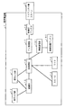
図7は、この携帯電話機1における制御のための構成を示すブロック図である。
この図7に示すように、本実施形態としての携帯電話機1は、上述した各構成に加え、入力された内容を認識する認識部15と、装置全体の制御を行う主制御部16と、TV受信部17と、装着部アンテナ18と、無線通信部191と、無線通信アンテナ192とを備えて構成される。
FIG. 7 is a block diagram showing a configuration for control in the
As shown in FIG. 7, in addition to the above-described components, the
認識部15は、圧力、静電気などのセンサーにより表示入力部11がタッチパネル表面への手書き入力動作の検出を行うと、その検出された入力情報を受けて入力された文字や数字の構造的な特徴を識別し、携帯電話機1内の文字・数字ライブラリに登録された文字・数字との照合、対応付けを行うことで、手書き動作の発生するタッチパネル上の位置情報を加え手書き入力操作の意味を解釈する。
When the
TV受信部17は、TV受信用アンテナにより受信されたTV信号からチャンネルの選択と映像および音声信号の復元を行う。
本携帯電話機1におけるTV受信用アンテナは、図7、図8に示すように、装着部アンテナ18とTVアンテナ兼入力ペン2とにより構成される。すなわち、TVアンテナ兼入力ペン2における多段式アンテナ部26は、TVアンテナ兼入力ペン2が装置本体に挿入された状態で、図9に示すようにアンテナ接続端子23aおよび装着部側接続端子181aを介して装着部アンテナ18に接続され、この装着部アンテナ18がTV受信部17に接続されて構成されていることにより、装着部アンテナ18およびTVアンテナ兼入力ペン2はTV受信用アンテナとして機能する。
The
As shown in FIGS. 7 and 8, the TV receiving antenna in the
TVアンテナ兼入力ペン2が装置本体に装着された際の多段式アンテナ部26と装着部アンテナ18との接続は、図9の拡大断面図に示すように、金属製の多段式アンテナ部26の外面がアンテナ接続端子23aの内面に接触するよう構成され、TVアンテナ兼入力ペン2が装置本体に装着された際にそのアンテナ接続端子23aが装着部181における金属部である装着部側接続端子181aに接触するよう構成されている。
この装着部側接続端子181aに接続された装着部アンテナ18が、反対側の端部で図8に示すようにTV受信部17に接続されることで、多段式アンテナ部26と装着部アンテナ18とがTV受信部17に接続され、TV受信用アンテナとして機能することとなる。
As shown in the enlarged sectional view of FIG. 9, the connection between the
The mounting
装着部アンテナ18は、図5(b)、図6(a)に示すように、TVアンテナ兼入力ペン2を装置本体に装着させるための装着部181外周に巻回されたコイルアンテナであり、TVアンテナ兼入力ペン2における多段式アンテナ部26に接続された状態でその多段式アンテナ部26の長さと合計されることでTV受信用アンテナとして最適な長さを確保できるようになっており、受信効率を向上させることができるようになっている。
The mounting
このTV受信用アンテナの適正長さは、VHFかUHFかなど各種の要因によって違ってくるが、その長さの微調整はユーザが多段式アンテナ部26を伸長/収縮させることにより行う。このことにより、電波受信状況に応じて最適な長さにアンテナを調整することができる。
最適長さの調整は、ユーザが表示入力部11に表示されるTV受信画面を見ることで行うこととしてもよく、表示入力部11に調整用のインジケータを表示させてもよい。また、ユーザによる伸長/収縮ではなく電動や固定式など、最適長さを得ることができれば各種の態様であってよい。
The appropriate length of the TV receiving antenna varies depending on various factors such as VHF or UHF, but the user finely adjusts the length by extending / contracting the
The adjustment of the optimum length may be performed by the user looking at the TV reception screen displayed on the
多段式アンテナ部26は、金属製の複数の円筒体が同心円状に伸縮可能に組み合わされて構成され、その同心円における最小半径の円筒体の先端部にアンテナ伸縮操作部材25が設けられている。また、その同心円における最大半径の円筒体外面が、上述のようにアンテナ接続端子23aの内面に接触するよう構成されている。
また、各円筒体が収縮されることで、TVアンテナ兼入力ペン2の円筒体部分であるペン本体部23に収納されることとなる。
The
Further, each cylindrical body is contracted, so that it is housed in the pen
入力先端部21、本体固定部22、ペン本体部23および装着部181は、プラスチックなどの絶縁体で構成されている。すなわち、TVアンテナ兼入力ペン2における入力先端部21と一体に構成された部分は、装着部アンテナ18および多段式アンテナ部26をTV受信用アンテナとして機能させるための接点部分であるアンテナ接続端子23a以外、絶縁体で構成されている。
このことによりTVアンテナ兼入力ペン2が外部から装置本体に挿入された際に不要な静電気が装置内部に持ち込まれてしまうことを極力防止することができる。
The
Thus, it is possible to prevent unnecessary static electricity from being brought into the apparatus when the TV antenna /
また、アンテナは上述したTV受信用と、携帯電話としての通話などTV受信以外の無線通信用の無線通信アンテナ192とで別々に設けられ、このことによりアンテナの最適長さが異なる両方の無線通信について良好な無線感度を確保できるようになっている。
無線通信部191は、主制御部16の制御下で無線通信アンテナ192によりデータの無線送受信を行うことで、通話機能、メール機能、データ通信機能など携帯電話機として公知の各種機能を実現させている。
In addition, the antenna is provided separately for the TV reception described above and the
The
TVアンテナ兼入力ペン2は、装置本体に装着されると図10に示すように、ラッチ機構を持ったラッチスイッチ182により図10における矢印方向(TVアンテナ兼入力ペン2の長手方向に対して略垂直な方向)に挟み込まれて固定されている。
このラッチスイッチ182は、図11に示すように、挟み用部材182b側の面の中央に設けられた押下スイッチ182aが押下される毎に挟み用部材182bが開状態と閉状態とを交互に切り換えられるよう構成されたものである。
When the TV antenna /
As shown in FIG. 11, the
TVアンテナ兼入力ペン2が装置本体に挿入され、最奥まで押し込まれて装着されると、開状態であるラッチスイッチ182の押下スイッチ182aを入力先端部21が押下することとなるため、ラッチスイッチ182が閉状態となり、TVアンテナ兼入力ペン2は本体固定部22の部分で挟み用部材182bにより図10に示すように矢印方向に挟み込まれることとなり、長手方向におけるスライド移動が制限されてアンテナ伸長などの各種操作が行われても不用意に抜け落ちることのないように装置本体に対して支持される。
When the TV antenna /
すなわち、このラッチスイッチ182は、上述のようにして閉状態になるとTVアンテナ兼入力ペン2を挟んで支持した状態で挟み用部材182bが固定されるよう構成されているため、閉状態では、TVアンテナ兼入力ペン2を装置本体内に押し込むことはできてもそのままTVアンテナ兼入力ペン2を抜き取ることはできないようになっている。
That is, the
こうしてTVアンテナ兼入力ペン2がラッチスイッチ182により挟んで支持されて装置本体に装着されたHOLD状態から、TVアンテナ兼入力ペン2が長手方向における装置本体の最奥側へ押し込まれると、閉状態であるラッチスイッチ182の押下スイッチ182aを入力先端部21が押下することとなるため、ラッチスイッチ182が開状態となり、上述した本体固定部22の部分での挟み用部材182bによるロックが解除される。同時に押下スイッチ182aが押し戻される反動でTVアンテナ兼入力ペン2が長手方向における装置外部側に押し出されるため、TVアンテナ兼入力ペン2の少なくとも一部が装置本体から外部にはじき出されることとなり、ユーザがTVアンテナ兼入力ペン2を引き出しやすい状態となる。
When the TV antenna /
次に、本実施形態としての携帯電話機1で、TV受信用アンテナを伸長させてTVを視聴したり入力ペンにより手書き入力を行うなどの各種操作を行うために、TVアンテナ兼入力ペン2を操作する際の動作について説明する。
Next, in the
まず、TV受信用アンテナとして使用する場合には、図12に示すように、爪先などでアンテナ伸長操作用突起25bに図12中の矢印方向に力Fを加えて引っ張り上げた後、アンテナ伸縮操作部材25を持ってスライドさせることにより、ペン本体部23内に収納された多段式アンテナ部26を伸長させる。
First, when used as a TV receiving antenna, as shown in FIG. 12, the
こうして多段式アンテナ部26が伸長されることにより、上述のようにアンテナ接続端子23aおよび装着部側接続端子181aを介して装着部アンテナ18に接続され、さらに装着部アンテナ18がTV受信部17に接続され、TVアンテナ兼入力ペン2および装着部アンテナ18からTV電波がTV受信部17に電送される。
ユーザがTV画面を見るための所要の操作を行い、表示入力部11にTV画面が表示されると、その表示状態に応じてユーザが多段式アンテナ部26の長さを調整することで、受信状態の調整を行うことができる。
By extending the
When the user performs a required operation for viewing the TV screen and the TV screen is displayed on the
また、入力ペンとして使用する場合は、図13に示すように、TVアンテナ兼入力ペン2における長手方向の先端部として装置本体から露出している本体装着操作部25aを指先で図13中の矢印方向(長手方向に装置本体内に向けて押し込む方向)に押下することにより、上述したラッチスイッチ182の機能によりHOLD状態(挟み用部材182bにロックされた状態)が解除されてTVアンテナ兼入力ペン2が押し出され、装置本体から抜き取ることができるようになる。
When used as an input pen, as shown in FIG. 13, the main body mounting
ここで、ラッチスイッチ182を押下する入力先端部21と一体に構成された部分は、TVアンテナ兼入力ペン2が装置本体に装着された状態では図1に示すようにアンテナ伸縮操作用凸部24しか装置外部に露出しておらず、そしてそのアンテナ伸縮操作用凸部24も挟んで持つことが不可能な1方向しか露出していないため、そのアンテナ伸縮操作用凸部24で押下することはユーザの通常操作としては行うことができないようになっている。
このため、上述のように図13中の矢印方向に押下することでラッチスイッチ182によるHOLD状態を解除してTVアンテナ兼入力ペン2を取り出すためには、ユーザの通常操作として、本体装着操作部25aを押し込む方向に押下せざるを得ない構成となっている。
Here, the portion integrated with the
Therefore, in order to release the HOLD state by the
すなわち、本実施形態としての携帯電話機は、ユーザが多段式アンテナ部26を収縮させて完全にペン本体部23に収納しない限り、TVアンテナ兼入力ペン2を装置本体から取り外すために押下することができない構成となっている。
このことにより、本実施形態によれば、TVアンテナ兼入力ペン2をTV受信用アンテナの一部として使用している時には不用意に抜けないようにすることができ、さらに手入力用の入力ペンとして使用する時には多段式アンテナ部26を収納した状態とさせることができる。
このため、TVアンテナ兼入力ペン2がTV受信用アンテナと入力ペンとの全く異なる機能を兼用した構成としながらも、ユーザが両機能を最適な状態で活用できるように自然に切り換えるようにさせることができる。
That is, the mobile phone according to the present embodiment can be pressed to remove the TV antenna /
Thus, according to the present embodiment, when the TV antenna /
For this reason, the TV antenna /
また、本実施形態によれば、以上のようにTVアンテナ兼入力ペン2がTV受信用アンテナと入力ペンとの全く異なる機能を兼用した構成とすることで、体積の大きいTV受信用アンテナと入力ペンとの両方でスペースをとることがないようにすることができ、装置本体内の空間を有効に利用することができる。
Also, according to the present embodiment, as described above, the TV antenna /
さらに、本実施形態によれば、TVアンテナ兼入力ペン2がTV受信用アンテナと入力ペンとを兼用する構成でありながらも、TV受信用アンテナとして使用する時にもアンテナ伸長操作用突起25bを引き上げることで伸長させることができ、入力ペンとして使用するために装置本体から抜き取るときにも押すだけで抜き取ることができるため、操作感にも優れたTVアンテナ兼入力ペンを備えた携帯電話機を提供することができる。
Furthermore, according to the present embodiment, the antenna
なお、上述した実施形態では、図4、図5(a)、図6(a)に示すようにアンテナ伸縮操作用凸部24がペン本体部23におけるアンテナ伸縮操作部材25側の端部に形成されることとして説明したが、アンテナ伸縮操作用凸部24はこの位置に限定されず、例えば図14に示すように多段式アンテナ部26のペン本体部23側の1節目(最も太い円筒体)におけるアンテナ伸縮操作部材25側の端部に配設されることとしてもよい。
すなわち、図14に示すように多段式アンテナ部26の最も太い1節目を伸長させた状態にしてもアンテナ伸縮操作用凸部24がアンテナ伸縮操作部材25側の端部にあるようにアンテナ伸縮操作用凸部24が配設されることとしてもよい。
この場合、金属製の多段式アンテナ部26に対して、その1節目(最も太い円筒体)のアンテナ伸縮操作部材25側の端部に樹脂製のアンテナ伸縮操作用凸部24を形成してもよい。
In the embodiment described above, the antenna expansion / contraction operation
That is, as shown in FIG. 14, even when the thickest first node of the
In this case, a resin antenna expansion / contraction operation
このように、アンテナ伸縮操作用凸部24を多段式アンテナ部26のペン本体部23側の1節目(最も太い円筒体)に配設することによれば、多段式アンテナ部26の最も太い1節目を伸長させた状態にしても手入力用の入力ペンとして好適に使用することができる。
このため、例えば装置本体が非常に小型化されているなどにより、TVアンテナ兼入力ペン2の長さを短くせざるを得ない場合であっても、入力ペンとして適度な長さを確保することができ、装置本体を小型化できると共に入力ペンとしての使用感も好適なものとすることができる。
Thus, by arranging the antenna expansion / contraction operation
For this reason, even when the length of the TV antenna /
〔第2の実施形態〕
次に、本発明の第2の実施形態について説明する。この第2の実施形態は、上述した第1の実施形態で、アンテナ伸長操作用突起25bを爪先などで引っかけてアンテナを伸長させているのに替えて、アンテナ伸縮操作部材が装置本体から外部に突出した構成としたものである。
このアンテナ伸縮操作部材周り以外については上述した第1の実施形態と同様の構成であり、説明を省略する。
[Second Embodiment]
Next, a second embodiment of the present invention will be described. This second embodiment is the same as the first embodiment described above, but instead of extending the antenna by hooking the antenna
Except for the area around the antenna expansion / contraction operation member, the configuration is the same as that of the first embodiment described above, and a description thereof will be omitted.
第2の実施形態としての携帯電話機では、図15、図16に示すように、TVアンテナ兼入力ペン3におけるアンテナ伸縮操作部材35が装置本体から外部に突出することで、アンテナ伸縮操作部材35を直接指先などでつまんで引き上げることが可能な構成となっている。
このTVアンテナ兼入力ペン3についても、アンテナ伸縮操作用凸部24が省略されていることおよびアンテナ伸縮操作部材35周り以外については上述した第1の実施形態と同様の構成であり、同様の部分については同符号として説明を省略する。
In the mobile phone as the second embodiment, as shown in FIGS. 15 and 16, the antenna expansion /
The TV antenna /
次に、TV受信用アンテナを伸長させてTVを視聴したり入力ペンにより手書き入力を行うなどの各種操作を行うために、TVアンテナ兼入力ペン3を操作する際の動作について説明する。
Next, the operation when operating the TV antenna /
まず、TV受信用アンテナとして使用する場合には、図17に示すように、指先でアンテナ伸縮操作部材35におけるアンテナ伸長操作部35bを直接つまむことで図17中の矢印方向に力Fを加えて引っ張り上げてスライドさせることにより、ペン本体部23内に収納された多段式アンテナ部26を伸長させる。
First, when used as a TV receiving antenna, as shown in FIG. 17, a force F is applied in the direction of the arrow in FIG. 17 by directly pinching the antenna
こうして多段式アンテナ部26が伸長されることにより、上述した第1の実施形態と同様にアンテナ接続端子23aおよび装着部側接続端子181aを介して装着部アンテナ18に接続され、さらに装着部アンテナ18がTV受信部17に接続され、TVアンテナ兼入力ペン3および装着部アンテナ18からTV電波がTV受信部17に電送される。
ユーザがTV画面を見るための所要の操作を行い、表示入力部11にTV画面が表示されると、その表示状態に応じてユーザが多段式アンテナ部26の長さを調整することで、受信状態の調整を行うことができる。
By extending the
When the user performs a necessary operation for viewing the TV screen and the TV screen is displayed on the
また、入力ペンとして使用する場合は、図18に示すように、TVアンテナ兼入力ペン3における長手方向の先端部である本体装着操作部35aを指先で図18中の矢印方向(長手方向に装置本体内に向けて押し込む方向)に押下することにより、上述した第1の実施形態と同様のラッチスイッチ182の機能により装置本体のHOLD状態(挟み用部材182bにロックされた状態)が解除されてTVアンテナ兼入力ペン3が押し出され、装置本体から抜き取ることができるようになる。
Further, when used as an input pen, as shown in FIG. 18, the main body mounting
ここで、ラッチスイッチ182を押下する入力先端部21に対してアンテナ伸縮による移動をしない部分は、TVアンテナ兼入力ペン3が装置本体に装着された状態では装置外部に露出されていないため、上述のように図18中の矢印方向に押下することでラッチスイッチ182によるHOLD状態を解除してTVアンテナ兼入力ペン2を取り出すためには、ユーザの通常操作として、本体装着操作部25aを押し込む方向に押下せざるを得ない構成となっている。
Here, the portion that does not move due to the expansion / contraction of the antenna with respect to the input
換言すれば、ユーザは多段式アンテナ部26を収縮させて完全にペン本体部23に収納しない限り、TVアンテナ兼入力ペン3を装置本体から取り外すために押下することができない構成となっている。
このことにより、この第2の実施形態によれば、TVアンテナ兼入力ペン3をTV受信用アンテナの一部として使用している時には不用意に抜けないようにすることができ、さらに入力ペンとして使用する時には多段式アンテナ部26を収納した状態とさせることができる。
このため、TVアンテナ兼入力ペン2がTV受信用アンテナと入力ペンとの全く異なる機能を兼用した構成としながらも、ユーザが両機能を最適な状態で活用できるように自然に切り換えるようにさせることができる。
In other words, the user cannot depress the TV antenna /
Thus, according to the second embodiment, when the TV antenna /
For this reason, the TV antenna /
また、本実施形態によれば、以上のようにTVアンテナ兼入力ペン3がTV受信用アンテナと入力ペンとの全く異なる機能を兼用した構成とすることで、体積の大きいTV受信用アンテナと入力ペンとの両方でスペースをとることがないようにすることができ、装置本体内の空間を有効に利用することができる。
In addition, according to the present embodiment, as described above, the TV antenna /
さらに、本実施形態によれば、TVアンテナ兼入力ペン3がTV受信用アンテナと入力ペンとを兼用する構成でありながらも、TV受信用アンテナとして使用する時にアンテナ伸縮操作部材35を指先で直接つまんで引き上げるだけでアンテナを伸長させることができ、入力ペンとして使用するために装置本体から抜き取るときにも押すだけで抜き取ることができるため、操作感にも優れたTVアンテナ兼入力ペンを備えた携帯電話機を提供することができる。
Furthermore, according to the present embodiment, although the TV antenna /
〔第3の実施形態〕
次に、本発明の第3の実施形態について説明する。この第3の実施形態は、上述した第1の実施形態で、アンテナ伸長操作用突起25bを爪先などで引っかけてアンテナを伸長させているのに替えて、アンテナ伸縮操作部材の上部である本体装着操作部のみが装置本体から外部に露出した構成としたものである。
このアンテナ伸縮操作部材周り以外については上述した第1の実施形態と同様の構成であり、説明を省略する。
[Third Embodiment]
Next, a third embodiment of the present invention will be described. This third embodiment is the same as the first embodiment described above, except that the antenna is extended by hooking the antenna
Except for the area around the antenna expansion / contraction operation member, the configuration is the same as that of the first embodiment described above, and a description thereof will be omitted.
第3の実施形態としての携帯電話機では、図19、図20に示すように、TVアンテナ兼入力ペン4におけるアンテナ伸縮操作部材45の上部である本体装着操作部45aのみが装着時に装置本体から外部に露出した構成となり、突起や凹凸部の少ない外観となっている。
このTVアンテナ兼入力ペン4についても、アンテナ伸縮操作用凸部24が省略されていることおよびアンテナ伸縮操作部材45周り以外については上述した第1の実施形態と同様の構成であり、同様の部分については同符号として説明を省略する。
In the mobile phone as the third embodiment, as shown in FIGS. 19 and 20, only the main body mounting
The TV antenna /
次に、TV受信用アンテナを伸長させてTVを視聴したり手入力用の入力ペンにより手書き入力を行うなどの各種操作を行うために、TVアンテナ兼入力ペン4を操作する際の動作について説明する。
Next, the operation when operating the TV antenna /
TV受信用アンテナとして使用する場合には、図21(a)に示すように、まず指先でアンテナ伸縮操作部材45における本体装着操作部45aを図21(a)中の矢印方向(長手方向に装置本体内に向けて押し込む方向)に押下することにより、TVアンテナ兼入力ペン4における長手方向の先端部としての本体装着操作部45aから上述した第1の実施形態と同様のラッチスイッチ182に力Fが加えられ、そのラッチスイッチ182の機能により装置本体のHOLD状態(挟み用部材182bにロックされた状態)が解除されてTVアンテナ兼入力ペン4が押し出される。
When used as a TV receiving antenna, as shown in FIG. 21 (a), first, the main body mounting
こうして押し出されたアンテナ伸長操作部45bを、図21(b)に示すように指で直接つまむことでTVアンテナ兼入力ペン4を装置本体から抜き取り、図21(c)に示すように多段式アンテナ部26を伸長させる。
そうして多段式アンテナ部26が伸長された状態のTVアンテナ兼入力ペン4を、図21(d)に示すように再度装置本体に挿入して図21(d)中の矢印方向に押し込むことでTVアンテナ兼入力ペン4が装置本体に装着される。
The antenna
Then, the TV antenna /
こうして多段式アンテナ部26が伸長されたTVアンテナ兼入力ペン4が装置本体に装着されることにより、その多段式アンテナ部26が上述した第1の実施形態と同様にアンテナ接続端子23aおよび装着部側接続端子181aを介して装着部アンテナ18に接続され、さらに装着部アンテナ18がTV受信部17に接続され、TVアンテナ兼入力ペン4および装着部アンテナ18からTV電波がTV受信部17に電送される。
ユーザがTV画面を見るための所要の操作を行い、表示入力部11にTV画面が表示されると、その表示状態に応じてユーザが多段式アンテナ部26の長さを調整することで、受信状態の調整を行うことができる。
When the TV antenna /
When the user performs a necessary operation for viewing the TV screen and the TV screen is displayed on the
また、入力ペンとして使用する場合は、図21(a)(b)を用いて上述したようにしてTVアンテナ兼入力ペン4を装置本体から抜き取ることで、そのまま手入力用の入力ペンとして使用することができる。
When used as an input pen, the TV antenna /
以上のように、この第3の実施形態においても、TVアンテナ兼入力ペン4における長手方向の先端部である本体装着操作部45aを指先で押下することによりTVアンテナ兼入力ペン4を装置本体から抜き取るため、ユーザが多段式アンテナ部26を収縮させて完全にペン本体部23に収納しない限り、TVアンテナ兼入力ペン3を装置本体から取り外すために押下することができない構成となっている。
As described above, also in the third embodiment, the TV antenna /
このことにより、本実施形態によれば、TVアンテナ兼入力ペン4をTV受信用アンテナの一部として使用している時には不用意に抜けないようにすることができ、さらに入力ペンとして使用する時には多段式アンテナ部26を収納した状態とさせることができる。
このため、TVアンテナ兼入力ペン2がTV受信用アンテナと入力ペンとの全く異なる機能を兼用した構成としながらも、ユーザが両機能を最適な状態で活用できるように自然に切り換えるようにさせることができる。
Thus, according to the present embodiment, when the TV antenna /
For this reason, the TV antenna /
また、本実施形態によれば、以上のようにTVアンテナ兼入力ペン4がTV受信用アンテナと入力ペンとの全く異なる機能を兼用した構成とすることで、体積の大きいTV受信用アンテナと入力ペンとの両方でスペースをとることがないようにすることができ、装置本体内の空間を有効に利用することができる。
Also, according to the present embodiment, as described above, the TV antenna /
さらに、本実施形態によれば、TVアンテナ兼入力ペン4がTV受信用アンテナと入力ペンとを兼用する構成でありながらも、本体装着操作部45aを指先で押下するだけでTVアンテナ兼入力ペン4を抜き取ることができ操作感にも優れると共に、携帯電話機を突起や凹凸部の少ないスッキリとした外観とすることができる。
Furthermore, according to the present embodiment, even though the TV antenna /
〔第4の実施形態〕
次に、本発明の第4の実施形態について説明する。この第4の実施形態は、上述した第1、第2の実施形態で、TVアンテナ兼入力ペンを装置本体から抜き取った状態であっても多段式アンテナ部を伸長させることは自由にできる構成となっているのに替えて、TVアンテナ兼入力ペンを装置本体から抜き取って入力ペンとして使用する場合には多段式アンテナ部を伸長させることができない構成としたものである。
上述した第1の実施形態と同様の構成については同符号とし、説明を省略する。
[Fourth Embodiment]
Next, a fourth embodiment of the present invention will be described. The fourth embodiment is a configuration in which the multistage antenna unit can be freely extended even when the TV antenna / input pen is removed from the apparatus main body in the first and second embodiments described above. Instead of this, when the TV antenna / input pen is removed from the apparatus main body and used as an input pen, the multistage antenna unit cannot be extended.
The same components as those in the first embodiment described above are denoted by the same reference numerals, and description thereof is omitted.
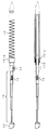
第4の実施形態としての携帯電話機では、図22に示すように、TVアンテナ兼入力ペン5の側面にロック解除穴57が開設されている。
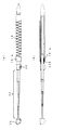
また、図23に示すように、ペン本体部23内部における多段式アンテナ部26を収納している部分に、多段式アンテナ部26の最先端節(最も細い円筒体)のスライド移動をロックするアンテナ固定用バネ58が配設されている。
In the mobile phone as the fourth embodiment, as shown in FIG. 22, a lock release hole 57 is formed on the side surface of the TV antenna and
Further, as shown in FIG. 23, the antenna that locks the sliding movement of the most advanced node (the thinnest cylindrical body) of the
このアンテナ固定用バネ58は、ペン本体部23の内側面に配設され、弾性による復元力がその円筒体内側の半径方向中心側に向かうようチャージ(付勢;復元力を蓄える)された板バネである。この付勢により、TVアンテナ兼入力ペン5が装置本体から取り出されている状態では、多段式アンテナ部26の最先端節(最も細い円筒体)における最奥部近傍に設けられた固定用凹部にアンテナ固定用バネ58の端部が押圧されて押し付けられる。
このことにより、多段式アンテナ部26の最先端節はスライド移動がロックされ、したがってユーザは多段式アンテナ部26を伸長させることができなくなる。
The antenna fixing spring 58 is disposed on the inner side surface of the pen
As a result, the slide movement of the most advanced node of the
また、TVアンテナ兼入力ペン5が装置本体に装着された時には、ロック解除部材183により、多段式アンテナ部26と同心の円筒体であるペン本体部23の半径方向外側にアンテナ固定用バネ58が押圧され、このことによりアンテナ固定用バネ58の端部が多段式アンテナ部26の最先端節の固定用凹部から外れてロックが解除される。
このため、TVアンテナ兼入力ペン5が装置本体に装着された状態では、ユーザは多段式アンテナ部26を自在に伸長させることができる。
When the TV antenna /
For this reason, in a state where the TV antenna and
ロック解除部材183は、図24に示すように、回転軸183aにより装置本体に回転動作可能に支持され、ロック解除穴57への挿入部分(解除側端部)がTVアンテナ兼入力ペン5から離れる方向へと弾性による復元力が向かうよう、バネ183bによりチャージ(付勢)されている。
As shown in FIG. 24, the unlocking
ここで、図24(a)に示すように、回転軸183aが解除側端部およびその解除側端部でない他端より内側に設けられているため、TVアンテナ兼入力ペン5が装置本体に装着される時には、そのTVアンテナ兼入力ペン5の先端部分によりロック解除部材183の解除側端部でない他端に対して図24(a)中の矢印方向に力Fが加えられ、その力Fによりロック解除部材183が回転軸183aを中心として回転し、その回転動作によってロック解除部材183におけるロック解除穴57への挿入部分(解除側端部)がTVアンテナ兼入力ペン5の方に移動する。こうしてロック解除部材183におけるロック解除穴57への挿入部分がロック解除穴57から挿入され、この挿入部分によりアンテナ固定用バネ58が上述のように円筒体であるペン本体部23内部の半径方向外側に押圧され、ロックが解除される。
Here, as shown in FIG. 24 (a), since the
上述したラッチスイッチ182は、上述のようにTVアンテナ兼入力ペン5が装置本体に装着された状態で、ロック解除部材183の回転による移動平面と重ならない平面で挟み用部材182bにより本体固定部22を挟んで支持するように配設される。
The above-described
また、図24(b)に示すように、TVアンテナ兼入力ペン5が装置本体から抜き取られるときには、バネ183bにより、ロック解除部材183におけるロック解除穴57への挿入部分がTVアンテナ兼入力ペン5から離れる方向へと引っ張られ、このことにより挿入部分がロック解除穴57から抜け、アンテナ固定用バネ58の復元力によりロックがかかると共に、TVアンテナ兼入力ペン5がスムーズに抜き取られる。
Further, as shown in FIG. 24B, when the TV antenna /
以上のように、この第4の実施形態によれば、TVアンテナ兼入力ペン5が装置本体に装着されている時にはアンテナ固定用バネ58によるロックが解除され、多段式アンテナ部26をユーザが自在に伸縮させることができると共に、TVアンテナ兼入力ペン5が装置本体から抜き取られて入力ペンとして使用される時にはアンテナ固定用バネ58によるロックがかかり、多段式アンテナ部26をユーザが伸長させることができないようにすることができる。
As described above, according to the fourth embodiment, when the TV antenna /
このため、TVアンテナ兼入力ペン5がTV受信用アンテナと入力ペンとの全く異なる機能を兼用した構成としながらも、ユーザが何れの機能をも最適な状態で活用できるようにさせることができる。
また、このようにTVアンテナ兼入力ペン5を入力ペンとして使用する際の不必要な伸縮動作を制限することができるため、ユーザの操作性を向上させることができると共に、不必要な伸長による破損事故などを未然に防止することができる。
Therefore, it is possible to allow the user to utilize any function in an optimum state while the TV antenna /
In addition, since the unnecessary telescopic operation when the TV antenna /
さらに、上述した第1または第2の実施形態と同様に、ユーザが多段式アンテナ部26を収縮させて完全にペン本体部23に収納しない限り、TVアンテナ兼入力ペン5を装置本体から取り外すために押下することができない構成となっているため、TVアンテナ兼入力ペン5をTV受信用アンテナの一部として使用している時には不用意に抜けないようにすることができる。
このため、TVアンテナ兼入力ペン5がTV受信用アンテナと入力ペンとの何れの機能として使用される際にも不用意に抜けたり不必要に伸長されたりといったことをなくすことができ、何れの機能として使用される際にも最適な使用状態をユーザに提供することができる。
Further, as in the first or second embodiment described above, the TV antenna /
For this reason, when the TV antenna /
〔第5の実施形態〕
次に、本発明の第5の実施形態について説明する。この第5の実施形態は、上述した第4の実施形態で、TVアンテナ兼入力ペンを装置本体から抜き取って入力ペンとして使用する場合には多段式アンテナ部を全く伸長させることができない構成としているのに替えて、入力ペンとして使用する場合にも1節のみ伸長させることができるようにしたものである。
上述した第1、第4の実施形態と同様の構成については同符号とし、説明を省略する。
[Fifth Embodiment]
Next, a fifth embodiment of the present invention will be described. In the fifth embodiment, when the TV antenna / input pen is extracted from the apparatus main body and used as the input pen, the multistage antenna unit cannot be extended at all. Instead of this, only one clause can be extended when used as an input pen.
The same components as those in the first and fourth embodiments described above are denoted by the same reference numerals, and description thereof is omitted.
第5の実施形態としての携帯電話機では、図22により上述したように、TVアンテナ兼入力ペン6の側面にロック解除穴67が開設され、このロック解除穴67により、図25に示すようにロック解除部材183が多段式アンテナ部26における1節目(最も太い円筒体)の内側に入るよう構成されている。
In the mobile phone as the fifth embodiment, as described above with reference to FIG. 22, the unlocking hole 67 is formed on the side surface of the TV antenna /
また、図25に示すように、多段式アンテナ部26における1節目(最も太い円筒体)の内側面に、多段式アンテナ部26の最先端節(最も細い円筒体)のスライド移動をロックするアンテナ固定用バネ68が配設されている。
Further, as shown in FIG. 25, the antenna that locks the sliding movement of the most advanced node (thinnest cylindrical body) of the
このアンテナ固定用バネ68は、多段式アンテナ部26の1節目(最も太い円筒体)内側面の半径方向中心側に向かってチャージ(付勢)された板バネである。この板バネの付勢により、TVアンテナ兼入力ペン6が装置本体から取り出されている状態では、多段式アンテナ部26の最先端節(最も細い円筒体)における最奥部近傍に設けられた固定用凹部にアンテナ固定用バネ68の端部が押圧されて押し付けられる。
The
このことにより、TVアンテナ兼入力ペン6が装置本体から取り出されて入力ペンとして使用される場合には、多段式アンテナ部26の最先端節はスライド移動がロックされ、したがってユーザは多段式アンテナ部26を1節目(最も太い円筒体)以外、伸長させることができなくなる。
すなわち、図26に示すように、ユーザは多段式アンテナ部26をペン本体部23側の1節目のみ伸長させて入力ペンとして使用することができ、他の節の伸長をロックすることができる。
As a result, when the TV antenna /
That is, as shown in FIG. 26, the user can use the
また、本実施形態におけるTVアンテナ兼入力ペン6では、図26に示すように、アンテナ伸縮操作用凸部24が多段式アンテナ部26の1節目(最も太い円筒体)におけるアンテナ伸縮操作部材25側の端部に配設される。
この場合、金属製の多段式アンテナ部26に対して、その1節目(最も太い円筒体)のアンテナ伸縮操作部材25側の端部に樹脂製のアンテナ伸縮操作用凸部24を形成してもよい。
Further, in the TV antenna /
In this case, a resin antenna expansion / contraction operation
また、TVアンテナ兼入力ペン6が装置本体に装着された時には、ロック解除部材183により、アンテナ固定用バネ68が多段式アンテナ部26の1節目(最も太い円筒体)内側面の半径方向外側に押圧され、このことによりアンテナ固定用バネ68の端部が多段式アンテナ部26の最先端節の固定用凹部から外れてロックが解除される。
このため、TVアンテナ兼入力ペン6が装置本体に装着された状態では、ユーザは多段式アンテナ部26を自在に伸長させることができる。
When the TV antenna /
For this reason, in a state where the TV antenna and
以上のように、この第5の実施形態によれば、TVアンテナ兼入力ペン6が装置本体に装着されている時にはアンテナ固定用バネ68によるロックが解除され、多段式アンテナ部26をユーザが自在に伸縮させることができると共に、TVアンテナ兼入力ペン6が装置本体から抜き取られて入力ペンとして使用される時にはアンテナ固定用バネ68によるロックがかかり、多段式アンテナ部26をユーザが1節目(最も太い円筒体)以外、伸長させることができないようにすることができる。
As described above, according to the fifth embodiment, when the TV antenna /
このように、多段式アンテナ部26をペン本体部23側の1節目のみ伸長させて入力ペンとして使用することができるように構成されているため、例えば装置本体が非常に小型化されているなどにより、TVアンテナ兼入力ペン2の長さを短くせざるを得ない場合であっても、入力ペンとして適度な長さを確保することができ、装置本体を小型化できると共に入力ペンとしての使用感も好適なものとすることができる。
Thus, since the
このため、TVアンテナ兼入力ペン6がTV受信用アンテナと入力ペンとの全く異なる機能を兼用した構成としながらも、入力ペンとして適度な長さを確保するよう調節することができることも含め、ユーザが何れの機能をも最適な状態で活用できるようにさせることができる。
For this reason, the user can also adjust the TV antenna /
また、このようにTVアンテナ兼入力ペン6を入力ペンとして使用する際の伸縮動作を1節目のみとすることができるため、不必要な伸縮動作を制限してユーザの操作性を向上させることができると共に、不必要な伸長による破損事故などを未然に防止することができる。
In addition, since the telescopic operation when the TV antenna /
さらに、上述した第1または第2の実施形態と同様に、ユーザが多段式アンテナ部26を収縮させて完全にペン本体部23に収納しない限り、TVアンテナ兼入力ペン6を装置本体から取り外すために押下することができない構成となっているため、TVアンテナ兼入力ペン6をTV受信用アンテナの一部として使用している時には不用意に抜けないようにすることができる。
このため、TVアンテナ兼入力ペン6がTV受信用アンテナと入力ペンとの何れの機能として使用される際にも不用意に抜けたり不必要に伸長されたりといったことをなくすことができ、何れの機能として使用される際にも最適な使用状態をユーザに提供することができる。
Furthermore, as in the first or second embodiment described above, the TV antenna /
For this reason, when the TV antenna /
なお、上述した第5の実施形態では、アンテナ固定用バネ68が多段式アンテナ部26の1節目(最も太い円筒体)内側面に設けられることとして説明したが、多段式アンテナ部を構成する複数の円筒体の何れかの内側面であれば他の節(円筒体)に設けられても本発明は同様に実現することができる。
この場合、アンテナ固定用バネ68が配置された円筒体よりも1つ細い円筒体より先端側の円筒体のスライド移動をロックすることとなる。
In the fifth embodiment described above, the
In this case, the sliding movement of the cylinder on the tip side of the cylinder that is one narrower than the cylinder on which the
〔第6の実施形態〕
次に、本発明の第6の実施形態について説明する。この第6の実施形態は、上述した第1の実施形態としての携帯電話機の構成に加え、TVアンテナ兼入力ペンにおける多段式アンテナ部を装置本体に対して回転動作自在とさせるヒンジ部を設けたものである。
上述した第1の実施形態と同様の構成については同符号とし、説明を省略する。
[Sixth Embodiment]
Next, a sixth embodiment of the present invention will be described. In addition to the configuration of the mobile phone as the first embodiment described above, the sixth embodiment is provided with a hinge portion that allows the multistage antenna portion of the TV antenna / input pen to rotate with respect to the apparatus main body. Is.
The same components as those in the first embodiment described above are denoted by the same reference numerals, and description thereof is omitted.
第6の実施形態としての携帯電話機では、図27から図29に示すように、TVアンテナ兼入力ペン7の多段式アンテナ部76にヒンジ部79が設けられている。
このヒンジ部79は、TVアンテナ兼入力ペン7が装置本体に装着されてTVアンテナとして利用される場合に、図27に示すように装置本体にぶつからない範囲で3次元空間における3自由度に対して多段式アンテナ部76を回転動作自在とさせるものである。
In the mobile phone as the sixth embodiment, as shown in FIGS. 27 to 29, a
When the TV antenna /
このようにヒンジ部79が設けられることにより、ユーザにとってTVアンテナによるTV信号の受信状態を調整しやすくするよう調整の自由度を高めることができる。
また、TVアンテナ兼入力ペン7によりTV信号の受信状態調整の自由度が高まることにより、装置本体を比較的自由に設置できるため、例えば図30に示すように表示入力部11を横にするように設置しても、多段式アンテナ部76の角度調整によるTV信号の受信状態調整を容易とすることができる。
By providing the
Further, since the degree of freedom in adjusting the reception state of the TV signal by the TV antenna /
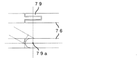
ヒンジ部79は、図27、図28に示すように、多段式アンテナ部76が伸長されて装置本体から外部に露出する部分に設けられる。また、図29に示すように、ヒンジ部79の中心79aを中心として多段式アンテナ部76が屈曲すると共に、TVアンテナ兼入力ペン7の長手方向を中心軸として自在に回転可能となるように多段式アンテナ部76がペン本体部23内側に連結されているため、ヒンジ部79もTVアンテナ兼入力ペン7の長手方向を中心軸として自在に回転可能となっている。
このことにより、多段式アンテナ部76におけるヒンジ部79より先端側の部分は、装置本体にぶつからない範囲で3次元空間における3自由度に対して回転動作自在となっている。
As shown in FIGS. 27 and 28, the
As a result, a portion of the
また、上述した第1の実施形態と同様に多段式アンテナ部76の伸長/収縮による受信状態調整も可能であるため、本実施形態におけるTVアンテナ兼入力ペン7がTVアンテナとして使用される場合には、アンテナ長さの伸縮および方向変更の両方によりTV電波受信状態の調整を行うことができるようになっている。
In addition, since the reception state can be adjusted by expanding / contracting the
また、ヒンジ部79は多段式アンテナ部76と同様に導電性材料によって構成されているため、本実施形態におけるTVアンテナ兼入力ペン7がTVアンテナとして使用される場合、図27、図28に示すように、上述した第1の実施形態と同様、多段式アンテナ部76はアンテナ接続端子23aおよび装着部側接続端子181aを介して装着部アンテナ18に接続され、この装着部アンテナ18がTV受信部17に接続されて構成されていることにより、装着部アンテナ18およびTVアンテナ兼入力ペン7はTV受信用アンテナとして機能する。
Moreover, since the
TVアンテナ兼入力ペン7を入力ペンとしてユーザが使用する場合には、上述した第1の実施形態と同様に、多段式アンテナ部76が収縮された状態で本体装着操作部25aをTVアンテナ兼入力ペン7の長手方向に装置本体内に向けて押し込む方向に指先で押下することにより、上述したラッチスイッチ182の機能により装置本体のHOLD状態(挟み用部材182bにロックされた状態)を解除し、装置本体から抜き取ることとなる。
When the user uses the TV antenna /
ここで仮に、屈曲させたヒンジ部79をユーザが装置本体内に押し込むことでラッチスイッチ182によるHOLD状態を解除し、TVアンテナ兼入力ペン7を装置本体から抜き取ろうと試みたとしても、上述のようにヒンジ部79は、多段式アンテナ部76が伸長されて装置本体から外部に露出する部分に設けられているため、屈曲させたヒンジ部79を装置本体内に押し込んでも多段式アンテナ部76が収縮されることとなり、従ってラッチスイッチ182によるHOLD状態を解除することはできないようになっている。
このため、TVアンテナ兼入力ペン7が装置本体に装着された状態から、ラッチスイッチ182によるHOLD状態を解除してTVアンテナ兼入力ペン7を装置本体から抜き取るためには、多段式アンテナ部76を収縮させてペン本体部23内部に完全に収納し、それから上述のように本体装着操作部25aを装置本体内に向けて押し込むこととなる。
Here, even if the user presses the
Therefore, in order to release the HOLD state by the
以上のように、本実施形態によれば、TVアンテナ兼入力ペン7によるTV信号の受信状態調整を、装置本体にぶつからない範囲で3次元空間における3自由度に対して自在に行うことができる。このことにより、装置本体の設置状態などにおける自由度も向上させることができ、ユーザの使用感、操作性を向上させることができる。
As described above, according to the present embodiment, the reception state adjustment of the TV signal by the TV antenna /
また同時に、上述した第1の実施形態と同様に、TV受信用アンテナとして使用している時にはラッチスイッチ182により不用意に抜けないようにすることができ、さらに手入力用の入力ペンとして使用する時には多段式アンテナ部26を収納した状態とさせることができる。
このため、上述した第1の実施形態により得られる効果と同様の効果をも併せて得ることができる。
At the same time, as in the first embodiment described above, when used as a TV receiving antenna, it can be prevented from being inadvertently removed by the
For this reason, the effect similar to the effect acquired by 1st Embodiment mentioned above can also be acquired collectively.
なお、上述した第6の実施形態では、ヒンジ部79は、多段式アンテナ部76が伸長されて装置本体から外部に露出する根本の部分に設けられることとして説明したが、多段式アンテナ部76を3次元空間における3自由度に対して回転動作自在とすることにより調整の自由度を向上させることができればこの位置に限定されず、装置本体の形状などに応じて各種の位置に設けられるものであってもよい。
In the sixth embodiment described above, the
また、アンテナ伸縮操作用凸部24は、上述した第1の実施形態と同様に、ペン本体部23におけるアンテナ伸縮操作部材25側の端部の位置に限定されず、多段式アンテナ部76のペン本体部23側の1節目(最も太い円筒体)におけるアンテナ伸縮操作部材25側の端部に配設されることとしてもよい。
この場合、ユーザがTVアンテナ兼入力ペン7を入力ペンとして使用する時には、上述のようにしてTVアンテナ兼入力ペン7を装置本体から抜き取った後、多段式アンテナ部76のペン本体部23側の1節目を伸長させることで最適な長さとして使用することとなる。
このことによれば、例えば装置本体が非常に小型化されているなどにより、TVアンテナ兼入力ペンの長さを短くせざるを得ない場合であっても、入力ペンとして適度な長さを確保することができ、装置本体を小型化できると共に入力ペンとしての使用感も好適なものとすることができ、設計の自由度を向上させることができる。
Further, the antenna expansion / contraction operation
In this case, when the user uses the TV antenna /
According to this, even if the length of the TV antenna and input pen has to be shortened due to, for example, the device body being very small, an appropriate length is secured as the input pen. In addition, the apparatus main body can be reduced in size and the usability as an input pen can be improved, and the degree of freedom in design can be improved.
また、上述した第6の実施形態では、上述した第1の実施形態にヒンジ部を設ける構成として説明したが、上述した第2から第5の実施形態にヒンジ部を設ける構成としても、同様に実現することができる。
このことによれば、それぞれの実施形態に適用した場合について、TVアンテナ兼入力ペンによるTV信号の受信状態調整を、装置本体にぶつからない範囲で3次元空間における3自由度に対して自在に行うことができ、装置本体の設置状態などにおける自由度も向上させることができ、ユーザの使用感、操作性を向上させることができる。
Further, in the above-described sixth embodiment, the configuration in which the hinge portion is provided in the above-described first embodiment has been described. However, the configuration in which the hinge portion is provided in the above-described second to fifth embodiments is the same. Can be realized.
According to this, when applied to each embodiment, the reception state adjustment of the TV signal by the TV antenna / input pen is freely performed with respect to the three degrees of freedom in the three-dimensional space as long as it does not hit the apparatus main body. In addition, the degree of freedom in the installation state of the apparatus main body can be improved, and the user's feeling of use and operability can be improved.
〔第7の実施形態〕
次に、本発明の第7の実施形態について説明する。この第7の実施形態は、上述した第1の実施形態としての携帯電話機の構成に加え、TVアンテナ兼入力ペンが装置本体に装着されているか否かを検知する装着状態検知スイッチを設けたものである。
上述した第1の実施形態と同様の構成については同符号とし、説明を省略する。
[Seventh Embodiment]
Next, a seventh embodiment of the present invention will be described. In the seventh embodiment, in addition to the configuration of the mobile phone as the first embodiment described above, a mounting state detection switch for detecting whether or not the TV antenna and input pen is mounted on the apparatus main body is provided. It is.
The same components as those in the first embodiment described above are denoted by the same reference numerals, and description thereof is omitted.
第7の実施形態としての携帯電話機では、図31に示すように、装着部181外周部における抜き出し口近辺に装着状態検知スイッチ184が設けられ、TVアンテナ兼入力ペン2が装置本体の装着部181に装着されているか否かを検知する。
この装着状態検知スイッチ184は、装着部181の外周部から内側に向けて検知用の突起部を挿入するよう構成され、TVアンテナ兼入力ペン2が装置本体に挿入されるとこの検知用の突起部を装着部181の半径方向外側に押し上げるため、その検知用突起の状態により挿入された状態となったことを検知する。
In the mobile phone as the seventh embodiment, as shown in FIG. 31, a mounting state detection switch 184 is provided near the outlet in the outer peripheral portion of the mounting
The wearing state detection switch 184 is configured to insert a detection projection from the outer periphery of the mounting
次に、本実施形態としての携帯電話機によりユーザがTVを視聴する場合に、装着状態検知スイッチ184による検知結果を用いて本携帯電話機がTVアンテナ状態に関する適切な操作メッセージを表示する動作について、図32のフローチャートを参照して説明する。 Next, when the user views the TV using the mobile phone according to the present embodiment, an operation in which the mobile phone displays an appropriate operation message regarding the TV antenna state using the detection result by the mounting state detection switch 184 is illustrated in FIG. This will be described with reference to the flowchart of FIG.
主制御部16がTV受信処理を開始すると、TV受信部17から送信されてきたTV信号レベルを検出し(ステップS1)、検出されたTV信号の強度が弱くない(予め設定された閾値よりも高い)場合、「TVアンテナ兼入力ペンの装着状態をチェック」に関するメッセージは出さず、TV画面を情報表示部11に表示させる(ステップS2)。
When the main control unit 16 starts the TV receiving process, the TV signal level transmitted from the
上述したステップS1の処理で検出されたTV信号レベルが弱い(予め設定された閾値よりも低い)場合、主制御部16は、装着状態検出スイッチ184によるTVアンテナ兼入力ペン2の装着状態検知結果を参照する。
検知結果が「装着されている」である場合(ステップS3;Yes)、例えば図33(a)に示すように、ユーザにTVアンテナによる受信状態のチェックを促すメッセージを、主制御部16は表示入力部11に表示させる。
検知結果が「装着されていない」である場合(ステップS3;No)、例えば図33(b)に示すように、ユーザにTVアンテナ兼入力ペン2の装着を促すメッセージを、主制御部16は表示入力部11に表示させる。
When the TV signal level detected in the process of step S1 described above is weak (lower than a preset threshold value), the main control unit 16 detects the mounting state detection result of the TV antenna /
If the detection result is “attached” (step S3; Yes), for example, as shown in FIG. 33A, the main control unit 16 displays a message prompting the user to check the reception state by the TV antenna. It is displayed on the
When the detection result is “not worn” (step S3; No), for example, as shown in FIG. 33 (b), the main control unit 16 sends a message prompting the user to wear the TV antenna /
以上のように、上述した第7の実施形態によれば、装着状態検出スイッチ184を備えることにより、TVアンテナ兼入力ペンが装着されているか否かを検知することができるため、TV信号の受信状態がよくない場合に、TVアンテナ状態に関する適切な操作メッセージを表示することができる。
このため、TVアンテナ兼入力ペンが装着されていない場合に装着を促したり、装着されているが受信状態がよくない場合に受信状態の調整を促したりすることができる。
As described above, according to the seventh embodiment described above, since the mounting state detection switch 184 is provided, it is possible to detect whether or not the TV antenna / input pen is mounted. When the state is not good, an appropriate operation message regarding the TV antenna state can be displayed.
For this reason, when the TV antenna / input pen is not attached, it is possible to prompt the user to attach, or when it is attached but the reception state is not good, the reception state can be adjusted.
また、上述した第1の実施形態に対して装着状態検出スイッチ184を追加した構成であるため、上述した第1の実施形態により得られる効果と同様の効果をも併せて得ることができる。 Moreover, since it is the structure which added the mounting state detection switch 184 with respect to 1st Embodiment mentioned above, the effect similar to the effect acquired by 1st Embodiment mentioned above can be acquired collectively.
なお、上述した第7の実施形態で、TV信号の受信状態がよくない場合に表示する図33に示すようなメッセージ例は一例であり、目的に応じてメッセージの内容は各種のものであってよい。 In the seventh embodiment described above, the message example shown in FIG. 33 displayed when the reception state of the TV signal is not good is an example, and the contents of the message are various depending on the purpose. Good.
また、装着状態検知スイッチ184は装着部181外周部における抜き出し口近辺に設けられることとして説明したが、装着状態検知スイッチ184が配設される位置は、装着状態検知の目的や表示するメッセージの内容などに応じて、装着部181外周部であれば任意の位置であってよい。
Further, the mounting state detection switch 184 has been described as being provided near the extraction port in the outer periphery of the mounting
また、TVアンテナ兼入力ペン2の装着状態を検知するための構成は、図31を用いて上述した装着状態検知スイッチ184の構成に限定されず、装着状態を検知することができれば各種のものであってよく、例えば上述したラッチスイッチ182に検知スイッチを設けて開状態と閉状態を検知する構成としてもよい。
この構成によれば、TVアンテナ兼入力ペン2が装置本体に装着されているか否かをより確実に検知することができる。
The configuration for detecting the mounting state of the TV antenna /
According to this configuration, it is possible to more reliably detect whether the TV antenna /
また、TVアンテナ兼入力ペン2の装着状態を装着状態検知スイッチにより検知することとして説明したが、検知することができればその検知するための手段は限定されず、例えばTV受信部17からのTV信号の強弱のみにより検知し、予め定められた閾値よりもTV信号の強度が低い場合に受信状態の調整を促すメッセージを主制御部16が表示入力部11に表示させる構成であってもよい。
In addition, although it has been described that the mounting state of the TV antenna /
また、上述した第7の実施形態では、上述した第1の実施形態に装着状態検知スイッチを設ける構成として説明したが、上述した第2から第6の実施形態に装着状態検知スイッチを設ける構成としても、同様に実現することができる。
このことによれば、それぞれの実施形態に適用した場合について、TVアンテナ兼入力ペンが装着されているか否かを検知することができるため、TV信号の受信状態がよくない場合に、TVアンテナ状態に関する適切な操作メッセージを表示することができ、TVアンテナ兼入力ペンが装着されていない場合に装着を促したり、装着されているが受信状態がよくない場合に受信状態の調整を促したりすることができる。
Further, in the above-described seventh embodiment, the configuration in which the mounting state detection switch is provided in the above-described first embodiment has been described. However, in the configuration in which the mounting state detection switch is provided in the above-described second to sixth embodiments. Can also be realized in the same way.
According to this, it is possible to detect whether or not the TV antenna and input pen is attached when applied to each of the embodiments. Therefore, when the TV signal reception state is not good, the TV antenna state Appropriate operation messages can be displayed, and if the TV antenna / input pen is not worn, the user is prompted to wear it, or if it is worn but the reception is not good, the reception status is adjusted. Can do.
〔各実施形態について〕
また、上述した各実施形態は本発明の好適な実施形態であり、本発明はこれに限定されることなく、本発明の技術的思想に基づいて種々変形して実施することが可能である。
例えば、入力先端部21、本体固定部22、ペン本体部23および装着部181は、プラスチックなどの絶縁体で構成されることとして説明したが、この絶縁体は各種の樹脂素材など、絶縁性を示す材料であれば任意の材料であってよい。
[About each embodiment]
Moreover, each embodiment mentioned above is a suitable embodiment of this invention, This invention is not limited to this, It can change variously based on the technical idea of this invention, and can be implemented.
For example, the
また、装着部アンテナ18および多段式アンテナ部は、導電性材料により構成されることでTV受信用アンテナとして機能することとして説明したが、この導電性材料は例えば鉄、銅、それらを含む合金、メッキされた金属など、導電性を示す材料であれば任意の材料であってよい。
In addition, the mounting
また、入力先端部21の材料は、本体固定部22やペン本体部23と共通する素材であってよいこととして説明したが、この素材は表示入力部11に傷を付けない絶縁性材料であれば任意の材料であってよく、例えば表示入力部11よりも硬度の低い材料であってもよく、硬度ではなく摩擦係数を小さくすることで表示入力部11に傷を付けないようにしたものなどであってもよい。
In addition, it has been described that the material of the
また、装着部アンテナ18は、装着部181の外周部に巻回されたコイルアンテナとして説明したが、TVアンテナ兼入力ペン2における多段式アンテナ部26に接続されることでTV受信用アンテナとしての最適な長さを確保することができれば各種の態様であってよく、例えばミアンダアンテナなどであってもよい。
また、多段式アンテナのみでTV受信用アンテナとしての最適な長さが確保できる場合には、この装着部アンテナを省略した構成であってもよい。
Further, the mounting
In addition, when an optimum length as a TV receiving antenna can be ensured with only a multistage antenna, a configuration in which the mounting portion antenna is omitted may be used.
また、上述した各実施形態では、アンテナ伸縮操作用凸部24はペン本体部23におけるアンテナ伸縮操作部材25側の端部または、多段式アンテナ部26のペン本体部23側の1節目(最も太い円筒体)におけるアンテナ伸縮操作部材25側の端部に配設されることとして説明したが、アンテナ伸縮操作用凸部24は装置本体の大きさやデザインなどに応じて任意の位置に設けられることとしてよい。
このことによれば、例えば装置本体が非常に小型化されているなどにより、TVアンテナ兼入力ペンの長さを短くせざるを得ない場合であっても、入力ペンとして適度な長さを確保することができ、装置本体を小型化できると共に入力ペンとしての使用感やデザインも好適なものとすることができ、設計の自由度を向上させることができる。
Further, in each of the above-described embodiments, the antenna expansion / contraction operation
According to this, even if the length of the TV antenna and input pen has to be shortened due to, for example, the device body being very small, an appropriate length is secured as the input pen. In addition, the apparatus main body can be reduced in size, and the usability and design as an input pen can be improved, and the degree of freedom in design can be improved.
また、上述した各実施形態では、TV受信用アンテナの適正長さの調整を多段式アンテナ部の伸長/収縮により行うこととして説明したが、例えば最長に伸長された状態でVHF受信に最適な長さなり、所定長さに収縮させることでUHF受信に最適な長さとなるように多段式アンテナ部を構成することとしてもよい。 In each of the embodiments described above, the adjustment of the appropriate length of the TV receiving antenna has been described as being performed by expansion / contraction of the multistage antenna unit. However, for example, the optimum length for VHF reception in the extended state is the longest. In this case, the multistage antenna unit may be configured so as to have an optimum length for UHF reception by contracting to a predetermined length.
また、ロック解除部材183は、アンテナ固定用バネによる多段式アンテナ部26へのスライド移動のロックを解除することができれば任意の構成であってよく、例えば、電動によりロック解除部材183における解除側端部がロック解除穴に挿入されてロックを解除する構成であってもよい。
また、電磁石などの接触によらない手段によりアンテナ固定用バネを円筒体の半径方向外側に圧縮し、スライド移動のロックを解除する構成であってもよい。
Further, the unlocking
Alternatively, the antenna fixing spring may be compressed radially outward of the cylindrical body by means that does not rely on contact, such as an electromagnet, and the slide movement may be unlocked.
また、上述した各実施形態では、TV番組の画像と音声の両方をユーザが視聴できる構成として説明したが、TV番組を受信する構成であればこのものに限定されず、例えばTV番組の音声だけを受信する構成や、TV番組の画像だけを受信する構成であっても、本発明は同様に適用可能である。 In each of the above-described embodiments, the configuration has been described in which the user can view both the TV program image and sound. However, the present invention is not limited to this configuration as long as the TV program is received. The present invention can be similarly applied to a configuration that receives a TV program or a configuration that receives only an image of a TV program.
1 携帯電話機
11 表示入力部
12 操作入力部
13 スピーカ
14 マイク
15 認識部
16 主制御部
17 TV受信部
18 装着部アンテナ(本体内アンテナ部の一例)
181 装着部
181a 装着部側接続端子
182 ラッチスイッチ(ラッチ機構の一例)
182a 押下スイッチ
182b 挟み用部材
183 ロック解除部材
183a 回転軸
183b バネ
184 装着状態検知スイッチ
191 無線通信部
192 無線通信アンテナ
2 TVアンテナ兼入力ペン
21 入力先端部(接触入力部の一例)
22 本体固定部(移動ロック用凹部の一例)
23 ペン本体部
23a アンテナ接続端子
24 アンテナ伸縮操作用凸部
25 アンテナ伸縮操作部材(操作用部材の一例)
25a 本体装着操作部(押下用部分の一例)
25b アンテナ伸長操作用突起
26 多段式アンテナ部
57,67 ロック解除穴
58,68 アンテナ固定用バネ
79 ヒンジ部
DESCRIPTION OF
181 Mounting portion 181a Mounting portion
22 Main body fixing part (an example of concave part for movement lock)
23
25a Body mounting operation part (an example of a pressing part)
25b Projection for
Claims (38)
前記表示入力手段にTV画面を表示させるよう制御する制御手段と、
導電性材料が伸縮可能に組み合わされて前記制御手段に接続されたTV受信用アンテナと、
前記TVアンテナ兼入力ペンが装置本体に装着されているか否かを検知する装着状態検知手段と、を備え、
前記TV受信用アンテナには、当該TV受信用アンテナの少なくとも一部を構成すると共に、前記表示入力手段に対して入力を行うための入力ペンを兼ねるTVアンテナ兼入力ペンを含み、
前記制御手段は、予め定められた閾値よりもTV信号の強度が低い場合に、前記装着状態検知手段による検知結果に応じて前記表示入力手段に受信状態の調整を促すメッセージを表示させることを特徴とするTV機能付き携帯端末装置。 Display input means capable of displaying a TV screen and receiving input as a touch panel;
Control means for controlling the display input means to display a TV screen;
An antenna for TV reception in which conductive materials are combined so as to be stretchable and connected to the control means ;
A mounting state detecting means for detecting whether or not the TV antenna and input pen is mounted on the apparatus main body ,
Wherein the TV receiving antenna, along with constituting at least part of the TV receiving antenna, seen including a TV antenna with function as an input pen which also serves as an input pen for inputting to said display input means;
When the intensity of the TV signal is lower than a predetermined threshold value, the control means displays a message prompting the display input means to adjust the reception state according to the detection result by the wearing state detection means. A mobile terminal device with a TV function.
前記TVアンテナ兼入力ペンは、導電性材料が伸縮可能に組み合わされた部分を収縮させることで該装置本体内に押し込むことができるよう当該装置本体に対して着脱可能に装着されたことを特徴とする請求項1記載のTV機能付き携帯端末装置。 When the TV antenna / input pen is attached to the main body of the mobile terminal device with the TV function, the TV antenna / input pen can be removed from the attached state by being pushed into the main body in the longitudinal direction. A latch mechanism for supporting the pen on the apparatus body;
The TV antenna / input pen is detachably attached to the apparatus main body so that it can be pushed into the apparatus main body by contracting a portion where conductive materials are stretchably combined. The mobile terminal device with a TV function according to claim 1.
前記ラッチ機構は、前記TVアンテナ兼入力ペンを前記移動ロック用凹部で挟んで支持する挟み用部材を含み、前記ロックされた状態では、当該TVアンテナ兼入力ペンの長手方向に対して略垂直な方向に該挟み用部材で両側から挟んだ状態で当該挟み用部材が固定されるよう構成されることで、当該TVアンテナ兼入力ペンが装置本体から抜けないようにロックすることを特徴とする請求項2から4の何れか1項に記載のTV機能付き携帯端末装置。 The TV antenna / input pen is provided with a movement lock recess for restricting the movement of the TV antenna / input pen in the longitudinal direction by the latch mechanism.
The latch mechanism includes a pinching member that sandwiches and supports the TV antenna / input pen between the movement lock recesses, and is substantially perpendicular to the longitudinal direction of the TV antenna / input pen in the locked state. The TV antenna / input pen is locked so as not to come out of the apparatus main body by being configured so that the pinching member is fixed in a state of being pinched from both sides by the pinching member in a direction. Item 5. A mobile terminal device with a TV function according to any one of Items 2 to 4.
前記TVアンテナ兼入力ペンの多段式アンテナ部と、
前記TVアンテナ兼入力ペンが装置本体に装着された場合に前記多段式アンテナ部と電気的に導通するよう構成されると共に前記制御手段に接続された本体内アンテナ部と、を含むことを特徴とする請求項1から9の何れか1項に記載のTV機能付き携帯端末装置。 The TV receiving antenna includes
A multi-stage antenna portion of the TV antenna and input pen;
An antenna unit in the main body configured to be electrically connected to the multistage antenna unit when the TV antenna / input pen is attached to the apparatus main body and connected to the control means. The mobile terminal device with a TV function according to any one of claims 1 to 9.
前記TVアンテナ兼入力ペンが装置本体に装着されると、解除側端部を該TVアンテナ兼入力ペン内に挿入することで前記板バネによるロックを解除するよう押圧し、
前記TVアンテナ兼入力ペンが装置本体から抜き取られると、該解除側端部を該TVアンテナ兼入力ペン内から抜き取ることにより該押圧を解除することを特徴とする請求項19記載のTV機能付き携帯端末装置。 The unlocking means is
When the TV antenna / input pen is attached to the apparatus main body, the release side end is inserted into the TV antenna / input pen so as to release the lock by the leaf spring,
20. The mobile phone with a TV function according to claim 19, wherein when the TV antenna / input pen is pulled out from the apparatus main body, the pressing side is released by pulling out the release-side end portion from the TV antenna / input pen. Terminal device.
前記TVアンテナ兼入力ペンが装置本体に装着されることで前記解除側端部でない他端が押されると、前記回転軸を中心とした回転動作により該解除側端部が前記板バネによるロックを解除するよう、該板バネを円筒体の半径方向外側に押圧し、
前記TVアンテナ兼入力ペンが装置本体から抜き取られると、前記解除側端部が前記TVアンテナ兼入力ペンから離れる方向へと前記バネのチャージにより前記回転軸を中心として回転し、当該回転により前記板バネは円筒体の半径方向外側へと押圧されなくなることを特徴とする請求項20記載のTV機能付き携帯端末装置。 The unlocking means is supported on the apparatus main body by a rotation shaft inside the release side end and the other end that is not the release side end, and the support is such that the lock release means can rotate with respect to the apparatus main body. The unlocking means is charged by a spring so that the release side end is away from the TV antenna / input pen so that the restoring force by elasticity is directed,
When the other end which is not the release side end is pushed by attaching the TV antenna / input pen to the apparatus main body, the release side end is locked by the leaf spring by a rotation operation around the rotation axis. To release, press the leaf spring radially outward of the cylinder,
When the TV antenna / input pen is removed from the apparatus main body, the release side end portion rotates about the rotation axis by charging the spring in a direction away from the TV antenna / input pen, and the rotation causes the plate to rotate. 21. The portable terminal device with a TV function according to claim 20, wherein the spring is not pressed outward in the radial direction of the cylindrical body.
前記表示入力手段に接触して入力を行うための部分である接触入力部と、
前記携帯端末装置の装置本体が前記TVアンテナ兼入力ペンを着脱可能に支持するための移動ロック用凹部と、
導電性材料が伸縮可能に組み合わされた多段式アンテナ部と、
前記装置本体に装着されていない場合に前記多段式アンテナ部の伸長を防止する伸長防止手段と、を備えたことを特徴とするTVアンテナ兼入力ペン。 A TV antenna and input pen for use in a portable terminal device capable of displaying a TV screen and having a display input means for receiving input as a touch panel,
A contact input unit which is a part for making an input in contact with the display input unit;
A movable lock recess for removably supporting the TV antenna and input pen by the device body of the portable terminal device;
A multistage antenna unit in which conductive materials are stretchably combined;
A TV antenna / input pen comprising: an extension preventing means for preventing the extension of the multistage antenna portion when not attached to the apparatus main body .
Priority Applications (5)
| Application Number | Priority Date | Filing Date | Title |
|---|---|---|---|
| JP2004318615A JP4462011B2 (en) | 2004-11-01 | 2004-11-01 | Mobile terminal device with TV function and TV antenna / input pen |
| EP05023675A EP1653325A1 (en) | 2004-11-01 | 2005-10-28 | Portable terminal apparatus with TV function and TV antenna with function as input pen |
| US11/261,592 US7541987B2 (en) | 2004-11-01 | 2005-10-31 | Portable terminal apparatus with TV function and TV antenna with function as input pen |
| CN200510118662XA CN1770551B (en) | 2004-11-01 | 2005-11-01 | Portable terminal apparatus with TV function and TV antenna with function as input pen |
| US12/412,782 US7961150B2 (en) | 2004-11-01 | 2009-03-27 | Portable terminal apparatus with TV function and TV antenna with function as input pen |
Applications Claiming Priority (1)
| Application Number | Priority Date | Filing Date | Title |
|---|---|---|---|
| JP2004318615A JP4462011B2 (en) | 2004-11-01 | 2004-11-01 | Mobile terminal device with TV function and TV antenna / input pen |
Publications (2)
| Publication Number | Publication Date |
|---|---|
| JP2006129404A JP2006129404A (en) | 2006-05-18 |
| JP4462011B2 true JP4462011B2 (en) | 2010-05-12 |
Family
ID=35457233
Family Applications (1)
| Application Number | Title | Priority Date | Filing Date |
|---|---|---|---|
| JP2004318615A Expired - Fee Related JP4462011B2 (en) | 2004-11-01 | 2004-11-01 | Mobile terminal device with TV function and TV antenna / input pen |
Country Status (4)
| Country | Link |
|---|---|
| US (2) | US7541987B2 (en) |
| EP (1) | EP1653325A1 (en) |
| JP (1) | JP4462011B2 (en) |
| CN (1) | CN1770551B (en) |
Families Citing this family (140)
| Publication number | Priority date | Publication date | Assignee | Title |
|---|---|---|---|---|
| US20100030838A1 (en) * | 1998-08-27 | 2010-02-04 | Beepcard Ltd. | Method to use acoustic signals for computer communications |
| IL127569A0 (en) | 1998-09-16 | 1999-10-28 | Comsense Technologies Ltd | Interactive toys |
| US6607136B1 (en) | 1998-09-16 | 2003-08-19 | Beepcard Inc. | Physical presence digital authentication system |
| WO2000021020A2 (en) * | 1998-10-02 | 2000-04-13 | Comsense Technologies, Ltd. | Card for interaction with a computer |
| US8019609B2 (en) | 1999-10-04 | 2011-09-13 | Dialware Inc. | Sonic/ultrasonic authentication method |
| US9219708B2 (en) | 2001-03-22 | 2015-12-22 | DialwareInc. | Method and system for remotely authenticating identification devices |
| JP4462011B2 (en) * | 2004-11-01 | 2010-05-12 | 日本電気株式会社 | Mobile terminal device with TV function and TV antenna / input pen |
| USD537062S1 (en) * | 2005-02-25 | 2007-02-20 | Samsung Electronics Co., Ltd. | Portable phone |
| USD567809S1 (en) * | 2005-03-23 | 2008-04-29 | Nokia Corporation | Set of key buttons for a handset |
| USD556165S1 (en) * | 2005-06-13 | 2007-11-27 | Samsung Electronics Co., Ltd. | Mobile phone |
| USD551647S1 (en) * | 2005-06-20 | 2007-09-25 | Samsung Electronics Co., Ltd. | Mobile phone |
| TWI287201B (en) * | 2005-07-26 | 2007-09-21 | Benq Corp | Touch pen module and receiving mechanism |
| USD548214S1 (en) * | 2005-08-01 | 2007-08-07 | Samsung Electronics Co., Ltd. | Portable phone |
| USD549205S1 (en) * | 2005-08-31 | 2007-08-21 | Lg Electronics Inc. | Mobile phone |
| USD549204S1 (en) * | 2005-08-31 | 2007-08-21 | Lg Electronics Inc. | Mobile phone |
| USD536691S1 (en) * | 2005-09-14 | 2007-02-13 | Lg Electronics Inc. | Cellular phone |
| USD552579S1 (en) * | 2005-09-29 | 2007-10-09 | Samsung Electronics Co., Ltd. | Portable phone |
| JP2009510595A (en) * | 2005-09-30 | 2009-03-12 | オリンパス・テクノロジーズ・シンガポール・ピーティーイー・リミテッド | Stylus maintenance for industrial portable electronic devices |
| USD534891S1 (en) * | 2005-10-07 | 2007-01-09 | Samsung Electronics Co., Ltd. | Mobile phone |
| USD546799S1 (en) * | 2005-12-02 | 2007-07-17 | Samsung Electronics Co., Ltd. | Portable telephone |
| USD534516S1 (en) * | 2006-03-09 | 2007-01-02 | Lg Electronics Inc. | Mobile phone |
| USD558713S1 (en) * | 2006-03-17 | 2008-01-01 | Samsung Electronics Co., Ltd. | Portable phone |
| USD551201S1 (en) * | 2006-03-27 | 2007-09-18 | Samsung Electronics Co., Ltd. | Portable telephone |
| USD548712S1 (en) * | 2006-03-27 | 2007-08-14 | Samsung Electronics Co., Ltd. | Portable telephone |
| USD554098S1 (en) * | 2006-05-09 | 2007-10-30 | Samsung Electronics Co., Ltd. | Mobile phone |
| USD554099S1 (en) * | 2006-05-15 | 2007-10-30 | Young Se Kim | Mobile phone |
| TWD117962S1 (en) * | 2006-08-10 | 2007-07-01 | 廣達電腦股份有限公司 | Mobile phone |
| TWD120631S1 (en) * | 2006-08-30 | 2007-12-21 | 廣達電腦股份有限公司 | Mobile phone |
| USD580387S1 (en) | 2007-01-05 | 2008-11-11 | Apple Inc. | Electronic device |
| USD558758S1 (en) | 2007-01-05 | 2008-01-01 | Apple Inc. | Electronic device |
| USD551649S1 (en) * | 2006-10-04 | 2007-09-25 | Samsung Electronics Co., Ltd. | Cellular phone |
| USD584708S1 (en) * | 2006-12-04 | 2009-01-13 | Huawei Technologies Co., Ltd. | Handset |
| USD560193S1 (en) * | 2006-12-26 | 2008-01-22 | Samsung Electronics Co., Ltd. | Cellular phone |
| USD898736S1 (en) | 2007-01-05 | 2020-10-13 | Apple Inc. | Electronic device |
| EP1978439A1 (en) * | 2007-04-05 | 2008-10-08 | Giga-Byte Communications, Inc. | Trigger operated portable electronic device |
| US7843395B2 (en) | 2007-05-22 | 2010-11-30 | Giga-Byte Communications Inc. | Touch pen having an antenna and electronic device having the touch pen |
| DE602007010250D1 (en) | 2007-05-24 | 2010-12-16 | Giga Byte Comm Inc | Touch pen with antenna and electronic device with the touch pen |
| USD568861S1 (en) * | 2007-05-30 | 2008-05-13 | Samsung Electronics Co., Ltd. | Mobile phone |
| JP4512118B2 (en) * | 2007-05-30 | 2010-07-28 | ギガ−バイト コミュニケーションズ インコーポレイテッド | Touch pen with antenna and electronic device with touch pen |
| JP4295335B2 (en) | 2007-06-06 | 2009-07-15 | レノボ・シンガポール・プライベート・リミテッド | Bar-shaped body drawer structure and equipment |
| USD577354S1 (en) * | 2007-07-18 | 2008-09-23 | Samsung Electronics Co., Ltd. | Portable phone |
| USD580390S1 (en) * | 2007-07-18 | 2008-11-11 | Samsung Electronics Co., Ltd. | Portable phone |
| CN101370044B (en) * | 2007-08-15 | 2011-05-25 | 集嘉通讯股份有限公司 | Stylus containing antenna and portable wireless communication device including the stylus |
| USD957385S1 (en) | 2007-08-31 | 2022-07-12 | Apple Inc. | Electronic device |
| USD602486S1 (en) | 2007-08-31 | 2009-10-20 | Apple Inc. | Electronic device |
| USD569837S1 (en) * | 2007-09-27 | 2008-05-27 | Samsung Electronics Co., Ltd. | Portable telephone |
| CN101836179A (en) * | 2007-10-26 | 2010-09-15 | 日本电气株式会社 | Electronic device, electronic device control method, and storage medium containing electronic device control program |
| JP5072577B2 (en) * | 2007-12-20 | 2012-11-14 | 株式会社アドバネクス | Mobile product antennas and mobile products |
| JP2009189446A (en) * | 2008-02-13 | 2009-08-27 | Fujitsu Ltd | Vein imaging device |
| USD615083S1 (en) | 2008-04-07 | 2010-05-04 | Apple Inc. | Electronic device |
| USD1033379S1 (en) | 2008-04-07 | 2024-07-02 | Apple Inc. | Electronic device |
| USD602015S1 (en) | 2008-04-07 | 2009-10-13 | Apple Inc. | Electronic device |
| USD602016S1 (en) | 2008-04-07 | 2009-10-13 | Apple Inc. | Electronic device |
| KR101462280B1 (en) * | 2008-06-13 | 2014-11-19 | 삼성전자주식회사 | Portable electronic devices |
| TWI363984B (en) * | 2008-06-16 | 2012-05-11 | Asustek Comp Inc | Anti-abrasion device for touch pen with antenna and electronic apparatus using the same |
| KR100975318B1 (en) * | 2008-07-09 | 2010-08-12 | 주식회사 메닉스 | Pen combined removable antenna |
| TWI355875B (en) * | 2008-07-11 | 2012-01-01 | Wistron Neweb Corp | Supporting device and portable electronic device |
| KR101007212B1 (en) | 2008-08-04 | 2011-01-12 | 김경훈 | Removable antenna |
| CN101667679A (en) * | 2008-09-03 | 2010-03-10 | 深圳富泰宏精密工业有限公司 | Antenna assembly and electronic device applying same |
| USD602017S1 (en) | 2008-09-05 | 2009-10-13 | Apple Inc. | Electronic device |
| USD630199S1 (en) * | 2008-09-11 | 2011-01-04 | Sony Ericsson Mobile Communications Japan, Inc. | Mobile phone |
| KR101575343B1 (en) * | 2008-09-30 | 2015-12-07 | 삼성전자주식회사 | Portable communication apparatus having touch screen locking device |
| CN101727215A (en) * | 2008-10-30 | 2010-06-09 | 深圳富泰宏精密工业有限公司 | Stylus and electronic device with same |
| CN101739154A (en) * | 2008-11-19 | 2010-06-16 | 深圳富泰宏精密工业有限公司 | Portable electronic device and touch control pen thereof |
| JP2010124253A (en) * | 2008-11-20 | 2010-06-03 | Fujitsu Ltd | Mobile terminal device |
| CN101420057B (en) * | 2008-11-27 | 2013-01-02 | 上海德门电子科技有限公司 | Hand-writing pen with telescopic antenna |
| US20100141847A1 (en) * | 2008-12-05 | 2010-06-10 | Subramanian Jayaram | Mobile television device with break-resistant integrated telescoping antenna |
| TWI387153B (en) * | 2008-12-10 | 2013-02-21 | Giga Byte Comm Inc | Antenna and electronic device |
| KR101604707B1 (en) * | 2009-01-16 | 2016-03-18 | 엘지전자 주식회사 | Stylus and mobile terminal having the same |
| CN101510967A (en) * | 2009-02-25 | 2009-08-19 | 深圳华为通信技术有限公司 | Television device and method for automatic play |
| JP4856206B2 (en) * | 2009-03-30 | 2012-01-18 | 株式会社東芝 | Wireless device |
| CN101853050B (en) * | 2009-04-02 | 2012-09-19 | 鸿富锦精密工业(深圳)有限公司 | portable electronic device |
| US20100271269A1 (en) * | 2009-04-27 | 2010-10-28 | Chuang Shih-Ming | Antenna and Electronic Device |
| TWI360041B (en) * | 2009-06-02 | 2012-03-11 | Htc Corp | Bendable stylus |
| USD616856S1 (en) * | 2009-06-11 | 2010-06-01 | Samsung Electronics Co., Ltd. | Mobile phone |
| US20110016494A1 (en) * | 2009-07-16 | 2011-01-20 | Linhardt Michael | Method and Apparatus to Facilitate Viewing Television on a Mobile Device |
| DE102009050191A1 (en) * | 2009-10-21 | 2011-04-28 | Sinitec Vertriebsgesellschaft Mbh | System having a stylus for operating an electronic device and a storage device, and method for aligning a stylus |
| KR20110064815A (en) * | 2009-12-09 | 2011-06-15 | 삼성전자주식회사 | Built-in antenna unit for stylus pen for portable terminal |
| CN102103420B (en) * | 2009-12-16 | 2014-10-22 | 赛恩倍吉科技顾问(深圳)有限公司 | Touch pen |
| KR101028710B1 (en) | 2009-12-31 | 2011-04-14 | 히로세코리아 주식회사 | Antenna plug with screen touch |
| KR100985061B1 (en) | 2010-03-20 | 2010-10-04 | 배종현 | Conductive type touch pen |
| CN102200845A (en) * | 2010-03-22 | 2011-09-28 | 深圳富泰宏精密工业有限公司 | Stylus pen |
| USD627778S1 (en) | 2010-04-19 | 2010-11-23 | Apple Inc. | Electronic device |
| USD633908S1 (en) | 2010-04-19 | 2011-03-08 | Apple Inc. | Electronic device |
| TWI401165B (en) * | 2010-04-14 | 2013-07-11 | Waltop Int Corp | An electromagnetic pen with a multi-functions tail part |
| USD864949S1 (en) | 2010-04-19 | 2019-10-29 | Apple Inc. | Electronic device |
| KR101688139B1 (en) * | 2010-05-14 | 2016-12-20 | 엘지전자 주식회사 | Mobile terminal |
| USD666202S1 (en) | 2010-06-05 | 2012-08-28 | Apple Inc. | Housing plate |
| US8427454B2 (en) * | 2010-06-08 | 2013-04-23 | Waltop International Corporation | Electromagnetic pen with a multi-functions tail part |
| KR101125440B1 (en) * | 2010-06-29 | 2012-03-26 | 에스케이텔레시스 주식회사 | Computer supporting apparatus and television receiver |
| USD642563S1 (en) | 2010-08-16 | 2011-08-02 | Apple Inc. | Electronic device |
| USD680109S1 (en) | 2010-09-01 | 2013-04-16 | Apple Inc. | Electronic device with graphical user interface |
| USD677664S1 (en) | 2010-09-30 | 2013-03-12 | Apple Inc. | Component of an electronic device |
| USD677665S1 (en) | 2010-09-30 | 2013-03-12 | Apple Inc. | Housing for an electronic device |
| KR101489612B1 (en) | 2010-12-27 | 2015-02-04 | 로무 가부시키가이샤 | Mobile telephone |
| USD697918S1 (en) | 2011-02-04 | 2014-01-21 | Apple Inc. | Component of an electronic device |
| JP5783352B2 (en) | 2011-02-25 | 2015-09-24 | 株式会社ファインウェル | Conversation system, conversation system ring, mobile phone ring, ring-type mobile phone, and voice listening method |
| KR101873054B1 (en) * | 2011-08-22 | 2018-07-02 | 삼성전자주식회사 | Stylus pen mounting apparatus for information device |
| CN106879080B (en) | 2012-01-20 | 2020-09-29 | 株式会社精好 | Mobile phone, cartilage conduction vibration source device, listening device and talking device |
| TW201342246A (en) | 2012-04-02 | 2013-10-16 | Nuvoton Technology Corp | Electronic device |
| KR101425443B1 (en) * | 2012-05-09 | 2014-08-04 | 엘지전자 주식회사 | Pouch and mobile device having the same |
| USD718753S1 (en) | 2012-09-10 | 2014-12-02 | Apple Inc. | Component for an electronic device |
| USD684571S1 (en) | 2012-09-07 | 2013-06-18 | Apple Inc. | Electronic device |
| USD707223S1 (en) | 2012-05-29 | 2014-06-17 | Apple Inc. | Electronic device |
| USD732539S1 (en) | 2012-05-29 | 2015-06-23 | Apple Inc. | Enclosure for communications device |
| KR101836023B1 (en) | 2012-06-29 | 2018-03-07 | 로무 가부시키가이샤 | Stereo earphone |
| JP2014030102A (en) * | 2012-07-31 | 2014-02-13 | Icom Inc | Antenna device |
| USD681032S1 (en) | 2012-09-11 | 2013-04-30 | Apple Inc. | Electronic device |
| KR102032281B1 (en) * | 2012-10-23 | 2019-10-15 | 엘지전자 주식회사 | Touch pen and Mobile terminal comprising the same |
| US9250708B2 (en) | 2012-12-06 | 2016-02-02 | At&T Intellectual Property I, L.P. | Stylus keyboard |
| US9600053B2 (en) * | 2013-03-11 | 2017-03-21 | Barnes & Noble College Booksellers, Llc | Stylus control feature for locking/unlocking touch sensitive devices |
| CN108551507A (en) | 2013-08-23 | 2018-09-18 | 罗姆股份有限公司 | Exhalation/incoming call communication, receiver, earphone, business card, non-contact IC card, mobile phone and its application method |
| US9705548B2 (en) | 2013-10-24 | 2017-07-11 | Rohm Co., Ltd. | Wristband-type handset and wristband-type alerting device |
| US9229517B2 (en) * | 2013-12-31 | 2016-01-05 | Intel Corporation | Computer input device power savings |
| KR101571496B1 (en) * | 2014-03-10 | 2015-11-25 | (주)파트론 | Antenna integrated stylus |
| USD845294S1 (en) | 2014-05-05 | 2019-04-09 | Apple Inc. | Housing for an electronic device with surface ornamentation |
| KR101776262B1 (en) * | 2014-06-27 | 2017-09-11 | 삼성전자주식회사 | Foldable device |
| KR20160012753A (en) * | 2014-07-25 | 2016-02-03 | 삼성전자주식회사 | Apparatus for performing the support function |
| JP6551919B2 (en) | 2014-08-20 | 2019-07-31 | 株式会社ファインウェル | Watch system, watch detection device and watch notification device |
| CN106027086B (en) * | 2014-09-04 | 2019-03-26 | 青岛海信移动通信技术股份有限公司 | A kind of mobile terminal and Wi-Fi antenna control method |
| CN107113481B (en) | 2014-12-18 | 2019-06-28 | 株式会社精好 | Cartilage conduction hearing device using electromagnetic vibration unit and electromagnetic vibration unit |
| EP3323567B1 (en) | 2015-07-15 | 2020-02-12 | FINEWELL Co., Ltd. | Robot and robot system |
| KR101575562B1 (en) | 2015-07-27 | 2015-12-08 | 삼성전자주식회사 | Portable communication apparatus having touch screen locking device |
| JP6551929B2 (en) | 2015-09-16 | 2019-07-31 | 株式会社ファインウェル | Watch with earpiece function |
| JP6586341B2 (en) * | 2015-10-01 | 2019-10-02 | Dynabook株式会社 | Electronic device, pen, and pen holding method |
| US10778824B2 (en) | 2016-01-19 | 2020-09-15 | Finewell Co., Ltd. | Pen-type handset |
| JP6231158B2 (en) * | 2016-05-16 | 2017-11-15 | 株式会社ファインウェル | Dialogue equipment |
| CN106099306A (en) * | 2016-06-24 | 2016-11-09 | 芜湖辉灿电子科技有限公司 | Detachable handset antenna |
| USD924868S1 (en) | 2018-04-23 | 2021-07-13 | Apple Inc. | Electronic device |
| USD940127S1 (en) | 2018-04-23 | 2022-01-04 | Apple Inc. | Electronic device |
| USD964985S1 (en) | 2018-07-13 | 2022-09-27 | Apple Inc. | Electronic device |
| USD909388S1 (en) | 2018-09-04 | 2021-02-02 | Apple Inc. | Housing module for an electronic device |
| US10627922B2 (en) * | 2018-09-26 | 2020-04-21 | Apple Inc. | Computer stylus having integrated antenna structures |
| USD884689S1 (en) * | 2018-09-27 | 2020-05-19 | Asustek Computer Inc. | Electronic device |
| JP2020053948A (en) | 2018-09-28 | 2020-04-02 | 株式会社ファインウェル | Hearing device |
| KR102547628B1 (en) * | 2018-11-21 | 2023-06-27 | 삼성전자주식회사 | Housing comprising conductive portion and electronic device including the same |
| USD974352S1 (en) | 2019-11-22 | 2023-01-03 | Apple Inc. | Electronic device |
| CN111833661A (en) * | 2020-07-09 | 2020-10-27 | 福建林业职业技术学院 | Business english word memory instrument |
| US20220376387A1 (en) * | 2021-05-21 | 2022-11-24 | Hewlett-Packard Development Company, L.P. | Movable antenna radiators |
| US11687118B2 (en) * | 2021-11-11 | 2023-06-27 | Getac Technology Corporation | Casing assembly |
Family Cites Families (17)
| Publication number | Priority date | Publication date | Assignee | Title |
|---|---|---|---|---|
| US5889512A (en) * | 1994-03-02 | 1999-03-30 | Apple Computer, Inc. | Extendible stylus |
| JPH07336759A (en) * | 1994-06-06 | 1995-12-22 | Fujitsu Ltd | Small mobile portable terminal with handwriting input |
| JPH09191207A (en) * | 1996-01-09 | 1997-07-22 | Mitsubishi Electric Corp | Mobile communication information terminal device |
| US5973677A (en) * | 1997-01-07 | 1999-10-26 | Telxon Corporation | Rechargeable, untethered electronic stylus for computer with interactive display screen |
| JPH10307643A (en) * | 1997-05-09 | 1998-11-17 | Nifco Inc | Lock device for touch pen |
| US6424369B1 (en) * | 1997-10-06 | 2002-07-23 | Edwin L. Adair | Hand-held computers incorporating reduced area imaging devices |
| US6982742B2 (en) * | 1997-10-06 | 2006-01-03 | Adair Edwin L | Hand-held computers incorporating reduced area imaging devices |
| JPH11284419A (en) * | 1998-03-31 | 1999-10-15 | Sony Corp | Portable information communication terminal device |
| US6104350A (en) * | 1999-03-22 | 2000-08-15 | Motorola, Inc. | Retractable angled antenna assembly |
| US6275193B1 (en) * | 1999-11-29 | 2001-08-14 | Motorola, Inc. | Antenna providing a touch screen stylus |
| US6353414B1 (en) * | 2000-06-27 | 2002-03-05 | 3Com Corporation | Antenna for a portable information device |
| US6262684B1 (en) * | 2000-06-27 | 2001-07-17 | 3Com Corporation | Stylus antenna |
| US6573868B2 (en) * | 2001-02-28 | 2003-06-03 | 3Com Corporation | Retractable antenna for electronic devices |
| US20030192950A1 (en) * | 2002-04-12 | 2003-10-16 | Muterspaugh Matthew Ward | PDA television module |
| KR100634980B1 (en) * | 2002-11-29 | 2006-10-17 | 장응순 | Antenna for TV Phone |
| KR100605817B1 (en) * | 2004-06-01 | 2006-08-01 | 삼성전자주식회사 | Antenna device of sliding type portable terminal |
| JP4462011B2 (en) * | 2004-11-01 | 2010-05-12 | 日本電気株式会社 | Mobile terminal device with TV function and TV antenna / input pen |
-
2004
- 2004-11-01 JP JP2004318615A patent/JP4462011B2/en not_active Expired - Fee Related
-
2005
- 2005-10-28 EP EP05023675A patent/EP1653325A1/en not_active Withdrawn
- 2005-10-31 US US11/261,592 patent/US7541987B2/en not_active Expired - Fee Related
- 2005-11-01 CN CN200510118662XA patent/CN1770551B/en not_active Expired - Fee Related
-
2009
- 2009-03-27 US US12/412,782 patent/US7961150B2/en not_active Expired - Fee Related
Also Published As
| Publication number | Publication date |
|---|---|
| US7961150B2 (en) | 2011-06-14 |
| EP1653325A1 (en) | 2006-05-03 |
| JP2006129404A (en) | 2006-05-18 |
| US7541987B2 (en) | 2009-06-02 |
| CN1770551A (en) | 2006-05-10 |
| CN1770551B (en) | 2010-10-06 |
| US20060094464A1 (en) | 2006-05-04 |
| US20090184884A1 (en) | 2009-07-23 |
Similar Documents
| Publication | Publication Date | Title |
|---|---|---|
| JP4462011B2 (en) | Mobile terminal device with TV function and TV antenna / input pen | |
| US8170633B2 (en) | Mobile terminal configured to be mounted on a user's wrist or forearm | |
| US8050716B2 (en) | Mobile terminal | |
| US8269124B2 (en) | Dome switch structure for a portable terminal | |
| JP5572405B2 (en) | Antenna device for small electronic equipment | |
| EP2434730B1 (en) | Slidable and tiltable portable terminal | |
| US8525740B2 (en) | Mobile terminal | |
| US7729114B2 (en) | Keypad assembly and portable electronic device using the same | |
| US8150451B2 (en) | Portable terminal | |
| US8280461B2 (en) | Electronic device including a function button operable by a stylus or similar device | |
| KR101427262B1 (en) | Mobile terminal | |
| US8405643B2 (en) | Stylus | |
| US20110234547A1 (en) | Stylus | |
| US8140136B2 (en) | Slide module and portable terminal having the same | |
| JP5723867B2 (en) | Mobile product antennas and mobile products | |
| JP2016163226A (en) | Accessory for portable electronic apparatus | |
| KR101427266B1 (en) | Mobile terminal | |
| US8432379B2 (en) | Stylus | |
| JP5063471B2 (en) | Telescopic antenna | |
| CN108235618B (en) | Shell assembly of electronic device and electronic device | |
| JP2010263260A (en) | Portable wireless device | |
| KR20090024592A (en) | Handheld terminal | |
| JP2004221728A (en) | Mobile wireless terminal | |
| JP2009147785A (en) | mobile phone |
Legal Events
| Date | Code | Title | Description |
|---|---|---|---|
| A621 | Written request for application examination |
Free format text: JAPANESE INTERMEDIATE CODE: A621 Effective date: 20071010 |
|
| A977 | Report on retrieval |
Free format text: JAPANESE INTERMEDIATE CODE: A971007 Effective date: 20091030 |
|
| A131 | Notification of reasons for refusal |
Free format text: JAPANESE INTERMEDIATE CODE: A131 Effective date: 20091104 |
|
| A521 | Written amendment |
Free format text: JAPANESE INTERMEDIATE CODE: A523 Effective date: 20091228 |
|
| TRDD | Decision of grant or rejection written | ||
| A01 | Written decision to grant a patent or to grant a registration (utility model) |
Free format text: JAPANESE INTERMEDIATE CODE: A01 Effective date: 20100126 |
|
| A01 | Written decision to grant a patent or to grant a registration (utility model) |
Free format text: JAPANESE INTERMEDIATE CODE: A01 |
|
| A61 | First payment of annual fees (during grant procedure) |
Free format text: JAPANESE INTERMEDIATE CODE: A61 Effective date: 20100208 |
|
| FPAY | Renewal fee payment (event date is renewal date of database) |
Free format text: PAYMENT UNTIL: 20130226 Year of fee payment: 3 |
|
| R150 | Certificate of patent or registration of utility model |
Free format text: JAPANESE INTERMEDIATE CODE: R150 |
|
| FPAY | Renewal fee payment (event date is renewal date of database) |
Free format text: PAYMENT UNTIL: 20130226 Year of fee payment: 3 |
|
| FPAY | Renewal fee payment (event date is renewal date of database) |
Free format text: PAYMENT UNTIL: 20140226 Year of fee payment: 4 |
|
| S111 | Request for change of ownership or part of ownership |
Free format text: JAPANESE INTERMEDIATE CODE: R313113 |
|
| R350 | Written notification of registration of transfer |
Free format text: JAPANESE INTERMEDIATE CODE: R350 |
|
| R250 | Receipt of annual fees |
Free format text: JAPANESE INTERMEDIATE CODE: R250 |
|
| R250 | Receipt of annual fees |
Free format text: JAPANESE INTERMEDIATE CODE: R250 |
|
| LAPS | Cancellation because of no payment of annual fees |