JP4462002B2 - Optical disk device - Google Patents
Optical disk device Download PDFInfo
- Publication number
- JP4462002B2 JP4462002B2 JP2004304119A JP2004304119A JP4462002B2 JP 4462002 B2 JP4462002 B2 JP 4462002B2 JP 2004304119 A JP2004304119 A JP 2004304119A JP 2004304119 A JP2004304119 A JP 2004304119A JP 4462002 B2 JP4462002 B2 JP 4462002B2
- Authority
- JP
- Japan
- Prior art keywords
- arm
- release arm
- tray
- movable piece
- release
- Prior art date
- Legal status (The legal status is an assumption and is not a legal conclusion. Google has not performed a legal analysis and makes no representation as to the accuracy of the status listed.)
- Expired - Fee Related
Links
Images


Landscapes
- Feeding And Guiding Record Carriers (AREA)
Description
本発明は、光ピックアップにより光ディスクに対して情報の記録又は再生の少なくとも一方を行なう光ディスク装置に関するものである。 The present invention relates to an optical disc apparatus that performs at least one of recording and reproduction of information on an optical disc by an optical pickup.
光ディスク装置は、CD−ROM/R/RW、DVD−ROM/RAM/R/RWなどがすでに実用化されており、各方面への応用と高性能化への開発が活発に行われている。特に最近では、パーソナルコンピュータの急速な市場拡大に伴い、光ディスク装置のパーソナルコンピュータへの内蔵普及率も高くなっている。電子機器に搭載される光ディスクの装着方法としては筐体よりトレイが引き出され、このトレイに光ディスクを取り付け、再び筐体に戻して装着する方式(以下トレイ方式と称する)が一般的である。以下、従来のトレイ方式光ディスク装置の構成について、図7を参照して説明する。 As optical disc apparatuses, CD-ROM / R / RW, DVD-ROM / RAM / R / RW, etc. have already been put into practical use, and application to various areas and development for high performance are being actively carried out. Particularly recently, along with the rapid market expansion of personal computers, the penetration rate of built-in optical disk devices in personal computers has increased. As a method for mounting an optical disk mounted on an electronic device, a method of pulling out a tray from a housing, attaching an optical disk to the tray, and mounting it again in the housing (hereinafter referred to as a tray method) is common. Hereinafter, the configuration of a conventional tray type optical disc apparatus will be described with reference to FIG.
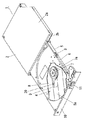
図7は従来の光ディスク装置の外観斜視図である。図7において、1は光ディスク装置、2は筐体、2aは上部筐体部、2bは下部筐体部、3はトレイ、4は光ピックアップモジュール、5はレール、6はレール保持部、7はスピンドルモータ、7aは光ディスク装着部、8は金属製カバー、8aは開口、9はキャリッジ、10はベゼル、11はイジェクトボタン、20は光ピックアップである。 FIG. 7 is an external perspective view of a conventional optical disc apparatus. In FIG. 7, 1 is an optical disk device, 2 is a housing, 2a is an upper housing portion, 2b is a lower housing portion, 3 is a tray, 4 is an optical pickup module, 5 is a rail, 6 is a rail holding portion, and 7 is a A spindle motor, 7a is an optical disk mounting portion, 8 is a metal cover, 8a is an opening, 9 is a carriage, 10 is a bezel, 11 is an eject button, and 20 is an optical pickup.
図7は従来の光ディスク装置の外観斜視図であり、光ディスク装置1は、筐体2と、筐体2に出没自在に保持されたトレイ3を有している。筐体2は、金属製の上部筐体部2a、下部筐体部2bを組み合わせて袋状であり、筐体2の開口からトレイ3が出没する構成となっている。トレイ3には、裏面から光ピックアップモジュール4が取り付けられている。トレイ3の両側部には移動自在にレール5が設けられ、このレール5は、トレイ3に一体に設けられたレール保持部6に保持されている。なお、図7では、一方の側部にのみレール5が設けられているが、他方の側面部に同様のレールが設けられていてもよい。上部筐体部2aと下部筐体部2bとは図示していない係止手段と螺旋などを用いて、互いに強固に固定されている。
FIG. 7 is an external perspective view of a conventional optical disk apparatus. The
光ピックアップモジュール4は、光ディスクを回転駆動させるスピンドルモータ7と、スピンドルモータ7から外周にかけて開口8aを設けた金属製カバー8と、開口8aから一部が露出したキャリッジ9を少なくとも有している。キャリッジ9は、光ピックアップモジュール4に設けられた複数の案内シャフトに移動自在に保持されており、しかも図示していないフィードモータによって、スピンドルモータ7に近づいたり、離れたりするように移動できる。
The
10はトレイ3の前面に設けられたベゼルで、ベゼル10は筐体2の開口を塞ぐ程度の大きさで構成されている。キャリッジ9には、高出力のレーザーダイオード等の光源,各種光学部材及び光ディスク上に光スポットを構成する対物レンズなどが搭載されている。筐体2の奥部には固定して設けられた回路基板があり、回路基板には信号処理系のICや電源回路などが搭載されている。トレイ3に設けられた図示していない回路基板同士を電気的に接続するフレキシブルなプリント基板は、略U字型に形成され、外部コネクタはコンピュータ等の電子機器に設けられた電源/信号ラインと接続される。そして、この外部コネクタを介して光ディスク装置1内に電力を供給したり、あるいは外部からの信号を光ディスク装置内に導いたり、あるいは光ディスク装置1で生成された電気信号を電子機器などに送出する。トレイ3の前端面に設けられたベゼル10にはイジェクトボタン11が設けられており、このイジェクトボタン11を押すことで、筐体2に設けられた係合部と
トレイ3に設けられた係合部との係合を解除し、トレイ3は筐体2から光ディスクが着脱できるよう引き出すことができる。
図8は、従来の光ディスク装置におけるイジェクトロック機構部を示す平面図であり、図7に示す光ディスク装置1のイジェクトボタン11の裏面方向に配置されている。12はソレノイド、13は可動片、14はリセットアーム、15はリリースアーム、16はロックアーム、17はイジェクトスプリング、18はロックシャフト、19はイジェクトアームである。図8はロックアーム16がロックシャフト18に係止した状態を示しており、このとき、トレイ3は閉じた状態となっている。また、イジェクトボタン11を押すことにより可動片13とソレノイド12の吸着が解除されると、リリースアーム15が回動し、リリースアーム15はロックアーム16との接触部を介してロックアーム16を回動させ、これによりロックアーム16がロックシャフト18から離れるとロックが解除されて、トレイ3が開いた状態となる。
FIG. 8 is a plan view showing an eject lock mechanism portion in the conventional optical disc apparatus, which is arranged in the back surface direction of the
このソレノイド12は、その動作部である可動片13がソレノイド12から離脱する動作の後(非リセット状態)、初期位置(リセット状態)に自己復帰が出来ないため、この可動片13を初期位置(リセット状態)に戻す動作が必要となる。そのため、一般的には、図8に示したリセットアーム14やリリースアーム15の回動を利用して、使用者がトレイ3を筐体2に収納する動作によって、可動片13が初期位置(リセット状態)に戻るように復帰動作させる。
The
以下、イジェクトロック機構の復帰動作について、図9を用いて説明する。 Hereinafter, the return operation of the eject lock mechanism will be described with reference to FIG.
図9は、従来の光ディスク装置におけるトレイが筐体に収納される時のイジェクトロック機構部の復帰動作を示す図であり、図9(a)はソレノイド12の可動片13がリセット状態に復帰を開始する状態を示した図であり、図9(b)はソレノイド12の可動片13がリセット状態に復帰する途中の状態を示した図、図9(c)はソレノイド12の可動片13がリセット状態になった状態を示した図である。図9において、12はソレノイド、13は可動片、14はリセットアーム、15はリリースアーム、16はロックアーム、17はイジェクトスプリング、18はロックシャフト、19はイジェクトアームである。
FIG. 9 is a diagram showing the return operation of the eject lock mechanism when the tray in the conventional optical disc apparatus is housed in the housing, and FIG. 9A shows that the
図9(a)に示すように、使用者によりベゼル10を介してトレイ3が筐体2に収納されるとき、ロックシャフト18がリセットアーム14に接触し、リセットアーム14は回動する。次に、図9(b)に示すように、リセットアーム14の回転運動はリリースアーム15へ伝達され、リリースアーム15は可動片13をソレノイド12の方へ近づけ接触させ、可動片13はソレノイド12と吸着する。ここで、可動片13とソレノイド12が吸着した状態が図9(c)である。
As shown in FIG. 9A, when the tray 3 is housed in the
図9(a)〜図9(c)において、トレイ3を筐体2に収納する動作を行う場合、トレイ3と筐体2とにクリアランスが1mm程度あるために、リセットアーム14の回転中心とロックシャフト18の中心間距離、すなわちA寸法がトレイ3の収納条件によって所定の寸法から大きくなったり小さくなったりする。
9A to 9C, when the operation of storing the tray 3 in the
A寸法が最も大きくなった条件、すなわちリセットアーム14がロックシャフト18から最も離れる条件でトレイを収納する場合は、リセットアーム14の回転角度が少なくなり、可動片13の可動距離が最も小さくなる。また、A寸法が最も小さくなった条件、すなわちリセットアーム14がロックシャフト18から最も近づく条件でトレイを収納する場合は、リセットアーム14の回転角度が大きくなり、可動片13の可動距離が最も大きくなる。
When the tray is stored under the condition that the dimension A is the largest, that is, the condition where the
そのため、一般的には、最悪状態でもロックアーム16とロックシャフト18が係合するように可動片13の可動距離が最も小さい場合を基準に可動片13とソレノイド12の位置関係の設計を行なう。
Therefore, generally, the positional relationship between the
先行例としては、(特許文献1)等がある。
しかしながら、上記従来の構成では、図9におけるA寸法が最も小さくなった場合、つまり可動片13の可動距離が最も大きくなった場合、可動片13とソレノイド12の吸着後における可動片13のオーバーストロークも大きくなる。
However, in the conventional configuration, when the dimension A in FIG. 9 is the smallest, that is, when the movable distance of the
そのため、このオーバーストロークで発生する可動片13によるソレノイド12に対する過大な圧着負荷やリリースアーム15、リセットアーム14にかかる荷重負荷により、イジェクトロック機構の寿命を短くしている。
For this reason, the life of the eject lock mechanism is shortened by an excessive crimping load applied to the
本発明は、このような従来の課題を解決するものであり、トレイと筐体を係合するイジェクトロック機構のソレノイドやリリースアームやリセットアームにかかる負荷を低減することができ、イジェクトロック機構の寿命に対する信頼性を高めた光ディスク装置を提供することを目的とする。 The present invention solves such a conventional problem, and can reduce the load applied to the solenoid, release arm, and reset arm of the eject lock mechanism that engages the tray and the casing. An object of the present invention is to provide an optical disc apparatus having improved reliability for life.
本発明は、上記課題を解決するためになされたものであって、筐体に収納されるトレイと、トレイに設けられ、トレイを筐体に収納する際に筐体の内部に設けられたロックシャフトに係合してトレイを筐体に収納された状態に保持するロックアームと、トレイに設けられ、トレイを筐体から引き出す際にロックシャフトとロックアームとの嵌合を解除するソレノイドと、トレイに設けられ、トレイを筐体内に収納する際にロックシャフトに押されて回動するリセットアームと、トレイに設けられ、トレイを筐体内に収納する際にリセットアームの動作に連動して回動する第1のリリースアームと、第1のリリースアームの回動軸と上下方向に重なって連結する回動軸を有し、第1のリリースアームの回動に連動してソレノイドの可動片を押圧する第2のリリースアームと、コイル部分が第1のリリースアームと第2のリリースアームとの連結部に配置され、一方のアーム部は第1のリリースアームに取付けられ、他方のアーム部は第2のリリースアームに取付けられたリリースアームスプリングと、を具備し、トレイを筐体内に収納する際、一方のアーム部と他方のアーム部とがコイル部分を中心に開こうとする力により第1のリリースアームと第2のリリースアームとを連動させ、第2のリリースアームが可動片をソレノイド内の所定の位置まで押圧すると、第2のリリースアームの移動が停止し、一方のアーム部のみが移動自在となり、第1のリリースアームと第2のリリースアームとの連動が解除され、第1のリリースアームのみ独立して回動し、第1のリリースアームの可動片側に位置する端部と第2のリリースアームの可動片側に位置する端部とは、可動片を挟み込むように上下に重なり合い、第1のリリースアームの可動片と反対側に位置する端部と第2のリリースアームの可動片と反対側に位置する端部とは、双方が連動して移動するとき、同一平面上に重なり合って移動することを特徴とする光ディスク装置である。 The present invention has been made to solve the above-described problem, and includes a tray housed in the housing and a lock provided in the tray when the tray is housed in the housing. A lock arm that engages the shaft and holds the tray in a state of being housed in the housing; a solenoid that is provided on the tray and that releases the fitting between the lock shaft and the lock arm when the tray is pulled out of the housing; A reset arm that is provided in the tray and is rotated by being pushed by the lock shaft when the tray is stored in the housing, and is provided in the tray and rotates in conjunction with the operation of the reset arm when the tray is stored in the housing. A first release arm that moves, and a pivot shaft that is connected to the pivot shaft of the first release arm so as to overlap in the vertical direction. The movable piece of the solenoid is moved in conjunction with the pivot of the first release arm. Pressing The second release arm and the coil portion are arranged at the connecting portion between the first release arm and the second release arm, one arm portion is attached to the first release arm, and the other arm portion is the first arm. A release arm spring attached to the two release arms, and when the tray is housed in the housing, the first arm portion and the other arm portion are opened by the force to open around the coil portion. When the release arm and the second release arm are interlocked and the second release arm presses the movable piece to a predetermined position in the solenoid, the movement of the second release arm stops. movement becomes free, the interlock between the first release arm and a second release arm is released, only the first release arm independently rotated, allowed the first release arm The end located on one side and the end located on the movable piece side of the second release arm overlap vertically so as to sandwich the movable piece, and the end located on the opposite side to the movable piece of the first release arm The end portion located on the opposite side of the movable piece of the second release arm is an optical disk device characterized in that when both move together, they move overlapping each other on the same plane .
本発明は上記構成により、トレイを筐体内に収納する際、一方のアーム部と他方のアーム部とがコイル部分を中心に開こうとする力により第1のリリースアームと第2のリリースアームとを連動させ、第2のリリースアームが可動片をソレノイド内の所定の位置まで押圧すると、第2のリリースアームの移動が停止し、一方のアーム部のみが移動自在となり、第1のリリースアームと第2のリリースアームとの連動が解除され、第1のリリースアームのみ独立して回動することにより、可動片の位置に応じて、第1のリリースアームと第2のリリースアームとを同時に回動させる場合と、第1のリリースアームのみ回動させる場合と、に使い分けるので、可動片が所定の位置に達したにもかかわらず、更なる移動を強制するオーバーストロークが発生した場合、ソレノイドやリリースアームやリセットアームにかかる負荷を第1のリリースアームのみ回動させることで吸収することができる。 According to the present invention, when the tray is housed in the housing, the first release arm and the second release arm are caused by the force that one arm portion and the other arm portion try to open around the coil portion. When the second release arm presses the movable piece to a predetermined position in the solenoid, the movement of the second release arm stops, and only one of the arm portions becomes movable, The interlock with the second release arm is released, and only the first release arm rotates independently, so that the first release arm and the second release arm rotate simultaneously according to the position of the movable piece. Since it is used separately for the case where it is moved and the case where only the first release arm is rotated, an over straw that forces further movement even though the movable piece has reached a predetermined position Is generated, the can be absorbed by rotating the load on the solenoid and release arm and a reset arm only the first release arm.
その結果、ソレノイドやリリースアームやリセットアームにかかる負荷を第1のリリースアームのみ回動させることで吸収するので、イジェクトロック機構の寿命に対する信頼性を高めた光ディスク装置を実現することができる。 As a result, since the load applied to the solenoid, the release arm, and the reset arm is absorbed by rotating only the first release arm, it is possible to realize an optical disc apparatus with improved reliability with respect to the life of the eject lock mechanism.
請求項1記載の発明は、筐体に収納されるトレイと、トレイに設けられ、トレイを筐体に収納する際に筐体の内部に設けられたロックシャフトに係合してトレイを筐体に収納された状態に保持するロックアームと、トレイに設けられ、トレイを筐体から引き出す際にロックシャフトとロックアームとの嵌合を解除するソレノイドと、トレイに設けられ、トレイを筐体内に収納する際にロックシャフトに押されて回動するリセットアームと、トレイに設けられ、トレイを筐体内に収納する際にリセットアームの動作に連動して回動する第1のリリースアームと、第1のリリースアームの回動軸と上下方向に重なって連結する回動軸を有し、第1のリリースアームの回動に連動してソレノイドの可動片を押圧する第2のリリースアームと、コイル部分が第1のリリースアームと第2のリリースアームとの連結部に配置され、一方のアーム部は第1のリリースアームに取付けられ、他方のアーム部は第2のリリースアームに取付けられたリリースアームスプリングと、を具備し、トレイを筐体内に収納する際、一方のアーム部と他方のアーム部とがコイル部分を中心に開こうとする力により第1のリリースアームと第2のリリースアームとを連動させ、第2のリリースアームが可動片をソレノイド内の所定の位置まで押圧すると、第2のリリースアームの移動が停止し、一方のアーム部のみが移動自在となり、第1のリリースアームと第2のリリースアームとの連動が解除され、第1のリリースアームのみ独立して回動し、第1のリリースアームの可動片側に位置する端部と第2のリリースアームの可動片側に位置する端部とは、可動片を挟み込むように上下に重なり合い、第1のリリースアームの可動片と反対側に位置する端部と第2のリリースアームの可動片と反対側に位置する端部とは、双方が連動して移動するとき、同一平面上に重なり合って移動することを特徴とするものである。トレイを筐体内に収納する際、一方のアーム部と他方のアーム部とがコイル部分を中心に開こうとする力により第1のリリースアームと第2のリリースアームとを連動させ、第2のリリースアームが可動片をソレノイド内の所定の位置まで押圧すると、第2のリリースアームの移動が停止し、一方のアーム部のみが移動自在となり、第1のリリースアームと第2のリリースアームとの連動が解除され、第1のリリースアームのみ独立して回動することにより、可動片の位置に応じて、第1のリリースアームと第2のリリースアームとを同時に回動させる場合と、第1のリリースアームのみ回動させる場合と、に使い分けるので、可動片が所定の位置に達したにもかかわらず、更なる移動を強制するオーバーストロークが発生した場合、ソレノイドやリリースアームやリセットアームにかかる負荷を第1のリリースアームのみ回動させることで吸収することができる。 According to the first aspect of the present invention, there is provided a tray housed in the housing, and the tray is disposed in the tray by engaging with a lock shaft provided in the housing when the tray is housed in the housing. A lock arm that is held in the tray, a solenoid that is provided on the tray and that releases the fitting between the lock shaft and the lock arm when the tray is pulled out of the housing, and the tray is provided in the tray. A reset arm that is rotated by being pushed by the lock shaft when stored; a first release arm that is provided on the tray and rotates in conjunction with the operation of the reset arm when storing the tray in the housing; A second release arm that has a rotary shaft that is connected to the rotary shaft of the first release arm so as to overlap in the vertical direction, and that presses the movable piece of the solenoid in conjunction with the rotation of the first release arm; The release portion is arranged at the connecting portion between the first release arm and the second release arm, one arm portion is attached to the first release arm, and the other arm portion is attached to the second release arm. An arm spring, and when the tray is stored in the housing, the first release arm and the second release arm are caused by a force that the one arm portion and the other arm portion open about the coil portion. When the second release arm presses the movable piece to a predetermined position in the solenoid, the movement of the second release arm stops and only one of the arm parts becomes movable, and the first release arm When the interlock is released and the second release arm, only the first release arm independently rotated, end and a second Lilly located movable side of the first release arm The end located on the movable piece side of the arm overlaps vertically so as to sandwich the movable piece, and the end located on the opposite side of the movable piece of the first release arm and the opposite side of the movable piece of the second release arm The end portion located at is characterized in that when both move together, they move overlapping each other on the same plane . When the tray is stored in the housing, the first release arm and the second release arm are interlocked with each other by the force that the one arm portion and the other arm portion try to open around the coil portion, When the release arm presses the movable piece to a predetermined position in the solenoid, the movement of the second release arm stops, and only one of the arm parts becomes movable, and the first release arm and the second release arm When the interlock is released and only the first release arm is independently rotated, the first release arm and the second release arm are simultaneously rotated according to the position of the movable piece, and the first Since only the release arm is rotated, it is used separately, so if an overstroke that forces further movement occurs even though the movable piece has reached the predetermined position, The load on the soil and the release arm and a reset arm only the first release arm can be absorbed by rotating.
その結果、ソレノイドやリリースアームやリセットアームにかかる負荷を第1のリリースアームのみ回動させることで吸収するので、イジェクトロック機構の寿命に対する信頼性を高めた光ディスク装置を実現することができる。 As a result, since the load applied to the solenoid, the release arm, and the reset arm is absorbed by rotating only the first release arm, it is possible to realize an optical disc apparatus with improved reliability with respect to the life of the eject lock mechanism.
請求項2記載の発明は、第1のリリースアームの主平面部と、第2のリリースアームの主平面部とが、可動片の主平面部に対して略平行方向で対向することを特徴とするものである。第1のリリースアームの主平面部と、第2のリリースアームの主平面部とが、可動片の主平面部に対して略平行方向で対向することにより、第2のリリースアームが可動片を接続したまま回動する際に必要な強度を薄い形状でも確保するので、リリースアームと可動片との接続構成を薄型で実現できる。
The invention according to
(実施の形態1)
以下、本発明の実施の形態1について、図面を参照しながら説明する。
(Embodiment 1)
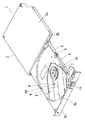
図1は、本発明の実施の形態1における光ディスク装置の外観斜視図である。図1において、1は光ディスク装置、2は筐体、2aは上部筐体部、2bは下部筐体部、3はトレイ、4は光ピックアップモジュール、5はレール、6はレール保持部、7はスピンドルモータ、7aは光ディスク装着部、8は金属製カバー、8aは開口、9はキャリッジ、10はベゼル、11はイジェクトボタン、20は光ピックアップである。
FIG. 1 is an external perspective view of an optical disc apparatus according to
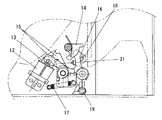
図2は、本発明の実施の形態1におけるイジェクトロック機構部を示す平面図であり、イジェクトロック機構は図1に示す光ディスク装置1のイジェクトボタン11の裏面方向に配置されている。図2において、12はソレノイド、13は可動片、14はリセットアーム、15はリリースアーム、16はロックアーム、17はイジェクトスプリング、18はロックシャフト、21はリリースアームスプリングである。
FIG. 2 is a plan view showing the eject lock mechanism portion according to the first embodiment of the present invention, and the eject lock mechanism is arranged in the rear surface direction of the
図1において、筐体2は上部筐体部2aと下部筐体部2bを組み合わせて袋状に構成されている。上部筐体部2aと下部筐体部2bとは好ましくは螺旋などを用いて、互いに強固に固定されている。筐体2の構成材料としては鉄,鉄合金,アルミニウム,アルミニウム合金、マグネシウム合金等の金属材料や樹脂材料によって構成される。また、上部筐体部2a及び下部筐体部2bはそれぞれ同種の材料で構成しても良いし、異種の材料で構成しても良い。また、上部筐体部2a及び下部筐体部2bそれぞれの主平面部の平均肉厚は0.2mm〜1.6mmの間であり、この平均肉厚の比較的薄い場合には上部筐体部2a及び下部筐体部2bは金属材料で構成され、例えば、金属板をプレス加工などによって形成される。また、平均肉厚の比較的厚い場合には上部筐体部2a及び下部筐体部2bは樹脂材料やダイカスト(アルミニウム合金やマグネシウム合金など)で構成される。筐体2を樹脂材料で構成した場合には、光ディスク装置1の軽量化を実現できる。3は筐体2に出没自在に設けられたトレイで、このトレイ3は樹脂製のフレームで構成され、光ピックアップモジュール4が設けられている。光ピックアップモジュール(PUM)4には光学系を構成した光ピックアップ20と光ディスクを回転させるスピンドルモータ7及び制御回路(図示せず)で構成されている。光ピックアップ20は、光ディスクに光を照射することで、光ディスクに情報を書き込むかあるいは情報を読み出す動作の少なくとも一方を行なう。スピンドルモータ7には光ディスク装着部7aがあり、光ディスクを装着し回転駆動させる。トレイ3の両側部にはレール保持部6があり、両側部共にレール5と光ディスク引き出し方向に摺動自在に嵌合している。また、レール5は筐体2両側部内面に設けられたレールガイドとも光ディスク引き出し方向に摺動自在に嵌合しており、トレイ3は筐体2から光ディスクが着脱できるよう引き出すことが出来る。
In FIG. 1, the
筐体2の奥部には固定して設けられた制御基板があり、制御基板には信号処理系のICや電源回路などが搭載されている。トレイ3に設けられた図示していない制御基板同士を電気的に接続するフレキシブルなプリント基板は、略U字型に形成され、外部コネクタはコンピュータ等の電子機器に設けられた電源/信号ラインと接続される。そして、この外部コネクタを介して光ディスク装置1内に電力を供給したり、或いは外部からの電気信号を光ディスク装置1内に導いたり、あるいは光ディスク装置1で生成された電気信号を電子機器などに送出する。トレイ3の前端面に設けられたベゼル10にはイジェクトボタン11が設けられており、このイジェクトボタン11を押すことで、筐体2に設けられた係合部(図示せず)とトレイ3に設けられた係合部(図示せず)との係合を解除する。
There is a fixed control board at the back of the
トレイ3の前端面に設けられたベゼル10にはイジェクトボタン11が設けられており、このイジェクトボタン11を押すことで、図2に示す筐体2に設けられたイジェクトロック用シャフト18とトレイ3に設けられたロックアーム16との係合を解除する。
The
次に、イジェクトロック機構の詳細について図2を用いて説明する。 Next, details of the eject lock mechanism will be described with reference to FIG.
イジェクトロック機構は、ソレノイド12、可動片13、リリースアーム15、ロックアーム16、イジェクトスプリング17、ロックシャフト18で構成され、可動片13はソレノイド12の中へ挿入されており、リリースアーム15は可動片13とイジェクトスプリング17とに接続しており、リリースアーム15が回動することにより、ロックアーム16を回動させ、ロックシャフト18との係合を解除するものである。
The eject lock mechanism includes a
図2は、ロックアーム16がロックシャフト18に係止した状態を示しており、このときトレイ3は閉じた状態となっている。また、イジェクトボタン11を押すことにより可動片13がイジェクトスプリング17のばね力によりソレノイド12から離脱し、リリースアーム15が回動し、リリースアーム15はロックアーム16との接触部を介してロックアーム16を回動させ、これによりロックアーム16がロックシャフト18から離れる
とロックが解除されて、トレイ3が引き出すことが可能になった状態となる。
FIG. 2 shows a state where the
次に、イジェクトロック機構のソレノイドについて、図3を用いて説明する。 Next, the solenoid of the eject lock mechanism will be described with reference to FIG.
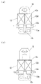
図3は、本発明の実施の形態1におけるイジェクトロック機構のソレノイドの平面図である。図3(a)は、ソレノイド12のリセット状態であり、図1に示すトレイ3が筐体2に収納された状態である。また、図3(b)は、ソレノイド12の非リセット状態であり、図1に示すトレイ3が筐体2から引き出すことが可能になった状態である。図3において、12はソレノイド、12aはヨーク、12bはマグネット、12cはボビン、12dはコイル、12eは端子、13は可動片である。
FIG. 3 is a plan view of the solenoid of the eject lock mechanism according to
ソレノイドはヨーク12a、マグネット12b、ボビン12c、コイル12dで構成され、可動片13、イジェクトスプリング17と共に用いるのが一般的である。リセット状態においては、マグネット12bから発生する磁力によりヨーク12aと可動片13が吸着しており、使用者によりイジェクトボタン11が押されるとイジェクトロック機構の端子12eに電圧がかかり、ボビン12cに巻線されたコイル12dに電流が流れ、マグネット12bから発生する磁力と相反する方向へ磁力が発生し、イジェクトスプリング17の引張り荷重と合成され、可動片13がヨーク12aから離脱し非リセット状態つまりトレイ3が筐体2から引き出し可能な状態に移行する。一度、非リセット状態になるとイジェクトロック機構の端子12eに電圧をかけるのをやめても、マグネット12bから発生する磁力だけでは可動片13をヨーク12aまで引き寄せることができない。そのため、非リセット状態からリセット状態への移行は使用者がトレイ3を筐体2に収納する動作により行なわれる。
The solenoid is composed of a
次に、本発明の特徴部分であるリリースアームについて説明する。 Next, the release arm which is a characteristic part of the present invention will be described.
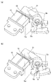
図4は、本発明の実施の形態1におけるリリースアームとソレノイドの接続を示す外観図であり、図4(a)は複数の部材で構成されたリリースアームが一体となって可動している様子を示す図であり、図4(b)は複数の部材で構成されたリリースアームの一部が独立して可動している様子を示す図である。図5は、本発明の実施の形態1におけるリリースアームを示す外観図であり、図5(a)は複数の部材で構成されたリリースアームが一体となって可動している様子を示す図であり、図5(b)は複数の部材で構成されたリリースアームの一部が独立して可動している様子を示す図である。図4、図5において、12はソレノイド、13は可動片、15aは上部リリースアーム、15bは下部リリースアーム、15cは貫通孔、21はリリースアームスプリングである。また、リリースアームが一体となって可動している場合とは、図4、図5に示すB寸法が0の場合をいい、リリースアームの一部が独立して可動している場合とはB寸法が0以外の場合をいう。
FIG. 4 is an external view showing the connection between the release arm and the solenoid according to
リリースアーム15は、可動片13の主平面部と略平行方向に2分割された、上部リリースアーム15aと下部リリースアーム15bで構成され、7mm×18mm程度の大きさで、厚みが約5mmの樹脂などにより形成されている。ここで、略平行とは、可動片13に対して±5°程度のものをいう。
The
上部リリースアーム15aと下部リリースアーム15bは、それぞれ腕部を有し、上部リリースアーム15aには更に可動片13に設けられた貫通孔との接続に必要な突起が設けられている。設けられる突起は、上部リリースアーム15aに限定されるものでは無く、下部リリースアーム15bでも良いのであるが、その場合、リリースアーム15の上下構成を逆にする必要がある。
The
リリースアーム15には、上部リリースアーム15aの貫通孔と下部リリースアーム1
5bの貫通孔で形成された貫通孔15cが設けられ、その貫通孔15cの中にトレイ3に設けられたリリースアーム15の取り付け軸(突起)が挿入され、リリースアーム15の可動は、上部リリースアーム15a、下部リリースアーム15b共に、リリースアーム15に設けられた貫通孔15cの径方向の中心を回転軸にして回転する。また、上部リリースアーム15aと下部リリースアーム15bは、それぞれが一体で回転したり、下部リリースアーム15bのみが回転自在となるように、上部リリースアーム15aと下部リリースアーム15bはリリースアームスプリング21と接続されている。
The
A through-
リリースアームスプリング21は、上部リリースアーム15aと下部リリースアーム15bの間に一定の回転負荷がかかると、下部リリースアーム15bのみが可動するように、上部リリースアーム15aと下部リリースアーム15bに接続されている。
The
以下、本発明の実施の形態1におけるイジェクトロック機構の復帰動作について、図6を用いて説明する。
Hereinafter, the return operation of the eject lock mechanism according to
図6は、本発明の実施の形態1におけるトレイが筐体に収納される時のイジェクトロック機構部の復帰動作を示す図であり、図6(a)はソレノイド12の可動片13がリセット状態に復帰を開始する状態を示した図であり、図6(b)はソレノイド12の可動片13がリセット状態に復帰する途中の状態を示した図、図6(c)はソレノイド12の可動片13がリセット状態になった状態を示した図である。図6において、12はソレノイド、13は可動片、14はリセットアーム、15aは上部リリースアーム、15bは下部リリースアーム、16はロックアーム、17はイジェクトスプリング、18はロックシャフト、19はイジェクトアーム、21はリリースアームスプリングである。
FIG. 6 is a diagram illustrating the return operation of the eject lock mechanism when the tray is housed in the housing according to the first embodiment of the present invention. FIG. 6 (a) is a state where the
図6(a)に示すように、使用者によりベゼル10を介してトレイ3が筐体2に収納されるとき、ロックシャフト18がリセットアーム14に接触し、リセットアーム14は回動する。次に、図6(b)に示すように、リセットアーム14の回転運動はリリースアーム15へ伝達され、リリースアーム15は可動片13をソレノイド12の方へ近づけ接触させ、可動片13はソレノイド12と吸着する。ここで、可動片13とソレノイド12が吸着した状態が図6(c)である。
As shown in FIG. 6A, when the tray 3 is housed in the
図6(a)〜図6(c)において、トレイ3を筐体2に収納する動作を行う場合、トレイ3と筐体2とにクリアランスが1mm程度あるために、リセットアーム14の回転中心とロックシャフト18の中心間距離、すなわちA寸法がトレイ3の収納条件によって所定の寸法から大きくなったり小さくなったりする。
6A to 6C, when the operation of storing the tray 3 in the
従来の光ディスク装置では、図9(a)〜図9(c)に示すA寸法が最も大きくなった条件、すなわちリセットアーム14がロックシャフト18から最も離れる条件でトレイを収納する場合は、リセットアーム14の回転角度が少なくなり、可動片13の可動距離が最も小さくなる。また、A寸法が最も小さくなった条件、すなわちリセットアーム14がロックシャフト18から最も近づく条件でトレイを収納する場合は、リセットアーム14の回転角度が大きくなり、可動片13の可動距離が最も大きくなる。そのため、この場合においては、可動片13とソレノイド12の吸着後における可動片13のオーバーストロークも大きくなり、このオーバーストロークで発生する可動片13によるソレノイド12に対する過大な圧着負荷やリリースアーム15、リセットアーム14にかかる荷重負荷により、イジェクトロック機構の寿命を短くしている。
In the conventional optical disc apparatus, when the tray is stored under the condition that the dimension A shown in FIGS. 9A to 9C is maximized, that is, the condition where the
ところが、図4〜図6に示す本発明の実施の形態1では、可動片13に力を伝達するリリースアーム15が複数の部材により構成され、複数の部材の少なくとも一部である上部リリースアーム15aと下部リリースアーム15bがリリースアームスプリング21と接
続していることにより、一定以上の力が加わらない限り、上部リリースアーム15aと下部リリースアーム15bは共に可動するため、以下の動作となる。
However, in the first embodiment of the present invention shown in FIGS. 4 to 6, the
まず、リセットアーム14からの回転運動を下部リリースアーム15bが受け止める。下部リリースアーム15bは、上部リリースアーム15aと共に可動し、可動片13をソレノイド12の方へ近づけ接触させる。これは、上部リリースアーム15aと下部リリースアーム15bが接続しているリリースアームスプリング21は、可動片13が可動する範囲内においては、一定以上の力とならないためである。
First, the
可動片13がソレノイド12と接触し吸着した後は、可動片13の可動が止まる。このとき、図6(a)〜図6(c)に示すA寸法が最も小さくなった条件、すなわちリセットアーム14がロックシャフト18から最も近づく条件でトレイ3を収納する場合は、リセットアーム14の回転角度が大きくなり、可動片13の可動距離が最も大きくなり、可動片13がソレノイド12と接触し吸着した後にも可動片13はソレノイド12に対して過大な圧着負荷を与えるような場合には、上部リリースアーム15aのみが可動し、過大な圧着負荷を吸収する。トレイ3が収納され、過大な圧着負荷の発生が止まった場合には、リリースアームスプリング21の復元力により、上部リリースアーム15aと下部リリースアーム15bが一体となり元の状態になる。
After the
このようにして、可動片13とソレノイド12の吸着後にも継続して発生する過大な圧着負荷を上部リリースアーム15aと下部リリースアーム15bの独立した可動によって、吸収することが可能となる。
In this way, it is possible to absorb the excessive crimping load continuously generated after the
そのため、トレイと筐体を係合するイジェクトロック機構のソレノイドやリリースアームやリセットアームにかかる負荷を低減することができ、イジェクトロック機構の寿命に対する信頼性を高めた光ディスク装置を実現することができる。 Therefore, the load applied to the solenoid, release arm, and reset arm of the eject lock mechanism that engages the tray and the housing can be reduced, and an optical disc apparatus with improved reliability with respect to the life of the eject lock mechanism can be realized. .
なお、本実施の形態では、リリースアーム15が可動片13の主平面部と略平行方向で2分割されていることとしたが、略平行方向で2分割されていることに限定されるものでは無い。リリースアーム15と可動片13との接続構成を薄型で実現しようと思えば、リリースアーム15が可動片13の主平面部と略平行方向で2分割されていることが好ましい。
In the present embodiment, the
また、リリースアーム15の可動は、上部リリースアーム15a、下部リリースアーム15b共に、リリースアーム15に設けられた貫通孔15cの径方向の中心を回転軸にして回転することとしたが、リリースアーム15に設けられた貫通孔15cの径方向の中心を回転軸にして回転することに限定されるものでない。リリースアーム15のそれぞれの部材がトレイ3との取り付け部に対して、それぞれ独立して一時的に可動することを容易にすることや可動片のオーバーストロークによるソレノイド12に対する過大な圧着負荷やリリースアーム15やリセットアーム14にかかる負荷を効率良く吸収することや最小のスペースで本発明の構成を実現しようと思えば、リリースアーム15の可動は、上部リリースアーム15a、下部リリースアーム15b共に、リリースアーム15に設けられた貫通孔15cの径方向の中心を回転軸にして回転することが好ましい。
The
本発明は、トレイと筐体を係合するイジェクトロック機構のソレノイドやリリースアームやリセットアームにかかる負荷を低減することができ、イジェクトロック機構の寿命に対する信頼性を高めた光ディスク装置を実現することができ、光ピックアップにより光ディスクに対して情報の記録又は再生の少なくとも一方を行なう光ディスク装置などに適応可能である。 The present invention realizes an optical disc apparatus that can reduce a load applied to a solenoid, a release arm, and a reset arm of an eject lock mechanism that engages a tray and a casing, and has improved reliability with respect to the life of the eject lock mechanism. The present invention can be applied to an optical disc apparatus that records and / or reproduces information on / from an optical disc by an optical pickup.
1 光ディスク装置
2 筐体
2a 上部筐体部
2b 下部筐体部
3 トレイ
4 光ピックアップモジュール
5 レール
6 レール保持部
7 スピンドルモータ
7a 光ディスク装着部
8 金属製カバー
8a 開口
9 キャリッジ
10 ベゼル
11 イジェクトボタン
12 ソレノイド
13 可動片
14 リセットアーム
15 リリースアーム
15a 上部リリースアーム
15b 下部リリースアーム
16 ロックアーム
17 イジェクトスプリング
18 ロックシャフト
19 イジェクトアーム
20 光ピックアップ
21 リリースアームスプリング
DESCRIPTION OF
Claims (2)
前記トレイに設けられ、前記トレイを前記筐体に収納する際に前記筐体の内部に設けられたロックシャフトに係合して前記トレイを前記筐体に収納された状態に保持するロックアームと、
前記トレイに設けられ、前記トレイを前記筐体から引き出す際に前記ロックシャフトと前記ロックアームとの嵌合を解除するソレノイドと、
前記トレイに設けられ、前記トレイを前記筐体内に収納する際に前記ロックシャフトに押されて回動するリセットアームと、
前記トレイに設けられ、前記トレイを前記筐体内に収納する際に前記リセットアームの動作に連動して回動する第1のリリースアームと、
前記第1のリリースアームの回動軸と上下方向に重なって連結する回動軸を有し、前記第1のリリースアームの回動に連動して前記ソレノイドの可動片を押圧する第2のリリースアームと、
コイル部分が前記第1のリリースアームと前記第2のリリースアームとの連結部に配置され、一方のアーム部は前記第1のリリースアームに取付けられ、他方のアーム部は前記第2のリリースアームに取付けられたリリースアームスプリングと、を具備し、
前記トレイを前記筐体内に収納する際、一方のアーム部と他方のアーム部とがコイル部分を中心に開こうとする力により第1のリリースアームと第2のリリースアームとを連動させ、
前記第2のリリースアームが前記可動片を前記ソレノイド内の所定の位置まで押圧すると、前記第2のリリースアームの移動が停止し、前記一方のアーム部のみが移動自在となり、前記第1のリリースアームと前記第2のリリースアームとの連動が解除され、前記第1のリリースアームのみ独立して回動し、
前記第1のリリースアームの前記可動片側に位置する端部と前記第2のリリースアームの前記可動片側に位置する端部とは、前記可動片を挟み込むように上下に重なり合い、
前記第1のリリースアームの前記可動片と反対側に位置する端部と前記第2のリリースアームの前記可動片と反対側に位置する端部とは、双方が連動して移動するとき、同一平面上に重なり合って移動することを特徴とする光ディスク装置。 A tray stored in a housing;
A lock arm which is provided on the tray and engages with a lock shaft provided inside the casing when the tray is stored in the casing to hold the tray in a state stored in the casing; ,
A solenoid that is provided on the tray and releases the fitting between the lock shaft and the lock arm when the tray is pulled out of the housing;
A reset arm provided on the tray and rotated by being pushed by the lock shaft when the tray is housed in the housing;
A first release arm provided on the tray and rotating in conjunction with the operation of the reset arm when the tray is stored in the housing;
A second release that has a turning shaft that overlaps and connects with the turning shaft of the first release arm and presses the movable piece of the solenoid in conjunction with the turning of the first release arm; Arm,
A coil portion is disposed at a connecting portion between the first release arm and the second release arm, one arm portion is attached to the first release arm, and the other arm portion is the second release arm. A release arm spring attached to the
When the tray is stored in the housing, the first release arm and the second release arm are interlocked with each other by the force with which one arm portion and the other arm portion try to open around the coil portion,
When the second release arm presses the movable piece to a predetermined position in the solenoid, the movement of the second release arm stops, and only the one arm portion becomes movable, and the first release The linkage between the arm and the second release arm is released, and only the first release arm rotates independently ,
An end portion of the first release arm located on the movable piece side and an end portion of the second release arm located on the movable piece side overlap vertically so as to sandwich the movable piece,
The end portion of the first release arm located on the opposite side of the movable piece and the end portion of the second release arm located on the opposite side of the movable piece are the same when both move together. An optical disc apparatus characterized by moving in an overlapping manner on a plane .
Priority Applications (1)
| Application Number | Priority Date | Filing Date | Title |
|---|---|---|---|
| JP2004304119A JP4462002B2 (en) | 2004-10-19 | 2004-10-19 | Optical disk device |
Applications Claiming Priority (1)
| Application Number | Priority Date | Filing Date | Title |
|---|---|---|---|
| JP2004304119A JP4462002B2 (en) | 2004-10-19 | 2004-10-19 | Optical disk device |
Publications (3)
| Publication Number | Publication Date |
|---|---|
| JP2006120190A JP2006120190A (en) | 2006-05-11 |
| JP2006120190A5 JP2006120190A5 (en) | 2007-08-02 |
| JP4462002B2 true JP4462002B2 (en) | 2010-05-12 |
Family
ID=36537946
Family Applications (1)
| Application Number | Title | Priority Date | Filing Date |
|---|---|---|---|
| JP2004304119A Expired - Fee Related JP4462002B2 (en) | 2004-10-19 | 2004-10-19 | Optical disk device |
Country Status (1)
| Country | Link |
|---|---|
| JP (1) | JP4462002B2 (en) |
Families Citing this family (2)
| Publication number | Priority date | Publication date | Assignee | Title |
|---|---|---|---|---|
| JP4298734B2 (en) | 2006-09-28 | 2009-07-22 | 株式会社日立エルジーデータストレージ | Optical disk device |
| JP2010244660A (en) * | 2009-04-09 | 2010-10-28 | Hitachi-Lg Data Storage Inc | Optical disk device |
-
2004
- 2004-10-19 JP JP2004304119A patent/JP4462002B2/en not_active Expired - Fee Related
Also Published As
| Publication number | Publication date |
|---|---|
| JP2006120190A (en) | 2006-05-11 |
Similar Documents
| Publication | Publication Date | Title |
|---|---|---|
| US6693868B2 (en) | Disc drive having feed chassis supporting members | |
| JP4462002B2 (en) | Optical disk device | |
| US7493635B2 (en) | Recording medium drive device, electronic equipment having the recording medium drive device, and recording medium cartridge | |
| JP4042742B2 (en) | RECORDING MEDIUM DRIVE DEVICE AND ELECTRONIC DEVICE HAVING THE SAME | |
| JP2006085799A (en) | Optical disk device | |
| JP2006085800A (en) | Optical disk device | |
| JP4645683B2 (en) | Disk unit | |
| JPH1139760A (en) | Disk unit | |
| JP4154827B2 (en) | Disk unit | |
| JP4556909B2 (en) | RECORDING MEDIUM DRIVE DEVICE AND ELECTRONIC DEVICE | |
| JP2007066371A (en) | Information playback device | |
| JP2008217923A (en) | Disk unit | |
| JP2007048417A (en) | Optical disk device | |
| JP4300481B2 (en) | Disk drive device and electronic device equipped with the same | |
| JP4200447B2 (en) | RECORDING MEDIUM DRIVE DEVICE AND ELECTRONIC DEVICE | |
| JPH1139759A (en) | Disk unit | |
| JP2006134371A (en) | Disk unit | |
| JPH1139763A (en) | Disk unit | |
| JPH1139809A (en) | Disk unit | |
| JP2007073387A (en) | Electronics | |
| JPH1139770A (en) | Disk unit | |
| JP2001222847A (en) | Disk unit | |
| JP2001222881A (en) | Cable fixing structure for disk unit | |
| JP2005267830A (en) | RECORDING MEDIUM DRIVE DEVICE AND ELECTRONIC DEVICE HAVING THE SAME | |
| JP2001093215A (en) | Cartridge holding mechanism |
Legal Events
| Date | Code | Title | Description |
|---|---|---|---|
| A521 | Written amendment |
Free format text: JAPANESE INTERMEDIATE CODE: A523 Effective date: 20070614 |
|
| A621 | Written request for application examination |
Free format text: JAPANESE INTERMEDIATE CODE: A621 Effective date: 20070614 |
|
| RD01 | Notification of change of attorney |
Free format text: JAPANESE INTERMEDIATE CODE: A7421 Effective date: 20070712 |
|
| A977 | Report on retrieval |
Free format text: JAPANESE INTERMEDIATE CODE: A971007 Effective date: 20091112 |
|
| A131 | Notification of reasons for refusal |
Free format text: JAPANESE INTERMEDIATE CODE: A131 Effective date: 20091117 |
|
| RD01 | Notification of change of attorney |
Free format text: JAPANESE INTERMEDIATE CODE: A7421 Effective date: 20091120 |
|
| A521 | Written amendment |
Free format text: JAPANESE INTERMEDIATE CODE: A523 Effective date: 20091225 |
|
| TRDD | Decision of grant or rejection written | ||
| A01 | Written decision to grant a patent or to grant a registration (utility model) |
Free format text: JAPANESE INTERMEDIATE CODE: A01 Effective date: 20100126 |
|
| A01 | Written decision to grant a patent or to grant a registration (utility model) |
Free format text: JAPANESE INTERMEDIATE CODE: A01 |
|
| A61 | First payment of annual fees (during grant procedure) |
Free format text: JAPANESE INTERMEDIATE CODE: A61 Effective date: 20100208 |
|
| FPAY | Renewal fee payment (event date is renewal date of database) |
Free format text: PAYMENT UNTIL: 20130226 Year of fee payment: 3 |
|
| LAPS | Cancellation because of no payment of annual fees |