JP4460181B2 - Imaging system and imaging apparatus used therefor - Google Patents
Imaging system and imaging apparatus used therefor Download PDFInfo
- Publication number
- JP4460181B2 JP4460181B2 JP2001066191A JP2001066191A JP4460181B2 JP 4460181 B2 JP4460181 B2 JP 4460181B2 JP 2001066191 A JP2001066191 A JP 2001066191A JP 2001066191 A JP2001066191 A JP 2001066191A JP 4460181 B2 JP4460181 B2 JP 4460181B2
- Authority
- JP
- Japan
- Prior art keywords
- imaging
- trigger signal
- input
- output
- terminal
- Prior art date
- Legal status (The legal status is an assumption and is not a legal conclusion. Google has not performed a legal analysis and makes no representation as to the accuracy of the status listed.)
- Expired - Fee Related
Links
Images

Description
【0001】
【発明の属する技術分野】
本発明は、移動物体を複数の撮像装置で撮像する撮像システムおよびそれに用いる撮像装置に関する。
【0002】
【従来の技術】
図2は、従来の撮像システムの例を示す図である。この図2は、ベルトコンベア1上に、缶2a,缶2b,缶2cが間をおいて乗せられていて、ベルトコンベア1により、矢印方向に移動する場合に、この缶2a,2b,2cの各々の缶の複数箇所、例えば、ラベルとかバーコードを撮影することにより、所定個所に、それらが正しく貼り付けられていたり表示されているかを検査する撮像システムである。
【0003】
この缶2a,缶2b,缶2cが在る位置に対応して、撮像装置4a,4b,4cが配置されているが、各々の撮像装置4a,4b,4cは、缶2a,2b,2cの異なる部位を撮影するように設定されている。
【0004】
各々の撮像装置4a,4b,4cは、各々、撮像手段5a,5b,5cと、トリガー信号入力端子6a,6b,6cと、シリアルバス規格IEEE1394に準拠したパソコン信号入出力端子7aおよび8a,シリアルバス規格IEEE1394に準拠したパソコン信号入出力端子7bおよび8b,シリアルバス規格IEEE1394に準拠したパソコン信号入出力端子7cおよび8cを備えている。
【0005】
撮像手段5a,5b,5cは、各々、トリガー信号入力端子5a,5b,5cから入力されるトリガー信号により缶2a,2b,2cの異なる部位を撮影する。撮像手段5a,5b,5cの撮像出力は、パソコン信号入出力端子7a,7b,7cに接続されている。また、パソコン信号入出力端子7a,7b,7cは、パソコン信号入出力端子8a,8b,8cに接続されている。
【0006】
その他に、センサ3a,3bと、トリガー発生器9と、パソコン10が用意されている。
【0007】
センサ3a,3bは、缶2aが移動して通過したときを検出して、タイミングパルスを発生し、トリガー発生器9に送る。トリガー発生器9はこのタイミングパルスに基づき、撮影用トリガー信号を発生する。
【0008】
従来、この撮影用トリガー信号としては、各々の撮像装置4a,4b,4cのトリガー信号入力端子6a,6b,6cに、ケーブル11a,11b,11cを介して、別々に、それら撮像装置毎に応じた撮像用トリガー信号を入力していた。
【0009】
なお、パソコン信号入出力端子7aは、パソコン10との信号のやりとりのため、IEEE1394準拠のケーブル12aに接続され、パソコン信号入出力端子8aはIEEE1394準拠のケーブル12bによりパソコン信号入出力端子7bに接続され、パソコン信号入出力端子8bはIEEE1394準拠のケーブル12cによりパソコン信号入出力端子7cに接続されており、撮像手段で撮像した画像をパソコン10上に表示して検査する。
【0010】
【発明が解決しようとする課題】
以上説明したように、従来は、トリガー発生器9からのトリガー信号を、各々の撮像装置4a,4b,4cのトリガー信号入力端子6a,6b,6cに、ケーブル11a,11b,11cを介して別々に、入力していたので、配線が複雑である。
【0011】
本発明の目的は、トリガー信号の接続を簡素化した撮像システムおよびそれに用いる撮像装置を提供することにある。
【0012】
【課題を解決するための手段】
本発明は、移動物体の移動を検出するセンサと、該検出されたセンサ出力に応じてトリガー信号を発生するトリガー信号発生器と、複数の撮像装置とを有し、前記トリガー信号発生器から出力されたトリガー信号に応じて前記移動物体を前記複数の撮像装置の各撮像装置で撮像する撮像システムにおいて、前記各撮像装置は、トリガー信号を入力する手段と、前記入力したトリガー信号に応じて撮像する撮像手段と、前記入力したトリガー信号を所定の遅延量でもって遅延する手段と、前記遅延したトリガー信号を出力する手段とを有し、前記複数の撮像装置のうち第1の撮像装置の前記トリガー信号入力手段へ前記トリガー信号発生器からのトリガー信号を入力すると共に、前記第1の撮像装置を除く各撮像装置の前記トリガー信号入力手段へそれぞれ他の撮像装置の前記トリガー信号出力手段からそれぞれ遅延したトリガー信号を入力することを特徴とする撮像システムである。
【0013】
本発明は、移動物体を複数の撮像装置で撮像する撮像システムにおいて、前記複数の撮像装置の各々の撮像装置は、撮像手段と、前記撮像手段に撮像用トリガー信号を供給するための入力端子と、出力端子と、前記入力端子に入力された信号を所定時間遅延して前記出力端子に供給する遅延回路を少なくとも備え、前記複数の撮像装置のうちの第1の撮像装置の前記入力端子が、前記移動物体の移動を検出したセンサからのタイミングパルスに応答して発生するトリガー発生器からのトリガー信号を入力する第1線路に接続され、前記第1の撮像装置の前記出力端子が、前記複数の撮像装置のうちの第2の撮像装置の前記入力端子に第2線路で接続されたことを特徴とする撮像システムである。
【0014】
本発明において、前記第2の撮像装置の前記出力端子が、前記複数の撮像装置のうちの第3の撮像装置の前記入力端子に第3線路で接続されたことを特徴とする撮像システムである。
【0015】
本発明において、前記複数の撮像装置の各々の撮像装置は、さらに、入出力第1端子と、前記入出力第1端子からの制御信号により前記遅延回路の遅延時間を制御する手段と、前記入出力第1端子からの制御信号を出力する入出力第2端子を備え、前記複数の撮像装置のうちの第1の撮像装置の前記入出力第1端子が、パソコンからの前記制御信号を入力する第4の線路に接続され、前記第1の撮像装置の前記入出力第2端子が、前記複数の撮像装置のうちの第2の撮像装置の前記入出力第1端子に第5線路で接続されたことを特徴とする撮像システムである。
【0016】
本発明において、前記第2の撮像装置の前記入出力第2端子が、前記複数の撮像装置のうちの第3の撮像装置の前記入出力第1端子に第6線路で接続されたことを特徴とする撮像システムである。
【0017】
本発明において、前記撮像手段の撮像出力が前記入出力第1端子に接続されたことを特徴とする撮像システムである。
【0018】
本発明において、前記入出力第1端子および前記入出力第2端子が、シリアルバス規格IEEE1394に準拠した端子であることを特徴とする撮像システムである。
【0019】
本発明は、撮像手段と、前記撮像手段に撮像用トリガー信号を供給するための入力端子と、出力端子と、前記入力端子に入力された信号を所定時間遅延して前記出力端子に供給する遅延回路を少なくとも備えたことを特徴とする撮像装置である。
【0020】
本発明において、さらに、入出力第1端子と、前記入出力第1端子からの制御信号により前記遅延回路の遅延時間を制御する手段と、前記入出力第1端子からの制御信号を出力する入出力第2端子を備えたことを特徴とする撮像装置である。
【0021】
本発明において、前記撮像手段の撮像出力が前記入出力第1端子に接続されたことを特徴とする撮像装置である。
【0022】
本発明において、前記入力端子および前記出力端子が、シリアルバス規格IEEE1394に準拠した端子であることを特徴とする撮像装置である。
【0023】
【発明の実施の形態】
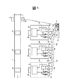
以下、本発明の撮像システムの実施の形態について図1を用いて説明する。図1において、図2と同一個所は同一符号を付してある。各々の撮像装置4a,4b,4cは、各々、さらに、トリガー信号出力端子13a,13b,13cと、トリガー信号入力端子6a,6b,6cおよびトリガー信号出力端子13a,13b,13cの間に接続された遅延回路14a,14b,14cを備えている。この遅延回路14a,14b,14cは、パソコン信号入出力端子7a,7b,7cにも接続されている。
【0024】
そして、トリガー信号入力端子6aはトリガー発生器9からの撮影用トリガー信号を入力するケーブル15aに接続され、トリガー信号出力端子13aはケーブル15bによりトリガー信号入力端子6bに接続され、トリガー信号出力端子13bはケーブル15cによりトリガー信号入力端子6cに接続されている。
【0025】
遅延回路14a,14b,14cの一例としては、プログラマブルカウンタと、D−フリップフロップを備え、プログラマブルカウンタに入力するクロック信号のカウントを、トリガー入力端子6a,6bからのトリガー信号に基づき、缶2a,2b,2c等の移動物体が次段の撮像装置4b,4cの撮影範囲へ移動するまでの時間差だけ遅延させる、具体的には、それぞれ撮像装置の設置位置やベルトコンベアの移動速度等に対応させることで、缶2a,2b,2c等の移動物体を複数の撮像装置で撮像することができる。
【0026】
なお、図において、センサ3a,3bはフォトセンサや赤外センサを図示しているが、これに代えて、別の撮像装置を用意して、缶を検出するようにしてもよい。
【0027】
【発明の効果】
本発明によれば、トリガー信号の接続を簡素化した撮像システムおよびそれに用いる撮像装置を提供することができる。
【図面の簡単な説明】
【図1】本発明の撮像システムの実施の形態を示す図である。
【図2】従来の撮像システムの例を示す図である。
【符号の説明】
1…ベルトコンベア、2a,2b,2c…缶、3a,3b…センサ、4a,4b,4c…撮像装置、5a,5b,5c…撮像手段、6a,6b,6c…トリガー信号入力端子、7a,7b,7c…パソコン信号入出力端子、8a,8b,8c…パソコン信号入出力端子、9…トリガー信号発生器、10…パソコン、11a,11b,11c…ケーブル、12a,12b,12c…ケーブル、13a,13b,13c…トリガー信号出力端子、14a,14b,14c…遅延回路、15a,15b,15c…ケーブル。[0001]
BACKGROUND OF THE INVENTION
The present invention relates to an imaging system for imaging a moving object with a plurality of imaging devices and an imaging device used therefor.
[0002]
[Prior art]
FIG. 2 is a diagram illustrating an example of a conventional imaging system. FIG. 2 shows that the cans 2a, 2b, and 2c are placed on the belt conveyor 1 at intervals, and the cans 2a, 2b, and 2c are moved when the belt conveyor 1 moves in the arrow direction. This is an imaging system that inspects whether or not a plurality of locations of each can, for example, labels or barcodes, are correctly pasted or displayed at predetermined locations.
[0003]
The imaging devices 4a, 4b, and 4c are arranged corresponding to the positions where the cans 2a, 2b, and cans 2c exist. The imaging devices 4a, 4b, and 4c are arranged in the cans 2a, 2b, and 2c. It is set to photograph different parts.
[0004]
Each of the imaging devices 4a, 4b, and 4c includes imaging means 5a, 5b, and 5c, trigger
[0005]
The imaging means 5a, 5b, and 5c respectively image different parts of the cans 2a, 2b, and 2c with trigger signals input from the trigger
[0006]
In addition,
[0007]
The
[0008]
Conventionally, as the trigger signal for photographing, the trigger
[0009]
The personal computer signal input /
[0010]
[Problems to be solved by the invention]
As described above, conventionally, the trigger signal from the trigger generator 9 is separately transmitted to the trigger
[0011]
An object of the present invention is to provide an imaging system in which connection of trigger signals is simplified and an imaging apparatus used therefor.
[0012]
[Means for Solving the Problems]
The present invention includes a sensor that detects movement of a moving object, a trigger signal generator that generates a trigger signal in accordance with the detected sensor output, and a plurality of imaging devices, and outputs from the trigger signal generator In the imaging system in which the moving object is imaged by each imaging device of the plurality of imaging devices according to the triggered signal, each imaging device is configured to input a trigger signal and to image according to the input trigger signal Imaging means, means for delaying the input trigger signal by a predetermined delay amount, means for outputting the delayed trigger signal, and the first imaging device of the first imaging device among the plurality of imaging devices. The trigger signal from the trigger signal generator is input to the trigger signal input means, and the trigger signal input hand of each imaging device except the first imaging device is input. To respectively imaging system characterized by inputting a trigger signal delayed respectively from the trigger signal output means of another imaging device.
[0013]
The present invention provides an imaging system for imaging a moving object with a plurality of imaging devices, wherein each of the imaging devices includes an imaging unit and an input terminal for supplying an imaging trigger signal to the imaging unit. And an output terminal and a delay circuit that delays a signal input to the input terminal for a predetermined time and supplies the output terminal to the output terminal, and the input terminal of the first imaging device among the plurality of imaging devices includes: Connected to a first line that inputs a trigger signal from a trigger generator that is generated in response to a timing pulse from a sensor that detects the movement of the moving object, and the output terminal of the first imaging device includes the plurality of output terminals. It is an imaging system characterized by being connected to the input terminal of the second imaging device among the imaging devices of No. 2 by a second line.
[0014]
In the present invention, the output terminal of the second imaging device is connected to the input terminal of the third imaging device among the plurality of imaging devices by a third line. .
[0015]
In the present invention, each of the plurality of imaging devices further includes an input / output first terminal, means for controlling a delay time of the delay circuit by a control signal from the input / output first terminal, and the input An input / output second terminal for outputting a control signal from the output first terminal is provided, and the input / output first terminal of the first imaging device among the plurality of imaging devices inputs the control signal from a personal computer. Connected to a fourth line, and the input / output second terminal of the first imaging device is connected to the input / output first terminal of the second imaging device of the plurality of imaging devices via a fifth line. An imaging system characterized by the above.
[0016]
In the present invention, the input / output second terminal of the second imaging device is connected to the input / output first terminal of the third imaging device of the plurality of imaging devices by a sixth line. It is an imaging system.
[0017]
In the present invention, an imaging output of the imaging means is connected to the input / output first terminal.
[0018]
In the present invention, the input / output first terminal and the input / output second terminal are terminals compliant with a serial bus standard IEEE1394.
[0019]
The present invention relates to an imaging unit, an input terminal for supplying an imaging trigger signal to the imaging unit, an output terminal, and a delay for supplying a signal input to the input terminal to the output terminal after a predetermined delay. An imaging apparatus including at least a circuit.
[0020]
In the present invention, an input / output first terminal, means for controlling a delay time of the delay circuit by a control signal from the input / output first terminal, and an input for outputting a control signal from the input / output first terminal. An imaging apparatus including an output second terminal.
[0021]
In the present invention, the imaging output of the imaging means is connected to the input / output first terminal.
[0022]
In the present invention, the input terminal and the output terminal are terminals compliant with a serial bus standard IEEE1394.
[0023]
DETAILED DESCRIPTION OF THE INVENTION
Hereinafter, an embodiment of an imaging system of the present invention will be described with reference to FIG. 1, the same parts as those in FIG. 2 are denoted by the same reference numerals. Each imaging device 4a, 4b, 4c is further connected between trigger
[0024]
The trigger
[0025]
The
[0026]
In the figure, the
[0027]
【The invention's effect】
ADVANTAGE OF THE INVENTION According to this invention, the imaging system which simplified the connection of the trigger signal, and the imaging device used therefor can be provided.
[Brief description of the drawings]
FIG. 1 is a diagram showing an embodiment of an imaging system of the present invention.
FIG. 2 is a diagram illustrating an example of a conventional imaging system.
[Explanation of symbols]
DESCRIPTION OF SYMBOLS 1 ... Belt conveyor, 2a, 2b, 2c ... Can, 3a, 3b ... Sensor, 4a, 4b, 4c ... Imaging device, 5a, 5b, 5c ... Imaging means, 6a, 6b, 6c ... Trigger signal input terminal, 7a, 7b, 7c ... PC signal input / output terminals, 8a, 8b, 8c ... PC signal input / output terminals, 9 ... Trigger signal generator, 10 ... PC, 11a, 11b, 11c ... Cable, 12a, 12b, 12c ... Cable, 13a , 13b, 13c ... trigger signal output terminals, 14a, 14b, 14c ... delay circuits, 15a, 15b, 15c ... cables.
Claims (4)
撮像手段と、前記撮像手段に撮像用トリガー信号を供給するための入力端子と、出力端子と、前記入力端子に入力された信号を、前記移動物体が次段の撮像装置の撮影範囲へ移動するまでの時間差だけ遅延させて前記出力端子に供給する遅延回路を少なくとも備えたことを特徴とする撮像装置。 In an imaging device for use in an imaging system that images a moving object with a plurality of imaging devices,
The moving object moves the imaging unit, an input terminal for supplying an imaging trigger signal to the imaging unit, an output terminal, and a signal input to the input terminal to the imaging range of the imaging device at the next stage. An image pickup apparatus comprising at least a delay circuit that is delayed by a time difference up to and supplied to the output terminal.
Priority Applications (1)
| Application Number | Priority Date | Filing Date | Title |
|---|---|---|---|
| JP2001066191A JP4460181B2 (en) | 2001-03-09 | 2001-03-09 | Imaging system and imaging apparatus used therefor |
Applications Claiming Priority (1)
| Application Number | Priority Date | Filing Date | Title |
|---|---|---|---|
| JP2001066191A JP4460181B2 (en) | 2001-03-09 | 2001-03-09 | Imaging system and imaging apparatus used therefor |
Publications (3)
| Publication Number | Publication Date |
|---|---|
| JP2002271682A JP2002271682A (en) | 2002-09-20 |
| JP2002271682A5 JP2002271682A5 (en) | 2008-04-17 |
| JP4460181B2 true JP4460181B2 (en) | 2010-05-12 |
Family
ID=18924720
Family Applications (1)
| Application Number | Title | Priority Date | Filing Date |
|---|---|---|---|
| JP2001066191A Expired - Fee Related JP4460181B2 (en) | 2001-03-09 | 2001-03-09 | Imaging system and imaging apparatus used therefor |
Country Status (1)
| Country | Link |
|---|---|
| JP (1) | JP4460181B2 (en) |
Families Citing this family (1)
| Publication number | Priority date | Publication date | Assignee | Title |
|---|---|---|---|---|
| JP4700563B2 (en) * | 2005-06-15 | 2011-06-15 | 株式会社日立国際電気 | Data transmission method and data transmission system |
-
2001
- 2001-03-09 JP JP2001066191A patent/JP4460181B2/en not_active Expired - Fee Related
Also Published As
| Publication number | Publication date |
|---|---|
| JP2002271682A (en) | 2002-09-20 |
Similar Documents
| Publication | Publication Date | Title |
|---|---|---|
| JP2006203448A (en) | On-vehicle stereoscopic camera device | |
| CN107705282B (en) | Information processing system, information processing apparatus, position specifying method, and recording medium | |
| JP6245886B2 (en) | Image capturing method and image capturing apparatus | |
| EP1339227A3 (en) | Image pickup apparatus | |
| EP1246447A3 (en) | Image processing system | |
| US6065072A (en) | Device for selectively passing video frames from a signal series having a first frame rate to obtain a signal series having a second frame rate | |
| EP1675063A3 (en) | Image pickup apparatus and control method of the apparatus | |
| CN111371982B (en) | Data synchronization method, processor and vehicle-mounted terminal | |
| JP4460181B2 (en) | Imaging system and imaging apparatus used therefor | |
| JP2016532099A (en) | Synchronize imaging | |
| JPH08223472A (en) | Video signal output method, image processing camera and image processing system using it | |
| JP2018022974A (en) | On-vehicle camera device, on-vehicle camera adjustment device, and on-vehicle camera adjustment system | |
| JP3585166B2 (en) | Image inspection apparatus for camera module and image inspection method for camera module | |
| WO2004029548A1 (en) | Apparatus and method for capturing images from a camera | |
| WO2001068326A2 (en) | Smart camera for controlling an actuator | |
| WO2014013907A1 (en) | Image processing device and method, and program | |
| CN110475075B (en) | Exposure signal feedback system and method and unmanned aerial vehicle | |
| JP2007028588A (en) | Video transmission method and video transmitting system | |
| JP3611912B2 (en) | TV camera equipment | |
| CN111082807B (en) | Analog signal processing method and device | |
| JP3024640B1 (en) | Imaging device | |
| JP2754832B2 (en) | Image processing device | |
| US20080158399A1 (en) | Image sensor module, signal generation device and signal generation method | |
| JPH1155566A (en) | Image pickup device and its method | |
| JP6720721B2 (en) | Image data acquisition system |
Legal Events
| Date | Code | Title | Description |
|---|---|---|---|
| A521 | Request for written amendment filed |
Free format text: JAPANESE INTERMEDIATE CODE: A523 Effective date: 20080227 |
|
| A621 | Written request for application examination |
Free format text: JAPANESE INTERMEDIATE CODE: A621 Effective date: 20080227 |
|
| A131 | Notification of reasons for refusal |
Free format text: JAPANESE INTERMEDIATE CODE: A131 Effective date: 20091104 |
|
| A521 | Request for written amendment filed |
Free format text: JAPANESE INTERMEDIATE CODE: A523 Effective date: 20091224 |
|
| RD02 | Notification of acceptance of power of attorney |
Free format text: JAPANESE INTERMEDIATE CODE: A7422 Effective date: 20091224 |
|
| TRDD | Decision of grant or rejection written | ||
| A01 | Written decision to grant a patent or to grant a registration (utility model) |
Free format text: JAPANESE INTERMEDIATE CODE: A01 Effective date: 20100202 |
|
| A01 | Written decision to grant a patent or to grant a registration (utility model) |
Free format text: JAPANESE INTERMEDIATE CODE: A01 |
|
| A61 | First payment of annual fees (during grant procedure) |
Free format text: JAPANESE INTERMEDIATE CODE: A61 Effective date: 20100212 |
|
| R150 | Certificate of patent or registration of utility model |
Ref document number: 4460181 Country of ref document: JP Free format text: JAPANESE INTERMEDIATE CODE: R150 Free format text: JAPANESE INTERMEDIATE CODE: R150 |
|
| FPAY | Renewal fee payment (event date is renewal date of database) |
Free format text: PAYMENT UNTIL: 20130219 Year of fee payment: 3 |
|
| FPAY | Renewal fee payment (event date is renewal date of database) |
Free format text: PAYMENT UNTIL: 20130219 Year of fee payment: 3 |
|
| FPAY | Renewal fee payment (event date is renewal date of database) |
Free format text: PAYMENT UNTIL: 20140219 Year of fee payment: 4 |
|
| R250 | Receipt of annual fees |
Free format text: JAPANESE INTERMEDIATE CODE: R250 |
|
| LAPS | Cancellation because of no payment of annual fees |