JP4459397B2 - Method for manufacturing flexible tube for endoscope - Google Patents
Method for manufacturing flexible tube for endoscope Download PDFInfo
- Publication number
- JP4459397B2 JP4459397B2 JP2000207361A JP2000207361A JP4459397B2 JP 4459397 B2 JP4459397 B2 JP 4459397B2 JP 2000207361 A JP2000207361 A JP 2000207361A JP 2000207361 A JP2000207361 A JP 2000207361A JP 4459397 B2 JP4459397 B2 JP 4459397B2
- Authority
- JP
- Japan
- Prior art keywords
- outer skin
- tube
- flexible tube
- core
- core material
- Prior art date
- Legal status (The legal status is an assumption and is not a legal conclusion. Google has not performed a legal analysis and makes no representation as to the accuracy of the status listed.)
- Expired - Fee Related
Links
- 238000000034 method Methods 0.000 title claims description 49
- 238000004519 manufacturing process Methods 0.000 title claims description 37
- 239000011162 core material Substances 0.000 claims description 128
- 239000000463 material Substances 0.000 claims description 58
- 238000005219 brazing Methods 0.000 claims description 21
- 238000010438 heat treatment Methods 0.000 claims description 15
- 238000001125 extrusion Methods 0.000 claims description 12
- YCKRFDGAMUMZLT-UHFFFAOYSA-N Fluorine atom Chemical compound [F] YCKRFDGAMUMZLT-UHFFFAOYSA-N 0.000 claims description 11
- 229910052731 fluorine Inorganic materials 0.000 claims description 11
- 239000011737 fluorine Substances 0.000 claims description 11
- 229920001971 elastomer Polymers 0.000 claims description 9
- 239000005060 rubber Substances 0.000 claims description 9
- 239000011248 coating agent Substances 0.000 claims description 7
- 238000000576 coating method Methods 0.000 claims description 7
- 229920005989 resin Polymers 0.000 claims description 6
- 239000011347 resin Substances 0.000 claims description 6
- 229920002379 silicone rubber Polymers 0.000 claims description 6
- 239000004945 silicone rubber Substances 0.000 claims description 6
- 238000004804 winding Methods 0.000 claims description 6
- 239000000853 adhesive Substances 0.000 claims description 4
- 230000001070 adhesive effect Effects 0.000 claims description 3
- 238000009954 braiding Methods 0.000 claims description 3
- 239000002184 metal Substances 0.000 description 18
- 229910052751 metal Inorganic materials 0.000 description 18
- 238000003780 insertion Methods 0.000 description 17
- 230000037431 insertion Effects 0.000 description 17
- 238000005452 bending Methods 0.000 description 8
- 230000002093 peripheral effect Effects 0.000 description 8
- 230000000694 effects Effects 0.000 description 7
- 239000000835 fiber Substances 0.000 description 7
- 238000005476 soldering Methods 0.000 description 6
- 239000004820 Pressure-sensitive adhesive Substances 0.000 description 5
- 238000004073 vulcanization Methods 0.000 description 5
- 229910000679 solder Inorganic materials 0.000 description 4
- 238000004659 sterilization and disinfection Methods 0.000 description 4
- 238000003466 welding Methods 0.000 description 4
- 230000008602 contraction Effects 0.000 description 3
- 210000002445 nipple Anatomy 0.000 description 3
- 239000013307 optical fiber Substances 0.000 description 3
- 230000001954 sterilising effect Effects 0.000 description 3
- 239000000645 desinfectant Substances 0.000 description 2
- 230000004927 fusion Effects 0.000 description 2
- 230000000149 penetrating effect Effects 0.000 description 2
- 239000010935 stainless steel Substances 0.000 description 2
- 229910001220 stainless steel Inorganic materials 0.000 description 2
- 239000000126 substance Substances 0.000 description 2
- 208000035473 Communicable disease Diseases 0.000 description 1
- RYGMFSIKBFXOCR-UHFFFAOYSA-N Copper Chemical compound [Cu] RYGMFSIKBFXOCR-UHFFFAOYSA-N 0.000 description 1
- 229910000881 Cu alloy Inorganic materials 0.000 description 1
- JOYRKODLDBILNP-UHFFFAOYSA-N Ethyl urethane Chemical compound CCOC(N)=O JOYRKODLDBILNP-UHFFFAOYSA-N 0.000 description 1
- 229920000181 Ethylene propylene rubber Polymers 0.000 description 1
- NIXOWILDQLNWCW-UHFFFAOYSA-N acrylic acid group Chemical group C(C=C)(=O)O NIXOWILDQLNWCW-UHFFFAOYSA-N 0.000 description 1
- 229920000180 alkyd Polymers 0.000 description 1
- 125000000217 alkyl group Chemical group 0.000 description 1
- 229910045601 alloy Inorganic materials 0.000 description 1
- 239000000956 alloy Substances 0.000 description 1
- 239000003795 chemical substances by application Substances 0.000 description 1
- 239000012141 concentrate Substances 0.000 description 1
- 239000000470 constituent Substances 0.000 description 1
- 229910052802 copper Inorganic materials 0.000 description 1
- 239000010949 copper Substances 0.000 description 1
- 238000010586 diagram Methods 0.000 description 1
- 238000013213 extrapolation Methods 0.000 description 1
- 229920001973 fluoroelastomer Polymers 0.000 description 1
- 238000005286 illumination Methods 0.000 description 1
- 230000001771 impaired effect Effects 0.000 description 1
- 239000000314 lubricant Substances 0.000 description 1
- 238000002844 melting Methods 0.000 description 1
- 230000008018 melting Effects 0.000 description 1
- 229920000052 poly(p-xylylene) Polymers 0.000 description 1
- 229920000728 polyester Polymers 0.000 description 1
- 229920001296 polysiloxane Polymers 0.000 description 1
- 238000010008 shearing Methods 0.000 description 1
- 229920002050 silicone resin Polymers 0.000 description 1
- 229920003051 synthetic elastomer Polymers 0.000 description 1
- 229920003002 synthetic resin Polymers 0.000 description 1
- 239000000057 synthetic resin Substances 0.000 description 1
- 239000005061 synthetic rubber Substances 0.000 description 1
- XLYOFNOQVPJJNP-UHFFFAOYSA-N water Substances O XLYOFNOQVPJJNP-UHFFFAOYSA-N 0.000 description 1
Images


Landscapes
- Endoscopes (AREA)
- Rigid Pipes And Flexible Pipes (AREA)
Description
【0001】
【発明の属する技術分野】
本発明は、内視鏡用可撓管の製造方法に関するものである。
【0002】
【従来の技術】
内視鏡の挿入部や光源との接続部に用いられる内視鏡用可撓管は、螺旋管の外周を網状管(編組体)で被覆した管状の芯材に、合成樹脂や合成ゴム等で構成された外皮が被覆された構成となっている。
【0003】
このような内視鏡用可撓管は、従来、次のように製造されていた。まず、螺旋管の外周に網状管を被覆する。次に、その状態で、螺旋管と網状管とをその両端付近で半田付け(ろう接)して固定する。その後、押出成形等の方法によって、さらに外皮を被覆する。
【0004】
ここで、医療用内視鏡は、感染症等を予防するため、使用する都度、消毒・滅菌を行う必要がある。この消毒・滅菌を行う方法に、従来の消毒液等の使用に代わるものとして、オートクレーブ(高圧蒸気滅菌)がある。このオートクレーブでは、内視鏡は、例えば、135℃、2気圧程度の高温高圧の水蒸気に5〜20分程度さらされる。
【0005】
したがって、内視鏡をオートクレーブによって滅菌をすることができるものとするためには、内視鏡用可撓管もオートクレーブ時の高温に対する耐熱性が求められる。このため、内視鏡用可撓管の外皮の材料としては、例えばフッ素ゴムやシリコーンゴム等の耐熱性に優れた材料を使用する必要がある。
【0006】
フッ素ゴムやシリコーンゴム等を外皮材料とした場合には、外皮を内視鏡用可撓管の芯材に被覆した後、外皮材料に対して熱処理(加硫)を施す必要がある。このような熱処理(加硫)の際の温度は、例えば、250〜300℃程度である。
【0007】
しかし、外皮を熱処理する際のこのような温度は、多くの半田(軟ろう)の融点よりも高いため、次のような問題があった。それは、外皮を熱処理するために内視鏡用可撓管を加熱すると、螺旋管と網状管とを固定していた半田が溶融し、螺旋管と網状管との固定が損なわれるという問題である。
【0008】
このため、従来、外皮の熱処理を行う場合には、螺旋管と網状管との固定に溶接(融接)等の他の方法を用いる必要があった。このため、製造効率の低下、製造コストの増大を招いていた。
【0009】
また、熱処理後に、螺旋管と網状管との半田付け(ろう接)を行うこともできるが、この場合、半田付けに先立ち、芯材の両端付近に密着した外皮を除去する必要がある。しかし、外皮の一部は、網状管の網目等に入り込んでいるため、芯材に密着した外皮を完全に除去するのは困難であった。また、芯材に密着した外皮の除去が不十分な状態で半田付け(ろう接)を行うと、残存した外皮材料によって、螺旋管と網状管との密着性が十分に得られない場合があった。したがって、このような方法で内視鏡用可撓管を製造した場合、製造効率の低下、製造コストの増大、螺旋管と網状管との密着性の低下等の問題を招いていた。
【0010】
【発明が解決しようとする課題】
本発明の目的は、比較的簡単な製造工程で、螺旋管と編組体と外皮との密着性(結合力)に優れた内視鏡用可撓管を得ることができる内視鏡用可撓管の製造方法を提供することにある。
【0011】
【課題を解決するための手段】
このような目的は、下記(1)〜(9)の本発明により達成される。
【0012】
(1) 帯状材を螺旋状に巻回して形成された螺旋管に芯金を挿通し、前記螺旋管の外径が自然状態における外径より小さくなるように前記螺旋管を前記芯金に仮止めした状態で、前記螺旋管の外周に、細線を編組して形成された編組体を被覆して芯材を作製する工程と、
前記芯材の端部付近の外周に、剥離部材を被覆する工程と、
前記剥離部材で被覆された前記芯材に外皮を被覆する工程と、
前記仮止めを解除して、前記外皮で被覆された前記芯材から、前記芯金を抜き取る工程と、
前記芯材の端部付近における前記外皮を前記剥離部材とともに除去する工程と、
前記外皮の除去により前記芯材が露出した部分において、前記螺旋管と前記編組体とをその端部付近でろう接する工程とを有することを特徴とする内視鏡用可撓管の製造方法。
【0013】
これにより、比較的簡単な製造工程で、螺旋管と編組体と外皮との密着性(結合力)に優れた内視鏡用可撓管を製造することができる。
【0014】
(2) 前記ろう接工程の前に、前記編組体に被覆した外皮に対して熱処理を施す工程を有する上記(1)に記載の内視鏡用可撓管の製造方法。
【0015】
これにより、熱処理を必要とする外皮材料を利用して内視鏡用可撓管を製造することができる。
【0016】
(3) 前記熱処理は、前記外皮の材料を加硫するものである上記(2)に記載の内視鏡用可撓管の製造方法。
【0017】
これにより、加硫を必要とする外皮材料を利用して内視鏡用可撓管を製造することができる。
【0018】
(4) 前記外皮の材料は、フッ素ゴムおよびシリコーンゴムの少なくとも一方を含むものである上記(1)ないし(3)のいずれかに記載の内視鏡用可撓管の製造方法。
これにより、耐熱性に優れた内視鏡用可撓管を製造することができる。
【0021】
(5) 前記剥離部材は、少なくとも片方の面付近がフッ素系樹脂を含む材料で構成されたものである上記(1)ないし(4)のいずれかに記載の内視鏡用可撓管の製造方法。
【0022】
これにより、熱処理を必要とする外皮材料を用いた場合においても、生産性良く内視鏡用可撓管を製造することができる。
【0023】
(6) 前記剥離部材は、帯状のテープである上記(1)ないし(5)のいずれかに記載の内視鏡用可撓管の製造方法。
これにより、生産性良く内視鏡用可撓管を製造することができる。
【0028】
(7) 前記外皮を被覆する工程は、前記芯材を長手方向に移動しながら、前記外皮の材料を押し出し口から押し出して、押し出した前記外皮の材料を、その一部を前記芯材の隙間に浸透させつつ、前記芯材の外周に被覆するものである上記(1)ないし(6)のいずれかに記載の内視鏡用可撓管の製造方法。
【0029】
これにより、芯材と外皮との密着性がさらに優れた内視鏡用可撓管を生産性良く製造することができる。
【0030】
(8) 前記芯材の端部付近における前記外皮は、前記外皮の少なくとも外表面に切れ目を入れることにより、前記剥離部材とともに除去されるものである上記(1)ないし(7)のいずれかに記載の内視鏡用可撓管の製造方法。
これにより、生産性良く内視鏡用可撓管を製造することができる。
(9) 前記剥離部材は、その表面付近の少なくとも一部が粘着剤を含む材料で構成されたものである上記(1)ないし(8)のいずれかに記載の内視鏡用可撓管の製造方法。
これにより、芯材の端部付近における剥離部材の固定をさらに確実なものとすることができる。その結果、外皮を被覆する工程において、剥離部材が芯材の端部付近からずれるのを防止することができ、芯材の端部付近の編組体、螺旋管が外皮と密着するのをより確実に防止することができる。
【0031】
【発明の実施の形態】
以下、本発明の内視鏡用可撓管の製造方法の好適な実施形態について、添付図面を参照しつつ説明する。
【0032】
まず、本発明の方法により製造される内視鏡用可撓管を有する内視鏡の全体構成の一例について説明する。
【0033】
図1は、本発明の方法により製造される内視鏡用可撓管を有するファイバー内視鏡(ファイバースコープ)を示す全体図である。以下、図1中の上側を「基端」、下側を「先端」として説明する。
【0034】
図1に示すファイバー内視鏡1は、可撓性(弾力性)を有する挿入部可撓管11と、挿入部可撓管11の先端部に設けられた湾曲管12と、挿入部可撓管11の基端部に設けられ、術者が把持してファイバー内視鏡1全体を操作する操作部13と、操作部13の基端部に設けられ、被写体の像を直接観察する接眼部14と、操作部13に接続されたライトガイド可撓管15と、ライトガイド可撓管15の先端側に設けられた光源差込部16とで構成されている。
【0035】
本発明の内視鏡用可撓管の製造方法は、挿入部可撓管11やライトガイド可撓管15の製造に使用することができるものである。
【0036】
挿入部可撓管11は、生体の管腔内に挿入して使用される。また、操作部13には、操作レバー17が設置されている。この操作レバー17を操作すると、挿入部可撓管11内に配設されたワイヤー(図示せず)が牽引されて、湾曲管12が2方向に湾曲し、その湾曲方向を変えることができる。
【0037】
光源差込部16の先端部には、光源用コネクタ18が設置され、この光源用コネクタ18が光源装置(図示せず)に接続されている。光源装置から発せられた光は、光源用コネクタ18、および、光源差込部16内、ライトガイド可撓管15内、操作部13内、挿入部可撓管11内および湾曲管12内に連続して配設された光ファイバー束によるライトガイド(図示せず)を通り、湾曲管12の先端部より観察部位に照射され、照明する。
【0038】
前記照明光により照明された観察部位からの反射光(被写体像)は、挿入部可撓管11内および操作部13内に連続して配設された光ファイバー束によるイメージガイド(図示せず)を通り、接眼部14へ伝達される。
【0039】
接眼部14の内部には、接眼レンズ(図示せず)が設置され、イメージガイド内を通って到達した反射光がこの接眼レンズを通して観察される。
【0040】
以上、ファイバー内視鏡1の全体構成について説明したが、本発明の内視鏡用可撓管の製造方法は、ファイバー内視鏡に限らず、電子内視鏡の内視鏡用可撓管の製造にも使用することができることは、言うまでもない。
【0041】
次に、本発明の内視鏡用可撓管の製造方法を図2〜図13に示す好適実施形態に基づいて詳細に説明する。
【0042】
本発明の内視鏡用可撓管の製造方法は、次のような各工程を有する。
[1]芯材3を作製する工程
まず、芯材3を作製する。
【0043】
図2は、芯材の部分縦断面図である。
図2に示すように、芯材3は、螺旋管31と、網状管32(編組体)とで構成されている。螺旋管31は、帯状材を均一な径で螺旋状に間隔を開けて巻回して形成されたものである。帯状材を構成する材料としては、例えば、ステンレス鋼、銅系合金等が好ましく用いられる。また、網状管32は、金属製または非金属製の細線321を複数並べたものを編組して形成されたものである。細線321を構成する材料としては、例えば、ステンレス鋼、銅系合金等が好ましく用いられる。
【0044】
芯材3は、螺旋管31の外周に網状管32(編組体)を被覆することにより作製される。
【0045】
螺旋管31の外周への網状管32(編組体)の被覆は、いかなる方法で行われてもよいが、螺旋管31を芯金8に巻回した状態で行われるのが好ましい。これにより、螺旋管31の形状が安定し、網状管32(編組体)の被覆を容易に行うことができる。また、芯金8に巻回された状態における螺旋管31の外径D' は、自然状態(外力が作用していない状態)における螺旋管31の外径Dより小さくなっているのが好ましい。
【0046】
以下、芯金8を用いた芯材3の作製方法について説明する。
図3は、螺旋管の自然状態を示す正面図、図4は、螺旋管を芯金に仮止めした状態を示す正面図、図5は、螺旋管を芯金に仮止めした状態を示す側面図、図6は、芯金に仮止めした螺旋管の外周に網状管を被覆した状態を示す正面図である。以下の説明では、図3、図4中の左側を「先端」、右側を「基端」として説明する。
【0047】
図3に示すような自然状態(外径D)の螺旋管31を用意する。この螺旋管31の先端部を内周側に折り曲げて、図4および図5に示すように、折り曲げ部311を形成しておく。このような螺旋管31に芯金8を挿通する。芯金8の両端付近には、溝81、82が形成されており、折り曲げ部311を芯金8の先端側の溝81に通して、螺旋管31の先端が芯金8に対して回転しないようにする。そして、螺旋管31の基端を帯状材の巻回方向に捩じっていく。そうすると、螺旋管31は、その外径D' が次第に縮小するように変形する。
【0048】
このようにして、螺旋管31を縮径状態にした後、螺旋管31の基端に先端と同様の折り曲げ部312を形成する。そして、この折り曲げ部312を芯金8の基端側の溝82に通し、螺旋管31が元の形状に復元しないように仮止めする。なお、螺旋管31を芯金に仮止めする方法は、前述したような折り曲げ部311、312と溝81、82とによる方法によらず、いかなる方法でもよい。
【0049】
芯金8に巻回した螺旋管31の外周に、さらに網状管32を被覆することにより、図6に示すような芯金8に巻回された芯材3が得られる。螺旋管31の外周に網状管32を被覆する方法としては、例えば、以下のような方法が挙げられる。
【0050】
筒状の網状管32を用意し、この網状管32内に、芯金8に巻回した螺旋管31を挿通する。その後、芯金8の両端付近で、網状管32を針金6で緊縛することにより、螺旋管31と網状管32とがずれないように固定する。このとき、螺旋管31は、その外周のほぼ全面が網状管32の内周と密着しているのが好ましい。これにより、螺旋管31と網状管32との密着性に優れた内視鏡用可撓管2を得ることができる。
【0051】
螺旋管の外周に網状管を被覆する方法は、前述したような方法に限定されず、例えば、芯金に巻回された螺旋管の外周に、シート状の編組体を巻着するような方法であってもよい。
【0052】
なお、芯金8は、少なくとも網状管32が被覆された後に除去されればよいが、本実施形態では、後述する外皮5の被覆工程の後に除去されるものとして説明する。
【0053】
[2]芯材3の外周に剥離部材4を被覆する工程
図7は、芯材の端部付近を剥離部材で被覆した状態を示す正面図である。
【0054】
次に、前記[1]で作製された芯材3の端部付近の外周に剥離部材4を被覆する。
【0055】
剥離部材4は、芯材3の外周に外皮5を被覆した際に芯材3の端部付近の網状管32、螺旋管31に外皮5が密着するのを防止する機能を有する。これにより、後述する螺旋管31と網状管32とのろう接を簡便かつ確実に行うことができる。
【0056】
この剥離部材4は、少なくとも芯材3と接触する側の面(以下、「芯材接触面」という)付近が芯材3との密着性の低い材料で構成されたものであるのが好ましい。これにより、後述する芯材3の端部付近の外皮5を剥離部材4とともに除去する工程において、芯材3の外周から剥離部材4を容易に除去することが可能となる。それに伴い、外皮5の除去も容易なものとなり、結果として、内視鏡用可撓管2の生産性が向上する。
【0057】
また、剥離部材4は、少なくとも外皮5と接触する側の面(以下、「外皮接触面」という)付近が外皮5との密着性の低い材料で構成されたものであるのが好ましい。これにより、剥離部材4と外皮5との剥離性は、優れたものとなる。そのため、後述する芯材3の端部付近の外皮5を剥離部材4とともに除去する工程において、剥離部材4と外皮5とを容易に剥離することが可能となる。それに伴い、剥離部材4の除去も容易なものとなり、結果として、内視鏡用可撓管2の生産性が向上する。
【0058】
このような外皮5との密着性、芯材3との密着性が低い材料としては、例えば、フッ素系樹脂、シリコーン系樹脂、長鎖アルキル系樹脂、アルキッド系樹脂、等が挙げられるが、その中でも特に、フッ素系樹脂が好ましい。芯材接触面付近、外皮接触面付近の構成材料としてフッ素系樹脂を用いることにより、後述する熱処理を行った場合でも剥離部材4が芯材3、外皮5と密着するのを効果的に防止することができる。その結果、外皮5に対して熱処理を施す必要がある場合であっても、内視鏡用可撓管を生産性良く製造することが可能となる。
【0059】
本実施形態では、剥離部材4として帯状のテープを用いている。剥離部材4としてこのようなテープを用いると、本工程を容易かつ確実に行うことができる。これにより、芯材3の端部付近の網状管32、螺旋管31に外皮5が密着するのをより確実に防止することができる。また、剥離部材4としてこのようなテープを用いた場合、後述する芯材3の端部付近の外皮5を剥離部材4とともに除去する工程において、芯材3の外周から剥離部材4を容易に除去することができる。
【0060】
剥離部材4としてこのようなテープを用いる場合、その表面付近の少なくとも一部が粘着剤を含む材料で構成されたものであるのが好ましい。これにより、芯材3の端部付近における剥離部材4の固定をさらに確実なものとすることができる。その結果、後述する外皮を被覆する工程において、剥離部材4が芯材3の端部付近からずれるのを防止することができ、芯材3の端部付近の網状管32、螺旋管31が外皮5と密着するのをより確実に防止することができる。粘着剤としては、例えば、アクリル系粘着剤、ポリエステル系粘着剤、ウレタン系粘着剤、ゴム系粘着剤等が挙げられる。
【0061】
[3]芯材3の外周に外皮5を被覆する工程
次に、剥離部材4で被覆された芯材3の外周に外皮5を被覆する。
【0062】
このとき、外皮5は、芯材3(網状管32および螺旋管31)の少なくとも一部を埋め込むように被覆されるのが好ましい。これにより、次のような効果が得られる。
【0063】
・外皮5と芯材3との間の結合力が強くなり、外皮5が芯材3から剥離(分離)しにくいものとなる。
・外皮5の耐久性が向上し、亀裂等が生じにくいものとなる。
・芯材3(網状管32および螺旋管31)の材質、網状管32の編組の密度等の選択、埋め込み部分の厚さ等を調整することにより、外皮5の可撓性(弾力性)を所望に調節することができる。
【0064】
外皮5を構成する材料としては、特に限定されないが、芯材3に被覆した後に熱処理(加硫)を必要とするものであるのが好ましく、例えば、フッ素ゴム、シリコーンゴム、エチレンプロピレンゴムよりなる群から選択される少なくとも1種を含むものであるのが好ましい。後述するように、本発明によれば、外皮5に対して熱処理を施す場合であっても、螺旋管31と網状管32とをろう接によって簡便に固定することができるため、熱処理を必要とする外皮材料51を使用した場合に本発明の優位性がより大きいものとなる。
【0065】
特に、外皮5の材料をフッ素ゴムおよびシリコーンゴムの少なくとも一方を含むものとした場合には、外皮5が耐熱性に優れたものとなる。これにより、オートクレーブ(高圧蒸気滅菌)によって滅菌を行うことができる内視鏡用可撓管2を製造することができる。
【0066】
外皮5を芯材3に被覆する方法としては、特に限定されないが、次に説明するような押出成形により容易に被覆することができる。
【0067】
図8は、押出成形により、剥離部材で被覆された芯材に外皮を被覆している押出成形機のダイスヘッドの部分の縦断面図である。以下の説明では、図8中の左側を「先端」、右側を「基端」として説明する。
【0068】
ダイスヘッド7は、ダイス71とニップル72とを有している。ダイスヘッド7には、基端から先端に貫通する円形断面の通路73が形成されている。
【0069】
芯金8に巻回した芯材3を、通路73内に同心的に挿通し、図示しない移送手段により、基端から先端に向かって長手方向(図8中の矢印A方向)に移動する。
【0070】
ダイスヘッド7の内部には、ダイス71とニップル72とによって、外皮材料通路74が形成されている。外皮材料通路74の先端は、通路73内に周状に開口しており、押し出し口75を形成している。
【0071】
外皮材料通路74には、ホッパー(図示せず)に投入された外皮材料51が、シリンダ(図示せず)内のスクリュー(図示せず)によって順次送り込まれる(図8中の矢印B部)。送り込まれた外皮材料51は、外皮材料通路74を通って、押し出し口75から押し出され、長手方向に移動する芯材3の外周に順次被覆される。
【0072】
押し出された外皮材料51の一部は、芯材3の隙間33に浸透させる。これにより、外皮5が芯材3から極めて剥離しにくいものとなる。また、芯材3が外皮5に埋め込まれることにより、強度等の性能を維持しつつ、内視鏡用可撓管2の外径を細径化(または、内径を拡大化)することができる。
押出成形を終えた後、芯金8を抜き取る。
【0073】
図9は、外皮で被覆された芯材から芯金を抜き取った状態を示す縦断面図である。図9中、D'' は、芯材3から芯金8を抜き取った状態における螺旋管31の外径を示す。
【0074】
芯金8の抜き取りは、例えば、以下のようにして行うことができる。
針金6および折り曲げ部311、312が除去されるように、芯材3の両端付近を切断する。折り曲げ部311、312を除去することにより、螺旋管31は、芯金8に対する固定から解除される。これにより、螺旋管31は、縮径状態(外径D' )から元の外径(自然状態)に復元しようとして、網状管32および外皮5に対して、外周方向に押し広げるような力を及ぼし続ける。このため、螺旋管31の外径は、幾分拡大し(D'' <D' )、それに伴い、螺旋管31の内径も拡大する。その結果、螺旋管31と芯金8との間に隙間が生じ、芯金8を芯材3から容易に抜き取ることが可能となる。
【0075】
また、螺旋管31の外径が拡大することにより、螺旋管31と網状管32と外皮5との密着性がさらに向上する。その結果、内視鏡用可撓管を繰り返し使用した場合であっても、螺旋管31と網状管32と外皮5とが、ずれにくいものとなる。
【0076】
このように、螺旋管31の外周面が網状管32および外皮5の内周面に常に押し付けられているため、螺旋管31と網状管32と外皮5との密着性(結合力)が強い。これにより、内視鏡用可撓管2が弾力性に特に優れたものとなる。その理由について、次に説明する。
【0077】
内視鏡用可撓管2を曲げたときに、その曲げた部分では、外皮5は、芯材3の曲がりに沿って外側では伸長し、内側では収縮する。一方、外皮5が芯材3に対して確実に固定されているので、内視鏡用可撓管2の真っ直ぐな部分では、外皮5は伸縮しない。このため、外皮5は、内視鏡用可撓管2の曲がった部分で集中して伸縮するため、その単位長さ当たりの伸縮割合が大きい。したがって、内視鏡用可撓管2の曲がった部分において、外皮5に発生する局部的な復元力が大きいので、曲がった内視鏡用可撓管2の復元が確実になされる。これにより、内視鏡用可撓管2が弾力性に優れたものとなる。
【0078】
これに対し、従来のように外皮5の芯材5に対する固定が不十分であると、外皮5が芯材3に対してずれ易くなる。このような場合には、内視鏡用可撓管2を曲げたとき、外皮5は、その曲げた部分だけでなく、真っ直ぐな部分も含めた全長に渡る部分で伸縮を吸収することとなる。このため、外皮5の単位長さ当たりの伸縮の割合が小さくなって、外皮5に発生する復元力は小さい。このため、曲がった内視鏡用可撓管2の復元が確実になされない。
【0079】
図10は、図9に示す縦断面の一部を拡大して示す縦断面図である。
図10に示すように、螺旋管31を形成する帯状材は、その片面にかえり313(バリ)が形成されている。このかえり313は、板材からせん断加工により帯状材を切り出した際に形成されるものである。螺旋管31は、このような帯状材のかえり313を外周側に向けて巻回して形成したものであるのが好ましい。これにより、かえり313が網状管32および外皮5に対してアンカー効果を生じ、螺旋管31と網状管32との密着性(結合力)、螺旋管31と外皮5との密着性(結合力)は、さらに優れたものとなる。このように、かえり313を外周側に向けることによるアンカー効果は、前述の芯材3を埋め込むように外皮5を被覆することによる効果と相乗的に作用し、その結果、螺旋管31と網状管32と外皮5との固定は、より確実なものとなる。また、螺旋管31の内周面がかえり313のない平滑なものとなるため、内視鏡用可撓管2の内部に挿通される光ファイバー、ケーブル、チューブ類等の内蔵物を傷つけることがない。
【0080】
なお、芯材3の外周に外皮5を被覆する方法は、前述したような押出成形に限定されず、いかなる方法でもよい。また、芯金8を芯材3から抜き取る方法は、前述したような方法に限定されず、いかなる方法でもよい。
【0081】
[4]外皮5に対して熱処理を施す工程
芯材3に外皮5を被覆した後、必要に応じて熱処理を施す。これにより、外皮5の性質を改善して、内視鏡用可撓管に、例えば、耐熱性向上等の効果を与えることができる。熱処理の目的としては、外皮材料51の加硫が挙げられるが、これに限定されない。
【0082】
なお、この熱処理は、後述する芯材3の端部付近の外皮5を除去する工程の後に行われるものであってもよい。
【0083】
[5]芯材3の端部付近の外皮5を除去する工程
図11は、芯材の端部付近の外皮と剥離部材とを除去した後の状態を示す図である。
【0084】
図11に示すように、芯材3の端部付近の外皮5を除去する。この部位の外皮5は、剥離部材4とともに除去される。外皮5の除去は、例えば、剥離部材4を被覆してある部分と被覆していない部分との境界(図9中の矢印で示す部分)上の外皮5のほぼ全周に切れ目を入れる等の方法により行うことができる。また、必要に応じて、除去される部位の外皮5に、長手方向の切れ目を入れてもよい。
【0085】
このとき、外皮5と剥離部材4とは、同時に除去されるものであってもよいし、別々に除去されるものであってもよい。また、外皮5と剥離部材4とが別々に除去される場合、外皮5を除去した後に剥離部材4を除去してもよいし、剥離部材4を除去した後に外皮5を除去してもよい。
【0086】
このとき、剥離部材4の芯材接触面付近が芯材3との密着性の低い材料で構成されていると、芯材3の外周から剥離部材4を容易に除去することができる。そのため、外皮5も容易に除去することができる。
【0087】
また、剥離部材4の外皮接触面付近が外皮5との密着性の低い材料で構成されていると、剥離部材4と外皮5との剥離性は、優れたものとなっている。そのため、剥離部材4と外皮5とを容易に剥離することができる。そのため、剥離部材4も容易に除去することができる。
【0088】
[6]螺旋管31と網状管32とをろう接する工程
前記[5]で外皮5が除去され、芯材3が露出した部分において、螺旋管31と網状管32とをろう接(半田付け)して固定し、内視鏡用可撓管2を得る。このろう接は、芯材2の外側(例えば、図11中の矢印Aで示す部分)に施されるものであってもよいし、芯材2の内側(例えば、図11中の矢印Bで示す部分)に施されるものであってもよい。
【0089】
本発明では、外皮5の熱処理(加硫等)をろう接の前に行うことができるので、熱処理を行った際に、網状管32と螺旋管31とを固定している半田が溶融して、この固定が損なわれるという問題が生じない。これにより、外皮5の熱処理を行う場合にも、網状管32と螺旋管31との固定に溶接(融接)等の他の方法を使用する必要がなく、低コストで簡便なろう接を使用することができる。また、芯材3の端部付近には外皮5が密着していないため、網状管32と螺旋管31とのろう接を簡便かつ確実に行うことができる。
【0090】
このようにして製造された内視鏡用可撓管2は、端部に口金91を装着して、操作部13や光源差込部16に接続される。次に説明するように、口金91を内視鏡用可撓管2の端部に固定するろう接と、網状管32と螺旋管31とのろう接を一度に行っても良い。
【0091】
図12は、内視鏡用可撓管が操作部に接続されている部分の縦断面図である。以下の説明では、図12中の左側を「先端」、右側を「基端」として説明する。
【0092】
図12に示すように、内視鏡用可撓管2は、口金91を介して操作部13に接続されている。
【0093】
口金91の先端部には、筒状をなす外挿部92が形成されている。外挿部92の内径は、芯材3の端部における外径とほぼ同じ大きさになっている。そして、この外挿部92が内視鏡用可撓管2の基端に外挿されている。外挿部92には、ろう接用孔93が形成されている。口金91の外側から、このろう接用孔93が形成されている部分をろう接する。これにより、網状管32と螺旋管31とが固定されるとともに、口金91が内視鏡用可撓管2に固定される。
【0094】
内視鏡用可撓管2と口金91との接続部分の外周には、熱収縮チューブ94を被覆して、水密性を高めることとしても良い。また、内視鏡用可撓管2と口金91との隙間に接着剤(図示せず)を充填することにより、水密性を高めることとしても良い。
【0095】
口金91は、操作部13に固定用ビス95で固定される。また、内視鏡用可撓管2と操作部13との接続部分の全体は、おさえゴム96で覆われている。口金91および操作部13とおさえゴム96との間には、Oリング97が設置され、水密性が確保されている。内視鏡用可撓管2の外周面21には、例えばパリレンのような潤滑剤をコーティングしても良い。
【0096】
図13は、本発明の方法により製造した内視鏡用可撓管の他の一例を示す拡大縦断面図である。
【0097】
図13に示す内視鏡用可撓管2は、外皮5が内層52と外層53との2層の積層体で構成されている。そして、芯材3は、内層52に埋め込まれている。
【0098】
このように、外皮5は、2層または3層以上の積層体であってもよい。このような外皮5の各層は、互いに物理的特性または化学的特性が異なる材料で構成することができる。これにより、外皮5の各層の特性の組み合わせによって、内視鏡用可撓管2に必要とされる各種の性能を同時に優れたものとすることができる。
【0099】
例えば、内層52に芯材3との密着性に優れた材料を使用することにより、外皮5を芯材3により確実に固定することができる。
【0100】
また、内層52に弾力性の優れた材料を使用することにより、内層52が外層53と螺旋管31との間のクッションとして作用し、内視鏡用可撓管2の弾力性をより優れたものとすることができる。
【0101】
また、外層53に耐薬品性に優れた材料を使用することにより、消毒液の使用に対する耐久性に優れたものとすることができる。
【0102】
外皮5は、その全長に渡ってこのような積層体で構成してもよく、長手方向の一部についてこのような積層体で構成してもよい。
【0103】
このような複数の積層体で構成された外皮5を芯材3に被覆する方法は、特に限定されず、例えば、複数の押し出し口75を備えた押出成形機によって複数の層を同時に押し出して、その積層体を芯材3に被覆することができる。
【0104】
以上、本発明の内視鏡用可撓管の製造方法を添付図面に示す好適な実施形態に基づいて説明したが、本発明は、これらに限定されるものではない。
【0105】
例えば、本実施形態では、剥離部材4としてテープを用いているが、剥離部材4は、これに限定されるものではない。例えば、剥離部材4として、フッ素系、シリコーン系等の離型剤を塗布して形成したシート材等を用いてもよい。
【0106】
また、本実施形態では、自然状態における螺旋管31の外径D、縮径状態における螺旋管31の外径D' 、および芯材3から芯金8を抜き取った状態における螺旋管31の外径D'' は、それぞれ、全長に渡ってほぼ一定となっているが、これらの値は、長手方向に沿って変化するものであってもよい。
【0107】
【発明の効果】
以上述べたように、本発明によれば、網状管と螺旋管とのろう接を容易かつ確実に行うことができる。このため、比較的簡単な製造工程で、網状管と螺旋管と外皮との密着性に優れた内視鏡用可撓管を製造することができる。特に、外皮に対して熱処理を施す必要がある場合においても、螺旋管と網状管との固定にろう接を使用することができる。
【0108】
また、芯材の端部付近には、外皮の残存がないので口金等の取り付けも容易に行うことができる。
【0109】
また、螺旋管の外径が自然状態における螺旋管の外径より小さくなった状態で、螺旋管の外周に網状管を被覆することにより、螺旋管と網状管との密着性(結合力)、螺旋管と外皮との密着性を向上することができる。
【0110】
また、芯材の外周に外皮を被覆する工程を、外皮材料の一部が芯材の隙間に浸透するように行うことにより、螺旋管と編組体と外皮との密着性が向上する。
【0111】
これらの効果を組み合わせることにより、特に優れた弾力性、耐久性を有する内視鏡用可撓管を製造することができる。
【図面の簡単な説明】
【図1】本発明の方法により製造される内視鏡用可撓管を有するファイバー内視鏡の一例を示す全体図である。
【図2】芯材の部分縦断面図である。
【図3】螺旋管の自然状態を示す正面図である。
【図4】螺旋管を芯金に仮止めした状態を示す正面図である。
【図5】螺旋管を芯金に仮止めした状態を示す側面図である。
【図6】芯金に仮止めした螺旋管の外周に網状管を被覆した状態を示す正面図である。
【図7】芯材の端部付近を剥離部材で被覆した状態を示す正面図である。
【図8】押出成形により、剥離部材で被覆された芯材に外皮を被覆する工程を示す縦断面図である。
【図9】外皮で被覆された芯材から芯金を抜き取った状態を示す縦断面図である。
【図10】図9に示す縦断面の一部を拡大して示す拡大縦断面図である。
【図11】芯材の端部付近の外皮と剥離部材とを除去した後の状態を示す縦断面図である。
【図12】内視鏡用可撓管と操作部との接続部分を示す縦断面図である。
【図13】本発明の方法により製造した内視鏡用可撓管の拡大縦断面図である。
【符号の説明】
1 ファイバー内視鏡
11 挿入部可撓管
12 湾曲管
13 操作部
14 接眼部
15 ライトガイド可撓管
16 光源差込部
17 操作レバー
18 光源用コネクタ
2 内視鏡用可撓管
21 外周面
3 芯材
31 螺旋管
311 折り曲げ部
312 折り曲げ部
313 かえり
32 網状管
321 細線
33 隙間
4 剥離部材
5 外皮
51 外皮材料
52 内層
53 外層
6 針金
7 ダイスヘッド
71 ダイス
72 ニップル
73 通路
74 外皮材料通路
75 押し出し口
8 芯金
81 溝
82 溝
91 口金
92 外挿部
93 ろう接用孔
94 熱収縮チューブ
95 固定用ビス
96 おさえゴム
97 Oリング[0001]
BACKGROUND OF THE INVENTION
The present invention relates to a method for manufacturing a flexible tube for an endoscope.
[0002]
[Prior art]
Endoscope flexible tubes used for endoscope insertion parts and light source connection parts are made of synthetic resin, synthetic rubber, etc. on a tubular core material in which the outer periphery of a helical tube is covered with a mesh tube (braided body) It is the structure which coat | covered the outer skin comprised by this.
[0003]
Conventionally, such a flexible tube for an endoscope has been manufactured as follows. First, a mesh tube is coated on the outer periphery of the spiral tube. Next, in that state, the spiral tube and the mesh tube are fixed by soldering (brazing) near both ends thereof. Thereafter, the outer skin is further coated by a method such as extrusion.
[0004]
Here, the medical endoscope needs to be sterilized and sterilized every time it is used in order to prevent infectious diseases and the like. Autoclave (high pressure steam sterilization) is an alternative to the conventional use of disinfectant and the like in this method of disinfection / sterilization. In this autoclave, the endoscope is exposed to high-temperature and high-pressure steam at, for example, 135 ° C. and 2 atm for about 5 to 20 minutes.
[0005]
Therefore, in order to enable the endoscope to be sterilized by an autoclave, the endoscope flexible tube is also required to have heat resistance against high temperatures during autoclaving. For this reason, it is necessary to use a material having excellent heat resistance such as fluorine rubber and silicone rubber as the material of the outer skin of the flexible tube for endoscope.
[0006]
When the outer skin material is made of fluorine rubber, silicone rubber, or the like, it is necessary to heat treat (vulcanize) the outer skin material after covering the outer skin with the core material of the endoscope flexible tube. The temperature at the time of such heat treatment (vulcanization) is, for example, about 250 to 300 ° C.
[0007]
However, such a temperature at the time of heat-treating the outer skin is higher than the melting point of many solders (soft solder), and thus has the following problems. That is, when the endoscope flexible tube is heated in order to heat-treat the outer skin, the solder that has fixed the spiral tube and the mesh tube is melted, and the fixation between the spiral tube and the mesh tube is impaired. .
[0008]
For this reason, conventionally, when heat-treating the outer skin, it has been necessary to use another method such as welding (fusion welding) for fixing the spiral tube and the mesh tube. For this reason, the production efficiency is reduced and the production cost is increased.
[0009]
In addition, soldering (brazing) between the helical tube and the mesh tube can be performed after the heat treatment, but in this case, it is necessary to remove the outer skin that is in close contact with both ends of the core material prior to soldering. However, since a part of the outer skin has entered the mesh of the reticulated tube, it has been difficult to completely remove the outer skin that is in close contact with the core material. In addition, if soldering (brazing) is performed with insufficient removal of the outer skin adhered to the core material, sufficient adhesion between the spiral tube and the mesh tube may not be obtained due to the remaining outer skin material. It was. Therefore, when a flexible tube for an endoscope is manufactured by such a method, problems such as a decrease in manufacturing efficiency, an increase in manufacturing cost, and a decrease in adhesion between a spiral tube and a mesh tube have been caused.
[0010]
[Problems to be solved by the invention]
It is an object of the present invention to provide an endoscope flexible tube that can provide an endoscope flexible tube excellent in adhesion (bonding force) between a helical tube, a braided body, and an outer skin by a relatively simple manufacturing process. It is to provide a method for manufacturing a pipe.
[0011]
[Means for Solving the Problems]
Such purposes are as follows (1) to (9This is achieved by the present invention.
[0012]
(1) Spiral tube formed by spirally winding a band-shaped materialThe spiral tube is inserted in a state where the spiral tube is temporarily fixed to the core metal so that the outer diameter of the spiral tube is smaller than the outer diameter in the natural state.A step of producing a core material by coating a braided body formed by braiding fine wires on the outer periphery of
Coating the peeling member on the outer periphery near the end of the core; and
Covering the core material coated with the release member with an outer skin;
Releasing the temporary fixing and extracting the cored bar from the core coated with the outer skin; and
Removing the outer skin near the end of the core together with the peeling member;
A method for manufacturing a flexible tube for an endoscope, comprising: a step of brazing the spiral tube and the braided body in the vicinity of an end portion of the portion where the core material is exposed by removing the outer skin.
[0013]
Thereby, the flexible tube for endoscopes excellent in the adhesiveness (bonding force) between the spiral tube, the braided body, and the outer skin can be manufactured by a relatively simple manufacturing process.
[0014]
(2) The method for manufacturing a flexible tube for an endoscope according to (1), further including a step of performing a heat treatment on the outer skin covered with the braid before the brazing step.
[0015]
Thereby, the flexible tube for endoscopes can be manufactured using the outer skin material which requires heat processing.
[0016]
(3) The method for manufacturing a flexible tube for an endoscope according to (2), wherein the heat treatment vulcanizes the material of the outer skin.
[0017]
Thereby, the flexible tube for endoscopes can be manufactured using the outer skin material which requires vulcanization.
[0018]
(4) The method for manufacturing a flexible tube for an endoscope according to any one of (1) to (3), wherein the material of the outer skin includes at least one of fluorine rubber and silicone rubber.
Thereby, the flexible tube for endoscopes excellent in heat resistance can be manufactured.
[0021]
(5The above-mentioned peeling member is composed of a material containing a fluorine-based resin in at least one of the surfaces (1) to (1)4The manufacturing method of the flexible tube for endoscopes in any one of 2).
[0022]
Thereby, even when an outer skin material that requires heat treatment is used, the endoscope flexible tube can be manufactured with high productivity.
[0023]
(6) The peeling member is a strip-shaped tape.5The manufacturing method of the flexible tube for endoscopes in any one of 2).
Thereby, the flexible tube for endoscopes can be manufactured with high productivity.
[0028]
(7) The step of covering the outer skin is performed by extruding the material of the outer skin from the extrusion port while moving the core material in the longitudinal direction, and penetrating part of the extruded material of the outer skin into the gap of the core material. (1) to (1), which covers the outer periphery of the core material6The manufacturing method of the flexible tube for endoscopes in any one of 2).
[0029]
Thereby, the flexible tube for endoscopes having further excellent adhesion between the core material and the outer skin can be manufactured with high productivity.
[0030]
(8(1) to (1) to (1), wherein the outer skin in the vicinity of the end of the core material is removed together with the peeling member by making a cut in at least the outer surface of the outer skin.7The manufacturing method of the flexible tube for endoscopes in any one of 2).
Thereby, the flexible tube for endoscopes can be manufactured with high productivity.
(9) The flexible tube for an endoscope according to any one of (1) to (8), wherein at least a part of the peeling member is made of a material containing an adhesive. Production method.
Thereby, fixation of the peeling member in the edge part vicinity of a core material can be made still more reliable. As a result, in the step of covering the outer skin, the peeling member can be prevented from being displaced from the vicinity of the end of the core material, and the braided body and the spiral tube in the vicinity of the end of the core material are more reliably in close contact with the outer skin. Can be prevented.
[0031]
DETAILED DESCRIPTION OF THE INVENTION
DESCRIPTION OF EXEMPLARY EMBODIMENTS Hereinafter, a preferred embodiment of a method for producing an endoscope flexible tube according to the invention will be described with reference to the accompanying drawings.
[0032]
First, an example of the entire configuration of an endoscope having an endoscope flexible tube manufactured by the method of the present invention will be described.
[0033]
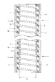
FIG. 1 is an overall view showing a fiber endoscope having a flexible tube for an endoscope manufactured by the method of the present invention. In the following description, the upper side in FIG. 1 is referred to as a “base end”, and the lower side is referred to as a “tip”.
[0034]
A fiber endoscope 1 shown in FIG. 1 includes an insertion portion flexible tube 11 having flexibility (elasticity), a bending
[0035]
The endoscope flexible tube manufacturing method of the present invention can be used for manufacturing the insertion portion flexible tube 11 and the light guide
[0036]
The insertion portion flexible tube 11 is used by being inserted into a lumen of a living body. An
[0037]
A light source connector 18 is installed at the distal end of the light
[0038]
The reflected light (subject image) from the observation site illuminated by the illumination light is sent to an image guide (not shown) by an optical fiber bundle arranged continuously in the insertion portion flexible tube 11 and the
[0039]
An eyepiece lens (not shown) is installed inside the
[0040]
The overall configuration of the fiber endoscope 1 has been described above. However, the endoscope flexible tube manufacturing method according to the present invention is not limited to the fiber endoscope, and the endoscope flexible tube for an electronic endoscope. It goes without saying that it can also be used in the manufacture of
[0041]
Next, the manufacturing method of the flexible tube for endoscopes of this invention is demonstrated in detail based on suitable embodiment shown in FIGS.
[0042]
The method for manufacturing an endoscope flexible tube according to the present invention includes the following steps.
[1] Process for producing
First, the
[0043]
FIG. 2 is a partial longitudinal sectional view of the core material.
As shown in FIG. 2, the
[0044]
The
[0045]
The outer periphery of the
[0046]
Hereinafter, a method for producing the
3 is a front view showing a natural state of the spiral tube, FIG. 4 is a front view showing a state where the spiral tube is temporarily fixed to the cored bar, and FIG. 5 is a side view showing a state where the spiral tube is temporarily fixed to the cored bar. FIG. 6 and FIG. 6 are front views showing a state in which a mesh tube is coated on the outer periphery of a spiral tube temporarily fixed to a core metal. In the following description, the left side in FIGS. 3 and 4 will be described as the “tip” and the right side as the “base end”.
[0047]
A
[0048]
In this way, after the
[0049]
By covering the outer circumference of the
[0050]
A
[0051]
The method for covering the outer periphery of the spiral tube with the mesh tube is not limited to the method as described above. For example, a method for winding a sheet-like braided body around the outer periphery of the spiral tube wound around the core metal. It may be.
[0052]
In addition, although the
[0053]
[2] A process of covering the outer periphery of the
FIG. 7 is a front view showing a state in which the vicinity of the end of the core material is covered with a peeling member.
[0054]
Next, the peeling
[0055]
The peeling
[0056]
It is preferable that the peeling
[0057]
Further, it is preferable that the peeling
[0058]
Examples of the material having low adhesion to the
[0059]
In the present embodiment, a strip-shaped tape is used as the peeling
[0060]
When such a tape is used as the peeling
[0061]
[3] Step of covering
Next, the
[0062]
At this time, the
[0063]
The bonding force between the
-The durability of the
-By selecting the material of the core material 3 (the
[0064]
The material constituting the
[0065]
In particular, when the material of the
[0066]
The method for coating the
[0067]
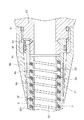
FIG. 8 is a longitudinal cross-sectional view of a portion of a die head of an extrusion molding machine in which a core material covered with a peeling member is coated with an outer skin by extrusion molding. In the following description, the left side in FIG.
[0068]
The die head 7 has a die 71 and a
[0069]
The
[0070]
Inside the die head 7, an outer
[0071]
The
[0072]
A part of the extruded
After the extrusion molding is finished, the cored
[0073]
FIG. 9 is a longitudinal sectional view showing a state in which the metal core is extracted from the core material covered with the outer skin. In FIG. 9, D ″ indicates the outer diameter of the
[0074]
For example, the
The vicinity of both ends of the
[0075]
In addition, since the outer diameter of the
[0076]
Thus, since the outer peripheral surface of the
[0077]
When the endoscope flexible tube 2 is bent, at the bent portion, the
[0078]
On the other hand, if the fixing of the
[0079]
10 is an enlarged longitudinal sectional view showing a part of the longitudinal section shown in FIG.
As shown in FIG. 10, the strip-shaped material forming the
[0080]
The method for covering the outer periphery of the
[0081]
[4] Process for heat-treating the
After the
[0082]
In addition, this heat processing may be performed after the process of removing the outer skin | cover 5 near the edge part of the
[0083]
[5] Step of removing the
FIG. 11 is a diagram illustrating a state after the outer skin and the peeling member in the vicinity of the end portion of the core material are removed.
[0084]
As shown in FIG. 11, the
[0085]
At this time, the
[0086]
At this time, if the vicinity of the core material contact surface of the peeling
[0087]
Moreover, when the vicinity of the outer skin contact surface of the peeling
[0088]
[6] Process of brazing the
The
[0089]
In the present invention, since the heat treatment (vulcanization or the like) of the
[0090]
The endoscope flexible tube 2 manufactured as described above is connected to the
[0091]
FIG. 12 is a longitudinal sectional view of a portion where the endoscope flexible tube is connected to the operation unit. In the following description, the left side in FIG.
[0092]
As shown in FIG. 12, the endoscope flexible tube 2 is connected to the
[0093]
An outer insertion portion 92 having a cylindrical shape is formed at the distal end portion of the
[0094]
The outer periphery of the connection portion between the endoscope flexible tube 2 and the base 91 may be covered with a heat-
[0095]
The
[0096]
FIG. 13 is an enlarged longitudinal sectional view showing another example of the endoscope flexible tube manufactured by the method of the present invention.
[0097]
In the endoscope flexible tube 2 shown in FIG. 13, the
[0098]
Thus, the
[0099]
For example, the
[0100]
Further, by using a material having excellent elasticity for the
[0101]
Further, by using a material having excellent chemical resistance for the
[0102]
The
[0103]
The method for coating the
[0104]
As mentioned above, although the manufacturing method of the flexible tube for endoscopes of this invention was demonstrated based on suitable embodiment shown to an accompanying drawing, this invention is not limited to these.
[0105]
For example, in this embodiment, a tape is used as the peeling
[0106]
In the present embodiment, the outer diameter D of the
[0107]
【The invention's effect】
As described above, according to the present invention, the brazing between the mesh tube and the spiral tube can be performed easily and reliably. For this reason, the flexible tube for endoscopes excellent in the adhesiveness of the mesh tube, the spiral tube, and the outer skin can be manufactured by a relatively simple manufacturing process. In particular, even when it is necessary to heat treat the outer skin, brazing can be used to fix the spiral tube and the mesh tube.
[0108]
In addition, since there is no remaining outer skin near the end of the core material, it is possible to easily attach a base or the like.
[0109]
In addition, when the outer diameter of the spiral tube is smaller than the outer diameter of the spiral tube in the natural state, by covering the outer periphery of the spiral tube with a mesh tube, the adhesion between the spiral tube and the mesh tube (binding force), The adhesion between the spiral tube and the outer skin can be improved.
[0110]
Moreover, the adhesion of the spiral tube, the braided body, and the outer skin is improved by performing the step of covering the outer periphery of the core material so that a part of the outer skin material penetrates into the gaps of the core material.
[0111]
By combining these effects, an endoscope flexible tube having particularly excellent elasticity and durability can be manufactured.
[Brief description of the drawings]
FIG. 1 is an overall view showing an example of a fiber endoscope having a flexible tube for an endoscope manufactured by the method of the present invention.
FIG. 2 is a partial longitudinal sectional view of a core material.
FIG. 3 is a front view showing a natural state of a spiral tube.
FIG. 4 is a front view showing a state in which a spiral tube is temporarily fixed to a cored bar.
FIG. 5 is a side view showing a state in which a spiral tube is temporarily fixed to a cored bar.
FIG. 6 is a front view showing a state in which a mesh tube is coated on the outer periphery of a spiral tube temporarily fixed to a cored bar.
FIG. 7 is a front view showing a state in which the vicinity of the end portion of the core material is covered with a peeling member.
FIG. 8 is a longitudinal cross-sectional view showing a process of covering the core material covered with the release member by extrusion molding.
FIG. 9 is a longitudinal sectional view showing a state in which a metal core is extracted from a core material covered with an outer skin.
10 is an enlarged longitudinal sectional view showing a part of the longitudinal section shown in FIG. 9 in an enlarged manner. FIG.
FIG. 11 is a longitudinal sectional view showing a state after the outer skin and the peeling member in the vicinity of the end portion of the core material are removed.
FIG. 12 is a longitudinal sectional view showing a connecting portion between an endoscope flexible tube and an operation unit.
FIG. 13 is an enlarged longitudinal sectional view of a flexible tube for an endoscope manufactured by the method of the present invention.
[Explanation of symbols]
1 Fiber endoscope
11 Insertion section flexible tube
12 Curved tube
13 Operation unit
14 Eyepiece
15 Light guide flexible tube
16 Light source plug
17 Control lever
18 Light source connector
2 Flexible tube for endoscope
21 outer peripheral surface
3 Core material
31 Spiral tube
311 bent part
312 bending part
313 Return
32 Reticulated tube
321 fine wire
33 Clearance
4 Peeling member
5 outer skin
51 Skin material
52 Inner layer
53 outer layer
6 Wire
7 Dice head
71 dice
72 nipple
73 passage
74 Skin material passage
75 Extrusion port
8 cored bar
81 groove
82 groove
91 base
92 Extrapolation
93 Brazing holes
94 Heat Shrink Tube
95 Fixing screw
96 Presser rubber
97 O-ring
Claims (9)
前記芯材の端部付近の外周に、剥離部材を被覆する工程と、
前記剥離部材で被覆された前記芯材に外皮を被覆する工程と、
前記仮止めを解除して、前記外皮で被覆された前記芯材から、前記芯金を抜き取る工程と、
前記芯材の端部付近における前記外皮を前記剥離部材とともに除去する工程と、
前記外皮の除去により前記芯材が露出した部分において、前記螺旋管と前記編組体とをその端部付近でろう接する工程とを有することを特徴とする内視鏡用可撓管の製造方法。A state in which a cored bar is inserted into a spiral tube formed by spirally winding a band-shaped material, and the spiral tube is temporarily fixed to the cored bar so that an outer diameter of the spiral tube is smaller than an outer diameter in a natural state Then, on the outer periphery of the spiral tube , a step of covering a braided body formed by braiding fine wires and producing a core material;
Coating the peeling member on the outer periphery near the end of the core; and
Covering the core material coated with the release member with an outer skin;
Releasing the temporary fixing and extracting the cored bar from the core coated with the outer skin; and
Removing the outer skin near the end of the core together with the peeling member;
A method of manufacturing a flexible tube for an endoscope, comprising: a step of brazing the spiral tube and the braided body in the vicinity of an end of the portion where the core material is exposed by removing the outer skin.
Priority Applications (1)
| Application Number | Priority Date | Filing Date | Title |
|---|---|---|---|
| JP2000207361A JP4459397B2 (en) | 2000-07-07 | 2000-07-07 | Method for manufacturing flexible tube for endoscope |
Applications Claiming Priority (1)
| Application Number | Priority Date | Filing Date | Title |
|---|---|---|---|
| JP2000207361A JP4459397B2 (en) | 2000-07-07 | 2000-07-07 | Method for manufacturing flexible tube for endoscope |
Publications (2)
| Publication Number | Publication Date |
|---|---|
| JP2002017660A JP2002017660A (en) | 2002-01-22 |
| JP4459397B2 true JP4459397B2 (en) | 2010-04-28 |
Family
ID=18704129
Family Applications (1)
| Application Number | Title | Priority Date | Filing Date |
|---|---|---|---|
| JP2000207361A Expired - Fee Related JP4459397B2 (en) | 2000-07-07 | 2000-07-07 | Method for manufacturing flexible tube for endoscope |
Country Status (1)
| Country | Link |
|---|---|
| JP (1) | JP4459397B2 (en) |
-
2000
- 2000-07-07 JP JP2000207361A patent/JP4459397B2/en not_active Expired - Fee Related
Also Published As
| Publication number | Publication date |
|---|---|
| JP2002017660A (en) | 2002-01-22 |
Similar Documents
| Publication | Publication Date | Title |
|---|---|---|
| JP3835146B2 (en) | Flexible tube and manufacturing method thereof | |
| JP6204085B2 (en) | Endoscopic treatment tool and endoscope system | |
| JP2006507055A (en) | Kink preventing access sheath and method for manufacturing the same | |
| JP2010136834A (en) | Endoscope soft portion and endoscope | |
| JP4566344B2 (en) | Method for manufacturing flexible tube for endoscope | |
| JP5197885B2 (en) | Endoscope | |
| JP2004329857A (en) | Flexible tube for endoscope and its manufacturing method | |
| EP1859725B1 (en) | Endoscope and repair method of endoscope | |
| JP3635965B2 (en) | Method for manufacturing catheter tube | |
| JP4459397B2 (en) | Method for manufacturing flexible tube for endoscope | |
| JP2002125916A (en) | Endoscope | |
| JPH08317986A (en) | Medical tube | |
| JP4459407B2 (en) | Method for manufacturing flexible tube for endoscope | |
| JP2010110444A (en) | Flexible tube for endoscope | |
| JPH11137509A (en) | Flexible tube for endoscope | |
| JP5502005B2 (en) | Endoscope flexible tube and method for assembling endoscope flexible tube | |
| JP4708589B2 (en) | Endoscope flexible tube | |
| JP2006218085A (en) | Medical catheter tube and its manufacturing method | |
| JP3515704B2 (en) | Flexible tube for endoscope and method for manufacturing the same | |
| JP4412776B2 (en) | End of the endoscope | |
| JP2758918B2 (en) | Pipe tube | |
| JP3898941B2 (en) | Method of connecting flexible tube for endoscope and annular connecting member | |
| JP4034078B2 (en) | Endoscopic flexible tube and method for manufacturing endoscope flexible tube | |
| JP2001170180A (en) | Catheter tube and method of manufacturing the same | |
| JP6407376B2 (en) | Endoscopic treatment tool and endoscope system |
Legal Events
| Date | Code | Title | Description |
|---|---|---|---|
| A621 | Written request for application examination |
Free format text: JAPANESE INTERMEDIATE CODE: A621 Effective date: 20070607 |
|
| A711 | Notification of change in applicant |
Free format text: JAPANESE INTERMEDIATE CODE: A712 Effective date: 20080428 |
|
| A131 | Notification of reasons for refusal |
Free format text: JAPANESE INTERMEDIATE CODE: A131 Effective date: 20091110 |
|
| A521 | Written amendment |
Free format text: JAPANESE INTERMEDIATE CODE: A523 Effective date: 20100106 |
|
| TRDD | Decision of grant or rejection written | ||
| A01 | Written decision to grant a patent or to grant a registration (utility model) |
Free format text: JAPANESE INTERMEDIATE CODE: A01 Effective date: 20100202 |
|
| A01 | Written decision to grant a patent or to grant a registration (utility model) |
Free format text: JAPANESE INTERMEDIATE CODE: A01 |
|
| A61 | First payment of annual fees (during grant procedure) |
Free format text: JAPANESE INTERMEDIATE CODE: A61 Effective date: 20100210 |
|
| R150 | Certificate of patent or registration of utility model |
Free format text: JAPANESE INTERMEDIATE CODE: R150 |
|
| FPAY | Renewal fee payment (event date is renewal date of database) |
Free format text: PAYMENT UNTIL: 20130219 Year of fee payment: 3 |
|
| LAPS | Cancellation because of no payment of annual fees |