JP4459313B2 - Extrusion die manufacturing method - Google Patents
Extrusion die manufacturing method Download PDFInfo
- Publication number
- JP4459313B2 JP4459313B2 JP29452597A JP29452597A JP4459313B2 JP 4459313 B2 JP4459313 B2 JP 4459313B2 JP 29452597 A JP29452597 A JP 29452597A JP 29452597 A JP29452597 A JP 29452597A JP 4459313 B2 JP4459313 B2 JP 4459313B2
- Authority
- JP
- Japan
- Prior art keywords
- core
- extrusion die
- die
- electric discharge
- mold
- Prior art date
- Legal status (The legal status is an assumption and is not a legal conclusion. Google has not performed a legal analysis and makes no representation as to the accuracy of the status listed.)
- Expired - Lifetime
Links
Images


Landscapes
- Electrical Discharge Machining, Electrochemical Machining, And Combined Machining (AREA)
Description
【0001】
【発明の属する技術分野】
この発明は、中空材の押出成形に好適に用いられる押出ダイスであって、割れを抑制して長寿命化を図りうる押出ダイスの製造方法に関する。
【0002】
【従来の技術】
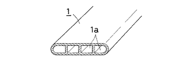
例えば、第1図に示されるような偏平多孔管(1)を押出成形によって製造する場合、一般的には、管内の中空部(1a)を成形する雄型と、管の外周部を成形する雌型との組合わせからなる組合わせダイスが用いられている。そしてさらに、熱交換器用チューブとして使用されるような小型の精巧な偏平多孔管の製造には、小型化されたダイスの製作を容易にするとともに、摩耗等によるダイス交換のコストを抑制するために、雄型において管(1)の中空部(1a)を成形する中子とこの中子を保持する保持用金型とに分割構成された組合わせダイスが用いられている。
【0003】
図2および図3に例示する組合わせダイス(2)において、雌型(3)は、偏平多孔管(1)の外周部を成形する長円偏平状の成形孔(11)を軸芯部に有する雌型本体金型(12)と、該雌型本体金型(12)の後部に隣接配置され、雄型(4)を通過して分断された押出材料同士を合流溶着せしめる溶着室(13)を形成する溶着室形成用金型(14)と、両金型(12)(14)を収容する筒状の収容用金型(15)とからなる。
【0004】
また、雄型(4)において、(21)は中子、(22)は中子保持用金型、(23)は蓋材である。
【0005】
図3示すように、中子(21)は、偏平状で、その先端部に偏平多孔管(1)の中空部(1a)を成形する複数の中空成形部(24)(24)…が櫛状に形成されているとともに、基端部に幅方向に突出する支承用突出部(25)が形成されている。
【0006】
中子保持用金型(22)は、その軸芯部の押出材料導通孔(図示省略)を横断する態様にブリッジ(26)が設けられて、該導通孔が左右の材料導通孔(図示省略)に分断された一体成形の金型である。そして、ブリッジ(25)には、これを押出方向に貫通する態様において、中子(21)を保持する偏平状の中子保持孔(27)が設けられている。この中子保持孔(27)は、基端部において支承用段部(28)(28)が形成され、中子(21)の挿入配置状態において中子(21)の突出部(25)(25)が該支承用段部(28)(28)に支承されるものとなされている。
【0007】
なお、中子保持用金型(22)のブリッジ(26)の後端面は、同金型(22)の内方に退入され、そこに蓋材(23)を嵌合配置する蓋材嵌合用凹部(29)が形成されている。
【0008】
ところで、前記中子(21)の材料には耐摩耗性および耐久性を確保すべく超硬合金等が用いられ、平板状の超硬原盤を所要形状に切り出して製作されるのが一般的である。また、精巧で小型ダイスであることから、櫛状の中空成形部(24)については、加工精度の高いワイヤカット放電加工等の放電加工により切り出される。
【0009】
【発明が解決しようとする課題】
しかしながら、上述の組合わせダイス(2)においては、中子(21)の先端成形部(24)の付け根部分で割れやすいという問題点があった。これは、放電加工の際に加工面に形成された放電変質層が気孔やマイクロクラックを多く含む層であるため、中子表面に超硬本来の材料強度が出ず、押出時の応力が集中する付け根部分で割れるものと推測される。また、放電変質層があると、ダイス使用後の苛性洗浄の際に超硬が溶出し易いため、これも中子の強度低下の原因になっている。
【0010】
この発明は、このような技術背景に鑑み、放電加工により形成されたものでありながら長寿命化を図りうる押出用ダイスの製造方法の提供を目的とする。
【0011】
【課題を解決するための手段】
この発明の押出ダイスの製造方法は、前記目的を達成するために、ダイス用原盤を放電加工により所要形状に切断したのち、加工面に形成された放電変質層を研磨により除去することを特徴とするものである。
【0012】
この発明の方法を適用できるダイスの材質は、通常ダイス材料として用いられ放電加工により切断できるものであれば限定されず、各種超硬合金、各種ダイス鋼を例示できる。
【0013】
放電加工は、ワイヤカット法やグラファイト法など使用する電極の種類は限定されない。しかし、特に精密な小型ダイスの製作には、加工精度が優れている点でワイヤカット法が適している。
【0014】
また、研磨は必ずしも放電加工面の全体に施す必要はなく、押出時の応力が集中して破損し易い部分に施すことによって押出ダイスの長寿命化を図ることができる。例えば、図2および図3に示す組合わせダイス(2)においては、雄型(4)の中子(21)の中空成形部(24)の付け根根元を研磨することによってダイス寿命を延ばすことができる。また、研磨方法も特に限定されるものではなく、エメリー紙による研磨、ダイヤモンドツールによる研磨、ガム研磨、微細なガラスビーズを用いるショットブラスト、超音波ツールによる研磨を例示できる。研磨深さは、放電加工によって形成される放電変質層の厚さが数μm〜数十μm程度であるから、同程度とする。
【0015】
この発明の方法によれば、放電加工により生成された強度の低下した放電変質層が除去されるため、ダイス表面において材料本来の強度が発現する。
【0016】
【実施例】
図2および図3に示す組合わせダイス(2)において、雄型(4)の中子(21)を製作した。中子は、WC−Coからなる厚さ3mmの原盤をワイヤカット放電加工により所要形状に切り出した。
【0017】
そして、実施例においては、ワイヤカット放電加工後に中空成形部(24)(24)間を細長く切ったエメリー紙600#で10分間研磨し、加工面に形成された放電変質層を除去した。一方、比較例においては、同形の中子についてワイヤカット放電加工後何ら研磨処理をしなかった。
【0018】
次に、これらの中子を組合わせダイスに組み込んで、A1100アルミニウムを用いて図1に示す偏平多孔管(1)を押出し、中子が割れるまでのアルミニウム押出量により中子の耐久性を評価した。その結果、実施例の中子は、3回の押出で5000kgの押出が可能であったのに対し、放電変質層を放置した比較例は1回の押出で700kgしか押出すことができなかった。
【0019】
なお、この実施例のように、研磨は少なくとも押出時の応力が集中する中子の中空成形部の付け根部分に施せばダイスの耐久性を向上させることができるが、さらに中子の他の部分や雌型をも研磨することにより、なお一層押出ダイスを割れにくくして耐久性を向上させることができる。
【0020】
【発明の効果】
以上の次第で、この発明の押出ダイスの製造方法は、ダイス用原盤を放電加工により所要形状に切断したのち、加工面に形成された放電変質層を研磨により除去するものであるから、放電加工によって生成された気孔やマイクロクラックが除去されてダイス材料本来の強度が発現し、ダイス寿命を延ばすことができる。
【図面の簡単な説明】
【図1】偏平多孔管の斜視図である。
【図2】中空材を押出す組合わせダイスの横断面図である。
【図3】図2の組合わせダイスの雄型に組み込まれた中子の斜視図である。
【符号の説明】
1…偏平多孔管
2…組合わせダイス
3…雌型
4…雄型
21…中子[0001]
BACKGROUND OF THE INVENTION
The present invention relates to an extrusion die suitably used for extrusion molding of a hollow material, and relates to a method of manufacturing an extrusion die that can suppress cracking and achieve a long life.
[0002]
[Prior art]
For example, when a flat porous tube (1) as shown in FIG. 1 is manufactured by extrusion molding, generally, a male mold for forming a hollow portion (1a) in the tube and an outer peripheral portion of the tube are formed. A combination die comprising a combination with a female die is used. Furthermore, in order to manufacture a small and fine flat porous tube used as a heat exchanger tube, in order to facilitate the manufacture of a miniaturized die and to suppress the cost of die replacement due to wear or the like. In the male mold, a combination die that is divided into a core for forming the hollow portion (1a) of the pipe (1) and a holding mold for holding the core is used.
[0003]
In the combination die (2) illustrated in FIGS. 2 and 3, the female die (3) has an oblong flat forming hole (11) for forming the outer peripheral portion of the flat porous tube (1) at the shaft core portion. A female body body mold (12) having a welding chamber (13) which is disposed adjacent to the rear part of the female body body mold (12) and merges and welds extruded materials separated by passing through the male mold (4). ) Forming a welding chamber forming mold (14) and a cylindrical housing mold (15) for housing both molds (12) and (14).
[0004]
In the male mold (4), (21) is a core, (22) is a core holding mold, and (23) is a lid.
[0005]
As shown in FIG. 3, the core (21) has a flat shape, and a plurality of hollow molding portions (24), (24), which form the hollow portion (1a) of the flat porous tube (1) at its tip portion are combs. And a support protrusion (25) protruding in the width direction is formed at the base end.
[0006]
The core holding mold (22) is provided with a bridge (26) in a mode crossing an extruded material conduction hole (not shown) in the shaft core portion, and the conduction hole is provided on the left and right material conduction holes (not shown). ) Is an integrally formed mold divided into two. The bridge (25) is provided with a flat core holding hole (27) for holding the core (21) in a mode of penetrating the bridge (25) in the extrusion direction. The core holding hole (27) has a support step (28) (28) formed at the base end, and the protruding portion (25) (25) of the core (21) in the inserted arrangement state of the core (21) 25) is supported on the supporting steps (28) (28).
[0007]
The rear end face of the bridge (26) of the core holding mold (22) is retracted inward of the mold (22), and the lid fitting (23) is fitted therein. A combined recess (29) is formed.
[0008]
By the way, as the material of the core (21), cemented carbide or the like is used in order to ensure wear resistance and durability, and it is generally manufactured by cutting a plate-shaped cemented carbide master into a required shape. is there. Moreover, since it is an elaborate and small die | dye, about the comb-shaped hollow shaping | molding part (24), it cuts out by electric discharge machining, such as a wire cut electric discharge machining with high machining precision.
[0009]
[Problems to be solved by the invention]
However, the combination die (2) described above has a problem that it is likely to break at the base portion of the tip forming portion (24) of the core (21). This is because the damaged layer formed on the machined surface during electrical discharge machining is a layer containing many pores and microcracks, so that the original material strength of carbide does not appear on the core surface, and stress during extrusion is concentrated. It is presumed that it breaks at the base part. Further, if there is a discharge altered layer, the carbide is likely to be eluted during caustic cleaning after the use of the die, and this also causes a decrease in the strength of the core.
[0010]
In view of such a technical background, an object of the present invention is to provide a method for producing an extrusion die that can be extended in life while being formed by electric discharge machining.
[0011]
[Means for Solving the Problems]
In order to achieve the above object, the extrusion die manufacturing method of the present invention is characterized in that after the die master is cut into a required shape by electric discharge machining, the discharge altered layer formed on the processed surface is removed by polishing. To do.
[0012]
The material of the die to which the method of the present invention can be applied is not limited as long as it is normally used as a die material and can be cut by electric discharge machining, and examples thereof include various cemented carbides and various die steels.
[0013]
In the electric discharge machining, the type of electrode used, such as a wire cut method or a graphite method, is not limited. However, the wire cutting method is suitable for the manufacture of a particularly precise small die because of its excellent processing accuracy.
[0014]
The polishing is not necessarily applied to the entire electric discharge machined surface, and the life of the extrusion die can be increased by applying it to a portion where stress during extrusion is concentrated and easily damaged. For example, in the combination die (2) shown in FIGS. 2 and 3, the die life can be extended by polishing the root of the hollow molding portion (24) of the core (21) of the male die (4). it can. Also, the polishing method is not particularly limited, and examples include polishing with emery paper, polishing with a diamond tool, gum polishing, shot blasting using fine glass beads, and polishing with an ultrasonic tool. The polishing depth is set to the same level because the thickness of the altered discharge layer formed by electric discharge machining is about several μm to several tens of μm.
[0015]
According to the method of the present invention, the deteriorated discharge deteriorated layer generated by the electric discharge machining is removed, so that the original strength of the material is expressed on the die surface.
[0016]
【Example】
In the combination die (2) shown in FIGS. 2 and 3, the core (21) of the male mold (4) was manufactured. The core was cut into a required shape by wire-cut electric discharge machining of a 3 mm thick master disc made of WC-Co.
[0017]
And in the Example, after wire cut electric discharge machining, it grind | polished for 10 minutes with the emery paper 600 # which cut long between the hollow shaping | molding parts (24) (24), and the electric discharge alteration layer formed in the processed surface was removed. On the other hand, in the comparative example, the core of the same shape was not polished at all after wire-cut electric discharge machining.
[0018]
Next, these cores are assembled into a combination die, the flat porous tube (1) shown in FIG. 1 is extruded using A1100 aluminum, and the durability of the core is evaluated by the amount of aluminum extruded until the core breaks. did. As a result, the core of the example was able to extrude 5000 kg by three extrusions, whereas the comparative example in which the discharge deteriorated layer was allowed to stand could only extrude 700 kg by one extrusion. .
[0019]
In addition, as in this embodiment, polishing can improve the durability of the die if it is applied to the root portion of the hollow molding portion of the core where stress at the time of extrusion is concentrated. Further, polishing the female mold and the female mold can further improve the durability by making the extrusion die difficult to break.
[0020]
【The invention's effect】
As described above, the manufacturing method of the extrusion die according to the present invention is such that after the die master is cut into a required shape by electric discharge machining, the electric discharge deteriorated layer formed on the processed surface is removed by polishing. The pores and microcracks generated by the above are removed, the original strength of the die material is expressed, and the die life can be extended.
[Brief description of the drawings]
FIG. 1 is a perspective view of a flat porous tube.
FIG. 2 is a cross-sectional view of a combination die for extruding a hollow material.
FIG. 3 is a perspective view of a core incorporated in the male die of the combination die of FIG. 2;
[Explanation of symbols]
DESCRIPTION OF SYMBOLS 1 ... Flat
Claims (6)
前記中子を、ダイス用原盤を放電加工により所要形状に切断したのち、加工面のうちの前記中空成形部の付け根根元部分に形成された放電変質層を研磨により除去することによって製造することを特徴とする押出ダイスの製造方法。A male mold for forming a hollow portion in an aluminum flat porous tube includes a core having a plurality of hollow formed portions in a comb shape and a core holding mold, and the male mold and the flat porous tube In the manufacturing method of an extrusion die used for extrusion molding of a flat porous tube composed of a female mold for molding the outer periphery of the tube,
The core is manufactured by cutting a die master into a required shape by electric discharge machining, and then removing the damaged electric discharge layer formed at the base of the hollow molded portion of the processed surface by polishing. A method for producing an extrusion die.
前記中子が、ダイス用原盤を放電加工により所要形状に切断したのち、加工面のうちの前記中空成形部の付け根根元部分に形成された放電変質層を研磨により除去されたものであることを特徴とする押出ダイス。A male mold for forming a hollow portion in an aluminum flat porous tube includes a core having a plurality of hollow formed portions in a comb shape and a core holding mold, and the male mold and the flat porous tube In an extrusion die used for extrusion molding of a flat porous tube composed of a female mold for molding the outer peripheral part of
The core is obtained by cutting the die master into a required shape by electric discharge machining, and then removing the discharge altered layer formed at the base portion of the hollow molded portion of the processed surface by polishing. A featured extrusion die.
Priority Applications (1)
| Application Number | Priority Date | Filing Date | Title |
|---|---|---|---|
| JP29452597A JP4459313B2 (en) | 1997-10-27 | 1997-10-27 | Extrusion die manufacturing method |
Applications Claiming Priority (1)
| Application Number | Priority Date | Filing Date | Title |
|---|---|---|---|
| JP29452597A JP4459313B2 (en) | 1997-10-27 | 1997-10-27 | Extrusion die manufacturing method |
Related Child Applications (1)
| Application Number | Title | Priority Date | Filing Date |
|---|---|---|---|
| JP2008121060A Division JP2008246580A (en) | 2008-05-07 | 2008-05-07 | Manufacturing method of core of extruding die, and core of extruding die |
Publications (2)
| Publication Number | Publication Date |
|---|---|
| JPH11123444A JPH11123444A (en) | 1999-05-11 |
| JP4459313B2 true JP4459313B2 (en) | 2010-04-28 |
Family
ID=17808920
Family Applications (1)
| Application Number | Title | Priority Date | Filing Date |
|---|---|---|---|
| JP29452597A Expired - Lifetime JP4459313B2 (en) | 1997-10-27 | 1997-10-27 | Extrusion die manufacturing method |
Country Status (1)
| Country | Link |
|---|---|
| JP (1) | JP4459313B2 (en) |
Families Citing this family (6)
| Publication number | Priority date | Publication date | Assignee | Title |
|---|---|---|---|---|
| JP4892682B2 (en) * | 2006-12-20 | 2012-03-07 | 国立大学法人 新潟大学 | Surface modification method for wire electrical discharge machining |
| JP2010120020A (en) * | 2008-11-17 | 2010-06-03 | Ykk Ap株式会社 | Method and apparatus for manufacturing extruded shape, and extruded shape |
| JP2009178770A (en) * | 2009-05-08 | 2009-08-13 | Showa Denko Kk | Method of machining mold member, method of producing the same, extrusion die, method for production of extruding material, and extruding material |
| JP5002081B1 (en) * | 2012-02-29 | 2012-08-15 | 株式会社 山一ハガネ | Mold manufacturing method and mold |
| CN110842047A (en) * | 2019-12-09 | 2020-02-28 | 苏州华泰模具制造有限公司 | Extrusion die machining method |
| CN113399943B (en) * | 2021-06-15 | 2022-08-26 | 成都市联余精密机械有限公司 | Processing technology for solving problem of coarse seaming line of PET bottle preform |
-
1997
- 1997-10-27 JP JP29452597A patent/JP4459313B2/en not_active Expired - Lifetime
Also Published As
| Publication number | Publication date |
|---|---|
| JPH11123444A (en) | 1999-05-11 |
Similar Documents
| Publication | Publication Date | Title |
|---|---|---|
| EP0101096B1 (en) | Core and oil-well drill bits | |
| JP4782672B2 (en) | Indexable cutting insert and method of manufacturing the cutting insert | |
| JP2008246580A (en) | Manufacturing method of core of extruding die, and core of extruding die | |
| EP0523170A1 (en) | Safety razor blade. | |
| JPH06315717A (en) | Extrusion molding die and device for said die | |
| JP4459313B2 (en) | Extrusion die manufacturing method | |
| WO2008060019A1 (en) | Diamond tool and method for manufacturing segment thereof | |
| CN209814265U (en) | Unmanned aerial vehicle rotor with micro-structure drag reduction film | |
| KR100366529B1 (en) | Dies for extrusion processing of extruded materials with fine holes | |
| JP2602388B2 (en) | Extrusion dies for hollow metal extrusions | |
| JPH0557337A (en) | Hollow die for extruding cone form | |
| JP4847167B2 (en) | Manufacturing method of tire mold | |
| JP3745504B2 (en) | Die for extruding honeycomb structure and manufacturing method thereof | |
| CN100522511C (en) | Method of manufacturing comb blade used for combing scissors and combing scissors | |
| CN104416229A (en) | PCD (poly-crystal diamond) saw blade and preparation method thereof | |
| JPS61227101A (en) | Extrusion molding machine | |
| CN210526140U (en) | Nested cutter and equipment | |
| JPH08337428A (en) | Glass lens forming mold | |
| JP2003251619A (en) | Base for honeycomb structure and its manufacturing method | |
| JP4467865B2 (en) | Mold member processing method and manufacturing method | |
| JP2800475B2 (en) | Manufacturing method of diamond core bit | |
| CN217343982U (en) | Electrode cap grinding and shaping cutter | |
| JP2510764B2 (en) | Manufacturing method of cemented carbide die | |
| JP2510566Y2 (en) | Knife sharpener | |
| JPS6114824A (en) | Method of manufacturing mold with extremely small odd-shaped hole |
Legal Events
| Date | Code | Title | Description |
|---|---|---|---|
| A521 | Written amendment |
Free format text: JAPANESE INTERMEDIATE CODE: A523 Effective date: 20041021 |
|
| A621 | Written request for application examination |
Free format text: JAPANESE INTERMEDIATE CODE: A621 Effective date: 20041021 |
|
| A977 | Report on retrieval |
Free format text: JAPANESE INTERMEDIATE CODE: A971007 Effective date: 20070425 |
|
| A131 | Notification of reasons for refusal |
Free format text: JAPANESE INTERMEDIATE CODE: A131 Effective date: 20071218 |
|
| A521 | Written amendment |
Free format text: JAPANESE INTERMEDIATE CODE: A523 Effective date: 20080208 |
|
| A02 | Decision of refusal |
Free format text: JAPANESE INTERMEDIATE CODE: A02 Effective date: 20080311 |
|
| A521 | Written amendment |
Free format text: JAPANESE INTERMEDIATE CODE: A523 Effective date: 20080502 |
|
| A911 | Transfer of reconsideration by examiner before appeal (zenchi) |
Free format text: JAPANESE INTERMEDIATE CODE: A911 Effective date: 20080519 |
|
| A912 | Removal of reconsideration by examiner before appeal (zenchi) |
Free format text: JAPANESE INTERMEDIATE CODE: A912 Effective date: 20080613 |
|
| A01 | Written decision to grant a patent or to grant a registration (utility model) |
Free format text: JAPANESE INTERMEDIATE CODE: A01 |
|
| A61 | First payment of annual fees (during grant procedure) |
Free format text: JAPANESE INTERMEDIATE CODE: A61 Effective date: 20100210 |
|
| R150 | Certificate of patent or registration of utility model |
Free format text: JAPANESE INTERMEDIATE CODE: R150 |
|
| FPAY | Renewal fee payment (event date is renewal date of database) |
Free format text: PAYMENT UNTIL: 20130219 Year of fee payment: 3 |
|
| FPAY | Renewal fee payment (event date is renewal date of database) |
Free format text: PAYMENT UNTIL: 20130219 Year of fee payment: 3 |
|
| RD02 | Notification of acceptance of power of attorney |
Free format text: JAPANESE INTERMEDIATE CODE: R3D02 |
|
| FPAY | Renewal fee payment (event date is renewal date of database) |
Free format text: PAYMENT UNTIL: 20160219 Year of fee payment: 6 |
|
| EXPY | Cancellation because of completion of term |