JP4459237B2 - Process for producing 3-pentenenitrile from 1,3-butadiene - Google Patents
Process for producing 3-pentenenitrile from 1,3-butadiene Download PDFInfo
- Publication number
- JP4459237B2 JP4459237B2 JP2006550103A JP2006550103A JP4459237B2 JP 4459237 B2 JP4459237 B2 JP 4459237B2 JP 2006550103 A JP2006550103 A JP 2006550103A JP 2006550103 A JP2006550103 A JP 2006550103A JP 4459237 B2 JP4459237 B2 JP 4459237B2
- Authority
- JP
- Japan
- Prior art keywords
- stream
- butadiene
- column
- weight
- pentenenitrile
- Prior art date
- Legal status (The legal status is an assumption and is not a legal conclusion. Google has not performed a legal analysis and makes no representation as to the accuracy of the status listed.)
- Expired - Fee Related
Links
- XHYACLIGVSHHPL-UHFFFAOYSA-N Cc(cc1-c2c3OP(Oc4ccccc4C)Oc4ccccc4Cc3cc(C)c2)cc2c1OP(Oc1c(C)cccc1)Oc1ccccc1C2 Chemical compound Cc(cc1-c2c3OP(Oc4ccccc4C)Oc4ccccc4Cc3cc(C)c2)cc2c1OP(Oc1c(C)cccc1)Oc1ccccc1C2 XHYACLIGVSHHPL-UHFFFAOYSA-N 0.000 description 1
Images


Classifications
-
- C—CHEMISTRY; METALLURGY
- C07—ORGANIC CHEMISTRY
- C07C—ACYCLIC OR CARBOCYCLIC COMPOUNDS
- C07C253/00—Preparation of carboxylic acid nitriles
- C07C253/08—Preparation of carboxylic acid nitriles by addition of hydrogen cyanide or salts thereof to unsaturated compounds
- C07C253/10—Preparation of carboxylic acid nitriles by addition of hydrogen cyanide or salts thereof to unsaturated compounds to compounds containing carbon-to-carbon double bonds
-
- C—CHEMISTRY; METALLURGY
- C07—ORGANIC CHEMISTRY
- C07C—ACYCLIC OR CARBOCYCLIC COMPOUNDS
- C07C255/00—Carboxylic acid nitriles
- C07C255/01—Carboxylic acid nitriles having cyano groups bound to acyclic carbon atoms
- C07C255/06—Carboxylic acid nitriles having cyano groups bound to acyclic carbon atoms of an acyclic and unsaturated carbon skeleton
- C07C255/07—Mononitriles
Description
本発明は、3−ペンテンニトリルを製造する方法に関する。 The present invention relates to a method for producing 3-pentenenitrile.
アジポニトリルは、ナイロンの製造において重要な出発材料であり、そして、アジポニトリルは、1,3−ブタジエンの二重シアン化水素処理によって得ることができる。第1のシアン化水素処理において、1,3−ブタジエンは、3−ペンテンニトリルにシアン化水素処理され、そして得られる副生成物は、主に2−メチル−3−ブテンニトリル、4−ペンテンニトリル、2−ペンテンニトリル、2−メチル−2−ブテンニトリル、C9ニトリル、及びメチルグルタロニトリルである。続く第2のシアン化水素処理において、3−ペンテンニトリルはシアン化水素と反応し、アジポニトリルが得られる。シアン化水素処理は両方とも、ニッケル(0)−燐錯体によって触媒作用が及ぼされる。 Adiponitrile is an important starting material in the production of nylon and adiponitrile can be obtained by double hydrocyanation of 1,3-butadiene. In the first hydrocyanide treatment, 1,3-butadiene is hydrocyanated to 3-pentenenitrile, and the resulting by-products are mainly 2-methyl-3-butenenitrile, 4-pentenenitrile, 2-pentenenitrile. nitrile, 2-methyl-2-butenenitrile, C 9 nitriles and methylglutaronitrile. In the subsequent second hydrogen cyanide treatment, 3-pentenenitrile reacts with hydrogen cyanide to give adiponitrile. Both hydrocyanation treatments are catalyzed by nickel (0) -phosphorus complexes.
第2のシアン化水素処理のために、使用する3−ペンテンニトリルは、2−メチル−3−ブテンニトリルが本質的に除去されているが、これは除去されていなければ、2−メチル−3−ブテンニトリルは、望ましくない副生成物であるメチルグルタロニトリルにシアン化水素処理されるからである。 For the second hydrocyanide treatment, the 3-pentenenitrile used is essentially free of 2-methyl-3-butenenitrile, but if this is not removed, 2-methyl-3-butenenitrile is used. This is because nitrile is hydrocyanated to methyl glutaronitrile, which is an undesirable by-product.
ニッケル−触媒作用下のオレフィンシアン化水素処理の概論がAdv.Cat.33,1−46(1985),Tolmanらによって与えられている。 An overview of nickel-catalyzed olefin hydrocyanide treatment is given in Adv. Cat. 33, 1-46 (1985), Tolman et al.
式Ni[P(OR)3]4のニッケル触媒を使用した1,3−ブタジエンのシアン化水素処理が、US3496215に記載されている。この方法の不利な点は、1,3−ブタジエン又は触媒を完全に回収する適切な技術が記載されていないことである。 The hydrocyanide treatment of 1,3-butadiene using a nickel catalyst of the formula Ni [P (OR) 3 ] 4 is described in US Pat. The disadvantage of this method is that no suitable technique for complete recovery of 1,3-butadiene or catalyst has been described.
特許文献1(US5693843)、特許文献2(US5696280)、特許文献3(US5821378)、及び特許文献4(US5981772)には、1,3−ブタジエンの多座配位の燐配位子とのシアン化水素処理が記載されているが、個々の実施の形態には、触媒成分を回収するための適切な手順が記載されていない。 In Patent Document 1 (US5693843), Patent Document 2 (US5696280), Patent Document 3 (US5821378), and Patent Document 4 (US5981772), hydrogen cyanide treatment with a polydentate phosphorus ligand of 1,3-butadiene However, the individual embodiments do not describe an appropriate procedure for recovering the catalyst components.
1個以上の反応器におけるシアン化水素処理の実施、及びこれらの結合がUS4810815に記載されており、同文献には、攪拌タンク又は一群の攪拌タンクの連続操作が可能であると述べられているが、実施例には半バッチ(semibatch)形式のものしか記載されておらず、半バッチ形式の操作からでは、当業者は、複数の連続的な攪拌タンクにおいてこの方法を進行させるべき条件を直接的に認識することができない。 Implementation of hydrocyanide treatment in one or more reactors and their combination are described in US 4,810,815, which states that a stirred tank or a group of stirred tanks can be operated continuously, The examples only describe the semi-batch format, and from the semi-batch mode of operation, one skilled in the art can directly determine the conditions under which the process should proceed in a plurality of continuous stirred tanks. It cannot be recognized.
オレフィンのシアン化水素処理において、有機燐化合物及びこの金属錯体を有機ニトリルから除去する方法が、特許文献5(US3773809)に記載されている。この除去は、生成物をシクロパラフィン又はパラフィン性炭化水素に接触させることにより行なわれている。これは液体多相組成物を形成する。反応生成物中のジニトリルの濃度が非常に低いので、この抽出による触媒成分の除去と回収手段は、1,3−ブタジエンのシアン化水素処理には適用することができない。 In the hydrogen cyanide treatment of olefins, Patent Document 5 (US3773809) describes a method for removing an organic phosphorus compound and this metal complex from an organic nitrile. This removal is done by contacting the product with cycloparaffins or paraffinic hydrocarbons. This forms a liquid multiphase composition. Since the concentration of dinitrile in the reaction product is very low, the catalyst component removal and recovery means by this extraction cannot be applied to the 1,3-butadiene hydrocyanide treatment.
更に、1,3−ブタジエンとシアン化水素処理触媒流の両方が再循環される3−ペンテンニトリルの総合的な製造方法にとって、シアン化水素に対してモル量で過剰に使用される1,3−ブタジエンが効率的に再循環されるということは、重要なことである。 In addition, for a comprehensive process for the production of 3-pentenenitrile in which both 1,3-butadiene and the hydrocyanide treatment catalyst stream are recycled, 1,3-butadiene used in molar amounts relative to hydrogen cyanide is efficient. It is important to be recycled.
従って、本発明の目的は、1,3−ブタジエンをシアン化水素処理することにより3−ペンテンニトリルを製造する総合敵な方法を提供することにあり、そして、この方法は、市販のブタジエンが、シアン化水素処理において非反応性でありブタジエン循環中で蓄積するシス−2−ブテンを含み、従って、1,3−ブタジエンの強制排出と関連して、シス−2−ブテンを排出しなければならない場合であっても、1,3−ブタジエンに関する工程収率が可能な限り高くなるものである。 Accordingly, it is an object of the present invention to provide a comprehensive enemy process for the production of 3-pentenenitrile by hydrocyanating 1,3-butadiene and the process is such that commercially available butadiene is treated with hydrocyanide. In which cis-2-butene must be discharged in conjunction with forced discharge of 1,3-butadiene. The process yield for 1,3-butadiene is as high as possible.
本発明に従う方法は、従って、排出による1,3−ブタジエンの損失が少ないという特徴を有している。 The process according to the invention is therefore characterized by a low loss of 1,3-butadiene due to emissions.
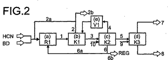
この目的は、1,3−ブタジエンをシアン化水素処理することにより3−ペンテンニトリルを製造する方法であって、以下の工程、
(a)シス−2−ブテンを含む1,3−ブタジエンを、少なくとも1種の触媒の存在下にシアン化水素と反応させて3−ペンテンニトリル、2−メチル−3−ブテンニトリル、前記少なくとも1種の触媒、1,3−ブタジエン及び未転化のシアン化水素を含む流れ1を得る工程、
(b)蒸留装置K1内で流れ1を蒸留し、塔頂生成物として、流れ1から得られる1,3−ブタジエンの大部分を含む流れ2を得、そして塔底生成物として、3−ペンテンニトリル、少なくとも1種の前記触媒、2−メチル−3−ブテンニトリル、及び流れ2に移動しなかった流れ1からの1,3−ブタジエンの残留部分を含む流れ3を得る工程、
(c)蒸留装置K2内で流れ3を蒸留し、1,3−ブタジエンを含む塔頂生成物としての流れ4を得、カラムの側部排出部にて、3−ペンテンニトリル及び2−メチル−3−ブテンニトリルを含む流れ5を得、そして塔底生成物として少なくとも1種の前記触媒を含む流れ6を得、
(d)流れ5を蒸留し、塔頂生成物として2−メチル−3−ブテンニトリルを含む流れ7を得、そして塔底部として3−ペンテンニトリルを含む流れ8を得る工程、
を含み、且つ、
工程(b)で使用された蒸留装置K1が、ストリッピング区分を有する少なくとも1基の蒸留カラムを含み、及び/又は、
工程(c)で使用された蒸留装置K2が、流れ3の供給部と流れ5の排出部との間に蒸留分離段を有し、及び流れ5の排出部が、蒸留装置K2において、流れ3の供給部よりも低い位置に配置されていることを特徴とする方法によって達成される。
This object is a method for producing 3-pentenenitrile by treating 1,3-butadiene with hydrogen cyanide, comprising the following steps:
(A) 1,3-butadiene containing cis-2-butene is reacted with hydrogen cyanide in the presence of at least one catalyst to produce 3-pentenenitrile, 2-methyl-3-butenenitrile, the at least one Obtaining
(B) Distilling
(C)
(D) distilling
And including
The distillation apparatus K1 used in step (b) comprises at least one distillation column having a stripping section and / or
The distillation apparatus K2 used in step (c) has a distillation separation stage between the feed section of
流れ1の1,3−ブタジエンの大部分として上述した、流れ1の1,3−ブタジエンの部分は、流れ2と共に排出されることになり、そして、流れ1のこの排出される1,3−ブタジエンの割合は、流れ1の1,3−ブタジエンの好ましくは50%以上、より好ましくは60%以上、特に70%以上である。これに対応して、流れ1に残っている1,3−ブタジエンは、工程(c)において、流れ3を介して移行する。
The portion of 1,3-butadiene in
工程(a)は、少なくとも1種の触媒上での1,3−ブタジエンのシアン化水素との反応を含む。使用する触媒は、均一に溶解したニッケル(0)触媒錯体である。 Step (a) comprises the reaction of 1,3-butadiene with hydrogen cyanide over at least one catalyst. The catalyst used is a uniformly dissolved nickel (0) catalyst complex.
燐配位子及び/又は遊離(free)燐配位子を含むNi(0)錯体は、好ましくは、均一に溶解したニッケル(0)錯体である。 The Ni (0) complex containing a phosphorus ligand and / or a free phosphorus ligand is preferably a uniformly dissolved nickel (0) complex.
ニッケル(0)錯体の燐配位子、及び遊離燐配位子は、好ましくは、単座−又は二座のホスフィン、ホスファイト、ホスフィナイト(phosphinite)、及びホスホナイト(phosphonite)から選ばれる。 The phosphorus ligand of the nickel (0) complex and the free phosphorus ligand are preferably selected from monodentate- or bidentate phosphines, phosphites, phosphinites, and phosphonites.
これら燐配位子は、式I:
P(X1R1)(X2R2)(X3R3) (I)
を有していることが好ましい。
These phosphorus ligands have the formula I:
P (X 1 R 1 ) (X 2 R 2 ) (X 3 R 3 ) (I)
It is preferable to have.
本発明において、化合物Iは、単一の化合物又は上記式の異なる化合物の混合物である。 In the context of the present invention, compound I is a single compound or a mixture of different compounds of the above formula.
本発明では、X1、X2、X3は、それぞれ独立して酸素又は単一結合である。全てのX1、X2、X3基が単一結合である場合、化合物Iは、式P(R1R2R3)(但し、R1R2及びR3の定義は、本願明細書に記載されたものである。)のホスフィンである。 In the present invention, X 1 , X 2 and X 3 are each independently oxygen or a single bond. When all X 1 , X 2 , X 3 groups are a single bond, compound I can be represented by the formula P (R 1 R 2 R 3 ) (provided that R 1 R 2 and R 3 are defined herein) Phosphine).
X1、X2、及びX3基の2個が、単一結合であり、そして1個が酸素の場合、化合物Iは、式P(OR1)(R2)(R3)又はP(R1)(OR2)(R3)又は式P(R1)(R2)(OR3)(但し、R1、R2及びR3の定義は、本願明細書に記載されたものである。)のホスフィナイトである。 When two of the X 1 , X 2 , and X 3 groups are a single bond and one is oxygen, the compound I can be represented by the formula P (OR 1 ) (R 2 ) (R 3 ) or P ( R 1 ) (OR 2 ) (R 3 ) or the formula P (R 1 ) (R 2 ) (OR 3 ) (provided that the definitions of R 1 , R 2 and R 3 are those described in the present specification). Phosphinite).
X1、X2、及びX3基の1個が、単一結合であり、そして2個が酸素の場合、化合物Iは、式P(OR1)(OR2)(R3)又はP(R1)(OR2)(OR3)又は式P(OR1)(R2)(OR3)(但し、R1R2及びR3の定義は、本願明細書に記載されたものである。)のホスホナイトである。 When one of the X 1 , X 2 , and X 3 groups is a single bond and two are oxygen, compound I can be represented by the formula P (OR 1 ) (OR 2 ) (R 3 ) or P ( R 1 ) (OR 2 ) (OR 3 ) or the formula P (OR 1 ) (R 2 ) (OR 3 ) (provided that the definitions of R 1 R 2 and R 3 are those described herein) .) Phosphonite.
好ましい実施の形態では、全てのX1、X2、及びX3基が酸素であり、従って化合物Iは、式P(OR1)(OR2)(OR3)(但し、R1R2及びR3の定義は、以下に記載されたものである。)のホスファイトである。 In a preferred embodiment, all X 1 , X 2 , and X 3 groups are oxygen, so that Compound I has the formula P (OR 1 ) (OR 2 ) (OR 3 ) (where R 1 R 2 and The definition of R 3 is as described below).
本発明に従えば、R1、R2、R3は、それぞれ独立して、同一又は異なる有機基(organic radical)である。R1、R2、R3は、それぞれ独立して、メチル、エチル、n−プロピル、i−プロピル、n−ブチル、i−ブチル、s−ブチル、t−ブチル等の好ましくは1〜10個の炭素原子を有するアルカリ基、フェニル、o−トリル、m−トリル、p−トリル、1−ナフチル、2−ナフチル等のアリール基、又は1,1’−ビフェノール、1,1’−ビナフトール等の、好ましくは1〜20個の炭素原子を有するヒドロカルビルである。R1、R2及びR3基は互いに直接的に結合していても良く、すなわち、中心の燐原子を介して結合している場合に限られない。R1、R2及びR3基が互いに直接的に結合していないことが好ましい。 According to the present invention, R 1 , R 2 , R 3 are each independently the same or different organic radicals. R 1 , R 2 , R 3 are each independently preferably 1-10, such as methyl, ethyl, n-propyl, i-propyl, n-butyl, i-butyl, s-butyl, t-butyl, etc. Or an aryl group such as phenyl, o-tolyl, m-tolyl, p-tolyl, 1-naphthyl, 2-naphthyl, or 1,1′-biphenol, 1,1′-binaphthol, etc. , Preferably hydrocarbyl having 1 to 20 carbon atoms. The R 1 , R 2 and R 3 groups may be bonded directly to each other, i.e. not limited to being bonded via a central phosphorus atom. It is preferred that the R 1 , R 2 and R 3 groups are not directly bonded to each other.
好ましい実施の形態では、R1、R2及びR3基は、フェニル、o−トリル、m−トリル、及びp−トリルから成る群から選ばれる基である。特に好ましい実施の形態では、R1、R2及びR3基の最大2個がフェニル基であるべきである。 In a preferred embodiment, R 1, R 2 and R 3 groups, phenyl, o- tolyl, a group selected from the group consisting of m- tolyl and p- tolyl. In a particularly preferred embodiment, at most two of the R 1 , R 2 and R 3 groups should be phenyl groups.
他の好ましい実施の形態では、R1、R2及びR3基の最大2個がo−トリル基であるべきである。 In other preferred embodiments, at most two of the R 1 , R 2 and R 3 groups should be o-tolyl groups.
使用して良い特に好ましい化合物は、式Ia、
(o−トリル−O−)w(m−トリル−O−)x(p−トリル−O−)y(フェニル−O−)zP (Ia)
(但し、w、x、y、zがそれぞれ自然数であり、及び次の定義が適用される:w+x+y+z=3 and w、z≦2。)の化合物である。
Particularly preferred compounds that may be used are those of formula Ia,
(O-tolyl-O-) w (m-tolyl-O-) x (p-tolyl-O-) y (phenyl-O-) z P (Ia)
(Where w, x, y and z are natural numbers, respectively, and the following definition applies: w + x + y + z = 3 and w, z ≦ 2.).
このような化合物Iaは、例えば、(p−トリル−O−)(フェニル−O−)2P、(m−トリル−O−)(フェニル−O−)2P、(o−トリル−O−)(フェニル−O−)2P、(p−トリル−O−)2(フェニル−O−)P、(m−トリル−O−)2(フェニル−O−)P、(o−トリル−O−)2(フェニル−O−)P、(m−トリル−O−)(p−トリル−O−)(フェニル−O−)P、(o−トリル−O−)(p−トリル−O−)(フェニル−O−)P、(o−トリル−O−)(m−トリル−O−)(フェニル−O−)P、(p−トリル−O−)3P、(m−トリル−O−)(p−トリル−O−)2P、(o−トリル−O−)(p−トリル−O−)2P、(m−トリル−O−)2(p−トリル−O−)P、(o−トリル−O−)2(p−トリル−O−)P、(o−トリル−O−)(m−トリル−O−)(p−トリル−O−)P、(m−トリル−O−)3P、(o−トリル−O−)(m−トリル−O−)2P、(o−トリル−O−)2(m−トリル−O−)P、又はこのような化合物の混合物である。 Such compounds Ia are, for example, (p-tolyl-O-) (phenyl-O-) 2 P, (m-tolyl-O-) (phenyl-O-) 2 P, (o-tolyl-O- ) (phenyl -O-) 2 P, (p-tolyl -O-) 2 (phenyl -O-) P, (m-tolyl -O-) 2 (phenyl -O-) P, (o-tolyl -O -) 2 (phenyl-O-) P, (m-tolyl-O-) (p-tolyl-O-) (phenyl-O-) P, (o-tolyl-O-) (p-tolyl-O-) ) (Phenyl-O-) P, (o-tolyl-O-) (m-tolyl-O-) (phenyl-O-) P, (p-tolyl-O-) 3 P, (m-tolyl-O -) (P-tolyl-O-) 2 P, (o-tolyl-O-) (p-tolyl-O-) 2 P, (m-tolyl-O-) 2 (p-tolyl-O-) P , (O-tolyl-O-) 2 (p-tolyl-O-) P, (o-tolyl-O-) (m-tolyl-O-) (p-tolyl-O-) P, (m-tolyl-O-) 3 P, (o -Tolyl-O-) (m-tolyl-O-) 2 P, (o-tolyl-O-) 2 (m-tolyl-O-) P, or a mixture of such compounds.
例えば、原油(crude oil)の蒸留加工物中に得られるm−クレゾール及びp−クレゾールを、特にモル比が2:1の割合で含む混合物を、燐トリクロリド等の燐トリハロゲン化物と反応させることによって、(m−トリル−O−)3P、(m−トリル−O−)2(p−トリル−O−)P、(m−トリル−O−)(p−トリル−O−)2P、及び(p−トリル−O−)3Pの混合物が得られる。 For example, reacting a mixture comprising m-cresol and p-cresol obtained in a crude oil distillation process, particularly in a molar ratio of 2: 1, with a phosphorus trihalide such as phosphorus trichloride. (M-tolyl-O-) 3 P, (m-tolyl-O-) 2 (p-tolyl-O-) P, (m-tolyl-O-) (p-tolyl-O-) 2 P And a mixture of (p-tolyl-O-) 3 P is obtained.
他の同様な好ましい実施の形態では、燐配位子は、DE−A19953058に詳細に記載されたホスファイトで、このホスファイトは式Ib
P(O−R1)x(O−R2)y(O−R3)z(O−R4)p (Ib)
(但し、
R1:燐原子を芳香族系に結合させる酸素原子に対してo−位に、C1−C18−アルキル置換基を有する芳香族基、又は燐原子を芳香族系に結合させる酸素原子に対してo−位に、芳香族置換基を有する芳香族基、又は燐原子を芳香族系に結合させる酸素原子に対してo−位に、融解芳香族系(fused aromatic system)を有する芳香族基、
R2:燐原子を芳香族系に結合させる酸素原子に対してm−位に、C1−C18−アルキル置換基を有する芳香族基、又は燐原子を芳香族系に結合させる酸素原子に対してm−位に、芳香族置換基を有する芳香族基、又は燐原子を芳香族系に結合させる酸素原子に対してm−位に、融解芳香族系(fused aromatic system)を有する芳香族基で、芳香族基は、燐原子を芳香族系に結合させる酸素原子に対してo−位に水素原子を帯びている、
R3:燐原子を芳香族系に結合させる酸素原子に対してp−位に、C1−C18−アルキル置換基を有する芳香族基、又は燐原子を芳香族系に結合させる酸素原子に対してp−位に、芳香族置換基を有する芳香族基で、芳香族基は、燐原子を芳香族系に結合させる酸素原子に対してo−位に水素原子を帯びている、
R4:R1、R2及びR3以外の置換基を、燐原子を芳香族系に結合させる酸素原子に対してo−、m−及びp−位に帯びている芳香族基で、芳香族基は、燐原子を芳香族系に結合させる酸素原子に対してo−位に水素原子を帯びている、
x:1又は2
y、z、p:それぞれが独立して0、1又は2(但し、x+y+z=3である。)
である。)のホスファイトである。
In another similar preferred embodiment, the phosphorus ligand is a phosphite described in detail in DE-A 19953058, which phosphite has the formula Ib
P (O—R 1 ) x (O—R 2 ) y (O—R 3 ) z (O—R 4 ) p (Ib)
(However,
R 1 : An aromatic group having a C 1 -C 18 -alkyl substituent, or an oxygen atom that binds the phosphorus atom to the aromatic system in the o-position relative to the oxygen atom that bonds the phosphorus atom to the aromatic system An aromatic group having an aromatic substituent at the o-position or an aromatic group having a fused aromatic system at the o-position with respect to an oxygen atom that binds a phosphorus atom to the aromatic system. Group,
R 2 : an aromatic group having a C 1 -C 18 -alkyl substituent, or an oxygen atom that binds a phosphorus atom to an aromatic system in the m-position relative to the oxygen atom that binds the phosphorus atom to the aromatic system An aromatic group having an aromatic substituent in the m-position, or an aromatic group having a fused aromatic system in the m-position with respect to an oxygen atom that binds a phosphorus atom to the aromatic system. The aromatic group has a hydrogen atom in the o-position relative to the oxygen atom that bonds the phosphorus atom to the aromatic system;
R 3 : an aromatic group having a C 1 -C 18 -alkyl substituent, or an oxygen atom that binds a phosphorus atom to the aromatic system in the p-position relative to the oxygen atom that binds the phosphorus atom to the aromatic system On the other hand, in the p-position, the aromatic group has an aromatic substituent, and the aromatic group has a hydrogen atom in the o-position with respect to the oxygen atom that bonds the phosphorus atom to the aromatic system.
R 4 : Substituents other than R 1 , R 2 and R 3 are aromatic groups having o-, m- and p-positions with respect to the oxygen atom which binds the phosphorus atom to the aromatic system. The group has a hydrogen atom in the o-position relative to the oxygen atom that bonds the phosphorus atom to the aromatic system;
x: 1 or 2
y, z, p: each independently 0, 1 or 2 (provided that x + y + z = 3)
It is. ) Phosphite.
式Ibの好ましいホスファイトは、DE−A19953058から得ることができる。R1基は、o−トリル、o−エチルフェニル、o−n−プロピルフェニル、o−イソプロピルフェニル、o−n−ブチルフェニル、o−sec−ブチルルフェニル、o−tert−ブチルルフェニル、(o−フェニル)フェニル又は1−ナフチル基が有利である。 A preferred phosphite of the formula Ib can be obtained from DE-A 19953058. R 1 group includes o-tolyl, o-ethylphenyl, on-propylphenyl, o-isopropylphenyl, on-butylphenyl, o-sec-butyllphenyl, o-tert-butyllphenyl, ( An o-phenyl) phenyl or 1-naphthyl group is preferred.
好ましいR2基は、m−トリル、m−エチルフェニル、m−n−プロピルフェニル、m−イソプロピルフェニル、m−n−ブチルフェニル、m−sec−ブチルフェニル、m−tert−ブチルフェニル、(m−フェニル)フェニル又は2−ナフチル基である。 Preferred R 2 groups are m-tolyl, m-ethylphenyl, mn-propylphenyl, m-isopropylphenyl, mn-butylphenyl, m-sec-butylphenyl, m-tert-butylphenyl, (m -Phenyl) phenyl or 2-naphthyl group.
有利なR3基は、p−トリル、p−エチルフェニル、p−n−プロピルフェニル、p−イソプロピルフェニル、p−n−ブチルフェニル、p−sec−ブチルフェニル、p−tert−ブチルフェニル又は(p−フェニル)フェニル基である。 Preferred R 3 groups are p-tolyl, p-ethylphenyl, pn-propylphenyl, p-isopropylphenyl, pn-butylphenyl, p-sec-butylphenyl, p-tert-butylphenyl or ( p-phenyl) phenyl group.
R4基は、フェニルが好ましい。pはゼロが好ましい。化合物Ib中の指数x、y、z及びpに関し、以下のものが可能である。 The R 4 group is preferably phenyl. p is preferably zero. Regarding the indices x, y, z and p in compound Ib, the following are possible:

式Ibの好ましいホスファイトは、pがゼロであり、及びR1、R2及びR3がそれぞれ独立して、o−イソプロピルフェニル、m−トリル及びp−トリルであり、及びR4がフェニルであるものである。 Preferred phosphites of formula Ib are wherein p is zero, and R 1 , R 2 and R 3 are each independently o-isopropylphenyl, m-tolyl and p-tolyl, and R 4 is phenyl There is something.
式Ibの好ましいホスファイトは、R1がo−イソプロピルフェニル基、R2がm−トリル基、及びR3がp−トリル基で、上述した表に記載した指数を有するものであり、また、R1がo−トリル基、R2がm−トリル基、及びR3がp−トリル基で、上述した表に記載した指数を有するものであり、追加的に、R1が1−ナフチル基、R2がm−トリル基、及びR3がp−トリル基で、上述した表に記載した指数を有するものであり、及び、R1がo−トリル基、R2が2−ナフチル基、及びR3がp−トリル基で、上述した表に記載した指数を有するものでもあり、そして、最後に、R1がo−イソプロピルフェニル基、R2が2−ナフチル基、及びR3がp−トリル基で、上述した表に記載した指数を有するものであり、及びこれらホスファイトの混合物でもある。 Preferred phosphites of formula Ib are those in which R 1 is an o-isopropylphenyl group, R 2 is an m-tolyl group, and R 3 is a p-tolyl group and has the indices listed in the table above, and R 1 is an o-tolyl group, R 2 is an m-tolyl group, and R 3 is a p-tolyl group, and has an index described in the above-mentioned table, and additionally, R 1 is a 1-naphthyl group. , R 2 is an m-tolyl group, and R 3 is a p-tolyl group, and has the index described in the above table, and R 1 is an o-tolyl group, R 2 is a 2-naphthyl group, And R 3 is a p-tolyl group and also has the index described in the above table, and finally R 1 is an o-isopropylphenyl group, R 2 is a 2-naphthyl group, and R 3 is p. A tolyl group having an index as described in the table above, and these phosphines There is also a mixture of.
式Ibのホスファイトは、以下の工程
a)燐トリハロゲン化物とR1OH、R2OH、R3OH及びR4OH又はこれらの混合物からなる群から選ばれるアルコールとを反応させ、ジハロホスホラスモノエステルを得る工程、
b)上記ジハロホスホラスモノエステルとR1OH、R2OH、R3OH及びR4OH又はこれらの混合物からなる群から選ばれるアルコールとを反応させ、モノハロホスホラスジエステルを得る工程、及び
c)上記モノハロホスホラスジエステルとR1OH、R2OH、R3OH及びR4OH又はこれらの混合物からなる群から選ばれるアルコールとを反応させ、式Ibのホスファイトを得る工程、
によって得ても良い。
The phosphite of formula Ib is obtained by reacting the following step a) phosphorus trihalide with an alcohol selected from the group consisting of R 1 OH, R 2 OH, R 3 OH and R 4 OH or mixtures thereof: Obtaining a phosphorous monoester;
b) reacting the dihalophosphorus monoester with an alcohol selected from the group consisting of R 1 OH, R 2 OH, R 3 OH and R 4 OH or a mixture thereof to obtain a monohalophosphorous diester; And c) reacting the monohalophosphorous diester with an alcohol selected from the group consisting of R 1 OH, R 2 OH, R 3 OH and R 4 OH or mixtures thereof to obtain a phosphite of formula Ib;
You may get by.
反応は、別々になった3工程で行なってよい。同様に、3工程の内の2工程を結合しても良い、すなわち、a)とb)、又はb)とc)を結合しても良い。この代わりに、全工程a)、b)及びc)を一緒に結合しても良い。 The reaction may be performed in three separate steps. Similarly, two of the three steps may be combined, that is, a) and b) or b) and c) may be combined. Alternatively, all steps a), b) and c) may be combined together.
R1OH、R2OH、R3OH及びR4OH又はこれらの混合物からなる群から選ばれるアルコールの適当なパラメーターと量は、いくつかの簡単な予備実験によって容易に決定され得る。 Suitable parameters and amounts of alcohol selected from the group consisting of R 1 OH, R 2 OH, R 3 OH and R 4 OH or mixtures thereof can be readily determined by several simple preliminary experiments.
有用な燐トリハロゲン化物は、原則として全ての燐トリハロゲン化物であり、好ましくは、使用されるハロゲン化物がCl、Br、I、特にCl及びこれらの混合物のものである。種々の同一又は異なる(燐トリハロゲン化物としての)ハロゲン−置換したホスフィンの混合物を使用することも可能である。PCl3が特に好ましい。ホスファイトIbの製造における反応条件と後処理(workup)の更なる詳細は、DE−A19953058から得ることができる。 Useful phosphorus trihalides are in principle all phosphorus trihalides, preferably the halides used are those of Cl, Br, I, in particular Cl and mixtures thereof. It is also possible to use various identical or different mixtures of halogen-substituted phosphines (as phosphorus trihalides). PCl 3 is particularly preferred. Further details of the reaction conditions and workup in the preparation of phosphite Ib can be obtained from DE-A 19953058.
ホスファイトIbは、配位子として、異なるホスファイトIbの混合物の状態で使用されても良い。このような混合物は、例えば、ホスファイトIbの製造において得ても良い。 Phosphite Ib may be used as a ligand in the form of a mixture of different phosphites Ib. Such a mixture may be obtained, for example, in the production of phosphite Ib.
しかしながら、多座、特に二座の燐配位子が好ましい。従って、使用される配位子は、好ましくは、式II、 However, multidentate, especially bidentate, phosphorus ligands are preferred. Accordingly, the ligand used is preferably of formula II,
(但し、
X11、X12、X13、X21、X22、X23が、それぞれ独立して、酸素又は単結合であり、
R11、R12が、それぞれ独立して同一又は異なる、分離した又は橋状結合した有機基であり、
R21、R22が、それぞれ独立して同一又は異なる、分離した又は橋状結合した有機基であり、
Yが、橋状結合基である)を有している。
(However,
X 11 , X 12 , X 13 , X 21 , X 22 , X 23 are each independently oxygen or a single bond,
R 11 and R 12 are independently the same or different, separated or bridged organic groups,
R 21 and R 22 are independently the same or different, separated or bridged organic groups,
Y is a bridge-like linking group).
本発明において、化合物IIは、単一化合物又は上述した式の異なる化合物の混合物である。 In the context of the present invention, compound II is a single compound or a mixture of different compounds of the above formula.
好ましい実施の形態では、X11、X12、X13、X21、X22、X23は、それぞれ酸素であって良い。このような場合、橋状結合した基Yは、ホスファイト基に結合される。 In a preferred embodiment, X 11 , X 12 , X 13 , X 21 , X 22 , X 23 may each be oxygen. In such a case, the bridge-bonded group Y is bonded to the phosphite group.
他の好ましい実施の形態では、X11及びX12は、それぞれ酸素であり、及びX13が単結合であり、又はX11及びX13がそれぞれ酸素であり、及びX12が単結合であり、従って、X11、X12及びX13に囲まれた燐原子が、ホスファイトの中心原子である。このような場合、X21、X22及びX23が、それぞれ酸素、又はX21とX22がそれぞれ酸素でX23が単結合で良く、又はX21とX23がそれぞれ酸素でX22が単結合で良く、又はX23が酸素でX21とX22がそれぞれ単結合で良く、又はX21が酸素でX22とX23がそれぞれ単結合で良く、又はX21、X22及びX23が、それぞれ単結合で良く、従って、X21、X22及びX23に囲まれた燐原子が、ホスファイト、ホスホナイト、ホスフィナイト、又はホスフィン、好ましくはホスホナイトの中心原子である。 In other preferred embodiments, X 11 and X 12 are each oxygen and X 13 is a single bond, or X 11 and X 13 are each oxygen and X 12 is a single bond, Therefore, the phosphorus atom surrounded by X 11 , X 12 and X 13 is the central atom of phosphite. In such a case, X 21 , X 22 and X 23 are each oxygen, or X 21 and X 22 are each oxygen and X 23 is a single bond, or X 21 and X 23 are each oxygen and X 22 is simple. well bond, or X 23 is well X 21 and X 22 in oxygen respectively a single bond, or X 21 is well X 22 and X 23 in the oxygen respectively a single bond, or X 21, X 22 and X 23 is Each may be a single bond, and thus the phosphorus atom surrounded by X 21 , X 22 and X 23 is the central atom of phosphite, phosphonite, phosphinite or phosphine, preferably phosphonite.
他の好ましい実施の形態では、X13が酸素であり、及びX11とX12がそれぞれ単結合で良く、又は、X11が酸素であり、及びX12とX13がそれぞれ単結合で良く、従って、X11、X12及びX13に囲まれた燐原子が、ホスホナイトの中心原子である。このような場合、X21、X22及びX23がそれぞれ酸素で良く、又はX23が酸素であり、及びX21とX22がそれぞれ単結合で良く、又は、X21が酸素であり、及びX22とX23がそれぞれ単結合で良く、又は、X21、X22及びX23がそれぞれ単結合で良く、従って、X21、X22及びX23に囲まれた燐原子が、ホスファイト、ホスフィナイト、又はホスフィン、好ましくはホスフィナイトの中心原子である。 In other preferred embodiments, X 13 can be oxygen and X 11 and X 12 can each be a single bond, or X 11 can be oxygen and X 12 and X 13 can each be a single bond, Accordingly, the phosphorus atom surrounded by X 11 , X 12 and X 13 is the central atom of phosphonite. In such a case, X 21 , X 22 and X 23 may each be oxygen, or X 23 may be oxygen, and X 21 and X 22 may each be a single bond, or X 21 may be oxygen, and X 22 and X 23 may each be a single bond, or X 21 , X 22 and X 23 may each be a single bond, so that a phosphorus atom surrounded by X 21 , X 22 and X 23 is a phosphite, Phosphinite or phosphine, preferably the central atom of phosphinite.
他の好ましい実施の形態では、X11、X12及びX13がそれぞれ単結合で良く、従って、X11、X12及びX13囲まれた燐原子がホスフィンの中心原子である。このような場合、X21、X22及びX23がそれぞれ酸素、又はX21、X22及びX23がそれぞれ単結合で良く、従って、X21、X22及びX23に囲まれた燐原子がホスファイト、又はホスフィン、好ましくはホスフィンの中心原子である。 In another preferred embodiment, X 11 , X 12 and X 13 may each be a single bond, and therefore the phosphorus atom surrounded by X 11 , X 12 and X 13 is the central atom of phosphine. In such a case, X 21 , X 22 and X 23 may each be oxygen, or X 21 , X 22 and X 23 may each be a single bond, so that the phosphorus atom surrounded by X 21 , X 22 and X 23 Phosphite or phosphine, preferably the central atom of phosphine.
橋状結合した基Yは、例えば、C1−C4−アリール、フッ素、塩素、臭素等のハロゲン、トリフルオロメチル等のハロゲン化アルキル、フェニル等のアリールによって置換されたアリール基であることが好ましく、又は好ましくは6個〜20個の炭素原子を芳香族系に有する無置換のアリール基、特にピロカテコール、ビス(フェノール)又はビス(ナフトール)が好ましい。 The bridge-bonded group Y is, for example, an aryl group substituted by a C 1 -C 4 -aryl, a halogen such as fluorine, chlorine or bromine, a halogenated alkyl such as trifluoromethyl, or an aryl such as phenyl. Preference is given to unsubstituted aryl groups having preferably 6 to 20 carbon atoms in the aromatic system, in particular pyrocatechol, bis (phenol) or bis (naphthol).
R11及びR12基は、それぞれ独立して、同一又は異なる有機基であって良い。有利なR11及びR12基はアリール基であり、このアリール基は6個〜10個の炭素原子を有していることが好ましく、このアリール基は、無置換又は、特にC1−C4−アリキル、フッ素、塩素、臭素等のハロゲン、トリフルオロメチル等のハロゲン化アルキル、フェニル等のアリール、又は無置換のアリール基によって単一置換、又は多置換されたアリール基であって良い。 The R 11 and R 12 groups may each independently be the same or different organic group. Preferred R 11 and R 12 groups are aryl groups, which preferably have 6 to 10 carbon atoms, which are unsubstituted or, in particular, C 1 -C 4 -Arylalkyl, halogen such as fluorine, chlorine and bromine, halogenated alkyl such as trifluoromethyl, aryl such as phenyl, or an aryl group monosubstituted or polysubstituted by an unsubstituted aryl group.
R21及びR22基は、それぞれ独立して、同一又は異なる有機基であって良い。有利なR21及びR22基は、好ましくは6個〜10個の炭素原子を有するアリール基であり、アリール基は、無置換又は、特にC1−C4−アリール、フッ素、塩素、臭素等のハロゲン、トリフルオロメチル等のハロゲン化アルキル、フェニル等のアリール、又は無置換のアリール基によって置換されたアリール基である。 The R 21 and R 22 groups may each independently be the same or different organic group. Preferred R 21 and R 22 groups are preferably aryl groups having 6 to 10 carbon atoms, which aryl groups are unsubstituted or, in particular, C 1 -C 4 -aryl, fluorine, chlorine, bromine, etc. Or an aryl group substituted with an aryl group such as phenyl or an unsubstituted aryl group.
R11及びR12基は、それぞれが分離されて良く、又橋状結合して良い。R21及びR22基も、それぞれが分離されて良く、又橋状結合して良い。R11、R12、R21及びR22基は、それぞれが分離されて良く、2種が橋状結合し、そして2種が分離されて良く、又は4種全てが橋状結合して良く、その方法は上述のものである。 The R 11 and R 12 groups may be separated from each other and may be bridged. The R 21 and R 22 groups may also be separated from each other and may be bridged. R 11 , R 12 , R 21 and R 22 groups may each be separated, two may be bridged, and two may be separated, or all four may be bridged, The method is as described above.
特に好ましい実施の形態では、有用な化合物は、US5723641に記載された式I、II、III、IV、及びVのものである。特に好ましい実施の形態では、有用な化合物は、US5512696に記載された式I、II、III、IV、V、VI、及びVIIのものであり、特に、実施例1〜31に使用されている化合物である。特に好ましい実施の形態では、有用な化合物は、US5821378に記載された式I、II、III、IV、V、VI、VII、VIII、IX、X、XI、XII、XIII、XIV及びXVのものであり、特に実施例1〜73に使用されている化合物である。 In a particularly preferred embodiment, useful compounds are those of formulas I, II, III, IV, and V described in US5723641. In a particularly preferred embodiment, useful compounds are of the formulas I, II, III, IV, V, VI and VII described in US Pat. No. 5,512,696, in particular the compounds used in Examples 1-31 It is. In a particularly preferred embodiment, useful compounds are those of formulas I, II, III, IV, V, VI, VII, VIII, IX, X, XI, XII, XIII, XIV and XV as described in US Pat. Yes, especially the compounds used in Examples 1-73.
特に好ましい実施の形態では、有用な化合物は、US5512695に記載された式I、II、III、IV、V及びVIのものであり、特に、実施例1〜6に使用された化合物である。特に好ましい実施の形態では、有用な化合物は、US5981772に記載された式I、II、III、IV、V、VI、VII、VIII、IX、X、XI、XII、XIII及びXIVのものであり、特に実施例1〜66に使用された化合物である。 In particularly preferred embodiments, useful compounds are those of formulas I, II, III, IV, V and VI described in US Pat. No. 5,512,695, in particular those used in Examples 1-6. In particularly preferred embodiments, useful compounds are those of formulas I, II, III, IV, V, VI, VII, VIII, IX, X, XI, XII, XIII and XIV described in US5981772. Especially the compounds used in Examples 1-66.
特に好ましい実施の形態では、有用な化合物は、US6127567に記載された化合物であり、及び実施例1〜29に使用された化合物である。特に好ましい実施の形態では、有用な化合物は、US6020516に記載された式I、II、III、IV、V、VI、VII、VIII、IX及びXのものであり、特に実施例1〜33に記載された化合物である。特に好ましい実施の形態では、有用な化合物は、US5959135に記載された化合物であり、及び実施例1〜13に使用された化合物である。 In a particularly preferred embodiment, useful compounds are those described in US Pat. No. 6,127,567 and the compounds used in Examples 1-29. In particularly preferred embodiments, useful compounds are of the formulas I, II, III, IV, V, VI, VII, VIII, IX and X described in US Pat. Compound. In particularly preferred embodiments, useful compounds are those described in US Pat. No. 5,959,135 and the compounds used in Examples 1-13.
特に好ましい実施の形態では、有用な化合物は、US5847191に記載された式I、II及びIIIのものである。特に好ましい実施の形態では、有用な化合物は、US5523453に記載されたものであり、特に同文献に式1、2、3、4、5、6、7、8、9、10、11、12、13、14、15、16、17、18、19、20及び21で説明された化合物である。特に好ましい実施の形態では、有用な化合物は、WO01/14392に記載されたものであり、好ましくは、同文献に式V、VI、VII、VIII、IX、X、XI、XII、XIII、XIV、XV、XVI、XVII、XXI、XXII、XXIIIで説明された化合物である。
In a particularly preferred embodiment, useful compounds are those of formulas I, II and III described in US5847191. In a particularly preferred embodiment, useful compounds are those described in US Pat. No. 5,523,453, in particular in the literature,
特に好ましい実施の形態では、有用な化合物は、WO98/27054に記載された化合物である。特に好ましい実施の形態では、有用な化合物は、WO99/13983に記載された化合物である。特に好ましい実施の形態では、有用な化合物は、WO99/64155に記載された化合物である。 In a particularly preferred embodiment, useful compounds are those described in WO 98/27054. In a particularly preferred embodiment, useful compounds are those described in WO 99/13983. In a particularly preferred embodiment, useful compounds are those described in WO 99/64155.
特に好ましい実施の形態では、有用な化合物は、ドイツ特許出願DE10038037に記載されたものである。特に好ましい実施の形態では、有用な化合物は、ドイツ特許出願DE10046025に記載されたものである。特に好ましい実施の形態では、有用な化合物は、ドイツ特許出願DE10150285に記載されたものである。 In a particularly preferred embodiment, useful compounds are those described in German patent application DE 10038037. In a particularly preferred embodiment, useful compounds are those described in German patent application DE 10046025. In a particularly preferred embodiment, useful compounds are those described in German patent application DE10150285.
特に好ましい実施の形態では、有用な化合物は、ドイツ特許出願DE10150286に記載されたものである。特に好ましい実施の形態では、有用な化合物は、ドイツ特許出願DE10207165に記載されたものである。本発明の更に特に好ましい実施の形態では、有用な燐キレート配位子は、US2003/0100442A1に記載されたものである。 In a particularly preferred embodiment, useful compounds are those described in German patent application DE10150286. In a particularly preferred embodiment, useful compounds are those described in German patent application DE 10207165. In a further particularly preferred embodiment of the present invention, useful phosphorus chelating ligands are those described in US2003 / 0100442A1.
本発明の更に特に好ましい実施の形態では、有用な燐キレート配位子は、ドイツ特許出願の参照番号DE10350999.2(10.30.2003)に記載されたものであるが、同文献は、先の優先日を有しており、しかし本出願の優先日の時点では発行されていない。 In a further particularly preferred embodiment of the invention, useful phosphorus chelate ligands are those described in German patent application reference DE 10350999.2 (10.30.2003), which However, it has not been issued as of the priority date of this application.
上記化合物I、Ia、Ib及びII及びその製造は本質的に公知である。使用する燐配位子は、化合物I、Ia、Ib及びIIの少なくとも2種を含む混合物でも良い。 The above compounds I, Ia, Ib and II and their preparation are known per se. The phosphorus ligand used may be a mixture containing at least two compounds I, Ia, Ib and II.
本発明に従う方法の特に好ましい実施の形態では、ニッケル(0)錯体の燐配位子及び/又は遊離(free) 燐配位子は、トリトリルホスファイト、二座の燐キレート配位子及び式Ib、
P(O−R1)x(O−R2)y(O−R3)z(O−R4)p (Ib)
(但し、R1、R2、及びR3が、それぞれ独立してo−イソプロピルフェニル、m−トリル及びp−トリルから選ばれ、R4が、フェニルであり;xが1又は2であり、及びy、z、pが、x+y+z+p=3を条件として、それぞれ独立して0、1又は2である)で表されるホスファイト、及びこれらの混合物から選ばれるものである。
In a particularly preferred embodiment of the process according to the invention, the phosphorus ligand of the nickel (0) complex and / or the free phosphorus ligand is a tolyl phosphite, a bidentate phosphorus chelate ligand and the formula Ib,
P (O—R 1 ) x (O—R 2 ) y (O—R 3 ) z (O—R 4 ) p (Ib)
(Wherein R 1 , R 2 and R 3 are each independently selected from o-isopropylphenyl, m-tolyl and p-tolyl, R 4 is phenyl; x is 1 or 2; And y, z and p are each independently 0, 1 or 2 on condition that x + y + z + p = 3), and a mixture thereof.
本発明に従う方法の工程(a)は、当業者に公知である適切な如何なる装置ででも行なうことができる。反応のための有用な装置は、例えば、Kirk−Othmer,Encyclopedia of Chemical Technology,4th Ed.Vol.20,John Wiley&Sons,New York 1996, 1040〜1055頁に記載されているような通常の装置であり、この装置は、例えば、攪拌タンク反応器、ループ反応器、ガス循環反応器、バブルカラム反応器、又はチューブ反応器等のものであり、各場合において、所望により反応熱を除去する装置を有していても良い。反応は、2台(基)又は3台等の複数の装置で行なっても良い。 Step (a) of the method according to the invention can be carried out in any suitable apparatus known to those skilled in the art. Useful equipment for the reaction is described, for example, in Kirk-Othmer, Encyclopedia of Chemical Technology, 4th Ed. Vol. 20, John Wiley & Sons, New York 1996, pages 1040-1055, such as a stirred tank reactor, loop reactor, gas circulation reactor, bubble column reactor. Or a tube reactor or the like, and in each case, an apparatus for removing reaction heat may be provided as desired. You may perform reaction by several apparatuses, such as 2 units | bases (base) or 3 units | sets.
本発明に従う方法の好ましい実施の形態では、有利な反応器は、逆混合(backmixing)特性を有するもの、又は逆混合特性を有する反応器群に見出される。逆混合特性を有する有利な反応器群は、シアン化水素の計量に関し、クロス流モード(crossflow mode)で運転されるものであることがわかった。 In a preferred embodiment of the process according to the invention, advantageous reactors are found in those having backmixing characteristics or in reactor groups having backmixing characteristics. An advantageous group of reactors with backmixing characteristics has been found to be operated in crossflow mode for metering hydrogen cyanide.
シアン化水素は、溶媒の存在下又は不存在下に行なわれて良い。溶媒が使用される場合、溶媒は液体であり、そして与えられた反応温度及び反応圧力において、不飽和化合物及び少なくとも1種の触媒に対して不活性であるべきである。通常、使用する溶媒は、炭化水素、例えばベンゼン、又はキシレン、又はニトリル、例えば、アセトニトリル、又はベンゾニトリルである。しかしながら、溶媒として配位子を使用することが好ましい。 Hydrogen cyanide may be carried out in the presence or absence of a solvent. If a solvent is used, the solvent should be liquid and inert to the unsaturated compound and at least one catalyst at a given reaction temperature and reaction pressure. Usually the solvent used is a hydrocarbon such as benzene or xylene, or a nitrile such as acetonitrile or benzonitrile. However, it is preferred to use a ligand as the solvent.
反応は、非連続方式(バッチ方式)、連続方式、又は準非連続方式で操作して良い。 The reaction may be operated in a discontinuous manner (batch manner), a continuous manner, or a semi-discontinuous manner.
シアン化水素処理反応は、装置に全ての反応物を充填して行なって良い。しかしながら、装置に触媒、不飽和有機化合物、及び所望により溶媒が充填されることが好ましい。気体状シアン化水素は、反応混合物の表面に浮くか、又は反応混合物に通されることが好ましい。装置に充填する別の手順は、装置に触媒、シアン化水素、及び所望により、溶媒を充填し、そして反応混合物に徐々に不飽和化合物を計量導入することである。この代わりに、反応物を反応器に導入し、そして反応混合物が反応温度とされ、この温度で、シアン化水素が液体状態で混合物に加えられることも可能である。更に、反応温度に加熱する前にシアン化水素を加えても良い。反応は、温度、雰囲気、反応温度等に関して通常のシアン化水素処理の条件で行なわれる。 The hydrogen cyanide treatment reaction may be carried out by filling the apparatus with all the reactants. However, it is preferred that the apparatus be filled with a catalyst, an unsaturated organic compound, and optionally a solvent. The gaseous hydrogen cyanide is preferably floated on the surface of the reaction mixture or passed through the reaction mixture. Another procedure for charging the apparatus is to charge the apparatus with catalyst, hydrogen cyanide, and optionally a solvent, and meter in unsaturated compounds gradually into the reaction mixture. Alternatively, the reactants can be introduced into the reactor and the reaction mixture brought to the reaction temperature, at which temperature hydrogen cyanide can be added to the mixture in the liquid state. Furthermore, hydrogen cyanide may be added before heating to the reaction temperature. The reaction is carried out under the conditions of normal hydrogen cyanide treatment with respect to temperature, atmosphere, reaction temperature and the like.
シアン化水素処理を、1段階以上の工程で連続して行なうことが好ましい。複数の工程が使用される場合、直列状に連結された工程が好ましい。この場合、製造物は、ある工程から次の工程へと直接的に移される。シアン化水素は、最初の工程に直接的に、又は個々の工程間に供給されて良い。 It is preferable to perform the hydrogen cyanide treatment continuously in one or more steps. When a plurality of processes are used, processes connected in series are preferable. In this case, the product is transferred directly from one process to the next. Hydrogen cyanide may be supplied directly to the first step or between individual steps.
本発明に従う工程が準非連続操作方式(準バッチ方式)で行なわれる場合、最初に触媒化合物を充填し、そして1,3−ブタジエンを反応器に充填し、この間にシアン化水素が反応時間にわたって、反応混合物に計量導入されることが好ましい。 When the process according to the invention is carried out in a quasi-discontinuous operating mode (quasi-batch mode), the catalyst compound is charged first and 1,3-butadiene is charged into the reactor during which time hydrogen cyanide reacts over the reaction time. It is preferably metered into the mixture.
反応は、好ましくは、0.1〜500MPaの絶対圧、より好ましくは、0.5〜50MPaの絶対圧、特に1〜5MPaの絶対圧で行なわれる。反応は、好ましくは、273K〜473Kの温度、より好ましくは、313K〜423Kの温度、特に333K〜393Kの温度で行なわれる。液体反応相の有利な平均滞留時間は、0.001〜100時間の範囲、好ましくは0.05〜20時間の範囲、より好ましくは0.1〜5時間の範囲に見出され、この時間は、各場合において反応器ごとものものである。 The reaction is preferably carried out at an absolute pressure of 0.1 to 500 MPa, more preferably an absolute pressure of 0.5 to 50 MPa, in particular an absolute pressure of 1 to 5 MPa. The reaction is preferably carried out at a temperature of 273K to 473K, more preferably at a temperature of 313K to 423K, in particular at a temperature of 333K to 393K. An advantageous average residence time of the liquid reaction phase is found in the range of 0.001 to 100 hours, preferably in the range of 0.05 to 20 hours, more preferably in the range of 0.1 to 5 hours, In each case, it is for each reactor.
ある実施の形態において、反応は、気体相の存在下に、及び所望により固体懸濁相の存在下に、液体相中で行なわれて良い。出発材料、シアン化水素、及び1,3−ブタジエンは、それぞれ、液体又は気体状態で計量導入されて良い。 In certain embodiments, the reaction may be carried out in the liquid phase in the presence of a gas phase and optionally in the presence of a solid suspension phase. The starting material, hydrogen cyanide, and 1,3-butadiene may be metered in in liquid or gaseous state, respectively.
更なる実施の形態では、反応は、液体相中で行なわれ、この場合、反応器内の圧力は、1,3−ブタジエン、シアン化水素、及び少なくとも1種の触媒等の全供給原料が、液体状態で計量導入されるものであり、そして、反応混合物内の液相中に存在するものである。固体の懸濁相は、反応混合物中に存在して良く、及び少なくとも1種の触媒と共に計量導入しても良いが、触媒は、例えば特にニッケル(II)を含む触媒組成物の分解生成物から成るものである。 In a further embodiment, the reaction is carried out in the liquid phase, where the pressure in the reactor is such that the total feed such as 1,3-butadiene, hydrogen cyanide, and at least one catalyst is in a liquid state. And are present in the liquid phase within the reaction mixture. A solid suspension phase may be present in the reaction mixture and metered in with at least one catalyst, but the catalyst may be derived from the decomposition product of a catalyst composition, particularly comprising nickel (II), for example. It consists of.
工程(a)において、流れ1が得られるが、流れ1は、3−ペンテンニトリル、2−メチル−3−ブテンニトリル、少なくとも1種の触媒、及び未転化の1,3−ブタジエン、及び未転化のシアン化水素の残留物をも含むものである。この流れ1は、好ましくは、次の組成を有する、すなわち、1〜80質量%、より好ましくは5〜50質量%の、少なくとも1種の触媒、0.1〜50質量%、より好ましくは1〜25質量%の1,3−ブタジエン、1〜80質量%、より好ましくは10〜50質量%のペンテンニトリル(ペンテンニトリルは、トランス−3−ペンテンニトリル、2−メチル−3−ブテンニトリル及び別のペンテンニトリル異性体をも含む)、及び0.1質量ppm〜10質量%、より好ましくは10質量ppm〜1質量%のシアン化水素を有するが、これら濃度は各場合において流れ1の全組成に対してのものである。
In step (a),
3−ペンテンニトリル、2−メチル−3−ブテンニトリル、少なくとも1種の触媒、及び未転化の1,3−ブタジエンを含む流れ1は、次に、工程(b)において蒸留装置K1に移される。この蒸留装置内で、流れ1が蒸留され、塔頂生成物として高濃度1,3−ブタジエン流2が得られ、そして3−ペンテンニトリル、少なくとも1種の触媒及び2−メチル−3−ブテンニトリルを含む塔底生成物として、低濃度1,3−ブタジエン流3が得られる。
本発明に従う方法の工程(b)は、当業者にとって公知である如何なる適切な装置でも行なうことができる。蒸留のために適切な装置は、例えば、Kirk−Othmer,Encyclopetia of Chemical Technology,4th Ed.,Vol.8,John Wiley&Sons,New York,1996,334−348頁に記載されているように、篩トレイカラム、バブルキャップトレイカラム、構造化パッキング又はランダムパッキングを有するカラム等のもの、又は落下フィルム(falling-film)蒸発器、薄厚フィルム蒸発器、フラッシュ蒸発器、多相らせんチューブ蒸発器、自然循環蒸発器、又は強制循環フラッシュ蒸発器等の、単段階の蒸発器である。蒸留は、2台又は3台等の複数の装置で行なって良く、好ましくは単一の装置で行なって良い。 Step (b) of the method according to the invention can be carried out in any suitable apparatus known to those skilled in the art. Suitable equipment for distillation is described, for example, in Kirk-Othmer, Encyclopedia of Chemical Technology, 4th Ed. , Vol. 8, John Wiley & Sons, New York, 1996, pages 334-348, such as sieve tray columns, bubble cap tray columns, columns with structured packing or random packing, or falling- film) A single stage evaporator such as an evaporator, thin film evaporator, flash evaporator, multi-phase spiral tube evaporator, natural circulation evaporator, or forced circulation flash evaporator. Distillation may be performed with a plurality of apparatuses such as two or three, and preferably with a single apparatus.
本発明に従う好ましい実施の形態では、蒸留装置内に、構造化パッキング(structured packing)を有するカラムが存在し、そして、カラムは2〜60段の間、より好ましくは3〜40段の間、特に4〜20段の間に分離段(separation stage)を形成するものである。 In a preferred embodiment according to the present invention, there is a column with structured packing in the distillation apparatus, and the column is between 2 and 60 plates, more preferably between 3 and 40 plates, in particular. A separation stage is formed between 4 to 20 stages.
本発明に従う特に好ましい実施の形態では、工程(b)の蒸留装置と連結した少なくとも1段階の蒸発器段階が、次のように形成される、すなわち、蒸発させるべき材料が、例えば、落下フィルム蒸発器、多相らせんチューブ蒸発器、薄厚フィルム蒸発器又はショートパス蒸発器による、蒸発器表面における材料の短い接触時間、及び蒸発器表面の非常に低い温度によって達成されるように、非常に小さな熱的損失しか受けないように形成される。 In a particularly preferred embodiment according to the invention, at least one evaporator stage connected to the distillation apparatus of step (b) is formed as follows, i.e. the material to be evaporated is, for example, falling film evaporation Very small heat, as achieved by the short contact time of the material on the evaporator surface, and the very low temperature of the evaporator surface, by means of an evaporator, multiphase helical tube evaporator, thin film evaporator or short pass evaporator It is formed so as to receive only a loss.
本発明に従う方法の好ましい実施の形態では、工程(b)で操作される蒸留装置は、分割されたカラム底部を有し、この蒸発装置の操作において、流れ3より通常数倍大きい循環流が、蒸発装置の蒸留カラムの第1のカラム底部から導かれ、しかし、蒸発器からの液体排出流が第1のカラム底部に直接的に戻されず、この代わりに第2のカラム底部に集められ(ここで、第2のカラム底部は、第1のカラム底部から分離されている)、第2のカラム底部から流れ3が得られ、そして、残っている過剰の蒸発装置循環流が、第1のカラム底部にオーバーフローされ、第2のカラム底部からの流れ3として、混合物(この混合物は、第1のカラム底部から取り出された蒸発器循環流と比較して低沸点物が消耗している)を得る。使用した蒸発器は、落下フィルム(falling-film)蒸発器が好ましい。
In a preferred embodiment of the process according to the invention, the distillation apparatus operated in step (b) has a divided column bottom, and in the operation of this evaporator, a circulating stream usually several times larger than
本発明に従う、更に好ましい実施の形態では、工程(b)における1台(基)以上の蒸留装置の底部領域内の液相の平均滞留時間が、共に10時間未満、より好ましくは5時間未満、特に1時間未満で、蒸留が行なわれる。 In a further preferred embodiment according to the invention, the average residence time of the liquid phase in the bottom region of one or more distillation units in step (b) is both less than 10 hours, more preferably less than 5 hours, In particular, the distillation takes place in less than 1 hour.
本発明に従う方法の更なる好ましい実施の形態では、蒸留装置の塔頂(頂部)における濃縮が、塔頂流出物の側流(substream)を濃縮器に戻す(flush back)ようにして行なわれる。 In a further preferred embodiment of the process according to the invention, the concentration at the top of the distillation unit is carried out in such a way that the substream of the top effluent is flushed back to the concentrator.
本発明に従う方法の更なる好ましい実施の形態では、蒸留が直接濃縮器で行なわれて良く、これにより濃縮がカラム区分で行なわれ、そしてカラム区分には、好ましくは、構造化カラムパッキング、このパッキングの下部に位置する収集カップ(collecting cup)、収集カップからの液体排出部、(液体の取出に付随して、ポンプと熱交換器を有する)ポンプ循環装置、及び循環においてポンプ汲出しされた液体を、収集カップ上のパッキングに供給するための少なくとも1台の装置が設けられている。 In a further preferred embodiment of the process according to the invention, the distillation may be carried out directly in the concentrator, whereby the concentration is carried out in the column section, and the column section is preferably structured column packing, this packing A collecting cup located at the bottom of the tube, a liquid discharge from the collecting cup, a pump circulation device (with pump and heat exchanger associated with the removal of the liquid), and the liquid pumped in the circulation At least one device is provided for supplying the product to the packing on the collection cup.
工程(b)で使用された蒸留装置K1は、ストリッピング区分を有する蒸留カラムを含み、そして蒸留カラムは、好ましくは2〜60段、好ましくは3〜40段、特に4〜20段の理論段(theoretical plate)を有している。 The distillation apparatus K1 used in step (b) comprises a distillation column having a stripping section, and the distillation column is preferably 2 to 60 plates, preferably 3 to 40 plates, in particular 4 to 20 theoretical plates. (theoretical plate).
工程(a)における部分的な転化であるにもかかわらず、1,3−ブタジエンに関して非常に高い工程収率を達成するために、高濃度1,3−ブタジエン流2を工程(a)に再循環させることが好ましい。流れ2の工程(a)への再循環は、所望により部分的なもののみであっても良い。
In order to achieve a very high process yield for 1,3-butadiene, despite the partial conversion in step (a), the
更なる実施の形態では、工程(b)の蒸留において、工程(a)での反応に更に必要とされる1,3−ブタジエンを、カラムの塔頂領域(頂部領域)又は流れ2に加えて良い。 In a further embodiment, in the distillation of step (b), 1,3-butadiene further required for the reaction in step (a) is added to the column top region (top region) or stream 2. good.
更なる実施の形態では、加えられた1,3−ブタジエンは、tert−ブチルピロカテコール又は2,6−ジ−tert−ブチル−パラ−クレゾール等の安定剤を含み、これらは「Ullmann’s Encyclopedia Of Lndustrial Chemistry, 6th Edition, 2000 Electronic Release, chapter Butadiene−6. Stabilization,Storage and Transportation」の記載に従うものである。 In a further embodiment, the added 1,3-butadiene comprises a stabilizer such as tert-butylpyrocatechol or 2,6-di-tert-butyl-para-cresol, which is “Ullmann's Encyclopedia. Of Lndustral Chemistry, 6th Edition, 2000 Electronic Release, chapter Butadiene-6. Stabilization, Storage and Transport ”.
本発明に従う好ましい実施の形態では、工程(a)で直接使用された1,3−ブタジエン、又は工程(b)で加えられた1,3−ブタジエンの何れか、及び流れ2を介して工程(a)に運ばれた1,3−ブタジエンは、水分が除去されたものであり、及び存在する場合には、安定剤が除去されたものであり、これら除去は、孔径が10オングストローム未満の分子ふるいに接触させることにより行なわれ、又はアルミナに接触させることによって行なわれる。 In a preferred embodiment according to the invention, either 1,3-butadiene used directly in step (a) or 1,3-butadiene added in step (b) and via stream 2 ( The 1,3-butadiene carried to a) has been dehydrated and, if present, has been destabilized, and these removals are molecules with pore sizes less than 10 angstroms. This is done by contacting the sieve or by contacting alumina.
更なる好ましい実施の形態では、この方法で使用された1,3−ブタジエン、すなわち、工程(a)で直接的に使用された1,3−ブタジエン又は流れ2に供給された1,3−ブタジエンは、安定剤を有していない。そしてこの場合、1,3−ブタジエンの重合を防止するため、特にポップコーンポリマー核(nuclei)の成長を制限するために、圧力条件を適切に選択して、工程(b)の蒸留装置の塔頂領域における濃縮温度が293K未満に維持される。
In a further preferred embodiment, 1,3-butadiene used in the process,
市販の1,3−ブタジエンは、シス−2−ブテンを相当量で含む。 Commercially available 1,3-butadiene contains a substantial amount of cis-2-butene.
1−ブテンは、ニッケル(0)触媒を使用した1,3−ブタジエンのシアン化水素処理の副生成物として形成される。 1-butene is formed as a byproduct of the hydrocyanation of 1,3-butadiene using a nickel (0) catalyst.
シス−2−ブテン及び1−ブテンは両方とも、本発明に従う方法の1,3−ブタジエンの循環内に、再循環効率の良好性に依存して蓄積される。1,3−ブタジエンが完全に再循環される程、この蓄積は早期に顕著になる。 Both cis-2-butene and 1-butene accumulate in the 1,3-butadiene circulation of the process according to the invention, depending on the good recycling efficiency. The accumulation becomes more pronounced as the 1,3-butadiene is completely recycled.
従って流れ2は、トランス−2−ブテン、シス−2−ブテン及び1−ブテンの合計を、好ましくは50質量%未満、より好ましくは25質量%未満、特に15質量%未満及び好ましくは1質量%以上、より好ましくは2.5質量%以上、特に5質量%以上含むように製造されることが好ましい。 Thus stream 2 comprises the sum of trans-2-butene, cis-2-butene and 1-butene, preferably less than 50% by weight, more preferably less than 25% by weight, in particular less than 15% by weight and preferably 1% by weight. As mentioned above, it is preferable to manufacture so that it may contain 2.5 mass% or more, especially 5 mass% or more.
ブテン異性体の蓄積を所望の値に制限する1方法として、工程(a)に再循環される流れ(2)からの側流を排出することが挙げられる。これは、場合によっては1,3−ブタジエンを損失することになる。この損失の理由は、一方では、循環流2内のシス−2−ブテン含有量が非常に高くなるということがなく、しかし他方において、この排出において1,3−ブタジエンが常時排出されることが不可避であるからである。流れ2は、好ましくは、気体状態で取り出される。 One way to limit the accumulation of butene isomers to the desired value is to discharge the side stream from stream (2) recycled to step (a). This will result in loss of 1,3-butadiene. The reason for this loss is that on the one hand, the cis-2-butene content in the circulation stream 2 is not very high, but on the other hand, 1,3-butadiene is always discharged in this discharge. It is inevitable. Stream 2 is preferably withdrawn in the gaseous state.
ブタジエン循環(サイクル)からシス−2−ブテンを除去する別の方法として、本発明に従い、蒸留装置K1を次のように操作することが例示される。すなわち、流れ1の供給の下方で分離段を作動させ、及び流れ3内で1,3−ブタジエンに対してシス−2−ブテンの蓄積を許容するように蒸留装置K1を操作することである。好ましい実施の形態として以下に説明するように、流れ2から排出する代わりに、工程(c)において、流れ3から生成された流れ4bの状態で排出する方法がある。
As another method for removing cis-2-butene from the butadiene circulation (cycle), according to the present invention, the distillation apparatus K1 is operated as follows. That is, operating the separation stage below the feed of
排出は気体状態が好ましい。 The gas is preferably discharged.
工程(b)における絶対圧は、好ましくは、0.001〜100バール、より好ましくは0.01〜10バール、特に0.5〜5バールである。蒸留は、蒸留装置の塔底内の温度が、好ましくは30〜140℃、より好ましくは50〜130℃、特に60〜120℃の範囲で行なわれる。蒸留は、蒸留装置の塔頂における濃縮温度が、好ましくは−50〜140℃、より好ましくは−15〜60℃、特に5〜45℃の範囲で行なわれる。本発明に従う方法の特に好ましい実施の形態では、上述した温度範囲が、蒸留装置の塔頂及び塔底の両方で維持される。 The absolute pressure in step (b) is preferably 0.001 to 100 bar, more preferably 0.01 to 10 bar, in particular 0.5 to 5 bar. Distillation is carried out at a temperature in the bottom of the distillation apparatus of preferably 30 to 140 ° C, more preferably 50 to 130 ° C, particularly 60 to 120 ° C. The distillation is performed at a concentration temperature at the top of the distillation apparatus of preferably −50 to 140 ° C., more preferably −15 to 60 ° C., particularly 5 to 45 ° C. In a particularly preferred embodiment of the process according to the invention, the above mentioned temperature range is maintained both at the top and at the bottom of the distillation apparatus.
蒸留装置の塔頂における還流比は、流れ2が1〜1000ppm、より好ましくは5〜500ppm、特に10〜200ppmの2メチル−3−ブテンニトリルを含むように調整されることが好ましい。 The reflux ratio at the top of the distillation unit is preferably adjusted so that stream 2 contains 1 to 1000 ppm, more preferably 5 to 500 ppm, especially 10 to 200 ppm of 2-methyl-3-butenenitrile.
工程(b)において、塔頂生成物として高濃度−1,3−ブタジエン流2が得られ、そして塔底生成物として低濃度−1,3−ブタジエン流3が得られる。高濃度−1,3−ブタジエン又は低濃度−1,3−ブタジエンという流れの呼称は、工程(b)で使用される流れ1の1,3−ブタジエン含有量に基づいている。
In step (b), a high concentration-1,3-butadiene stream 2 is obtained as the top product and a low concentration-1,3-
本発明に従う好ましい実施の形態では、高濃度−1,3−ブタジエン流2は、合計で、50〜100質量%、より好ましくは80〜100質量%、特に85〜99質量%の1,3−ブタジエンと、ブタジエン異性体とを含み、及び合計で0〜50質量%、より好ましくは0〜20質量%、特に10質量ppm〜1質量%のペンテンニトリル異性体を含み、ここで、実質的には2−メチル−3−ブテンニトリル及びトランス−3−ペンテンニトリルが流れ2内に存在する。 In a preferred embodiment according to the invention, the high-concentration-1,3-butadiene stream 2 has a total of 50-100% by weight, more preferably 80-100% by weight, in particular 85-99% by weight of 1,3- Butadiene and butadiene isomers in total, including 0 to 50% by weight, more preferably 0 to 20% by weight, in particular 10% by weight to 1% by weight of pentenenitrile isomers, wherein 2-methyl-3-butenenitrile and trans-3-pentenenitrile are present in stream 2.
本発明に従う好ましい実施の形態では、低濃度−1,3−ブタジエン流3は、それぞれが流れ3の全組成に対して、合計で、0〜50質量%、より好ましくは1〜30質量%、特に2〜20質量%の1,3−ブタジエンとブタジエン異性体を含む。本発明に従う特に好ましい実施の形態では、上述した1,3−ブタジエンの濃度内容は、流れ2と流れ3の両方で達成される。
In a preferred embodiment according to the invention, the low-concentration-1,3-
工程(b)で得られ、及び1,3−ブタジエンを含む流れ2は、流れ2が工程(a)に再循環される前に、所望により濃縮されることが好ましい。濃縮は、例えば、濃縮器を使用した間接的な熱除去によって行われる。 It is preferred that stream 2 obtained in step (b) and comprising 1,3-butadiene is optionally concentrated before stream 2 is recycled to step (a). Concentration is performed, for example, by indirect heat removal using a concentrator.
この代わりに、工程(b)において、蒸留カラムの精留区分で、流れが蒸留装置K1の側部排出部(側部取出部)において沸騰状態で得られ、濃縮器上で間接的な熱除去によって濃縮され、冷却された流れを得、そして蒸留装置K1の塔頂に再循環され、そして流れ2’が濃縮の前又は後に取り出され、そして、流れ2の代わりに流れ2’が工程(a)に再循環される。 Instead, in step (b), in the rectification section of the distillation column, a flow is obtained in the boiling state at the side discharge part (side extraction part) of the distillation apparatus K1 and is indirectly removed by heat on the concentrator. To obtain a cooled stream concentrated and cooled to the top of the distillation apparatus K1, and stream 2 'is removed before or after concentration, and stream 2' is replaced by stream (a) instead of stream 2 ) Is recycled.
安定剤が流れ2’に加えられないことが好ましい。経済的な使用を目的として、結果として得られた流れ2’を工程(a)に再循環して良い。 It is preferred that no stabilizer is added to stream 2 '. The resulting stream 2 'may be recycled to step (a) for economic use.
流れ2’は、その使用の前には、流れ2と同等であるとみなされる。従って、流れ2の説明は、流れ2’にも該当し、その逆も同様である。 Stream 2 'is considered equivalent to stream 2 before its use. Thus, the description of stream 2 also applies to stream 2 'and vice versa.
工程(b)から生じ、及び3−ペンテンニトリル、少なくとも1種の触媒、及び2−メチル−3−ブテンニトリルを含む低濃度−1,3−ブタジエン流3は、次に工程(c)で蒸留装置に運ばれる。この蒸留装置内で、流れ3が蒸留されて、1,3−ブタジエンを含む流れ4を塔頂生成物として得、3−ペンテンニトリル及び2−メチル−3−ブテンニトリルを含む流れ5をカラムの側部排出部にて得、少なくとも1種の触媒を含む流れ6を、塔底生成物として得る。
The
本発明に従う工程(c)は、当業者にとって公知である適切な何れの装置を使用しても良い。この蒸留のために適切な装置は、例えば、Kirk−Othmer,Encyclopedia of Chemical Technology, 4th Ed.,Vol.8,John Wiley&Sons,New York,1996,334−348頁に記載されているように、篩トレーカラム、バブルキャップトレーカラム、構造化パッキング又はランダムパッキングを有するカラム、又は落下フィルム蒸発器、薄厚フィルム蒸発器、フラッシュ蒸発器、多相らせん状チューブ蒸発器、自然循環蒸発器、又は強制循環フラッシュ蒸発器等の単段階蒸発器等のものである。蒸留は、2台(基)又は3台等の複数台の装置で行なって良いが、1台の装置で行なうことが好ましい。 Step (c) according to the present invention may use any suitable apparatus known to those skilled in the art. Suitable equipment for this distillation is, for example, Kirk-Othmer, Encyclopedia of Chemical Technology, 4th Ed. , Vol. 8, John Wiley & Sons, New York, 1996, pages 334-348, sieve tray column, bubble cap tray column, column with structured packing or random packing, or falling film evaporator, thin film evaporation A single stage evaporator such as an evaporator, a flash evaporator, a multiphase helical tube evaporator, a natural circulation evaporator, or a forced circulation flash evaporator. Distillation may be performed with a plurality of apparatuses such as two (base) or three, but is preferably performed with one apparatus.
特に好ましい実施の形態では、工程(c)で選択された蒸留装置は、ストリッピング区分を有する少なくとも1台の蒸留装置であり、より好ましくは1個のみのストリッピング区分を有する1台のみの蒸留カラムである。 In a particularly preferred embodiment, the distillation apparatus selected in step (c) is at least one distillation apparatus having a stripping section, more preferably only one distillation apparatus having only one stripping section. Column.
蒸留装置は、構造化パッキングを備えていることが好ましく、構造化パッキングは、2〜50段、より好ましくは3〜40段、特に4〜30段の理論段(理論分離段:theoretical plate)を発生させるものである。 The distillation apparatus is preferably provided with a structured packing, and the structured packing has 2 to 50 stages, more preferably 3 to 40 stages, particularly 4 to 30 stages (theoretical separation stage). Is generated.
本発明に従う方法の特に好ましい実施の形態では、工程(c)における蒸留装置に結合する、少なくとも一の蒸発器工程が導入され、この導入は、蒸発するべき材料が非常に小さな熱的損失しか受けないように行なわれ、熱的損傷を非常に小さくすることは、例えば落下フィルム蒸発器、多相らせん状チューブ蒸発器、薄厚蒸発器又はショートパス蒸発器による、蒸発器表面における材料の短い接触時間、及び蒸発器表面の非常に低い温度によって達成されるものである。 In a particularly preferred embodiment of the process according to the invention, at least one evaporator step is introduced, which is coupled to the distillation apparatus in step (c), this introduction being subject to very little thermal loss of the material to be evaporated. This is done in such a way that the thermal damage is very small, for example the short contact time of the material on the evaporator surface, for example by a falling film evaporator, a multiphase spiral tube evaporator, a thin evaporator or a short pass evaporator , And very low temperatures on the evaporator surface.
本発明に従う方法の更なる好ましい実施の形態では、工程(c)における蒸留装置の塔底領域の液相の平均滞留時間が、合わせて10時間未満、より好ましくは5時間未満、特に1時間未満で蒸留が行なわれる。 In a further preferred embodiment of the process according to the invention, the average residence time of the liquid phase in the bottom region of the distillation apparatus in step (c) is less than 10 hours, more preferably less than 5 hours, in particular less than 1 hour. Distillation takes place at
本発明に従う方法の特に好ましい実施の形態では、工程(b)と(c)における蒸留装置の塔底領域の液相の平均残留時間が、共に10時間未満、より好ましくは5時間未満、特に1時間未満で、蒸留が行なわれる。 In a particularly preferred embodiment of the process according to the invention, the average residual time of the liquid phase in the bottom region of the distillation apparatus in steps (b) and (c) is both less than 10 hours, more preferably less than 5 hours, in particular 1 In less than an hour, distillation takes place.
工程(c)における絶対圧は、好ましくは0.001〜10バール、より好ましくは0.010〜1バール、特に0.020〜0.5バールである。蒸留は、蒸留装置の塔底の温度が、好ましくは30〜140℃、より好ましくは40〜130℃、特に50〜120℃で行なわれる。蒸留は、蒸留装置の塔頂での濃縮温度が、好ましくは−20〜140℃、より好ましくは−10〜80℃、特に−5〜60℃の範囲で行なわれる。本発明に従う方法の特に好ましい実施の形態では、上述した温度範囲は、蒸留装置の塔頂と塔底で維持される。 The absolute pressure in step (c) is preferably from 0.001 to 10 bar, more preferably from 0.010 to 1 bar, in particular from 0.020 to 0.5 bar. The distillation is performed at a column bottom temperature of the distillation apparatus of preferably 30 to 140 ° C, more preferably 40 to 130 ° C, particularly 50 to 120 ° C. Distillation is carried out at a concentration temperature at the top of the distillation apparatus of preferably -20 to 140 ° C, more preferably -10 to 80 ° C, particularly -5 to 60 ° C. In a particularly preferred embodiment of the process according to the invention, the above mentioned temperature range is maintained at the top and bottom of the distillation apparatus.
工程(c)の蒸留において、塔頂生成物として流れ4が得られる。この流れ4は、好ましくは合計で、50〜100質量%、より好ましくは80〜100質量%、特に90〜99.9質量%の1,3−ブタジエンとブテン異性体を含み、及びまた、合計で0〜50質量%、より好ましくは0〜20質量%、特に10質量ppm〜10質量%のペンテンニトリル異性体を含み、ここで、2−メチル−3−ブテンニトリル、及びトランス−3−ペンテンニトリルが流れ4内に実質的に存在する。 In the distillation of step (c), stream 4 is obtained as a top product. This stream 4 preferably comprises a total of 50-100% by weight, more preferably 80-100% by weight, in particular 90-99.9% by weight of 1,3-butadiene and butene isomers, and also a total 0 to 50% by weight, more preferably 0 to 20% by weight, especially 10% by weight to 10% by weight of pentenenitrile isomers, wherein 2-methyl-3-butenenitrile and trans-3-pentene Nitrile is substantially present in stream 4.
本発明に従う方法の好ましい実施の形態では、流れ4は、蒸留装置の塔頂の少なくとも1台の濃縮器内で気体状態で得られ、そして工程(c)の蒸留装置の蒸気流からのペンテンニトリル成分が、圧力及び温度等が上述した範囲の濃縮条件で、少なくとも1台の濃縮器内で、少なくとも部分的に濃縮され、そしてペンテンニトリル及び1,3−ブタジエン 及びブテン異性体をも含む流れとして、少なくとも部分的に液体の状態でカラム内に再循環される。 In a preferred embodiment of the process according to the invention, stream 4 is obtained in the gaseous state in at least one concentrator at the top of the distillation unit and pentenenitrile from the vapor stream of the distillation unit of step (c) As a stream in which the components are at least partially concentrated in at least one concentrator, under conditions of concentration such as pressure and temperature as described above, and also including pentenenitrile and 1,3-butadiene and butene isomers. , Recirculated into the column at least partially in liquid form.
本発明に従う方法に使用される1,3−ブタジエンの工程収率を増加させるために、流れ4を、直接的又は間接的に工程(a)に再循環させることが好ましい。流れ4を工程(a)に間接的に再循環させるということは、流れ4が、最初に工程(b)の蒸留装置K1に再循環され、そして次に流れ2を介して工程(a)再循環されることを意味する。 In order to increase the process yield of 1,3-butadiene used in the process according to the invention, it is preferred to recycle stream 4 directly or indirectly to step (a). Recirculating stream 4 indirectly to step (a) means that stream 4 is first recycled to distillation unit K1 of step (b) and then step (a) recycle via stream 2. It means being circulated.
特に好ましい流れ4の間接的な再循環について、蒸留条件に依存して流れ4に存在して良いペンテンニトリル成分が、好ましくは流れ4から除去されるが、この除去は、流れ4を工程(b)の蒸留装置に再循環させることによって行なわれ、そして最終的に流れ4の1,3−ブタジエン、及びブテン異性体の含有分だけが、流れ2を介して工程(a)に再循環される。流れ4の再循環は、条件によっては部分的のみのものであって良い。流れ4が再循環される前に、流れ4がこの方法の目的のために1以上の操作、例えば高圧への加圧に付されても良い。 For indirect recycle of stream 4 which is particularly preferred, the pentenenitrile component which may be present in stream 4 depending on the distillation conditions is preferably removed from stream 4, this removal being carried out in step (b ), And finally only the 1,3-butadiene and butene isomer content of stream 4 is recycled to step (a) via stream 2. . The recirculation of stream 4 may be only partial depending on the conditions. Before stream 4 is recirculated, stream 4 may be subjected to one or more operations, for example pressurization to high pressure, for the purposes of this method.
本発明に従う一実施形態では、流れ4が、工程(b)の蒸留装置K1内で遅延することなく、又は遅延して部分的に再循環され(流れ4a)、そして側流4bが、排出のために、流れ4から液体又は気体状態で取り出される。流れ4は、ブテン異性体を高い割合で含み、そして従って、流れ2よりもブタジエン含有量が少なく、従って、ブタジエンの強制排出量は少なくなり、そして工程収率が高くなり、及びブテン異性体の含有量が上記に有利なものであるとして記載したレベルに維持され得るので、この実施の形態は特に有利である。
In one embodiment according to the present invention, stream 4 is partly recirculated (
再循環された流れ4又は4a中のトランス−2−ブテン、シス−2−ブテン及び1−ブテンの合計での含有量は、好ましくは2質量%以上、より好ましくは10質量%以上、特に15質量%以上、及び好ましくは80質量%未満、より好ましくは70質量%未満、特に50質量%未満である。
The total content of trans-2-butene, cis-2-butene and 1-butene in the
流れ4が得られる前に、二トリル含有化合物は、蒸留装置K2の蒸気流の複数段階での濃縮によって量が低減されることが好ましい。 Prior to stream 4 being obtained, the amount of nitrile-containing compound is preferably reduced by concentration in multiple stages of the vapor stream of distillation unit K2.
工程(c)における蒸留装置K2で得られた流れ4又は4aは、好ましくは、蒸気の状態で取り出され、そして加圧器V1で加圧され、そして圧力が上昇する。これにより、加圧流4又は4aが得られる。
The
この加圧流4又は4aは、濃縮によって液体化されることが好ましい。これにより液化流4又は4aが形成される。
The
このような圧縮流4及び/又は液化流4は、後に工程(b)の蒸留装置K1に再循環される。 Such a compressed stream 4 and / or liquefied stream 4 is later recycled to the distillation apparatus K1 in step (b).
特に好ましい実施の形態では、流れ4又は流れ4aは、工程(b)の蒸留装置の分割カラム塔底の還流区分に導入される。
In a particularly preferred embodiment, stream 4 or
その使用の前には、流れ4aは流れ4と等しいと考えられる。従って、流れ4の記載は、同様に流れ4aにも該当し、その逆もあてはまる。工程(c)では、流れ4に加え、流れ5を含み、流れ5はカラムの側部排出部で得られる。この流れ5は、3−ペンテンニトリル及び2−メチル−3−ブテンニトリルを、他のペンテンニトリル異性体及び1,3−ブタジエン及びブテン異性体の残留成分に加えて含んでいる。流れ5内の3−ペンテンニトリル及び2−メチル−3−ブテンニトリルの割合は、合計で、好ましくは80〜100質量%、より好ましくは85〜99.998質量%、特に90〜99.9質量%(それぞれ、流れ5に対してのものである)である。流れ5内の1,3−ブタジエン及びブテン異性体の割合は、好ましくは、0〜20質量%、より好ましくは10質量ppm〜5質量%、特に50質量ppm〜2質量%(それぞれ、流れ5に対してのものである)である。流れ5は蒸気の状態で取り出されることが好ましい。
Prior to its use,
蒸留装置の側部排出部は、好ましくは流れ3の供給点の下部に配置され、より好ましくは流れ3の供給点の下部の、1〜20、特に2〜10の蒸留分離段に配置される。
The side discharge of the distillation apparatus is preferably arranged in the lower part of the feed point of
工程(c)で得られた塔底生成物は流れ6であり、流れ6は、少なくとも1種の触媒を含み、及びトランス−3−ペンテンニトリル及び2−メチル−3−ブテンニトリルも含む。流れ6内のペンテンニトリル異性体の割合は、それぞれが流れ6に対して、合計で、好ましくは0.1〜80質量%、より好ましくは5〜50質量%、特に10〜40質量%である。
The bottom product obtained in step (c) is
これに加え、流れ6が部分的にシアン化水素処理の工程(a)に再循環することが特に好ましい。再循環された触媒は、部分的に再生処理することが可能であるが、再生処理は、例えばドイツ特許出願DE…表題:「共沸混合物を乾燥させたニッケル(II)ハロゲン化物の使用方法」(BASF AG(B03/0484))に記載されたものである。
In addition to this, it is particularly preferred that the
本発明に従う方法の好ましい実施の形態では、この再循環された流れ6内の2−メチル−3−ブテンニトリルの含有量は、10質量%未満、より好ましくは5質量%未満、特に1質量%未満である。これは、流れ5の取出箇所と流れ6の取出箇所との間に十分な蒸留分離段を設けることによって達成される。
In a preferred embodiment of the process according to the invention, the content of 2-methyl-3-butenenitrile in this
好ましい実施の形態では触媒に作用する熱負荷(thermal stress)は、塔底温度を140℃を超えないようにすることにより低く維持することができ、このことは適切な圧力条件によって確保される。 In a preferred embodiment, the thermal stress acting on the catalyst can be kept low by ensuring that the column bottom temperature does not exceed 140 ° C., which is ensured by appropriate pressure conditions.
これに加え、工程(c)からの流れ6を、他のシアン化水素処理、例えば3−ペンテンニトリルのシアン化水素処理のための触媒流として、全部又は部分的に使用することができる。触媒流6が3−ペンテンニトリルのシアン化水素処理に使用された場合、この触媒流6内の2−メチル−3−ブテンニトリルの含有量が非常に低く、そして上述した値を超えないことも好ましい。
In addition,
更なる好ましい実施の形態では、工程(a)への触媒流全体のペンテンニトリル含有量を、上述した範囲内に制御するために、新しい(fresh)触媒流が工程(c)の蒸留装置内に導入される。 In a further preferred embodiment, in order to control the pentenenitrile content of the entire catalyst stream to step (a) within the above-mentioned range, a fresh catalyst stream is fed into the distillation apparatus of step (c). be introduced.
本発明に従う方法の更なる好ましい実施の形態では、触媒の排出量と、従って補充するために必要とされる新しい触媒の量が調整されるが、この量は、それぞれ触媒循環に対して、触媒循環中のメチルグルタロニトリルの含有量が、50質量%を超えないように、より好ましくは20質量%を超えないように、特に10質量%を超えないように行なわれ、そしてこの調整は、再生処理に排出される特定の触媒流を、メチルグルタロニトリルの抑制効果を最小限にした状態で、(存在する)ニッケル(0)の排出部に得るためのものである。 In a further preferred embodiment of the process according to the invention, the amount of catalyst discharged and thus the amount of new catalyst required to be replenished is adjusted, which in each case for the catalyst circulation The content of methylglutaronitrile in the circulation is carried out in such a way that it does not exceed 50% by weight, more preferably not more than 20% by weight, in particular not more than 10% by weight, and this adjustment This is to obtain a specific catalyst stream discharged in the regeneration process in the nickel (0) discharge part (existing) in a state in which the suppression effect of methylglutaronitrile is minimized.
本発明に従う方法の更なる好ましい実施の形態では、触媒排出の量と、従って補充するために必要とされる新しい触媒の量が調整されるが、この調整は触媒循環中のニッケル(0)錯体の含有量が、それぞれ触媒循環に対して、及びそれぞれ金属ニッケル(0)として計算して、0.05質量%未満にならないように、より好ましくは0.1質量%未満にならないように、特に0.2質量%未満にならないように行なわれ、そして、この調整は、ニッケル(0)が損失されるにもかかわらず、工程(a)での反応の間、又は工程(b)と(c)での蒸留工程での間、特に工程(a)での反応の間、シアン化水素処理の触媒活性を確実なものにするためである。 In a further preferred embodiment of the process according to the invention, the amount of catalyst discharge and thus the amount of new catalyst required to replenish is adjusted, this adjustment being a nickel (0) complex in the catalyst circulation. In particular so that it is not less than 0.05% by weight, more preferably not less than 0.1% by weight, calculated respectively for the catalyst circulation and for each metallic nickel (0). This adjustment is made so that it does not become less than 0.2% by weight, and this adjustment occurs during the reaction in step (a), or in steps (b) and (c), despite the loss of nickel (0). This is to ensure the catalytic activity of the hydrocyanide treatment during the distillation step in step (b), in particular during the reaction in step (a).
本発明に従う方法の更なる好ましい実施の形態では、工程(a)で得られた流れ1を、工程(b)を除外した状態で工程(c)に直接的に移行させることができる。
In a further preferred embodiment of the method according to the invention, the
この後、流れ5は工程(d)で別の蒸留装置に移される。この蒸留装置において、流れ5が蒸留され、2−メチル−3−ブテンニトリルを含む流れ7及び3−ペンテンニトリルを含む流れ8を得る。流れ7は、蒸留装置の塔頂で得られ、流れ8は蒸留装置の塔底(底部)で得られる。
After this,
本発明に従う方法の特に好ましい実施の形態では、場合により気体状の側部取出しとして得られる流れ5は、気体状態で工程(d)の蒸留装置に移行され、そして工程(d)の蒸留装置内の流れ5の供給箇所での圧力が、工程(c)の蒸留装置内の流れ5の側部排出部の箇所での圧力よりも小さいか又は等しいものとなる。
In a particularly preferred embodiment of the process according to the invention, the
工程(d)の圧力が任意に選択され、そして気体流5が、所望により(c)の取出箇所よりも高い圧力に加圧されるか、又は濃縮により液化されるか、及び所望により工程(d)に供給するためにポンプで輸送されるという方法の変形例は本発明の範囲から除外されるものではない。
The pressure of step (d) is arbitrarily selected and the
本発明に従う方法の工程(d)は、当業者に公知である適切な如何なる装置で行って良い。この蒸留に適切な装置は、例えば、Kirk−Othmer,Encyclopedia of Chemical Technology,4th Ed.,Vol.8,John Wiley&Sons,New York,1996,334−348頁に記載されている篩トレイカラム、バブルキャップトレイカラム、構造化パッキング又はランダムパッキングを有するカラム等のもの、又は落下フィルム蒸発器、薄厚フィルム蒸発器、フラッシュ蒸発器、多相らせんチューブ蒸発器、自然循環蒸発器、又は強制循環フラッシュ蒸発器等の単段階の蒸発器である。蒸留は、2台又は3台等の複数の装置で行なって良いが、一台の装置で行うことが好ましい。 Step (d) of the method according to the invention may be carried out in any suitable apparatus known to those skilled in the art. Suitable equipment for this distillation is described, for example, in Kirk-Othmer, Encyclopedia of Chemical Technology, 4th Ed. , Vol. 8, John Wiley & Sons, New York, 1996, pages 334-348, such as sieve tray columns, bubble cap tray columns, columns with structured packing or random packing, or falling film evaporators, thin film evaporation A single stage evaporator such as an evaporator, flash evaporator, multiphase spiral tube evaporator, natural circulation evaporator, or forced circulation flash evaporator. Although distillation may be performed with a plurality of apparatuses such as two or three, it is preferable to perform with one apparatus.
カラムは構造化パッキングを含むことが好ましい。構造化パッキングは、5〜100段、より好ましくは10〜80段、特に15〜50段の理論段を発生させることが好ましい。 The column preferably includes structured packing. The structured packing preferably generates 5 to 100 theoretical plates, more preferably 10 to 80 theoretical plates, particularly 15 to 50 theoretical plates.
工程(d)の圧力は、好ましくは0.001〜100バール、より好ましくは0.01〜20バール、特に0.05〜2バールである。蒸留は、蒸留装置の塔底の温度が、好ましくは30〜250℃、より好ましくは50〜200℃、特に60〜180℃で行なわれる。 The pressure in step (d) is preferably 0.001 to 100 bar, more preferably 0.01 to 20 bar, in particular 0.05 to 2 bar. The distillation is carried out at a column bottom temperature of the distillation apparatus of preferably 30 to 250 ° C, more preferably 50 to 200 ° C, particularly 60 to 180 ° C.
蒸留は、蒸留装置の塔頂における濃縮温度が、好ましくは−50〜250℃、より好ましくは0〜180℃、特に15〜160℃の範囲で行なわれる。本発明に従う方法の特に好ましい実施の形態では、上述した温度範囲が、蒸留装置の塔頂と塔底の両方で維持される。本発明に従う方法の一実施形態では、工程(d)で得られた流れ7は、DE−A−102004671に従う異性体化に供給される。
The distillation is carried out at a concentration temperature at the top of the distillation apparatus of preferably −50 to 250 ° C., more preferably 0 to 180 ° C., particularly 15 to 160 ° C. In a particularly preferred embodiment of the process according to the invention, the temperature range mentioned above is maintained both at the top and at the bottom of the distillation apparatus. In one embodiment of the process according to the invention,
本発明に従う方法の一実施形態では、工程(d)で得られた流れ7が工程(a)及び/又は工程(b)に再循環され、そして工程(a)の反応条件又は工程(b)の塔底における液相の滞留時間が、2−メチル−3−ブテンニトリルがトランス−3−ペンテンニトリルに、少なくとも部分的に転化されるように選択される。
In one embodiment of the process according to the invention, the
本発明に従う、更なる好ましい実施の形態では、流れ7が、工程(d)の蒸留装置内の側部取出流として得られ、そして、この蒸留カラムの得られた塔頂生成物は、2−メチル−3−ブテンニトリルに加え、実質的に(Z)−2−メチル−2−ブテンニトリル及びある場合では、1,3−ブタジエン及びブテン異性体、及びまたビニルシクロヘキセン及びエチリデンシクロヘキセンをも含む流れである。従って流れ7が、塔頂流よりも2−メチル−3−ブテンニトリルを多く含むので、この実施の形態は有利である。
In a further preferred embodiment according to the present invention,
流れ7内のトランス−3−ペンテンニトリルの含有量は、好ましくは0〜50質量%であり、より好ましくは100質量ppm〜20質量%、特に1〜15質量%である。流れ8内の2−メチル−3−ブテンニトリルは、好ましくは0〜10質量%、より好ましくは5ppm〜5質量%、特に50ppm〜1質量%である。
The content of trans-3-pentenenitrile in
本発明に従う方法は、総合工程(integrated process)において3−ペンテンニトリル及び2−メチル−3−ブテンニトリルの製造を可能とし、この総合工程は、1,3−ブタジエン流及び触媒流の実質的に全範囲に亘って循環が可能であるために、供給原料に対する高い工程収率を有するものである。触媒流からの1,3−ブタジエン及びペンテンニトリル異性体の蒸留による除去に必要な温度と圧力条件は、次のように選択される。すなわち、第1に、本方法が、工業的に実施可能な滞留時間で、工業的規模で行なわれる場合に、塔底蒸発器の温度が低いことであり、そして触媒の損傷を起こさない程に低いことが優先され、そして、第2に、特定の蒸留工程の塔頂生成物の濃縮が、製造規模での熱除去が許容可能な経済的コストで行ない得る温度で優先的に行なわれるということである。 The process according to the present invention allows the production of 3-pentenenitrile and 2-methyl-3-butenenitrile in an integrated process, which substantially comprises 1,3-butadiene and catalyst streams. Since it can be circulated over the entire range, it has a high process yield relative to the feedstock. The temperature and pressure conditions required for the distillation removal of 1,3-butadiene and pentenenitrile isomers from the catalyst stream are selected as follows. That is, firstly, when the process is carried out on an industrial scale with an industrially feasible residence time, the temperature of the bottom evaporator is low and does not cause catalyst damage. Low is preferred, and second, the concentration of the overhead product of a particular distillation step is preferentially performed at a temperature where heat removal at the production scale can be performed at an acceptable economic cost. It is.
本発明を以下に示す実施例を用いて詳細に説明する。 The present invention will be described in detail with reference to the following examples.
実施例において、以下の略号が使用される。 In the examples, the following abbreviations are used.
BD:1,3−ブタジエン
TBP:tert−ブチルピロカテコール
C2BU:シス−2−ブテン
T3PN:トランス−3−ペンテンニトリル
2M3BN:2−メチル−3−ブテンニトリル
Z2M2BN:(Z)−2−メチル−2−ブテンニトリル
E2M2BN:(E)−2−メチル−2−ブテンニトリル
MGN:メチルグルタロニトリル、及び
ADN:アジポニトリル
HCN:シアン化水素
CAT:触媒
REG:再生
BD: 1,3-butadiene TBP: tert-butylpyrocatechol C2BU: cis-2-butene T3PN: trans-3-pentenenitrile 2M3BN: 2-methyl-3-butenenitrile Z2M2BN: (Z) -2-methyl-2 -Butenenitrile E2M2BN: (E) -2-methyl-2-butenenitrile MGN: methylglutaronitrile and ADN: adiponitrile HCN: hydrogen cyanide CAT: catalyst REG: regeneration
実施例1:
図1を用いて実施例1を説明する。
Example 1:
Example 1 will be described with reference to FIG.
実施例1では、ニッケル(0)をベースにした、配位子の混合物との触媒組成物がBDのシアン化水素処理(ヒドロシアノ化:hydrocyanation)に使用されている。シアン化水素処理のための配位子混合物は、約60モル%のトリ(m/p−トリル)ホスファイト、及び40モル%のキレートホスホナイト1を含む。
In Example 1, a catalyst composition with a mixture of ligands based on nickel (0) is used for the hydrocyanation of BD. The ligand mixture for hydrocyanide treatment contains about 60 mol% tri (m / p-tolyl) phosphite and 40 mol
工程(a)では、以下の流れが25lの容量を有するループ反応器R1内に導入され、そしてループ反応器R1は、ノズル、衝動変換チューブ、外部ポンプ作動の循環及び反応熱のエネルギーを除去するためにポンプ作動の循環装置に配置された熱交換器が設けられており、そして流れは357Kに加熱される。
(1)蒸留によって水分が除去された、10kg/hの液体の、安定化されていないシアン化水素、
(2)0.25質量%のC2BUを含む22kg/hの市販のBD(BDは、水とTBP安定化剤を除去するために、アルミナと接触させることにより処理されている)、
(3)工程(b)のカラムK1からの再循環された8kg/hのBD(流れ2)で、従って、反応器R1に供給される得られたBDの全量は、90質量%のBD、5質量%のC2BU、及び5質量%の1−ブテンを含む、30kg/hの流れである。
(4)この実施例において以下に記載したように、カラムK2からの流れ6aとして得られた21kg/hのニッケル(0)触媒溶液。
In step (a), the following flow is introduced into a loop reactor R1 having a volume of 25 l and the loop reactor R1 removes the nozzle, impulse conversion tube, external pumping circulation and reaction heat energy. For this purpose, a heat exchanger arranged in a pump-operated circulation device is provided and the stream is heated to 357K.
(1) Unstabilized hydrogen cyanide in a 10 kg / h liquid with moisture removed by distillation;
(2) 22 kg / h commercial BD containing 0.25 wt% C2BU (BD is treated by contacting with alumina to remove water and TBP stabilizer),
(3) With the recycled 8 kg / h BD (stream 2) from column K1 of step (b), the total amount of BD obtained fed to reactor R1 is 90% by weight BD, 30 kg / h flow containing 5 wt% C2BU and 5 wt% 1-butene.
(4) A 21 kg / h nickel (0) catalyst solution obtained as
反応器R1(63kg/h)から取り出された流れ1は、合計で11質量%のBD及びC2BUを含み(79%のBDを転化したことになる)、そしてまた、合計で63質量%のペンテンニトリル、31質量%のT3PN、29質量%の2M3BN、微量のシス−3−ペンテンニトリル、トランス−2−ペンテンニトリル、シス−2−ペンテンニトリル、4−ペンテンニトリル、及び少量のZ2M2BN及びE2M2BN、及びまた触媒成分、及び触媒分解成分及びメチルグルタロニトリルを含む。
工程(b)において、流れ1が蒸留カラムK1に供給されるが、蒸留カラムK1は、精留区分とストリッピング区分とで操作されるもので、そして落下フィルム蒸発器と分割されたカラム塔底が設けられており、そしてカラム内部は10段の理論段(theoretical plate)を発生させる構造化パッキングを有している。カラムK1は、塔頂にて直接濃縮器を使用して操作され、直接濃縮器は、以下の構成のカラム区分からなるものであり、すなわちカラム区分は、構造化パッキングが設けられ、そして総合収集カップ(total collecting cup)、ポンプ作動の循環、及び外部熱交換器を有している。カラムK1は、塔頂圧力が、絶対圧力で2.0バール、塔頂温度が288K、及び塔底取出し温度が363Kで操作される。
In step (b),
初めに述べたように反応器R1への再循環流として計量されたれ2が、カラムK1の塔頂を介して得られる。カラムK1の塔頂での還流割合は、流れ2が約100ppmの2M3BNを含むように調整される。 As mentioned at the outset, 2 is metered in as a recycle stream to the reactor R1 via the top of the column K1. The reflux rate at the top of column K1 is adjusted so that stream 2 contains about 100 ppm of 2M3BN.
2.9質量%のBD、4.6質量%のC2BU、67質量%のペンテンニトリル、及び追加的に触媒成分を含む、59kg/hの流れ3がカラムK1の塔底を介して得られる。供給物と比較して、BDに対するC2BUの濃縮が明確である。
A
工程(c)において、流れ3が蒸留カラムK2に導入されるが、蒸留カラムK2は、ストリッピングモードで操作され、そして落下フィルム蒸発器、ポスト濃縮器を有する塔頂濃縮器を備え、及びカラム内部には、10段の理論段を発生させる構造化パッキングを有している。カラムは、絶対圧で150mバールの塔頂圧力、塔頂温度329K、及び塔底取出し温度373Kで操作される。カラムの蒸気流れは、308Kで部分的に濃縮され、そしてポスト濃縮器を使用して263Kで処理される。従って、2M3BNの量と他のペンテンニトリルの量とが低減された流れ4が、コンプレッサーV1で絶対圧1.2バールで圧縮(加圧)される。圧縮された気体流は、279Kで大部分が濃縮され、流れ4a(5kg/h)が得られ、そして側流4b(約50l(STP)/h、44質量%のC2BUを含む)が気体状態で処理される。流れ4aは、カラムK1の分割カラム塔底部の還流区分に、液体状態で再循環される。
In step (c),
カラムK2の気体状態での側部取出しにおいて、約50ppmのBD、46質量%の2M3BN、及び48質量%のT3PN、及びまた、より少い範囲でのE2M2BN及びZ2M2BNを、他のペンテンニトリル異性体に加えて含む流れ5(40kg/h)が得られる。側部排出部の位置は、次のように選択される。すなわち、蒸留区分の側部排出部の下部において、塔底を介して得られた流れ6内の2M3BN成分が、T3PNと比較して低減されるように選択される。
In the side extraction in the gaseous state of column K2, about 50 ppm of BD, 46% by weight of 2M3BN, and 48% by weight of T3PN, and also to a lesser extent E2M2BN and Z2M2BN, other pentenenitrile isomers A stream 5 (40 kg / h) containing in addition to is obtained. The position of the side discharge section is selected as follows. That is, at the bottom of the side discharge of the distillation section, the 2M3BN component in the
カラムK2内には、13kg/hの触媒流10が導入され、そして、流れ10は、合計で73質量%のペンテンニトリル、0.5質量%のNi(0)、18質量%の配位子混合物、及び約5質量%のADNを含んでいる。
In column K2, 13 kg / h of
カラムK2の塔底を介して触媒流6が得られるが、触媒流6は、0.5質量%のNi(0)、約100ppmの2M3BN、及び35質量%の残留ペンテンニトリルを含んでいる。流れ6は部分的(流れ6a)に反応器R1(21kg/h)に再循環される。他の部分(流れ6b:5.4kg/h)は、例えば、DE−A−10351002に記載されている再生処理(REG)に供給されるが、これは、再生処理の後、例えば、DE−A−102004683に従う3−ペンテンニトリルのシアン化水素処理の実施例1に使用するためのものである。
A
工程(d)において、流れ5が蒸留カラムK3に導入されるが、蒸留カラムK3には、循環蒸発器及び塔頂濃縮器が設けられ、及び30段の理論段を発生させる構造化パッキングも設けられている。カラムK3は、絶対圧で180ミリバールの塔頂圧力、塔頂温度345K、及び塔底取出し温度363Kで操作される。
In step (d),
39kg/hの流れ9がカラムK3に導入されるが、流れ9は、54質量%のT3PN、23質量%の2M3BN及び16質量%のZ2M2BN、及びまた、少量の他のペンテンニトリル異性体を含んでいる。流れ9は、例えばDE−A−102004004671の実施例1に記載されているように、2−メチル−3−ブテンニトリルの3−ペンテンニトリルへの異性体化のための工程からの再循環ペンテンニトリル流として得て良い。 39 kg / h of stream 9 is introduced into column K3, which contains 54% by weight T3PN, 23% by weight 2M3BN and 16% by weight Z2M2BN and also a small amount of other pentenenitrile isomers. It is out. Stream 9 is recycled pentenenitrile from the process for the isomerization of 2-methyl-3-butenenitrile to 3-pentenenitrile, for example as described in Example 1 of DE-A-102004004671. You can get it as a stream.
カラムK3の塔頂を介して、40kg/hの流れ7が得られるが、流れ7は、10質量%のT3PN、68質量%の2M3BN、16質量%のZ2M2BN、及びまた合計で0.1質量%のBDとC2BUを含んでいる。ドイツ特許出願DE…(表題:線状ペンテンニトリルの製造方法、BASF AG(B03/0436)の実施例1に記載されているように、この流れを、2−メチル−3−ブテンニトリルの3−ペンテンニトリルへの異性体化のための工程に供給して良い。
Through the top of column K3, a
カラムK3の塔底を介して、39kg/hの流れ8が得られるが、流れ8は合計で、97質量%のT3PN、C3PN、及び4PN、及びまた、約100ppmの2M3BN、及び約1質量%のE2M2BNを含んでいる。 Through the bottom of column K3, a stream 8 of 39 kg / h is obtained, which is a total of 97% T3PN, C3PN and 4PN and also about 100 ppm 2M3BN and about 1% by weight. Of E2M2BN.
実施例1は、シアン化水素処理工程で、1,3−ブタジエンを実質的に全部回収することが可能な方法を示している。実施例1において、第1にストリッピング区分を有するカラムK1の操作により、第2に蒸発器V1での除去流(purge stream)4bの排出により、ブタジエンサイクル中のシス−2−ブテンの蓄積が達成され、そして、流れ4b(約50l(STP)/h)は、シス−2−ブテンを約40体積%含んでいる。 Example 1 shows a method capable of recovering substantially all of 1,3-butadiene in the hydrocyanide treatment step. In Example 1, the accumulation of cis-2-butene in the butadiene cycle is caused by the operation of the column K1 having a stripping section first, and secondly by the discharge of the purge stream 4b in the evaporator V1. And stream 4b (about 50 l (STP) / h) contains about 40% by volume of cis-2-butene.
実施例1に見られる1,3−ブタジエンの損失は、実施例2と比較して少なく、ここで、実施例2は、カラムK1がストリッピング区分なしで操作され、そして蓄積を制限するのに必要な除去流がカラムK1の塔部で流れ2bとして取り出されるものである(330l(STP)/h)(シス−2−ブテンは7質量%だけであり、そして1,3−ブタジエンは92質量%であり、経済的に相当な損失になる)。 The loss of 1,3-butadiene seen in Example 1 is small compared to Example 2, where Example 2 is operated with column K1 without a stripping section and limits accumulation. The necessary removed stream is withdrawn as stream 2b in the column K1 column (330 l (STP) / h) (cis-2-butene is only 7% by weight and 1,3-butadiene is 92% by weight. %, Which is a considerable economic loss).
実施例2
図2を用いて実施例2を説明する。
Example 2
A second embodiment will be described with reference to FIG.
実施例2において、配位子としてキレートホスホナイト1とのニッケル(0)錯体をベースにした触媒組成物をシアン化水素処理に使用した。
In Example 2, a catalyst composition based on a nickel (0) complex with
工程(a)において、以下に示す流れがループ反応器R1(容量25l)に導入された(ここで、反応器R1は、ノズル、衝動変換チューブ、外部ポンプ作動の循環、及び反応熱を除去するためにポンプ作動循環装置に配置された熱交換器を備えており、そして357Kに加熱される。)。
(1)蒸留により水を除去した、10kg/hの液体の、安定化していない(unstabilized)シアン化水素、
(2)水分を10ppm未満の濃度にまで除去するために、分子篩に接触させて処理した、0.25質量%のC2BUを含む22kg/hの市販のBD、
(3)工程(b)のカラムK1からの8kg/hの再循環BD(流れ2a)で、従って、反応器R1に供給される、得られたBDの全量は、90質量%のBD、8質量%のC2BU、及び2質量%の1−ブテンを含む、30kg/hの流れである。
(4)この実施例において以下に記載したように、カラムK2からの流れ6aとして得られた21kg/hのニッケル(0)触媒溶液。
In step (a), the following flow was introduced into the loop reactor R1 (capacity 25l) (where the reactor R1 removes the nozzle, impulse conversion tube, external pumping circulation, and reaction heat): In order to be equipped with a heat exchanger located in the pump-operated circulation device and heated to 357K).
(1) 10 kg / h liquid, unstabilized hydrogen cyanide from which water has been removed by distillation;
(2) 22 kg / h commercial BD containing 0.25 wt% C2BU, treated by contact with a molecular sieve to remove moisture to a concentration of less than 10 ppm,
(3) 8 kg / h recirculation BD (
(4) A 21 kg / h nickel (0) catalyst solution obtained as
反応器R1(63kg/h)から取り出された流れ1は、合計で13質量%のBD及びC2BUを含み(79%のBDを転化したことになる)、そしてまた、合計で63質量%のペンテンニトリル、31質量%のT3PN、29質量%の2M3BN、微量のシス−3−ペンテンニトリル、トランス−2−ペンテンニトリル、シス−2−ペンテンニトリル、4−ペンテンニトリル、及び少量のZ2M2BN及びE2M2BN、及びまた触媒成分、及び触媒分解生成物及びMGNを含む。
工程(b)において、流れ1が蒸留カラムK1に供給されるが、蒸留カラムK1は、精留区分で操作されるもので、そして落下フィルム蒸発器と分割されたカラム塔底部が設けられており、そしてカラム内部は2段の理論段(theoretical plate)を有している。カラムK1は、塔頂にてカラム区分から成る直接濃縮器を使用して操作され、カラム区分には、ランダムパッキングが設けられ、そして総合収集カップ、ポンプ作動の循環、及び外部熱交換器を有している。カラムK1は、塔頂圧力が、絶対圧力で2.0バール、頂部温度が290K、及び塔底取出し温度が363Kで操作される。
In step (b),
カラムK1の塔頂において、濃縮器を用いた循環流から流れ2が得られ、流れ2は初めに述べたように、反応器R1への再循環流2aとして部分的に計量される。カラムK1の塔頂における還流割合は、流れ2が約100ppmの2M3BNを含むように調整される。
At the top of column K1, stream 2 is obtained from the recycle stream using the concentrator, and stream 2 is partly metered as
カラムK1の塔頂濃縮器から取出された気体状の流れは、排出流2b(約330l(STP)/h)であり、排出流2bは、92質量%のブタジエン、及び7質量%のシス−2−ブテン、及び少量の1−ブテンをも含んでいる。排出流の量は、ブタジエン再循環流2aが、合計で約10質量%の2−ブテン異性体と1−ブテンを含むものである。
The gaseous stream withdrawn from the top concentrator of column K1 is an exhaust stream 2b (approximately 330 l (STP) / h), which comprises 92% by weight butadiene and 7% by weight cis- It also contains 2-butene and a small amount of 1-butene. The amount of the exhaust stream is such that the
カラムK1の塔底を介して、59kg/hの流れ3が得られ、流れ3は4.1質量%のBD、3.9質量%のC2BU、67質量%のペンテンニトリル、及び追加的に触媒成分をも含む。
Through the bottom of column K1,
工程(c)において、流れ3が蒸留カラムK2に導入され、そして蒸留カラムK2は、ストリッピングモードで操作され、及び落下フィルム蒸発器、ポスト濃縮器を有する塔頂濃縮器を備え、そしてカラム内部は、10段の理論段を発生させる構造化パッキングを有するものである。カラムは、絶対圧で150ミリバールの塔頂圧力、塔頂温度354K、及び塔底取出し温度371Kで操作される。
In step (c),
カラムの蒸気流は288Kで部分的に濃縮され、そしてポスト濃縮器を使用して263Kで処理される。従って、気体流4(5kg/h)は2M3BNと他のペンテンニトリルの量が低下し、46質量%のブタジエン、45質量%のシス−2−ブテン、及び約5質量%のペンテンニトリル異性体が、加圧器V1内で2.0バール以上の絶対圧に加圧され、この加圧は、蒸発器の加圧側とカラムK1との圧力差が、加圧気体流を気体状態でカラムK1に戻すのに十分であるように行なわれる。 The column vapor stream is partially concentrated at 288K and treated at 263K using a post-concentrator. Thus, gas stream 4 (5 kg / h) reduces the amount of 2M3BN and other pentenenitriles to include 46 wt% butadiene, 45 wt% cis-2-butene, and about 5 wt% pentenenitrile isomers. In the pressurizer V1, the pressure is increased to an absolute pressure of 2.0 bar or more. This pressurization causes the pressure difference between the pressurization side of the evaporator and the column K1 to return the pressurized gas flow to the column K1 in a gaseous state. To be sufficient.
カラムK2の側部気体排出部において、流れ5(40kg/h)が得られ、流れ5は、約50ppmのBD、46質量%の2M3BN、及び48質量%のT3PN、及びまた少量のE2M2BM及びZ2M2BNを他のペンテンニトリル異性体に加えて含んでいる。側部排出部の位置は、塔底を介して得られた流れ6内の2M3BN成分が、側部排出部の下部のストリッピング区分内で、T3PNと比較して、量が低下(消費:deplete)するように選択される。
In the side gas discharge of column K2, stream 5 (40 kg / h) is obtained,
カラムK2内には、13kg/hの触媒流10が導入され、触媒流10は、合計で73質量%のペンテンニトリル、0.5質量%のNi(0)、18質量%の配位子混合物、及び約5質量%のADNを含んでいる。
In column K2, 13 kg / h of
カラムK2の塔底を介して触媒流6(27kg/h)が得られ、触媒流6は1.0質量%のNi(0)、約2000ppmの2M3BN、及び合計で35質量%の残留ペンテンニトリルを含んでいる。流れ6は部分的(流れ6a)に反応器R1に再循環(21kg/h)される。他の部分(流れ6b:5.4kg/h)は、例えばDE−A−10351002に記載された再生処理(REG)に供給されて良い。
A catalyst stream 6 (27 kg / h) is obtained via the column bottom of column K2, which comprises 1.0% by weight Ni (0), about 2000 ppm 2M3BN, and a total of 35% by weight residual pentenenitrile. Is included.
工程(d)において、流れ5が蒸留カラムK3に導入されるが、蒸留カラムK3は、循環蒸発器、及び塔頂濃縮器、及び30段の理論段を発生させる構造化パッキングをも備えている。カラムK3は、絶対圧で180ミリバールの塔頂圧力、塔頂温度345K、及び塔底取出し温度363Kで操作される。
In step (d),
39kg/hの流れ9がカラムK3に導入されるが、流れ9は、54質量%のT3PN、23質量%の2M3BN、及び16質量%のZ2M2BN、及び少量の別のペンテンニトリル異性体をも含む。流れ9は、例えば、DE−A−102004004671の実施例1に記載されているように、2−メチル−3−ブテンニトリルの3−ペンテンニトリルへの異性体化の工程からの再循環ペンテンニトリル流として得て良い。 39 kg / h of stream 9 is introduced into column K3, which also contains 54% by weight T3PN, 23% by weight 2M3BN and 16% by weight Z2M2BN and a small amount of another pentenenitrile isomer. . Stream 9 is a recycled pentenenitrile stream from the process of isomerization of 2-methyl-3-butenenitrile to 3-pentenenitrile, for example as described in Example 1 of DE-A-102004004671. As good as you get.
カラムK3の塔頂を介して40kg/hの流れ7が得られるが、流れ7は10質量%のT3PN、68質量%の2M3BN、16質量%のZ2M2BN、及び合計で0.1質量%のBD及びC2BUをも含む。この流れは、DE−A−102004004671の実施例1に記載されているように、2−メチル−3−ブテンニトリルの3−ペンテンニトリルへの異性体化に供給されて良い。
40 kg / h of
カラムK3の底部を介して、39kg/hの流れ8が得られ、ここで流れ8は、合計で97質量%のT3PN、C3PNと4PN、及びまた約100ppmの2M3BN及び約1質量%のE2M2BNを含んでいる。 Through the bottom of column K3, a stream 8 of 39 kg / h is obtained, where stream 8 contains a total of 97% by weight T3PN, C3PN and 4PN, and also about 100 ppm 2M3BN and about 1% E2M2BN. Contains.
実施例3において、カラムK1がストリッピング区分を備えた場合には、実施例2に類似した方法で、明らかにREGの損失が少ない流れ2bが許容されなければならい。これは、1,3−ブタジエンの代わりに、実質的にシス−2−ブテンがカラムK2を介してカラムK3に排出されるからである。 In Example 3, if the column K1 is provided with a stripping section, a stream 2b with a clearly lower loss of REG must be allowed in a manner similar to Example 2. This is because, instead of 1,3-butadiene, cis-2-butene is discharged to the column K3 through the column K2.
実施例3
図2を用いて、実施例3を同様に説明する。
Example 3
Example 3 will be described in the same manner with reference to FIG.
実施例3では、配位子としてキレートホスホナイト1とのニッケル(0)錯体をベースにした触媒組成物がシアン化水素処理に使用されている。
In Example 3, a catalyst composition based on a nickel (0) complex with
工程(a)において、以下に示す流れがループ反応器R1(容量25l)に導入され、そしてループ反応器はノズル、衝動変換チューブ(impulse exchange tube)、外部ポンプ作動の循環、及び反応熱を除去するためにポンプ作動の循環装置に配置された熱交換器を備えており、そして357Kに加熱される。
(5)蒸留により水を除去した、10kg/hの液体の、安定化していないシアン化水素、
(6)水分を10ppm未満の濃度にまで除去するために、分子篩に接触させて処理した、0.25質量%のC2BUを含む22kg/h市販のBD、
(7)工程(b)のカラムK1からの8kg/hの再循環BD(流れ2a)で、従って、反応器R1に供給される、得られたBDの全量は、90質量%のBD、4質量%のC2BU、及び6質量%の1−ブテンを含む、30kg/hの流れである。
(8)この実施例において以下に記載したように、カラムK2からの流れ6aとして得られた21kg/hのニッケル(0)触媒溶液。
In step (a), the following flow is introduced into the loop reactor R1 (capacity 25 l) and the loop reactor removes the nozzle, impulse exchange tube, circulation of the external pump operation, and reaction heat In order to do so, it is equipped with a heat exchanger arranged in a pump-operated circulation device and heated to 357K.
(5) Unstabilized hydrogen cyanide in a 10 kg / h liquid with water removed by distillation;
(6) 22 kg / h commercial BD containing 0.25 wt% C2BU, treated by contact with a molecular sieve to remove moisture to a concentration of less than 10 ppm,
(7) 8 kg / h recirculation BD (
(8) 21 kg / h nickel (0) catalyst solution obtained as
反応器R1(63kg/h)から取り出された流れ1は、合計で13質量%のBD及びC2BUを含み(79%のBDを転化したことになる)、そしてまた、合計で63質量%のペンテンニトリル、31質量%のT3PN、29質量%の2M3BN、微量のシス−3−ペンテンニトリル、トランス−2−ペンテンニトリル、シス−2−ペンテンニトリル、4−ペンテンニトリル、及び少量のZ2M2BN及びE2M2BN、及びまた触媒成分、及び触媒分解生成物及びMGNを含む。
工程(b)において、流れ1が蒸留カラムK1に供給されるが、蒸留カラムK1は、精留及びストリッピング区分で操作されるもので、そして落下フィルム蒸発器と分割されたカラム塔底が設けられており、そしてカラム内部は10段の理論段を発生させる構造化パッキングを有している。カラムK1は、塔頂にてカラム区分から成る直接濃縮器を使用して操作され、カラム区分には、構造化パッキングが設けられ、そして総合収集カップ(total collecting cup)、ポンプ作動の循環、及び外部熱交換器を有している。カラムK1は、塔頂圧力が、絶対圧力で2.0バール、塔頂温度が288K、及び塔底取出し温度が363Kで操作される。
In step (b),
カラムK1の塔頂での濃縮器を用いた循環流から流れ2が得られ、流れ2は初めに述べたように、反応器R1への再循環流2aとして部分的に計量される。カラムK1の塔頂における還流割合は、流れ2が約100ppmの2M3BNを含むように調整される。
Stream 2 is obtained from the recycle stream using a concentrator at the top of column K1, and stream 2 is partially metered as
カラムK1の塔頂濃縮器から取出された気体状の流れは、排出流2b(約55l(STP)/h)で、排出流2bは、93質量%のブタジエン、及び3質量%のシス−2−ブテン、及び少量の1−ブテンをも含んでいる。排出流の量は、ブタジエン再循環流2aが、合計で約10質量%の2−ブテン異性体及び1−ブテンを含むものである。
The gaseous stream withdrawn from the top concentrator of column K1 is an exhaust stream 2b (approximately 55 l (STP) / h), which comprises 93% by weight butadiene and 3% by weight cis-2. It also contains butene and a small amount of 1-butene. The amount of exhaust stream is such that the
カラムK1の底部を介して、59kg/hの流れ3が得られ、流れ3は2.2質量%のBD、6.3質量%のC2BU、67質量%のペンテンニトリル、及び追加的に触媒成分をも含む。
Through the bottom of column K1, 59 kg / h of
工程(c)において、流れ3が蒸留カラムK2に導入され、そして蒸留カラムK2は、ストリッピングモードで操作され、及び落下フィルム蒸発器、ポスト濃縮器を有する塔頂濃縮器を備え、そしてカラム内部は、10段の理論段を発生させる構造化パッキングを有するものである。カラムは、絶対圧で150ミリバールの塔頂圧力、塔頂温度354K、及び塔底取出し温度371Kで操作される。
In step (c),
カラムの蒸気流は313Kで部分的に濃縮され、そしてポスト濃縮器を使用して263Kで処理される。気体流れ4(5kg/h)は2M3BNと他のペンテンニトリルの量が低下し(消耗され)、23質量%のブタジエン、66質量%のシス−2−ブテン、及び約5質量%のペンテンニトリル異性体が、加圧器V1内で2.0バール以上の絶対圧に加圧され、この加圧は、蒸発器の加圧側とカラムK1との圧力差が、加圧気体流を気体状態でカラムK1に導入して戻すのに十分であるように行なわれる。 The column vapor stream is partially concentrated at 313K and treated at 263K using a post-concentrator. Gas stream 4 (5 kg / h) reduces (consumes) the amount of 2M3BN and other pentenenitriles, 23% by weight butadiene, 66% by weight cis-2-butene, and about 5% by weight pentenenitrile isomerism. The body is pressurized to an absolute pressure of 2.0 bar or more in the pressurizer V1, and this pressurization is caused by the pressure difference between the pressurization side of the evaporator and the column K1, and the pressurized gas flow in the gas state in the column K1 It is done to be enough to be introduced back into.
カラムK2の側部気体排出部において、流れ5(40kg/h)が得られ、流れ5は、約200ppmのBD、46質量%の2M3BN、及び48質量%のT3PN、及びまた少量のE2M2BM及びZ2M2BNを他のペンテンニトリル異性体に加えて含んでいる。側部排出部の位置は、塔底を介して得られた流れ6内の2M3BN成分が、側部排出部の下方のストリッピング区分内で、T3PNと比較して、量が低下(消耗)するように選択される。
In the side gas discharge of column K2, stream 5 (40 kg / h) is obtained,
カラムK2内には、13kg/hの触媒流10が導入され、触媒流10は、合計で73質量%のペンテンニトリル、0.5質量%のNi(0)、18質量%の配位子混合物、及び約5質量%のADNを含んでいる。
In column K2, 13 kg / h of
カラムK2の底部を介して触媒流6が得られ、触媒流6は1.0質量%のNi(0)、約2000ppmの2M3BN、及び合計で35質量%の残留ペンテンニトリルを含んでいる。流れ6は部分的(流れ6a)に反応器R1に再循環(21kg/h)される。他の部分(流れ6b:5.4kg/h)は、例えばDE−A−10351002に記載された再生処理(REG)に供給されて良い。
A
工程(d)において、流れ5が蒸留カラムK3に導入されるが、蒸留カラムK3は、循環蒸発器、及び塔頂濃縮器、及び30段の理論段を発生させる構造化パッキングをも備えている。カラムK3は、絶対圧で180ミリバールの塔頂圧力、塔頂温度345K、及び塔底取出し温度363Kで操作される。
In step (d),
39kg/hの流れ9がカラムK3に導入されるが、流れ9は、54質量%のT3PN、23質量%の2M3BN、及び16質量%のZ2M2BN、及び少量の別のペンテンニトリル異性体をも含む。流れ9は、例えば、DE−A−102004004671の実施例1に記載されているように、2−メチル−3−ブテンニトリルの3−ペンテンニトリルへの異性体化の工程からの再循環ペンテンニトリル流として得て良い。 39 kg / h of stream 9 is introduced into column K3, which also contains 54% by weight T3PN, 23% by weight 2M3BN and 16% by weight Z2M2BN and a small amount of another pentenenitrile isomer. . Stream 9 is a recycled pentenenitrile stream from the process of isomerization of 2-methyl-3-butenenitrile to 3-pentenenitrile, for example as described in Example 1 of DE-A-102004004671. As good as you get.
カラムK3の塔頂を介して40kg/hの流れ7が得られるが、流れ7は10質量%のT3PN、68質量%の2M3BN、16質量%のZ2M2BN、及び約0.1質量%のBD及び約1.5質量%のC2BUをも含む。この流れは、DE−A−102004004の実施例1に記載されているように、2−メチル−3−ブテンニトリルの3−ペンテンニトリルへの異性体化に供給されて良い。
40 kg /
カラムK3の底部を介して、39kg/hの流れ8が得られ、流れ8は、合計で97質量%のT3PN、C3PNと4PN、及びまた約100ppmの2M3BN及び約1質量%のE2M2BNを含んでいる。DE−A−102004004683に従う実施例1の3−ペンテンニトリルのシアン化水素処理に記載されているように、流れ8は、3−ペンテンニトリルのアジポニトリルへのシアン化水素処理のための工程に使用可能である。 Through the bottom of column K3, a stream 8 of 39 kg / h is obtained, which comprises a total of 97% by weight of T3PN, C3PN and 4PN, and also about 100 ppm of 2M3BN and about 1% by weight of E2M2BN. Yes. As described in Example 1, hydropentanation of 3-pentenenitrile according to DE-A-102004004683, stream 8 can be used in the process for the hydrocyanation of 3-pentenenitrile to adiponitrile.
比較例
図3を使用して比較例を説明する。
Comparative Example A comparative example will be described with reference to FIG.
比較例においては、配位子としてホスファイトを有するニッケル(0)錯体をベースにした触媒組成物がシアン化水素処理に使用される。 In the comparative example, a catalyst composition based on a nickel (0) complex having phosphite as a ligand is used for the hydrocyanation treatment.
工程(a)において、以下に示す流れが、それぞれ容量が12lの2台(基)の反応器R1a及びR1bから構成される装置に導入された(ここで、反応器R1a及びR1bは、それぞれノズル、衝動変換チューブ、外部ポンプ作動の循環、及び反応熱を除去するためにポンプ作動循環装置に配置された熱交換器を備えており、そして363Kに加熱される。)。
(1)蒸留により水を除去した、安定化していない6kg/hの液体のシアン化水素(R1aへのもの)、
(2)蒸留により水を除去した、安定化していない6kg/hの液体のシアン化水素(R1bへのもの、
(3)R1aへの25kg/hの市販のBD(0.25質量%のC2BUを含んでいる)で、BDは、水分とTBP安定剤を除去するために、アルミナに接触させて処理されている、
(4)工程(b)のカラムK1からのR1aへの2kg/hの再循環BD(流れ2)で、従って、反応器R1に供給される、得られたBDの全量は、98質量%のBD、及び合計で2質量%のC2BUと1−ブテンを含む、27kg/hの流れである。
(5)この実施例において以下に記載したように、カラムK2からの流れ6aとして得られた14kg/hのニッケル(0)触媒溶液(R1aへのもの)。
In step (a), the flow shown below was introduced into an apparatus composed of two (base) reactors R1a and R1b each having a capacity of 12 liters (where the reactors R1a and R1b were nozzles, respectively) , Equipped with an impulse conversion tube, external pumping circulation, and a heat exchanger located in the pumping circulation device to remove reaction heat and heated to 363K).
(1)
(2)
(3) With a 25 kg / h commercial BD to R1a (containing 0.25 wt% C2BU), the BD was treated in contact with alumina to remove moisture and TBP stabilizer. Yes,
(4) In the recirculation BD of 2 kg / h from column K1 in step (b) to R1a (stream 2), thus the total amount of BD obtained fed to reactor R1 is 98% by weight 27 kg / h flow with BD and a total of 2% C2BU and 1-butene.
(5) 14 kg / h nickel (0) catalyst solution (to R1a) obtained as
反応器R1bから取り出された流れ1(54kg/h)は、合計で4質量%のBD及びC2BUを含み(94%のBDを転化したことになる)、そしてまた、合計で74質量%のペンテンニトリル、33質量%のT3PN、37質量%の2M3BN、微量のシス−3−ペンテンニトリル、トランス−2−ペンテンニトリル、シス−2−ペンテンニトリル、4−ペンテンニトリル、及び少量のZ2M2BN及びE2M2BN、及びまた触媒成分、及び触媒分解生成物及びメチルグルタロニリルを含む。 Stream 1 (54 kg / h) withdrawn from reactor R1b contains a total of 4% by weight BD and C2BU (which would have converted 94% BD), and also a total of 74% by weight pentene. Nitrile, 33 wt% T3PN, 37 wt% 2M3BN, trace amounts of cis-3-pentenenitrile, trans-2-pentenenitrile, cis-2-pentenenitrile, 4-pentenenitrile, and small amounts of Z2M2BN and E2M2BN, and It also contains catalyst components, catalyst decomposition products and methylglutaronyl.
工程(b)において、流れ1が蒸留カラムK1に供給されるが、蒸留カラムK1は、精留カラムとして操作されるもので、そして落下フィルム蒸発器が設けられており、そしてカラム内部は4段の理論段を発生させる構造化パッキングを有している。カラムK1は、塔頂にてカラム区分から成る直接濃縮器を使用して操作され、カラム区分には、ランダムパッキングが設けられ、そして総合収集カップ、ポンプ作動の循環、及び外部熱交換器を有している。カラムK1は、塔頂圧力が、絶対圧力で0.8バール、塔頂温度が263K、及び塔底取出し温度が393Kで操作される。
In step (b),
カラムK1の塔頂を介して流れ2が得られ、流れ2は初めに述べたように、再循環流として反応器R1aへと計量される。カラムK1の塔頂における還流割合は、流れ2が0.1質量%の2M3BNを含むように調整される。 Stream 2 is obtained via the top of column K1, and stream 2 is metered into reactor R1a as a recycle stream, as mentioned at the outset. The reflux rate at the top of column K1 is adjusted so that stream 2 contains 0.1% by weight of 2M3BN.
カラムK1の底部を介して、52kg/hの流れ3が得られ、流れ3は0.3質量%のBD、0.1質量%のC2BU、76質量%のペンテンニトリル、及び追加的に触媒成分をも含む。
Through the bottom of column K1, a
工程(c)において、流れ3が蒸留カラムK2に導入され、そして蒸留カラムK2は、ストリッピングモードで操作され、及び落下フィルム蒸発器、ポスト濃縮器を有する塔頂濃縮器を備え、そしてカラム内部は、4段の理論段を発生させる構造化パッキングを有するものである。カラムは、絶対圧で70ミリバールの塔頂圧力、塔頂温度333K、及び塔底取出し温度373Kで操作される。
In step (c),
カラムK2の気体状態での塔頂取出しにおいて、0.4質量%のBD、54質量%の2M3BN、及び42質量%のT3PN、及びまた、より少い範囲でのE2M2BN及びZ2M2BNを、他のペンテンニトリル異性体に加えて含む流れ5(40kg/h)が得られる。カラムK2内には、3kg/hの触媒流4が導入され、触媒流4は、合計で45質量%のペンテンニトリル、1.5質量%のNi(0)及びキレート配位子を含んでおり、Ni(0)及びキレート配位子混合物は、例えば、ニッケル(0)(シクロオクタジエニル)2錯体をキレートホスファイト2と反応させて得られるものである。 In the column top extraction in the gaseous state of column K2, 0.4% by weight of BD, 54% by weight of 2M3BN, and 42% by weight of T3PN, and also to a lesser extent E2M2BN and Z2M2BN, Stream 5 (40 kg / h) containing in addition to the nitrile isomer is obtained. In the column K2, 3 kg / h of catalyst stream 4 is introduced, which contains a total of 45% by weight of pentenenitrile, 1.5% by weight of Ni (0) and a chelating ligand. , Ni (0) and a chelate ligand mixture are obtained, for example, by reacting nickel (0) (cyclooctadienyl) 2 complex with chelate phosphite 2.
カラムK2の塔底を介して触媒流6が得られるが、触媒流6は、1.2質量%のNi(0)、0.3質量%の2M3BN、及び17質量%の残留ペンテンニトリルを含んでいる。流れ6は部分的(流れ6a)に反応器R1(14kg/h)に再循環される。他の部分(流れ6b:3.8kg/h)は、例えば、DE−A−10351002に記載されている再生処理(REG)に供給されるが、これは、再生処理の後、例えば3−ペンテンニトリルのシアン化水素処理に使用して良く、又は所望により本発明に従う方法のブタジエンのシアン化水素処理に再循環されて良い。
A
工程(d)において、流れ5が蒸留カラムK3に導入されるが、蒸留カラムK3には、循環蒸発器及び塔頂濃縮器が設けられ、及び45段の理論段を発生させる構造化パッキングも設けられている。カラムK3は、絶対圧で1.0バールの塔頂圧力、塔頂温度395K、及び塔底取出し温度416Kで操作される。
In step (d),
24kg/hの流れ9がカラムK3に導入されるが、流れ9は、70質量%のT3PN、14質量%の2M3BN及び7質量%のZ2M2BN、及びまた、少量の他のペンテンニトリル異性体を含んでいる。流れ9は、例えばDE−A−102004004671の実施例2に記載されているように、2−メチル−3−ブテンニトリルの3−ペンテンニトリルへの異性体化のための工程からの再循環ペンテンニトリル流として得て良い。 24 kg / h of stream 9 is introduced into column K3, which comprises 70% by weight of T3PN, 14% by weight of 2M3BN and 7% by weight of Z2M2BN and also a small amount of other pentenenitrile isomers. It is out. Stream 9 is recycled pentenenitrile from the process for the isomerization of 2-methyl-3-butenenitrile to 3-pentenenitrile, for example as described in Example 2 of DE-A-102004004671. You can get it as a stream.
カラムK3の頂部を介して、30kg/hの流れ7が得られるが、流れ7は、1質量%のT3PN、85質量%の2M3BN、8質量%のZ2M2BN、及びまた合計で3質量%のBDとC2BUを含んでいる。カラムK3の還流割合は、オーバーヘッドにて1質量%の3−ペンテンニトリルが得られるように調整される。この流れは、例えばDE−A−102004004671の実施例2に記載されているように、2−メチル−3−ブテンニトリルの3−ペンテンニトリルへの異性体化のための工程に供給して良い。
Through the top of column K3, a
カラムK3を介して、38kg/hの流れ8が得られるが、流れ8は合計で、97質量%のT3PN、C3PN、及び4PN、及びまた、約10ppmの2M3BN、及び約2質量%のE2M2BN、及び少量のメチルグルタロニトリルを含んでいる。流れ8は、DE−A−102004004683の実施例2に記載されているように、3−ペンテンニトリルのアジポニトリルへのシアン化水素処理の工程に供給して良い。 Through column K3, a stream 8 of 38 kg / h is obtained, which is a total of 97% by weight T3PN, C3PN and 4PN, and also about 10 ppm 2M3BN and about 2% E2M2BN, And a small amount of methylglutaronitrile. Stream 8 may be fed to a process for hydrocyanation of 3-pentenenitrile to adiponitrile, as described in Example 2 of DE-A-102004004683.
比較例では、1,3−ブタジエンが再循環する蒸留工程K1及びK2における2工程でのブタジエン除去がなく、1,3−ブタジエンが再加圧されることがなく、又はストリッピングカラムとして蒸留工程K1での操作をすることなく、そして、実施例1〜3に示された値に近似した1,3−ブタジエンの損失割合を達成するために、好ましい温度と圧力を使用することが困難になることが明確になっている。従って、カラムK1における1,3−ブタジエン再循環を全面的に行なうために必要な温度(実施例1〜3で90℃であったものが、この代わりに120℃)が、熱的に敏感なキレート配位子及びニッケル錯体(触媒損失に)に導入されることになり、そしてこの導入は、ホスファイト、又はホスホナイトが触媒損失に使用されるか否かとは無関係に行なわれる。1,3−ブタジエンの量を約0.5質量%にまで低下させるために、塔底温度が120℃にて必要な約0.8バールの圧力が、(1,3−ブタジエンを濃縮し、そして1,3−ブタジエンを液体状態で反応器に再循環させるために)塔頂濃縮器において−10℃という非常に低い温度に導入される。比較例での、この温度レベルでの濃縮の熱除去は、例えば、実施例1では熱の除去が冷却水を使用して可能であることと比較して、非常に複雑なものとなる。 In the comparative example, there is no butadiene removal in two steps in the distillation steps K1 and K2 in which 1,3-butadiene is recycled, and 1,3-butadiene is not re-pressurized, or the distillation step is performed as a stripping column. It would be difficult to use the preferred temperature and pressure without operating at K1 and to achieve a 1,3-butadiene loss rate that approximated the values shown in Examples 1-3. It has become clear. Therefore, the temperature required to fully recycle 1,3-butadiene in column K1 (which was 90 ° C. in Examples 1-3 but instead 120 ° C.) is thermally sensitive. It will be introduced into the chelate ligand and the nickel complex (to catalyst loss) and this introduction takes place regardless of whether phosphites or phosphonites are used for catalyst loss. In order to reduce the amount of 1,3-butadiene to about 0.5% by weight, the required pressure of about 0.8 bar at a bottom temperature of 120 ° C. is used to concentrate (1,3-butadiene, It is then introduced at a very low temperature of -10 ° C. in the overhead concentrator (to recycle 1,3-butadiene to the reactor in the liquid state). The heat removal of concentration at this temperature level in the comparative example is very complicated compared to that in Example 1, for example, heat removal is possible using cooling water.
1、2、3、4、5、6、7、8、9 流れ
K1、K2、K3 カラム
R1 反応器
1, 2, 3, 4, 5, 6, 7, 8, 9 Flow K1, K2, K3 Column R1 reactor
Claims (10)
(a)シス−2−ブテンを含む1,3−ブタジエンを、少なくとも1種の触媒の存在下に、シアン化水素と反応させて3−ペンテンニトリル、2−メチル−3−ブテンニトリル、少なくとも1種の前記触媒、1,3−ブタジエン及び未転化のシアン化水素の残留部分を含む流れ1を得る工程、
(b)蒸留装置K1内で流れ1を蒸留し、塔頂生成物として、流れ1から得られる1,3−ブタジエンの大部分を含む流れ2を得、そして、塔底生成物として3−ペンテンニトリル、少なくとも1種の前記触媒、2−メチル−3−ブテンニトリル、及び流れ2に移行しなかった流れ1からの1,3−ブタジエンの残留部分を含む流れ3を得る工程、
(c)蒸留装置K2内で流れ3を蒸留し、1,3−ブタジエンを含む塔頂生成物としての流れ4を得、カラムの側部排出部にて、3−ペンテンニトリル及び2−メチル−3−ブテンニトリルを含む流れ5を得、そして塔底生成物として少なくとも1種の前記触媒を含む流れ6を得る工程、
(d)流れ5を蒸留し、塔頂生成物として2−メチル−3−ブテンニトリルを含む流れ7を得、そして、塔底生成物として3−ペンテンニトリルを含む流れ8を得る工程、
を含み、且つ、
工程(b)で使用された蒸留装置K1が、ストリッピング区分を有する少なくとも1基の蒸留カラムを含み、及び/又は、
工程(c)で使用された蒸留装置K2が、流れ3の供給部と流れ5の排出部との間に蒸留分離段を有し、及び流れ5の排出部が、蒸留装置K2において、流れ3の供給部よりも低い位置に配置されていることを特徴とする1,3−ブタジエンをシアン化水素処理することにより3−ペンテンニトリルを製造する方法。The following steps,
(A) 1,3-butadiene containing cis-2-butene is reacted with hydrogen cyanide in the presence of at least one catalyst to produce 3-pentenenitrile, 2-methyl-3-butenenitrile, at least one kind Obtaining stream 1 comprising a residual portion of said catalyst, 1,3-butadiene and unconverted hydrogen cyanide;
(B) Distilling stream 1 in distillation apparatus K1 to obtain stream 2 containing the majority of 1,3-butadiene obtained from stream 1 as the top product and 3-pentene as the bottom product Obtaining stream 3 comprising nitrile, at least one said catalyst, 2-methyl-3-butenenitrile, and a residual portion of 1,3-butadiene from stream 1 that has not migrated to stream 2;
(C) Stream 3 is distilled in distillation apparatus K2 to obtain stream 4 as a top product containing 1,3-butadiene, in the column side discharge, 3-pentenenitrile and 2-methyl- Obtaining stream 5 comprising 3-butenenitrile and obtaining stream 6 comprising at least one said catalyst as bottom product;
(D) distilling stream 5 to obtain stream 7 comprising 2-methyl-3-butenenitrile as the top product and obtaining stream 8 comprising 3-pentenenitrile as the bottom product;
And including
The distillation apparatus K1 used in step (b) comprises at least one distillation column having a stripping section and / or
The distillation apparatus K2 used in step (c) has a distillation separation stage between the feed section of stream 3 and the discharge section of stream 5, and the discharge section of stream 5 is stream 3 in distillation apparatus K2. A process for producing 3-pentenenitrile by subjecting 1,3-butadiene to a hydrogen cyanide treatment, characterized in that the 3-pentenenitrile is disposed at a position lower than the supply section.
Applications Claiming Priority (2)
| Application Number | Priority Date | Filing Date | Title |
|---|---|---|---|
| DE102004004724A DE102004004724A1 (en) | 2004-01-29 | 2004-01-29 | Preparation of 3-pentenenitrile from 1,3-butadiene |
| PCT/EP2005/000784 WO2005073175A1 (en) | 2004-01-29 | 2005-01-27 | Production of 3-pentenenitrile from 1,3-butadiene |
Publications (2)
| Publication Number | Publication Date |
|---|---|
| JP2007519677A JP2007519677A (en) | 2007-07-19 |
| JP4459237B2 true JP4459237B2 (en) | 2010-04-28 |
Family
ID=34801281
Family Applications (1)
| Application Number | Title | Priority Date | Filing Date |
|---|---|---|---|
| JP2006550103A Expired - Fee Related JP4459237B2 (en) | 2004-01-29 | 2005-01-27 | Process for producing 3-pentenenitrile from 1,3-butadiene |
Country Status (13)
| Country | Link |
|---|---|
| US (1) | US7781608B2 (en) |
| EP (1) | EP1716106B2 (en) |
| JP (1) | JP4459237B2 (en) |
| KR (1) | KR101143754B1 (en) |
| CN (1) | CN1914161B (en) |
| AR (1) | AR048225A1 (en) |
| AT (1) | ATE501114T1 (en) |
| BR (1) | BRPI0507129B1 (en) |
| CA (1) | CA2552862A1 (en) |
| DE (2) | DE102004004724A1 (en) |
| MY (1) | MY138586A (en) |
| TW (1) | TW200606134A (en) |
| WO (1) | WO2005073175A1 (en) |
Families Citing this family (24)
| Publication number | Priority date | Publication date | Assignee | Title |
|---|---|---|---|---|
| FR2850966B1 (en) | 2003-02-10 | 2005-03-18 | Rhodia Polyamide Intermediates | PROCESS FOR PRODUCING DINITRIL COMPOUNDS |
| FR2854891B1 (en) | 2003-05-12 | 2006-07-07 | Rhodia Polyamide Intermediates | PROCESS FOR PREPARING DINITRILES |
| DE102004004718A1 (en) | 2004-01-29 | 2005-08-18 | Basf Ag | Hydrocyanation process |
| US7973174B2 (en) | 2005-10-18 | 2011-07-05 | Invista North America S.A.R.L. | Process of making 3-aminopentanenitrile |
| EP1996598B1 (en) | 2006-03-17 | 2013-10-16 | Invista Technologies S.à.r.l. | Method for the purification of triorganophosphites by treatment with a basic additive |
| US7880028B2 (en) | 2006-07-14 | 2011-02-01 | Invista North America S.A R.L. | Process for making 3-pentenenitrile by hydrocyanation of butadiene |
| US7919646B2 (en) | 2006-07-14 | 2011-04-05 | Invista North America S.A R.L. | Hydrocyanation of 2-pentenenitrile |
| WO2008017626A1 (en) * | 2006-08-08 | 2008-02-14 | Basf Se | Method for producing 3-pentenenitrile by means of the hydrocyanation of 1,3-butadiene |
| WO2008074645A1 (en) * | 2006-12-20 | 2008-06-26 | Basf Se | Process for preparing 2-methylpentane 1,5-diisocyanate from methylglutaronitrile |
| EP2146930A2 (en) | 2007-05-14 | 2010-01-27 | INVISTA Technologies S.à.r.l. | High efficiency reactor and process |
| EP2164587B1 (en) | 2007-06-13 | 2018-04-04 | INVISTA Textiles (U.K.) Limited | Process for improving adiponitrile quality |
| WO2009091790A1 (en) | 2008-01-15 | 2009-07-23 | Invista Technologies S.A.R.L. | Hydrocyanation of pentenenitriles |
| EP2229354B1 (en) * | 2008-01-15 | 2013-03-20 | Invista Technologies S.à.r.l. | Process for making and refining 3-pentenenitrile, and for refining 2-methyl-3-butenenitrile |
| ES2526868T3 (en) | 2008-10-14 | 2015-01-16 | Invista Technologies S.À.R.L. | Preparation procedure for 2-alkyl-secondary-4,5-di- (alkylnormal) phenols |
| EP2241580A1 (en) * | 2009-04-17 | 2010-10-20 | LANXESS Deutschland GmbH | Method for producing a polymer dispersion on the basis of polychloroprene and corresponding assembly |
| EP2462103A4 (en) | 2009-08-07 | 2014-01-08 | Invista Tech Sarl | Hydrogenation and esterification to form diesters |
| ES2442927T3 (en) | 2010-07-07 | 2014-02-14 | Invista Technologies S.A R.L. | Nitrile Production Procedure |
| EP2794046B1 (en) | 2011-12-21 | 2016-02-03 | Invista Technologies S.A R.L. | Extraction solvent control for reducing stable emulsions |
| KR20140127220A (en) | 2011-12-21 | 2014-11-03 | 인비스타 테크놀러지스 에스.에이 알.엘. | Extraction solvent control for reducing stable emulsions |
| US9133223B2 (en) | 2011-12-21 | 2015-09-15 | Invista North America S.A.R.L. | Extraction solvent control for reducing stable emulsions |
| CN103012197B (en) * | 2012-12-18 | 2015-12-02 | 安徽省安庆市曙光化工股份有限公司 | The preparation method of 3 pentene nitrile and the preparation method of adiponitrile |
| CN105531257B (en) | 2013-07-17 | 2019-12-17 | 英威达纺织(英国)有限公司 | Separation of solvent from nickel catalyst by distillation |
| SI3102562T1 (en) * | 2014-02-07 | 2018-05-31 | Basf Se | Method for the purification of adipodinitrile (adn) |
| CN109071421B (en) | 2016-05-02 | 2022-02-25 | 英威达纺织(英国)有限公司 | Process for reducing CPI in dinitrile streams |
Family Cites Families (9)
| Publication number | Priority date | Publication date | Assignee | Title |
|---|---|---|---|---|
| US3900526A (en) * | 1972-05-02 | 1975-08-19 | Phillips Petroleum Co | Selective removal of 1,2 polyenes and acetylenic compounds from conjugated-diene feed using a nickel, iron or cobalt arsenide catalyst |
| DE2823983C3 (en) † | 1978-06-01 | 1981-02-19 | Basf Ag, 6700 Ludwigshafen | Process for the production of butadiene-13 from a C4 hydrocarbon mixture |
| US4434316A (en) † | 1983-03-25 | 1984-02-28 | E. I. Du Pont De Nemours & Co. | Separation of alkenes from alkadienes |
| IN187044B (en) * | 1995-01-27 | 2002-01-05 | Du Pont | |
| DE19652273A1 (en) * | 1996-12-16 | 1998-06-18 | Basf Ag | C¶5¶ monoolefin mononitriles, process for their preparation and their use |
| DE19818810A1 (en) † | 1998-04-27 | 1999-10-28 | Basf Ag | Separation of 4 carbon hydrocarbon mixture with recovery of highly pure 1,3-butadiene fraction |
| DE102004004684A1 (en) * | 2004-01-29 | 2005-08-18 | Basf Ag | Hydrocyanation process |
| DE102004004673A1 (en) * | 2004-01-29 | 2005-08-18 | Basf Ag | Process for the hydrocyanation of butadiene |
| DE102004004720A1 (en) * | 2004-01-29 | 2005-08-18 | Basf Ag | Process for the preparation of 3-pentenenitrile |
-
2004
- 2004-01-29 DE DE102004004724A patent/DE102004004724A1/en not_active Withdrawn
-
2005
- 2005-01-25 TW TW094102086A patent/TW200606134A/en unknown
- 2005-01-27 DE DE502005011078T patent/DE502005011078D1/en active Active
- 2005-01-27 CN CN2005800036996A patent/CN1914161B/en not_active Expired - Fee Related
- 2005-01-27 BR BRPI0507129-1A patent/BRPI0507129B1/en not_active IP Right Cessation
- 2005-01-27 JP JP2006550103A patent/JP4459237B2/en not_active Expired - Fee Related
- 2005-01-27 US US10/585,590 patent/US7781608B2/en not_active Expired - Fee Related
- 2005-01-27 AT AT05707030T patent/ATE501114T1/en active
- 2005-01-27 WO PCT/EP2005/000784 patent/WO2005073175A1/en active Application Filing
- 2005-01-27 KR KR1020067015314A patent/KR101143754B1/en not_active IP Right Cessation
- 2005-01-27 EP EP05707030.2A patent/EP1716106B2/en active Active
- 2005-01-27 CA CA002552862A patent/CA2552862A1/en not_active Abandoned
- 2005-01-28 AR ARP050100313A patent/AR048225A1/en unknown
- 2005-01-28 MY MYPI20050322A patent/MY138586A/en unknown
Also Published As
| Publication number | Publication date |
|---|---|
| CA2552862A1 (en) | 2005-08-11 |
| KR101143754B1 (en) | 2012-05-11 |
| KR20070011277A (en) | 2007-01-24 |
| JP2007519677A (en) | 2007-07-19 |
| ATE501114T1 (en) | 2011-03-15 |
| US20090187039A1 (en) | 2009-07-23 |
| AR048225A1 (en) | 2006-04-12 |
| EP1716106B2 (en) | 2020-01-08 |
| DE102004004724A1 (en) | 2005-08-18 |
| CN1914161B (en) | 2010-12-08 |
| MY138586A (en) | 2009-07-31 |
| TW200606134A (en) | 2006-02-16 |
| EP1716106B1 (en) | 2011-03-09 |
| WO2005073175A1 (en) | 2005-08-11 |
| DE502005011078D1 (en) | 2011-04-21 |
| EP1716106A1 (en) | 2006-11-02 |
| US7781608B2 (en) | 2010-08-24 |
| CN1914161A (en) | 2007-02-14 |
| BRPI0507129B1 (en) | 2014-10-21 |
| BRPI0507129A (en) | 2007-06-19 |
Similar Documents
| Publication | Publication Date | Title |
|---|---|---|
| JP4459237B2 (en) | Process for producing 3-pentenenitrile from 1,3-butadiene | |
| US7541486B2 (en) | Method for producing 3-pentenenitrile | |
| US9493405B2 (en) | Method for producing linear pentenenitrile | |
| KR101143755B1 (en) | Method for producing dinitriles | |
| US7528275B2 (en) | Method for the production of adipodinitrile by hydrocyanation of 1,3-butadiene | |
| KR101745050B1 (en) | Process for making nitriles | |
| US8278474B2 (en) | Method for the separation of pentenenitrile isomers | |
| US7977502B2 (en) | Process for making and refining 3-pentenenitrile, and for refining 2-methyl-3-butenenitrile | |
| US8058466B2 (en) | Method for producing 3-pentenenitrile by means of the hydrocyanation of 1,3-butadiene | |
| MXPA06007886A (en) | Production of 3-pentenenitrile from 1,3-butadiene | |
| MXPA06007883A (en) | Method for producing 3-pentenenitrile |
Legal Events
| Date | Code | Title | Description |
|---|---|---|---|
| A131 | Notification of reasons for refusal |
Free format text: JAPANESE INTERMEDIATE CODE: A131 Effective date: 20090901 |
|
| A521 | Request for written amendment filed |
Free format text: JAPANESE INTERMEDIATE CODE: A523 Effective date: 20091201 |
|
| TRDD | Decision of grant or rejection written | ||
| A01 | Written decision to grant a patent or to grant a registration (utility model) |
Free format text: JAPANESE INTERMEDIATE CODE: A01 Effective date: 20100112 |
|
| A01 | Written decision to grant a patent or to grant a registration (utility model) |
Free format text: JAPANESE INTERMEDIATE CODE: A01 |
|
| A61 | First payment of annual fees (during grant procedure) |
Free format text: JAPANESE INTERMEDIATE CODE: A61 Effective date: 20100209 |
|
| R150 | Certificate of patent or registration of utility model |
Free format text: JAPANESE INTERMEDIATE CODE: R150 |
|
| FPAY | Renewal fee payment (event date is renewal date of database) |
Free format text: PAYMENT UNTIL: 20140219 Year of fee payment: 4 |
|
| LAPS | Cancellation because of no payment of annual fees |