JP4457595B2 - Manufacturing method of welded section steel - Google Patents
Manufacturing method of welded section steel Download PDFInfo
- Publication number
- JP4457595B2 JP4457595B2 JP2003272934A JP2003272934A JP4457595B2 JP 4457595 B2 JP4457595 B2 JP 4457595B2 JP 2003272934 A JP2003272934 A JP 2003272934A JP 2003272934 A JP2003272934 A JP 2003272934A JP 4457595 B2 JP4457595 B2 JP 4457595B2
- Authority
- JP
- Japan
- Prior art keywords
- welding
- shape
- weld bead
- bead
- shaping
- Prior art date
- Legal status (The legal status is an assumption and is not a legal conclusion. Google has not performed a legal analysis and makes no representation as to the accuracy of the status listed.)
- Expired - Fee Related
Links
Images


Description
本発明は、例えば溶接H形鋼等の溶接形鋼の製造方法に関する。 The present invention relates to a method for producing a welded section steel such as a welded H-section steel.
例えば溶接H形鋼は、熱延鋼帯や表面処理鋼帯からなるウェブ材及びフランジ材をH形の横断面形状となるように組み合わせて高周波溶接を行うことによって製造される。ウェブ材及びフランジ材が表面処理鋼帯からなる溶接H形鋼の場合には、溶接時の入熱により、溶接によって凸状に形成された溶接ビード部及びその近傍のめっき被膜が溶融してしまうために、高周波溶接を行った後にさらに、溶接ビード部及びその近傍の防錆処理として防錆塗料の吹き付け塗装が行われる。吹き付け塗装を用いるのは、溶射やパテ塗り等の吹き付け塗装以外の他の手段に比較して、前処理無しで製造工程内で低コストで、さらには良好な外観品質で行うことができるからである。 For example, a welded H-section steel is manufactured by combining a web material and a flange material made of a hot-rolled steel strip or a surface-treated steel strip so as to have an H-shaped cross-sectional shape and performing high-frequency welding. When the web material and the flange material are welded H-shaped steel made of a surface-treated steel strip, the weld bead portion formed in a convex shape by welding and the plating film in the vicinity thereof melt due to heat input during welding. Therefore, after performing high frequency welding, spray coating of a rust preventive paint is further performed as a rust preventive treatment of the weld bead portion and its vicinity. The reason why spray coating is used is that it can be performed at low cost in the manufacturing process without pretreatment and with good appearance quality compared to other means other than spray coating such as thermal spraying and putty coating. is there.
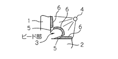
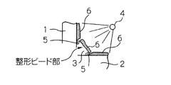
図6は、ウェブ材1及びフランジ材2の接合部に形成された溶接ビード3に吹き付け塗装装置4を用いて吹き付け塗装を行う状況を、模式的に示す説明図である。
FIG. 6 is an explanatory view schematically showing a state in which spray coating is performed on the
しかし、この溶接ビード3の近傍には、溶接により凸状に形成された溶接ビード3の高さや幅が吹き付け塗装の障害となって、吹き付け塗装装置4の吹き付け位置をどのように変更しても、必要な膜厚の塗膜6が形成されない塗装不良部5が不可避的に発生する。このような塗装不良部5は、早期に錆を発生する起点となる。
However, in the vicinity of the
また、溶接ビード3には、その高さや幅が長手方向へ周期的に変化するビード波が発生するとともに、その表面には凹凸も発生する。このような溶接ビード3の形状の長手方向への変動にも起因して、溶接ビード3には、吹き付け塗装の膜厚が目標値に達しなくなる箇所も生じる。
Further, the
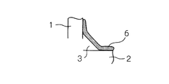
そこで、特許文献1には、溶接を行う圧接ロールの下流に、溶接ビードを圧潰して整形するためのビード整形ロールを配置しておき、このビード整形ロールを用いて、溶接直後の500 〜1200℃の赤熱状態にある溶接ビードを圧潰する発明が開示されている。図7は、この発明により圧潰された溶接ビード3の状況を示す説明図である。
Therefore, in
また、特許文献2には、ビード整形ロールを圧接ロールと同一線上に配置して、溶接ビードを整形する発明が開示されている。
しかし、これらの従来の発明によっても、溶接ビード3の近傍に形成される塗装不良部5を完全に解消することはできなかった。
However, even with these conventional inventions, the
例えば、特許文献1により開示された発明によれば、図7に示すように、塗装不良部5は縮小される。しかし、図8に示すように、塗装不良部5が完全に解消されて塗装不良部5がなくなるわけではない。このため、特許文献1により開示された発明によっても溶接ビード3の近傍における錆の発生を完全に解消できなかった。特許文献2により開示された発明によっても事情は同じである。
For example, according to the invention disclosed in
本発明の目的は、例えば溶接H形鋼等の溶接形鋼の品質を向上することができる溶接形鋼の製造方法を提供することである。 The objective of this invention is providing the manufacturing method of the welded shape steel which can improve the quality of welded shape steel, such as a welded H-section steel, for example.
本発明は、表面処理鋼帯からなるウェブ材及びフランジ材を所定の横断面形状となるように組み合わせて溶接する圧接工程、この溶接により形成された溶接ビードを整形するビード整形工程、及び整形されたビード形状をこの溶接ビードの長手方向について検査するビード形状検査工程をこの順で連続的に経た後に、整形された溶接ビード及びその近傍に吹き付け塗装を行うことによって溶接形鋼を製造する方法であって、整形された溶接ビード部の近傍に塗装不良が発生しない溶接ビードの整形後の目標形状を、前記整形後の溶接ビードの噛み出し量が0.5mm以下となる形状として予め定めておき、ビード形状検査工程による、溶接ビードの長手方向へのビード形状検査の結果を基に、溶接ビードの整形後の、溶接ビードの長手方向の各部の形状が目標形状となるように、ウェブ材及びフランジ材の長手方向の各部の溶接条件を調整することを特徴とする溶接形鋼の製造方法である。 The present invention relates to a pressure welding step for welding a web material and a flange material made of a surface-treated steel strip in combination so as to have a predetermined cross-sectional shape, a bead shaping step for shaping a weld bead formed by the welding, and a shaping process. In this method, the welded shape steel is manufactured by spraying the shaped bead and its vicinity after continuously performing the bead shape inspection process in this order for inspecting the bead shape in the longitudinal direction of the weld bead. The target shape after shaping of the weld bead that does not cause poor coating in the vicinity of the shaped weld bead portion is determined in advance as a shape in which the biting amount of the weld bead after shaping is 0.5 mm or less , by bead shape inspection process, based on the results of the bead shape inspection in the longitudinal direction of the weld bead, after shaping of the weld bead, the longitudinal direction of each portion of the weld bead As Jo becomes a target shape is a method for producing a welded shaped steel and adjusts the welding condition in the longitudinal direction of each portion of the web material and flange material.
この本発明に係る溶接形鋼の製造方法では、溶接条件が、溶接電流、溶接を行われる前のウェブ材に対するプリアプセット量又は溶接の際における溶接アプセット量のうちの1つ又は2つ以上の組合せであることが望ましい。 In the manufacturing method of weld shaped steel according to the present invention, welding conditions, welding current, one of the welding upset amount at the time of Apulian chipset amount or welded to the previous web material takes place welding or two or more it is desirable is a combination.
本発明により、例えば溶接H形鋼等の溶接形鋼の品質を向上することができる溶接形鋼の製造方法を提供することができた。 According to the present invention, for example, a method for producing a welded shape steel capable of improving the quality of a welded shape steel such as a welded H-shape steel can be provided.
以下、本発明に係る溶接形鋼の製造方法の実施の形態を、添付図面を参照しながら詳細に説明する。なお、以降の説明では、溶接形鋼が溶接H形鋼である場合を例にとるが、本発明は溶接H形鋼に限定されるものではなく、例えば溶接T形鋼等の溶接H形鋼以外の他の溶接形鋼についても同様に適用される。 Embodiments of a method for producing a welded steel according to the present invention will be described below in detail with reference to the accompanying drawings. In the following description, the case where the welded section steel is a welded H-section steel will be taken as an example. However, the present invention is not limited to the welded H-section steel. The same applies to other welded shape steels.
図1は、本実施の形態で用いる溶接H形鋼11の製造装置10の構成を模式的に示す説明図である。溶接H形鋼11は、溶融亜鉛めっき鋼帯などの表面処理鋼帯からなるウェブ材およびフランジ材を母材として、これらを横断面がH形となるように組み合わせて高周波溶接により溶接される。
FIG. 1 is an explanatory view schematically showing the configuration of a
同図に示すように、この製造装置10は、プリアプセット装置12、面取り装置13、給電装置14、圧接装置15、ビード整形装置16ならびに吹き付け塗装装置 (図示しない) を備えている。そこで、これらの構成要素について順次説明する。
As shown in the figure, the
(i)プリアプセット装置12
プリアプセット装置12は、例えば1対のフラットロール (又は孔型ロール)12aを1組または複数組 (図示例では2組) をタンデムに配置した構造である。プリアプセット装置12は、フランジ材11b との溶着幅を大きく確保するために、ウェブ材11a の端部を幅方向に押圧することにより、その端部11a'を膨らませるものである。この際、1対のフラットロール12a によるウェブ材11a の幅方向圧下量を「プリアプセット量」という。
(i) Pre-upset
The
(ii) 面取り装置13
面取り装置13は、例えば1対の孔型ロール13a により構成される。この1対の孔型ロール13a によりプリアプセットされたウェブ材11a の端部11a'を押圧することにより、端部11a'の面取りを行う。
(ii)
The
(iii)給電装置14
給電装置14は、給電子14a,14a と高周波電源 (図示しない) とから構成される。給電子14a,14a は、ウェブ材11a 及びフランジ材11b,11b にそれぞれ当接し、高周波電源からウェブ材11a 及びフランジ材11b,11b に高周波電流 (溶接電流) を通電することにより、ウェブ材11a 及びフランジ材11b,11b を1300〜1400℃程度に加熱した後、例えば、一対の太鼓状ロール14b,14b を備えた圧接装置によりウェブ材11a の端部をフランジ材11b,11b に圧接する。この際、圧接装置によるウェブ材11a の幅方向圧下量を「溶接アプセット量」という。
(iii)
The
(iv) ビード整形装置16
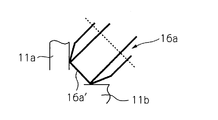
ビード整形装置16は、例えば、圧接により発生した溶接ビードを押圧して整形するために溶接ビードに対向して円弧状あるいは平坦状の整形部16a',16b' を備えたタイヤ状のロール16a,16b を備える。ロール16a,16b は、本実施の形態では溶接完了点から50〜200mm の位置に配置される。
(iv)
The
整形部16a',16b' の幅は、所定の溶接品質を得ることができるようにウェブ材11a の厚みに応じて、経験的に決定すればよい。
The widths of the shaping
このタイヤ状のロール16a,16b は、ウェブ材11a に対して接近及び離隔できるように移動自在に配置される。ロール16a,16b のロール軸は、ウェブ材11a に対して30〜60°の傾斜角度を有するように配置される。ロール16a,16b によるビード整形では、整形部16a',16b' の両縁部がウェブ材11a とフランジ材11b,11b とから適正距離離れた状態の所定の位置にロール16a,16b を固定配置することにより、圧接溶接により生じた溶接ビードをロール16a,16b の整形部16a',16b' により押圧し、整形することができる。
The tire-
図2は、ロール16a の先端部を拡大して示す説明図である。図2に示すように、整形部16a'の縁部とウェブ材11a との距離および整形部16a'の縁部とフランジ材11b との距離は、0.5 〜1.Omm とすることが望ましい。
FIG. 2 is an explanatory view showing the tip end portion of the
(v)吹き付け塗装装置 (図示しない)
吹き付け塗装装置 (図示しない) は、ビード整形装置16及び後述するビード検出装置の下流に配置され、例えば、樹脂に防錆顔料を添加した防錆塗料を整形後の溶接ビードに吹き付けるためのノズルを溶接ビードに対向して備える。このノズルから整形後の溶接ビードに塗料が吹き付けられ、溶接ビードを覆うように塗膜が形成される。
(v) Spray coating equipment (not shown)
The spray coating device (not shown) is disposed downstream of the
本実施の形態で用いる溶接H形鋼11の製造装置10は、以上のように構成される。次に、この製造装置10を用いて溶接H形鋼11を製造する状況を説明する。
The
本実施の形態では、プリアプセット装置12による端部11a'の膨出整形と、面取り装置13による端部11a'の面取りとを行われたウェブ材11a と、フランジ材11b,11b とをH形の横断面形状となるように組み合わせてから、給電装置14及び圧接装置15を用いて溶接し、溶接により形成された溶接ビードをビード整形装置16により整形した後に、整形された溶接ビード及びその近傍に吹き付け塗装を行うことによって溶接形鋼を製造する。
In the present embodiment, the
この際、本実施の形態では、整形された溶接ビードの近傍に塗装不良が発生しない溶接ビードの整形後の目標形状を予め定めておき、溶接ビードの整形後の形状が目標形状となるように、ウェブ材11a 及びフランジ材11b,11b の溶接条件を調整する。この理由を以下に説明する。
At this time, in the present embodiment, a target shape after shaping the weld bead that does not cause poor coating in the vicinity of the shaped weld bead is determined in advance, and the shape after shaping the weld bead becomes the target shape. Then, the welding conditions of the
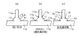
図3(a) 〜図3(c) は、整形された溶接ビード17の形状例を示す説明図である。
FIG. 3A to FIG. 3C are explanatory views showing an example of the shape of the shaped
図3(b) に示すように、高周波溶接により生じる溶接ビード17をビード整形装置16を用いて押圧整形し、押圧整形された後の溶接ビード17の幅がロール16a,16b の整形部16a',16b' の幅w より大きいと、溶接ビード17の噛み出し部17a が生じる。この噛み出し部17a の量が過大であると塗料の吹き付けが不十分となり、錆が発生し易い。
As shown in FIG. 3 (b), a
また、図3(c) に示すように、ビード整形装置16を用いて押圧整形された後の溶接ビード17の幅がロール16a,16b の幅w より小さいと、溶接ビード17とウェブ11a との間、溶接ビード17とフランジ11b との間に隙間18が生じる。この隙間18の幅 (フランジ又はウェブ延設方向距離) が過大、例えば隙間18が0.2mm 超になると隙間18への塗料の吹き付けが不十分となり、錆が発生し易い。
Further, as shown in FIG. 3 (c), if the width of the
これに対し、図3(a) に示すように、溶接ビード17の隙間が0.2mm 以下であれば、吹き付けにより溶接ビード17を塗料で完全に覆うことが可能となり、錆の発生を防止できる。また、片側の噛み出し量が0.5mm 以下であれば、上述した図8に示すように、吹き付けにより溶接ビード17を塗料で覆うことが可能となり、溶接ビード17の近傍からの錆の発生を防止できる。
On the other hand, as shown in FIG. 3A, if the gap between the
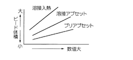
図4は、溶接入熱、溶接アプセット量又はプリアプセット量の値が、形成される溶接ビードの体積に及ぼす影響を調べた結果を示すグラフである。同図にグラフで示すように、溶接ビードの噛み出し量やビードの隙間は、溶接条件、例えば溶接入熱 (溶接出力) 、溶接アプセット量又はプリアプセット量の一つ以上を変更することによって変化させることができる。 FIG. 4 is a graph showing the results of examining the influence of welding heat input, welding upset amount or pre-upset amount on the volume of the weld bead to be formed. As shown in the graph, the welding bead biting amount and bead gap change by changing one or more of the welding conditions, such as welding heat input (welding output), welding upset amount, or pre-upset amount. Can be made.
このため、溶接ビードの噛み出し量や溶接ビードの隙間が適正な範囲となって溶接ビードの塗装不良を発生しないように、溶接入熱、溶接アプセット量又はプリアプセット量の一つ以上からなる溶接条件を調整することによって、溶接ビードを塗膜で効果的に覆うことが可能となり、これにより、溶接ビードの近傍からの錆の発生を解消することができる。 For this reason, welding consisting of at least one of welding heat input, welding upset amount or pre-upset amount so that the welding bead biting amount and the weld bead gap are in an appropriate range and coating defects of the weld bead do not occur. By adjusting the conditions, it becomes possible to effectively cover the weld bead with the coating film, thereby eliminating the occurrence of rust from the vicinity of the weld bead.
以上の理由により、本実施の形態では、整形された溶接ビードの近傍に塗装不良が発生しない溶接ビードの整形後の目標形状を予め定めておき、溶接ビードの整形後の形状が目標形状となるように、ウェブ材11a 及びフランジ材11b,11b の溶接条件を調整する。
For the above reasons, in the present embodiment, a target shape after shaping of a weld bead that does not cause poor coating in the vicinity of the shaped weld bead is determined in advance, and the shape after shaping of the weld bead becomes the target shape. In this manner, the welding conditions of the
例えば、目標形状は、図5に示すように、整形後の溶接ビードの噛み出し量が片側で0.5mm 以下で、かつ、溶接ビードの隙間を0.2mm 以内とする。そして、整形後の溶接ビード形状が目標値となるように溶接条件を微調整して、溶接形鋼11を製造する。本実施の形態では、溶接条件として溶接出力を微調整した。
For example, as shown in FIG. 5, the target shape is such that the amount of biting of the weld bead after shaping is 0.5 mm or less on one side and the gap of the weld bead is within 0.2 mm. Then, the welded
整形後の溶接ビードの形状が目標値となるか否かは、目視やカメラ等のビード検出装置を用いた観察が可能である。溶接ビードの隙間が過大である場合には、溶接電流を大きく設定するか、又はプリアプセット量や溶接アプセット量を大きく設定すればよい。これとは異なり、噛み出し量が過大である場合には、溶接電流を小さく設定するか、又はプリアプセット量や溶接アプセット量を小さく設定すればよい。 Whether or not the shape of the weld bead after shaping becomes a target value can be observed visually or using a bead detection device such as a camera. When the gap of the weld bead is excessive, the welding current may be set large, or the pre-upset amount and the welding upset amount may be set large. In contrast to this, when the amount of biting is excessive, the welding current may be set small, or the pre-upset amount and the welding upset amount may be set small.
なお、溶接電流、プリアプセット量又は溶接のアプセット量の設定値の変更は、整形後の溶接ビードの形状の測定結果に基づいて、自動で行うようにしてもよいし、手動で行うようにしてもよい。 The setting value of the welding current, pre-upset amount or welding upset amount may be changed automatically based on the measurement result of the shape of the weld bead after shaping, or manually. Also good.
このように、本実施の形態によれば、塗装される時点における溶接ビードは塗装不良を生じない形状になっているので、塗装不良部がなくなり、溶接ビードの近傍における錆の発生を完全に解消できる。これにより、溶接H形鋼の品質を向上することができる。 As described above, according to the present embodiment, the weld bead at the time of painting has a shape that does not cause poor coating, so there is no defective coating, and rust generation near the weld bead is completely eliminated. it can. Thereby, the quality of the welded H-section steel can be improved.
さらに、本発明を実施例を参照しながら詳細に説明する。 Further, the present invention will be described in detail with reference to examples.
図1に示す製造装置10を用いて、以下に列記する条件及び方法で溶接H形鋼を製造した。
Using the
A. 条件
(1)表面処理鋼帯:Z27(JIS G 3302の非合金等厚めっき付着量の表示記号) の溶 融亜鉛めっき鋼板
ウェブ材11b の厚:3.2mm 、フランジ材11a の厚:4.5mm
(2)製品11の寸法: 200×100 ×3.2/4.5(mm)
(3)プリアプセット装置12:フラットロール、プリアプセット量2mm (両側)
(4)面取り装置13:孔型ロール
(5)高周波電源:周波数360kHz、加熱温度:約1300℃、溶接電流 (1次側):30A(基準)
(6)給電子14a :ウェブ材とフランジ材の双方に当接
(7)圧接装置15:太鼓型ロール14b の溶接アプセット量4mm (両側)
(8)ビード整形装置16:図1に示す平坦状の整形部16a'を備えたロール16a
平坦状部の幅4mm
(9)吹き付け塗装装置:エアースプレー方式、塗料:エポキシ樹脂に防錆顔料と してりん酸アルミニウムを添加したもの。
A. Conditions
(1) Surface-treated steel strip: Hot-dip galvanized steel sheet of Z27 (JIS G 3302 non-alloy iso-thick plating coating symbol)
(2)
(3) Pre-upset device 12: flat roll, pre-upset amount 2mm (both sides)
(4) Chamfering device 13: Hole type roll
(5) High frequency power supply: frequency 360kHz, heating temperature: about 1300 ℃, welding current (primary side): 30A (standard)
(6) Feeder 14a: Abuts on both web and flange material
(7) Pressure welding device 15: 4mm welding upset amount of
(8) Bead shaping device 16: roll 16a provided with a
Flat part width 4mm
(9) Spray coating equipment: Air spray system, Paint: Aluminum resin added with rust preventive pigment to epoxy resin.
B. 方法
プリアプセット加工と面取り加工を施したウェブ材11a とフランジ材11b 、11b と突き合わせ、給電子14a 、14a を両部材に当接して通電することにより約1300℃に加熱し、圧接ロール14b 、14b で圧接を行う。その後、整形部の縁部とウェブ材との距離および縁部とフランジ材との距離を0.5 〜1.Omm の範囲の位置に固定配置されたビード整形ロール16a 、16b を用いて、溶接ビードを押圧して整形する。その後、整形された溶接ビードに上記塗料の吹き付け塗装を行い、溶接H形鋼を得る。その際、目視にて整形された溶接ビードの形状を観察し、片側の噛み出し量が0.5mm 以下の形状となるように溶接電流を調節した。
B. Method The
このようにして得られた溶接H形鋼に以下の防錆耐久試験を行い、防錆性能を評価した。 The welded H-shaped steel thus obtained was subjected to the following antirust durability test to evaluate the antirust performance.
(防錆耐久試験:JASO M609(ISO 14993))
塩水噴霧試験(2時間) →乾燥 (60℃×4時間) →湿潤 (98%湿度×50℃×2 時間) を1サイクルとし、赤錆発生までのサイクル数を求める試験
この結果、溶接ビードは、エポキシ樹脂により完全に覆われており、防錆耐久試験でも、塗装膜厚20μmの塗装でビード部は溶融亜鉛めっき鋼板とほぼ同等の防錆性能を示した。
(Anti-rust durability test: JASO M609 (ISO 14993))
Salt water spray test (2 hours) → Drying (60 ° C x 4 hours) → Wet (98% humidity x 50 ° C x 2 hours) is one cycle, and the number of cycles until red rust occurs. It was completely covered with epoxy resin, and in the rust prevention durability test, the bead portion showed almost the same rust prevention performance as the hot-dip galvanized steel sheet with a coating thickness of 20 μm.
このように、本実施例によれば、塗装不良部がなくなり、溶接ビードの近傍における錆の発生を完全に解消できた。これにより、溶接H形鋼の品質を向上することができた。 Thus, according to the present Example, the coating defect part was lost and generation | occurrence | production of the rust in the vicinity of the weld bead was completely eliminated. Thereby, the quality of welded H-section steel was able to be improved.
10 製造装置
11 溶接H形鋼
11a ウェブ材
11a' 端部
11b フランジ材
12 プリアプセット装置
12a フラットロール (又は孔型ロール)
13 面取り装置
13a 孔型ロール
14 給電装置
14a,14a 給電子
14b,14b 太鼓状ロール
15 圧接装置
16 ビード整形装置
16a,16b ロール
16a',16b' 整形部
10 Production equipment
11 Welded H-section steel
11a Web material
11a 'end
11b Flange material
12 Pre-upset device
12a Flat roll (or perforated roll)
13 Chamfering device
13a Perforated roll
14 Power supply device
14a, 14a
14b, 14b drum roll
15 Pressure welding device
16 Bead shaping device
16a, 16b roll
16a ', 16b' shaping part
Claims (2)
整形された前記溶接ビード部の近傍に塗装不良が発生しない溶接ビードの整形後の目標形状を、前記整形後の溶接ビードの噛み出し量が0.5mm以下となる形状として予め定めておき、前記ビード形状検査工程による前記長手方向へのビード形状検査の結果を基に、該溶接ビードの整形後の前記長手方向の各部の形状が該目標形状となるように、前記ウェブ材及びフランジ材の長手方向の各部の溶接条件を調整すること
を特徴とする溶接形鋼の製造方法。 A pressure welding step of combining and welding a web material and a flange material made of a surface-treated steel strip so as to have a predetermined cross-sectional shape, a bead shaping step for shaping a weld bead formed by this welding, and a shaped bead shape A method for producing a welded shape steel by spraying a weld bead that has been shaped after passing through a bead shape inspecting step in this order continuously for the longitudinal direction of the weld bead and the vicinity thereof,
The target shape after shaping of the weld bead that does not cause poor coating in the vicinity of the shaped weld bead portion is determined in advance as a shape in which the bite amount of the weld bead after shaping is 0.5 mm or less, and the bead based on the results of the bead shape inspection to the longitudinal direction due to the shape inspection process, so that the longitudinal direction of each portion of the shape of the shaped of the weld bead becomes the target shape, the longitudinal direction of the web material and the flange member A method for producing a welded shape steel, comprising adjusting welding conditions for each part of the welded steel.
Priority Applications (1)
| Application Number | Priority Date | Filing Date | Title |
|---|---|---|---|
| JP2003272934A JP4457595B2 (en) | 2003-07-10 | 2003-07-10 | Manufacturing method of welded section steel |
Applications Claiming Priority (1)
| Application Number | Priority Date | Filing Date | Title |
|---|---|---|---|
| JP2003272934A JP4457595B2 (en) | 2003-07-10 | 2003-07-10 | Manufacturing method of welded section steel |
Publications (2)
| Publication Number | Publication Date |
|---|---|
| JP2005028434A JP2005028434A (en) | 2005-02-03 |
| JP4457595B2 true JP4457595B2 (en) | 2010-04-28 |
Family
ID=34210337
Family Applications (1)
| Application Number | Title | Priority Date | Filing Date |
|---|---|---|---|
| JP2003272934A Expired - Fee Related JP4457595B2 (en) | 2003-07-10 | 2003-07-10 | Manufacturing method of welded section steel |
Country Status (1)
| Country | Link |
|---|---|
| JP (1) | JP4457595B2 (en) |
-
2003
- 2003-07-10 JP JP2003272934A patent/JP4457595B2/en not_active Expired - Fee Related
Also Published As
| Publication number | Publication date |
|---|---|
| JP2005028434A (en) | 2005-02-03 |
Similar Documents
| Publication | Publication Date | Title |
|---|---|---|
| JPWO2018087818A1 (en) | Welding monitoring apparatus and welding monitoring method | |
| US6288361B1 (en) | Method and device for joining flat products to be connected such that they overlap | |
| JP4457595B2 (en) | Manufacturing method of welded section steel | |
| KR102024415B1 (en) | Laser-welded shaped steel | |
| JP5656220B2 (en) | Manufacturing method of laser welded H-section steel | |
| KR890003098B1 (en) | Manufacturing method of welding pipe body | |
| CN110142310A (en) | A kind of production technology of steel pipes with straight | |
| CN101903595A (en) | Process for the manufacture of metal strips for use in paper/board machines or finishing machines | |
| JP4483215B2 (en) | Manufacturing method of welded section steel | |
| KR101934586B1 (en) | pipe bead pressure apparatus | |
| JP5082746B2 (en) | Manufacturing equipment and manufacturing method of square steel pipe | |
| JP2000271639A (en) | Plated steel tube and its manufacture | |
| KR100293577B1 (en) | Method of and apparatus for producing steel pipes | |
| WO2021065067A1 (en) | Welding method, plate-shaped member, and elevator equipment | |
| JP5312735B2 (en) | ERW pipe manufacturing method with good weld characteristics | |
| JP3682682B2 (en) | Manufacturing method of thin wall forged pipe | |
| KR100859582B1 (en) | Thermal spraying guide and thermal spray removal device of galvanized steel pipe | |
| JP4586515B2 (en) | Welded steel pipe with secondary workability comparable to that of the base metal in the welded part and method for producing the same | |
| JPH04200907A (en) | Hot joining method for steel material | |
| JP3327842B2 (en) | Prevention of fracture near the weld in continuous rolling | |
| JPS6030589A (en) | Production of welded can body | |
| KR20240164123A (en) | Performance Evaluation Method for Laser Welded Joints | |
| JPS617079A (en) | Production of welded can body | |
| JPH07314047A (en) | Method of manufacturing square steel pipe | |
| JPH07265942A (en) | Welding method of ERW steel pipe |
Legal Events
| Date | Code | Title | Description |
|---|---|---|---|
| A621 | Written request for application examination |
Free format text: JAPANESE INTERMEDIATE CODE: A621 Effective date: 20050720 |
|
| A131 | Notification of reasons for refusal |
Free format text: JAPANESE INTERMEDIATE CODE: A131 Effective date: 20081007 |
|
| A521 | Written amendment |
Free format text: JAPANESE INTERMEDIATE CODE: A523 Effective date: 20081201 |
|
| A131 | Notification of reasons for refusal |
Free format text: JAPANESE INTERMEDIATE CODE: A131 Effective date: 20091013 |
|
| A521 | Written amendment |
Free format text: JAPANESE INTERMEDIATE CODE: A523 Effective date: 20091211 |
|
| TRDD | Decision of grant or rejection written | ||
| A01 | Written decision to grant a patent or to grant a registration (utility model) |
Free format text: JAPANESE INTERMEDIATE CODE: A01 Effective date: 20100119 |
|
| A01 | Written decision to grant a patent or to grant a registration (utility model) |
Free format text: JAPANESE INTERMEDIATE CODE: A01 |
|
| A61 | First payment of annual fees (during grant procedure) |
Free format text: JAPANESE INTERMEDIATE CODE: A61 Effective date: 20100201 |
|
| R150 | Certificate of patent or registration of utility model |
Free format text: JAPANESE INTERMEDIATE CODE: R150 Ref document number: 4457595 Country of ref document: JP Free format text: JAPANESE INTERMEDIATE CODE: R150 |
|
| FPAY | Renewal fee payment (event date is renewal date of database) |
Free format text: PAYMENT UNTIL: 20130219 Year of fee payment: 3 |
|
| FPAY | Renewal fee payment (event date is renewal date of database) |
Free format text: PAYMENT UNTIL: 20130219 Year of fee payment: 3 |
|
| S111 | Request for change of ownership or part of ownership |
Free format text: JAPANESE INTERMEDIATE CODE: R313111 |
|
| FPAY | Renewal fee payment (event date is renewal date of database) |
Free format text: PAYMENT UNTIL: 20130219 Year of fee payment: 3 |
|
| R350 | Written notification of registration of transfer |
Free format text: JAPANESE INTERMEDIATE CODE: R350 |
|
| FPAY | Renewal fee payment (event date is renewal date of database) |
Free format text: PAYMENT UNTIL: 20140219 Year of fee payment: 4 |
|
| S533 | Written request for registration of change of name |
Free format text: JAPANESE INTERMEDIATE CODE: R313533 |
|
| R350 | Written notification of registration of transfer |
Free format text: JAPANESE INTERMEDIATE CODE: R350 |
|
| LAPS | Cancellation because of no payment of annual fees |