JP4457559B2 - Fuel evaporator - Google Patents
Fuel evaporator Download PDFInfo
- Publication number
- JP4457559B2 JP4457559B2 JP2003003594A JP2003003594A JP4457559B2 JP 4457559 B2 JP4457559 B2 JP 4457559B2 JP 2003003594 A JP2003003594 A JP 2003003594A JP 2003003594 A JP2003003594 A JP 2003003594A JP 4457559 B2 JP4457559 B2 JP 4457559B2
- Authority
- JP
- Japan
- Prior art keywords
- fuel
- reformer
- air
- evaporation apparatus
- supplied
- Prior art date
- Legal status (The legal status is an assumption and is not a legal conclusion. Google has not performed a legal analysis and makes no representation as to the accuracy of the status listed.)
- Expired - Lifetime
Links
Images

Classifications
-
- B—PERFORMING OPERATIONS; TRANSPORTING
- B01—PHYSICAL OR CHEMICAL PROCESSES OR APPARATUS IN GENERAL
- B01J—CHEMICAL OR PHYSICAL PROCESSES, e.g. CATALYSIS OR COLLOID CHEMISTRY; THEIR RELEVANT APPARATUS
- B01J19/00—Chemical, physical or physico-chemical processes in general; Their relevant apparatus
- B01J19/0006—Controlling or regulating processes
- B01J19/0013—Controlling the temperature of the process
-
- B—PERFORMING OPERATIONS; TRANSPORTING
- B01—PHYSICAL OR CHEMICAL PROCESSES OR APPARATUS IN GENERAL
- B01B—BOILING; BOILING APPARATUS ; EVAPORATION; EVAPORATION APPARATUS
- B01B1/00—Boiling; Boiling apparatus for physical or chemical purposes ; Evaporation in general
- B01B1/005—Evaporation for physical or chemical purposes; Evaporation apparatus therefor, e.g. evaporation of liquids for gas phase reactions
-
- C—CHEMISTRY; METALLURGY
- C01—INORGANIC CHEMISTRY
- C01B—NON-METALLIC ELEMENTS; COMPOUNDS THEREOF; METALLOIDS OR COMPOUNDS THEREOF NOT COVERED BY SUBCLASS C01C
- C01B3/00—Hydrogen; Gaseous mixtures containing hydrogen; Separation of hydrogen from mixtures containing it; Purification of hydrogen; Reversible storage of hydrogen
- C01B3/02—Production of hydrogen; Production of gaseous mixtures containing hydrogen
- C01B3/32—Production of hydrogen; Production of gaseous mixtures containing hydrogen by reaction of gaseous or liquid organic compounds with gasifying agents, e.g. water, carbon dioxide or air
- C01B3/34—Production of hydrogen; Production of gaseous mixtures containing hydrogen by reaction of gaseous or liquid organic compounds with gasifying agents, e.g. water, carbon dioxide or air by reaction of hydrocarbons with gasifying agents
- C01B3/38—Production of hydrogen; Production of gaseous mixtures containing hydrogen by reaction of gaseous or liquid organic compounds with gasifying agents, e.g. water, carbon dioxide or air by reaction of hydrocarbons with gasifying agents using catalysts
- C01B3/382—Processes with two or more reaction steps, of which at least one is catalytic, e.g. steam reforming and partial oxidation
-
- B—PERFORMING OPERATIONS; TRANSPORTING
- B01—PHYSICAL OR CHEMICAL PROCESSES OR APPARATUS IN GENERAL
- B01J—CHEMICAL OR PHYSICAL PROCESSES, e.g. CATALYSIS OR COLLOID CHEMISTRY; THEIR RELEVANT APPARATUS
- B01J2208/00—Processes carried out in the presence of solid particles; Reactors therefor
- B01J2208/00008—Controlling the process
- B01J2208/00716—Means for reactor start-up
-
- B—PERFORMING OPERATIONS; TRANSPORTING
- B01—PHYSICAL OR CHEMICAL PROCESSES OR APPARATUS IN GENERAL
- B01J—CHEMICAL OR PHYSICAL PROCESSES, e.g. CATALYSIS OR COLLOID CHEMISTRY; THEIR RELEVANT APPARATUS
- B01J2219/00—Chemical, physical or physico-chemical processes in general; Their relevant apparatus
- B01J2219/00049—Controlling or regulating processes
- B01J2219/00051—Controlling the temperature
- B01J2219/00054—Controlling or regulating the heat exchange system
- B01J2219/00056—Controlling or regulating the heat exchange system involving measured parameters
- B01J2219/00058—Temperature measurement
- B01J2219/00063—Temperature measurement of the reactants
-
- B—PERFORMING OPERATIONS; TRANSPORTING
- B01—PHYSICAL OR CHEMICAL PROCESSES OR APPARATUS IN GENERAL
- B01J—CHEMICAL OR PHYSICAL PROCESSES, e.g. CATALYSIS OR COLLOID CHEMISTRY; THEIR RELEVANT APPARATUS
- B01J2219/00—Chemical, physical or physico-chemical processes in general; Their relevant apparatus
- B01J2219/00049—Controlling or regulating processes
- B01J2219/00051—Controlling the temperature
- B01J2219/00132—Controlling the temperature using electric heating or cooling elements
-
- C—CHEMISTRY; METALLURGY
- C01—INORGANIC CHEMISTRY
- C01B—NON-METALLIC ELEMENTS; COMPOUNDS THEREOF; METALLOIDS OR COMPOUNDS THEREOF NOT COVERED BY SUBCLASS C01C
- C01B2203/00—Integrated processes for the production of hydrogen or synthesis gas
- C01B2203/02—Processes for making hydrogen or synthesis gas
- C01B2203/0205—Processes for making hydrogen or synthesis gas containing a reforming step
- C01B2203/0227—Processes for making hydrogen or synthesis gas containing a reforming step containing a catalytic reforming step
- C01B2203/0244—Processes for making hydrogen or synthesis gas containing a reforming step containing a catalytic reforming step the reforming step being an autothermal reforming step, e.g. secondary reforming processes
-
- C—CHEMISTRY; METALLURGY
- C01—INORGANIC CHEMISTRY
- C01B—NON-METALLIC ELEMENTS; COMPOUNDS THEREOF; METALLOIDS OR COMPOUNDS THEREOF NOT COVERED BY SUBCLASS C01C
- C01B2203/00—Integrated processes for the production of hydrogen or synthesis gas
- C01B2203/04—Integrated processes for the production of hydrogen or synthesis gas containing a purification step for the hydrogen or the synthesis gas
- C01B2203/0435—Catalytic purification
- C01B2203/044—Selective oxidation of carbon monoxide
-
- C—CHEMISTRY; METALLURGY
- C01—INORGANIC CHEMISTRY
- C01B—NON-METALLIC ELEMENTS; COMPOUNDS THEREOF; METALLOIDS OR COMPOUNDS THEREOF NOT COVERED BY SUBCLASS C01C
- C01B2203/00—Integrated processes for the production of hydrogen or synthesis gas
- C01B2203/04—Integrated processes for the production of hydrogen or synthesis gas containing a purification step for the hydrogen or the synthesis gas
- C01B2203/0465—Composition of the impurity
- C01B2203/047—Composition of the impurity the impurity being carbon monoxide
-
- C—CHEMISTRY; METALLURGY
- C01—INORGANIC CHEMISTRY
- C01B—NON-METALLIC ELEMENTS; COMPOUNDS THEREOF; METALLOIDS OR COMPOUNDS THEREOF NOT COVERED BY SUBCLASS C01C
- C01B2203/00—Integrated processes for the production of hydrogen or synthesis gas
- C01B2203/06—Integration with other chemical processes
- C01B2203/066—Integration with other chemical processes with fuel cells
-
- C—CHEMISTRY; METALLURGY
- C01—INORGANIC CHEMISTRY
- C01B—NON-METALLIC ELEMENTS; COMPOUNDS THEREOF; METALLOIDS OR COMPOUNDS THEREOF NOT COVERED BY SUBCLASS C01C
- C01B2203/00—Integrated processes for the production of hydrogen or synthesis gas
- C01B2203/08—Methods of heating or cooling
- C01B2203/0805—Methods of heating the process for making hydrogen or synthesis gas
- C01B2203/0838—Methods of heating the process for making hydrogen or synthesis gas by heat exchange with exothermic reactions, other than by combustion of fuel
- C01B2203/0844—Methods of heating the process for making hydrogen or synthesis gas by heat exchange with exothermic reactions, other than by combustion of fuel the non-combustive exothermic reaction being another reforming reaction as defined in groups C01B2203/02 - C01B2203/0294
-
- C—CHEMISTRY; METALLURGY
- C01—INORGANIC CHEMISTRY
- C01B—NON-METALLIC ELEMENTS; COMPOUNDS THEREOF; METALLOIDS OR COMPOUNDS THEREOF NOT COVERED BY SUBCLASS C01C
- C01B2203/00—Integrated processes for the production of hydrogen or synthesis gas
- C01B2203/12—Feeding the process for making hydrogen or synthesis gas
- C01B2203/1288—Evaporation of one or more of the different feed components
-
- C—CHEMISTRY; METALLURGY
- C01—INORGANIC CHEMISTRY
- C01B—NON-METALLIC ELEMENTS; COMPOUNDS THEREOF; METALLOIDS OR COMPOUNDS THEREOF NOT COVERED BY SUBCLASS C01C
- C01B2203/00—Integrated processes for the production of hydrogen or synthesis gas
- C01B2203/14—Details of the flowsheet
- C01B2203/142—At least two reforming, decomposition or partial oxidation steps in series
-
- C—CHEMISTRY; METALLURGY
- C01—INORGANIC CHEMISTRY
- C01B—NON-METALLIC ELEMENTS; COMPOUNDS THEREOF; METALLOIDS OR COMPOUNDS THEREOF NOT COVERED BY SUBCLASS C01C
- C01B2203/00—Integrated processes for the production of hydrogen or synthesis gas
- C01B2203/16—Controlling the process
- C01B2203/1604—Starting up the process
-
- C—CHEMISTRY; METALLURGY
- C01—INORGANIC CHEMISTRY
- C01B—NON-METALLIC ELEMENTS; COMPOUNDS THEREOF; METALLOIDS OR COMPOUNDS THEREOF NOT COVERED BY SUBCLASS C01C
- C01B2203/00—Integrated processes for the production of hydrogen or synthesis gas
- C01B2203/16—Controlling the process
- C01B2203/1614—Controlling the temperature
- C01B2203/1619—Measuring the temperature
-
- C—CHEMISTRY; METALLURGY
- C01—INORGANIC CHEMISTRY
- C01B—NON-METALLIC ELEMENTS; COMPOUNDS THEREOF; METALLOIDS OR COMPOUNDS THEREOF NOT COVERED BY SUBCLASS C01C
- C01B2203/00—Integrated processes for the production of hydrogen or synthesis gas
- C01B2203/80—Aspect of integrated processes for the production of hydrogen or synthesis gas not covered by groups C01B2203/02 - C01B2203/1695
- C01B2203/82—Several process steps of C01B2203/02 - C01B2203/08 integrated into a single apparatus
Landscapes
- Chemical & Material Sciences (AREA)
- Chemical Kinetics & Catalysis (AREA)
- Organic Chemistry (AREA)
- Health & Medical Sciences (AREA)
- General Health & Medical Sciences (AREA)
- Engineering & Computer Science (AREA)
- Combustion & Propulsion (AREA)
- Inorganic Chemistry (AREA)
- Hydrogen, Water And Hydrids (AREA)
- Feeding And Controlling Fuel (AREA)
- Fuel Cell (AREA)
- Spray-Type Burners (AREA)
Description
【0001】
【発明の属する技術分野】
本発明は、燃料蒸発装置、特に燃料改質器に燃料蒸気を供給する燃料蒸発装置に関するものである。
【0002】
【従来の技術】
従来の燃料改質装置に関する技術として、燃料改質器から排出される改質ガスの一部を燃焼器に供給し、供給される改質ガス量を所定量と比較、または改質ガス温を所定温度と比較する技術がある(例えば、特許文献1参照。)。
【0003】
また、燃料電池の出力要求値に応じて蒸発器に投入する原料投入量目標値を算出する原料投入量算出手段と、前記蒸発器における熱量の収支を推定する熱量収支推定手段と、前記熱量収支推定手段の推定した前記蒸発器における熱量の収支に基づいて、前記燃焼器を制御する燃焼器制御手段を備えた燃料改質器の制御装置に関する技術がある(例えば、特許文献2参照。)。
【0004】
また、改質器に燃料ガスを供給する燃焼器に関する技術として、燃焼器の燃焼触媒を酸素含有ガスを加熱するための加熱部と、加熱部の下流側に接続された燃焼触媒部とから構成する技術がある(例えば、特許文献3参照。)。
【0005】
また、燃料改質装置であって、改質触媒部が配置される改質室と、燃焼室で燃焼したガスを改質触媒部に供給する始動用燃焼室と備え、始動用燃焼機構は、燃焼室に加熱用燃料を供給する燃料噴射手段と、燃焼室に供給された加熱用燃料を着火させる着火用プラグとを備えることを特徴とする技術がある(例えば、特許文献4参照。)。
【0006】
燃料改質装置であって、内部に改質触媒層を備える第1の部屋と、第1の部屋に隣接して配置され、第1の部屋に冷却媒体を導入する第2の部屋とを有することを特徴とする技術がある(例えば、特許文献5参照。)。
【0007】
炭化水素系燃料を液相と気相の状態で水蒸気を添加して改質反応器に導入し、250℃以上の改質触媒により、250℃〜900℃に予熱された一酸化炭素、水素、二酸化炭素に富んだ改質ガスを改質反応器から排出して加熱器に供給する技術がある(例えば、特許文献6参照。)。
【0008】
他の改質装置であって、改質触媒が充填され且つ上下方向に向けて配置された反応管の外壁面に沿って加熱室を形成するとともに、加熱室の下方位置に燃焼器を備えたことを特徴とする技術がある(例えば、特許文献7参照。)。
【0009】
燃料改質システムであって、バーナの過剰加熱により改質部の構造材料が熱応力破壊されることを防ぐことを目的として、燃料を気化させる気化部及び気化された燃料を改質させて水素リッチガスを生成する改質器と、改質器の気化部及び改質部へそれぞれ送られる熱源ガスを生成する燃焼器とを備え、燃焼器は、冷却水を噴霧する冷却手段を備えることを特徴とする技術がある(例えば、特許文献8参照。)。
【0010】
改質器用燃焼器であって、改質部の過熱を防止し、改質触媒内の温度分布に差異が生じることを防止し、さらに改質器の構成材料の選択範囲を広げることを目的に、熱源発生部の発生する熱量を制御して一定量の熱量の熱源ガスに変換する熱源ガス変換部を有し、熱源ガス変換部が▲1▼熱源発生部を取り巻くように耐火性蓄熱材により形成され、▲2▼その内部に熱源発生部から発生する排ガスを通過させる排ガス抜口と、熱媒体を通過させ熱交換を行わせる熱媒体流路とを有し、▲3▼且つ、排ガスと熱媒体が合流してなる熱源ガスを排出する熱源ガス排出口とを有する技術がある(例えば、特許文献9参照。)。
【0011】
【特許文献1】
特開2001‐223016号公報
【特許文献2】
特開2001‐210347号公報
【特許文献3】
特開2001‐27403号公報
【特許文献4】
特開2000‐63104号公報
【特許文献5】
特開平8‐189380号公報
【特許文献6】
特開平8‐188784号公報
【特許文献7】
特開平8−2901号公報
【0012】
【特許文献8】
特開平7−172802号公報
【0013】
【特許文献9】
特開平7−103090号公報
【0014】
【発明が解決しようとする課題】
従来の技術では、改質器で改質反応を行わせるためにガソリンやメタノール等の炭化水素系燃料からなる燃料および水を改質触媒に供給する前に気化しておく必要があるが、蒸発した燃料が即時に気層で部分酸化され、H2Oと燃料の反応である水蒸気改質のような速度の遅い反応が期待できない。このため、改質により得られる水素の生成効率である改質効率が低いという課題がある。
【0015】
改質効率が低い理由をガソリン等炭化水素系燃料に多く含まれるオクタン(C8H18)で説明する。
【0016】
まず、各改質反応の反応式は以下のように表される。
部分酸化反応 C8H18+(8/2)O2→8CO+9H2+ΔQ (1)
水蒸気改質反応 C8H18+8H2O→8CO+17H2−ΔQ (2)
上式より、水蒸気改質反応は部分酸化反応に比べ、同じオクタン1モルから生成するH2の量がおよそ1.9倍であることがわかる。ここで、部分酸化反応は発熱反応であり、水蒸気改質反応は吸熱反応である。
【0017】
特許文献8に記載のようなバーナー方式の改質が、部分酸化により高温になる原因は、式(1)が発熱反応によるためである。式(2)の混合比で、1atm、25℃のオクタンと酸素を含む空気が部分酸化した場合、断熱界温度は694.2℃となり、この時には燃料は水蒸気改質反応があまり進行しないうちに既に部分酸化反応により改質されていることになる。
【0018】
一方、2つの改質反応の反応速度を比較すると、これは平衡論的には論じられないが、一般的に部分酸化反応が水蒸気改質反応より速い。このことは、高温水蒸気存在化においても、部分酸化反応は気層で生じるが、水蒸気改質反応は必ず触媒による活性化が必要とされることからも明らかである。
【0019】
以上のことから、燃料を気化−着火した700℃以上の火炎により、気層で改質を行っている改質器の場合、とりわけ特許文献8に記載のような気層バーナー部で部分酸化を起こすタイプの改質方式では、改質方式は部分酸化とならざるを得ず、水蒸気改質反応のような改質効率の高い改質方式を望むことができない。また、気層改質方式の自己起動を考えた場合、改質が始まるまでの間は未燃燃料が排出され、環境を悪化することが考えられる。
【0020】
一般的に冷間時の触媒は、活性化する前に燃料蒸気や燃料蒸気に含まれるCOに触れると、それらが触媒表面に吸着し、触媒反応の開始温度を引き上げることが知られる。特許文献3に記載の技術は、この課題を解決するために燃焼器において、より高温のガスを速やかに発生し、加熱すべき触媒に供給するものである。この技術では、燃料気化前の空気、燃料を加熱した後、この気体の熱により触媒が加熱されるため、前述の触媒表面への燃料付着による活性化の遅延を完全に回避することはできない。
【0021】
またここで、特許文献3に記載のような気層燃焼式バーナーを下式のような完全燃焼でCO等が存在しないクリーンな高温ガス発生器として用いることを考える。
完全酸化 C8H18+(25/2)O2→8CO2+9H2O+ΔQ (3)
この場合、1atm、25℃の状態からの燃焼と仮定すると、断熱界温度は、1884℃となり、通常の改質器構成部材の耐熱温度を越えてしまう。対策として、燃焼用空気の量を理論完全燃焼量の3倍(空気過剰率λ=3)とすると、加えられた空気の熱容量により、反応場の断熱界温度は887℃となり、材料の耐熱性は解決できる。但し、実際には燃焼用空気の量を理論完全燃焼量の3倍とする燃焼を気層燃焼器で実現するのは、燃料と空気の混合比の不均一などから、高温のヒートスポットや火炎の吹き消えが生じ、非常に困難である。
【0022】
本発明は、このような従来技術の課題に鑑みてなされたものであり、その目的とするところは、燃料蒸気の部分酸化を抑制しながら十分な量の燃料を改質器に供給して水蒸気改質反応を行わせることができるとともに、液体の燃料を確実に気化させることができる燃料蒸発装置を提供することにある。
【0023】
【課題を解決するための手段】
本発明は、燃料改質器に燃料蒸気を供給する燃料蒸発装置であって、供給した燃料の一部を燃焼するように空気を供給し、その燃焼熱で残留した燃料を蒸発させ、その蒸発した燃料に二次空気を混合する。
【0024】
【発明の効果】
本発明によれば、供給した燃料の一部のみを燃焼させることで過剰な部分酸化反応を抑制しつつ、燃焼しなかった燃料を燃焼熱で蒸発させることができるため、十分な燃料蒸気を確実に気化した状態で燃料改質器に供給することができる。これにより、燃料改質器において水蒸気改質反応により改質ガスを効率よく生成することができる。
【0025】
【発明の実施の形態】
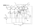
図1に示す本発明の燃料蒸発装置を備えた燃料改質装置の概略図を用いて、以下、説明する。
【0026】
本発明の燃料改質装置1は、水蒸気改質触媒を充填した燃料改質器(ATR)2と、燃料を改質ガスと熱交換して昇温する熱交換器(HEX)3と、改質ガス中の一酸化炭素を除去する第1、第2の一酸化炭素選択酸化反応器(PrOX)4、5と、燃料改質器2に燃料ガスを供給する燃料蒸発器6とから構成される。
【0027】
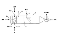
さらに燃料のガソリンを貯蔵するガソリンタンク7が備えられ、前述した燃料蒸発器6の上流側に設置した第1インジェクタ8と下流側に設置した第2インジェクタ9とから燃料蒸発器6内にガソリンを噴霧する。また水蒸気改質反応に必要な水を貯蔵する水タンク10を備え、貯蔵された水は、燃料蒸発器6の上流側に設置された第3インジェクタ11から燃料蒸発器6内に噴霧される。第2インジェクタ9の上流側には金属繊維等により形成されるフレームアレスター21が設置され(図2参照)、燃料蒸発器6内、特に後述する二次空気供給域での不均一な燃料蒸気の拡散燃焼を抑制し、ヒートスポットによるNOx生成を抑制する。
【0028】
また、空気供給源としてのコンプレッサ12を設置し、コンプレッサ12の作動により一次空気が第4インジェクタ8aからガソリンと混合して燃料蒸発器6内に噴霧される。燃料蒸発器6内には噴霧された燃料の一部を部分酸化させるためのグロープラグ13が設けられ、グロープラグ13に接し、反応した燃料の一部は酸化反応を生じて発熱する。この熱により酸素と反応せずに残留した燃料が燃料蒸気となり改質器2に供給される。燃料蒸発器6から排出された燃料蒸気にコンプレッサ12により供給される二次空気がシステム起動時に混合可能である。なお、この二次空気は加熱手段、例えば電気加熱式ヒータ14により加熱され、供給される。さらにコンプレッサ12から供給される空気は、第1、第2一酸化炭素選択酸化反応器4、5にも送られる。
【0029】
コンプレッサ12から第1、第2一酸化炭素選択酸化反応器4、5と、燃料蒸発器6と、燃料蒸発器6下流に供給される二次空気の量を制御するための制御弁15、16、17、18が各流路途中に設置される。
【0030】
前述の第1から第4インジェクタ8、9、11、8aと、コンプレッサ12と、グロープラグ13と、ヒータ14と、制御弁15から18の運転状態を制御するコントローラ19が設置され、コントローラ19には改質器2の触媒温度を検出する温度センサ20の出力が入力され、コントローラ19はこの入力された温度に基づき前述したインジェクタ等を制御する。
【0031】
このように構成され、次に燃料改質装置1の運転状態毎の作用を説明する。
【0032】
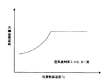
まず、燃料改質装置1の通常運転時においては、改質ガス生成のための燃料が常時第1、第2インジェクタ8、9から供給される。燃料蒸発器6に供給された燃料は空気過剰率λが0.2から0.4となるように第4インジェクタ8aから供給される空気と混合される。第1、第2インジェクタ8、9から供給される燃料は、その合計の供給量で空気過剰率λが上記範囲内、ここでは例えば0.3となるように制御され、第1、第2インジェクタ8、9の燃料供給量配分は、例えば、一定比率に制御される。
【0033】
燃料蒸発器6に供給される空気は、第4インジェクタ8aから燃料蒸発器6の長手方向に垂直に切った円筒断面における円周方向に向けて渦を形成するように供給されるので、燃料と空気の混合が促進される。また第1インジェクタ8近傍に水を供給する第3インジェクタ11が設置されるため、燃料と空気の混合気に水が効率よく混合されるとともに、燃料リッチ燃焼によるインジェクタ周りのデポジットや、部分酸化反応域での煤の形成を抑制できる。混合気はグロープラグ13に接することにより、一部に部分酸化反応が生じ、酸化反応に伴う発熱が生じる。この発熱により、部分酸化反応で酸素と反応しなかった燃料が蒸気となり、この燃料蒸気が改質器2に供給される。燃料蒸気は、改質器2に充填された改質触媒により改質され、改質ガスとなる。なお、通常運転時、二次空気の供給は停止されている。改質器2で生成された改質ガスは、下流の一酸化炭素選択反応器4、5で所定濃度まで一酸化炭素が除去され、図示しない燃料電池スタックに供給され、発電に用いられる。
【0034】
したがって、本発明においては、燃料蒸発器6に供給された燃料の一部は、同時に供給される比較的少量の空気中の酸素により部分酸化反応を生じ、酸化反応に伴う熱が発生する。この発熱により酸素と反応せずに残留した燃料が気化し、燃料蒸気となり、改質器2に供給される。燃料が蒸気となる温度は、燃料の種類により様々であるが、例えばガソリンの場合には、約280℃以上で構成されるすべての炭化水素が気化する。この温度は、部分酸化の両論比反応温度に比較して低温であるため、この反応を起こすために必要な酸素量は、燃料の種類により異なるが、式(1)に示す酸素量付近から少ない量とする必要がある。このように、少ない酸素量で燃料を燃焼させることにより、過剰な部分酸化反応を抑制しつつ、燃料を蒸発させることができ、十分な燃料蒸気を改質器2に供給し、水蒸気改質反応により改質ガスを生成することができる。
【0035】
また、燃料蒸発器6内の混合気の空気過剰率λを完全燃焼空気量に対して空気と燃料の導入量比で、0.2〜0.4に設定したので、燃料の蒸発に必要な反応熱量を確保しつつ、過剰な部分酸化反応を抑制し、下流の改質器2内に充填した水蒸気改質触媒に燃料蒸気を十分に供給することができる。言い換えると、空気過剰率λが0.2から0.4となるように空気流量を制限することで、部分酸化により消費される燃料量を抑制して改質器2に供給されるべき燃料量を確保し、この消費された燃料の発熱により、残留した燃料を蒸発させ、改質器2に燃料蒸気として残留した燃料を供給できる。このとき、設定すべき空気と燃料の比率(空気過剰率λ)は、燃料の性状や燃料蒸発器6の形状、空気及び水の供給方法により変化するが、実験的、あるいは経験的に得られた燃料蒸気の発生量と燃焼蒸発反応の安定性の結果から、好適な空気過剰率λとして0.2〜0.4が設定される。
【0036】
また、燃料蒸発器6内で燃料と空気の混合気に第3インジェクタ11から水を噴霧し、混合することで、部分酸化反応と同時に進行する、煤の生成やコーキングの発生を抑制しつつ、燃料蒸気と反応熱で水蒸気化した水の混合が促進し、下流の改質器2での水蒸気改質反応が促進される。
【0037】
次に燃料改質装置1の起動運転時について説明する。
【0038】
まず、通常運転時と同様に燃料蒸発器6内にインジェクタから燃料と空気とを供給し、部分酸化反応を生じさせてその燃焼熱により燃料を蒸発させる。燃料蒸気は燃料蒸発器6の下流側で二次空気と混合され、改質器2に送られる。二次空気は、燃料蒸気の流れに対して渦を巻くように供給され、燃料と空気の混合が促進される。燃料蒸気と二次空気の混合気は、改質器2に送られて、改質器2内の改質触媒上で速やかに燃焼反応を起こし、この燃焼ガスの熱で改質器2を暖機する。このときの燃料蒸気と空気の混合気の空気過剰率λは改質器2の入口で3から6となるように燃料量と空気量を制御する。
【0039】
次に、温度センサ20により検出される改質器2の触媒温度が、部分酸化反応により昇温し、暖機完了温度に達したら、さらに触媒温度を高温の改質温度(通常運転時の触媒温度)にまで昇温させる為に二次空気の供給量を減少して、燃焼ガスの温度を上昇させ、二次空気量の供給が0になる通常運転時に改質器2の触媒温度を改質触媒として機能する温度まで上昇させる。このような加熱方法とすることで、改質器2に熱衝撃を与えることがない。
【0040】
なお、二次空気は予めヒータ14により加熱されているため、高温の空気により改質器2での燃焼が確実に行われ、空気過剰率(λ=3〜6)の高い燃焼を維持することができる。また、燃料蒸発器6で燃料の蒸発が開始される前に空気の加熱を開始し、この加熱された空気により改質器2の改質触媒を暖機することで、燃料蒸気が低温の改質触媒に吸着被毒することを防止し、触媒の燃焼反応を速やかに開始でき、起動直後の燃料蒸気が改質器2から排出されることを防止できる。
【0041】
このように、燃料蒸発器6から排出された燃料蒸気が二次空気と混合された後、改質器2に供給されて燃焼することで、暖機中には、排気悪化に繋がる燃料蒸気及び部分酸化反応で生じたCOやH2を燃焼除去しつつ、その燃焼で得られた高温、且つ燃料蒸気に比して二次空気分だけ増加した燃焼ガスを発生させ、下流に設置した燃料改質器2や一酸化炭素選択酸化反応器4、5、燃料電池スタックを暖機することができる。
【0042】
暖機時の空気過剰率λは改質器2の入口で3から6に設定されている。空気過剰率λを3以上に設定することにより、空気過剰率λが低すぎ、余剰空気が少なく改質反応場温度が上昇してNOxが生成し、排気中にNOxが含まれたまま排出されるのを防止することができる。また、空気過剰率λを6以下とすることで、システム中の燃料改質器2と第1、第2一酸化炭素選択酸化反応器4、5の暖機に必要な燃焼ガス温度を確保することができる。
【0043】
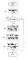
図3は、燃料改質装置1の暖機運転時の制御内容を説明するフローチャートである。この制御はコントローラ19によって実施される。
【0044】
まずステップ1で、温度センサ20を用いて改質触媒温度Tcを検出する。続くステップ2で、検出した改質触媒温度Tcが改質器2の暖機温度TCWを越えているかを判定する。改質器2の暖機温度以上であれば制御を終了し、下回っていればステップ3に進む。
【0045】
ステップ3では、検出した改質触媒温度Tcに基づき燃料噴射量Qfを図4に示すようなマップを用いて算出するとともに空気過剰率λ=0.3を維持するのに必要な一次空気供給量Qa1を演算する。続くステップ4では、検出した改質触媒温度Tcに基づき改質触媒へ供給する混合気の空気過剰率λを図5に示すようなマップを用いて算出する。そしてステップ5で、ステップ3、4の演算結果に基づき、第1、第2インジェクタ8、9と、一次空気供給バルブ17、二次空気供給バルブ18を制御する。
【0046】
燃料改質装置1の具体的な制御方法の一例を説明すると、起動時には、燃料流量、一次空気量、二次空気量をそれぞれ所定量(例えば、最大流量の半分)供給し(但し、このときの空気過剰率λは3から6)、改質触媒温度を上昇させ、確実に酸化反応が起きていることを検知したら(例えば、改質器2の温度が暖機温度より高い)、二次空気量を減少して、空気過剰率λを通常時の0.2から0.4として通常運転時に改質触媒として機能する温度まで改質触媒の温度を上昇させる。通常運転時には、0.2から0.4の空気過剰率λを維持しつつ、燃料流量と一次空気量は燃料電池の要求発電量に応じて設定される。
【0047】
本発明は、上記した実施形態に限定されるものではなく、本発明の技術的思想の範囲内でさまざまな変更がなしうることは明白である。
【図面の簡単な説明】
【図1】本発明の燃料改質装置の構成図である。
【図2】燃料蒸発器の詳細構成図である。
【図3】燃料改質装置の暖機時の制御を説明するフローチャートである。
【図4】改質触媒温度と燃料噴射量の関係を示す図である。
【図5】改質触媒温度と蒸発器出口での空気過剰率との関係を示す図である。
【符号の説明】
1 燃料改質装置
2 燃料改質器
3 熱交換器
4 第1一酸化炭素選択酸化反応器
5 第2一酸化炭素選択酸化反応器
6 燃料蒸発器
7 ガソリンタンク
8 第1インジェクタ
8a 第4インジェクタ
9 第2インジェクタ
10 水タンク
11 第3インジェクタ
12 コンプレッサ
13 グロープラグ
14 ヒータ
15 制御弁
16 制御弁
17 制御弁
18 制御弁
19 コントローラ
20 温度センサ
21 フレームアレスター[0001]
BACKGROUND OF THE INVENTION
The present invention relates to a fuel evaporation device, and more particularly to a fuel evaporation device that supplies fuel vapor to a fuel reformer.
[0002]
[Prior art]
As a technology related to the conventional fuel reformer, a part of the reformed gas discharged from the fuel reformer is supplied to the combustor, and the amount of reformed gas supplied is compared with a predetermined amount, or the reformed gas temperature is adjusted. There is a technique for comparing with a predetermined temperature (see, for example, Patent Document 1).
[0003]
Further, a raw material input amount calculating means for calculating a raw material input amount target value to be input to the evaporator according to a required output value of the fuel cell, a heat amount balance estimating means for estimating a heat amount balance in the evaporator, and the heat amount balance There is a technique related to a fuel reformer control device including a combustor control means for controlling the combustor based on a heat amount balance in the evaporator estimated by an estimation means (see, for example, Patent Document 2).
[0004]
In addition, as a technology related to a combustor that supplies fuel gas to a reformer, a combustion catalyst of the combustor includes a heating unit for heating the oxygen-containing gas and a combustion catalyst unit connected to the downstream side of the heating unit. (For example, refer to Patent Document 3).
[0005]
Further, the fuel reformer includes a reforming chamber in which the reforming catalyst unit is disposed, and a start-up combustion chamber that supplies gas combusted in the combustion chamber to the reforming catalyst unit. There is a technique characterized by comprising a fuel injection means for supplying heating fuel to the combustion chamber and an ignition plug for igniting the heating fuel supplied to the combustion chamber (see, for example, Patent Document 4).
[0006]
A fuel reformer having a first chamber provided with a reforming catalyst layer therein and a second chamber disposed adjacent to the first chamber and introducing a cooling medium into the first chamber. There is a technique characterized by this (for example, refer to Patent Document 5).
[0007]
A hydrocarbon-based fuel is added with steam in a liquid phase and a gas phase, introduced into a reforming reactor, carbon monoxide, hydrogen preheated to 250 ° C. to 900 ° C. by a reforming catalyst of 250 ° C. or higher, There is a technique in which reformed gas rich in carbon dioxide is discharged from a reforming reactor and supplied to a heater (see, for example, Patent Document 6).
[0008]
Another reforming apparatus, which forms a heating chamber along an outer wall surface of a reaction tube filled with a reforming catalyst and arranged in the vertical direction, and includes a combustor at a position below the heating chamber. There is a technique characterized by this (for example, refer to Patent Document 7).
[0009]
A fuel reforming system for the purpose of preventing thermal stress destruction of a structural material of a reforming section due to overheating of a burner, and reforming the vaporized section that vaporizes fuel and the vaporized fuel to generate hydrogen A reformer that generates a rich gas, and a combustor that generates a heat source gas that is sent to the vaporization unit and the reforming unit of the reformer, respectively, and the combustor includes a cooling unit that sprays cooling water. (For example, refer to Patent Document 8).
[0010]
A combustor for a reformer, which prevents overheating of the reforming section, prevents differences in temperature distribution in the reforming catalyst, and further widens the selection range of constituent materials of the reformer And a heat source gas conversion unit that controls the amount of heat generated by the heat source generation unit and converts it into a heat source gas of a certain amount of heat, and the heat source gas conversion unit (1) is made of a refractory heat storage material so as to surround the heat source generation unit. And (2) an exhaust gas outlet through which the exhaust gas generated from the heat source generator is passed, and a heat medium flow path through which the heat medium passes and performs heat exchange, and (3) There is a technology having a heat source gas discharge port for discharging a heat source gas formed by joining heat media (see, for example, Patent Document 9).
[0011]
[Patent Document 1]
Japanese Patent Laid-Open No. 2001-223016 [Patent Document 2]
JP 2001-210347A [Patent Document 3]
JP 2001-27403 A [Patent Document 4]
JP 2000-63104 A [Patent Document 5]
JP-A-8-189380 [Patent Document 6]
JP-A-8-188784 [Patent Document 7]
JP-A-8-2901 gazette
[Patent Document 8]
JP-A-7-172802 [0013]
[Patent Document 9]
Japanese Patent Laid-Open No. 7-103090 [0014]
[Problems to be solved by the invention]
In the conventional technology, it is necessary to evaporate fuel and water composed of hydrocarbon fuels such as gasoline and methanol before supplying them to the reforming catalyst in order to cause the reforming reaction in the reformer. The resulting fuel is immediately partially oxidized in the gas phase, and a slow reaction such as steam reforming, which is a reaction between H 2 O and the fuel, cannot be expected. For this reason, there exists a subject that the reforming efficiency which is the production efficiency of hydrogen obtained by reforming is low.
[0015]
The reason why the reforming efficiency is low will be explained with octane (C 8 H 18 ), which is abundant in hydrocarbon fuels such as gasoline.
[0016]
First, the reaction formula of each reforming reaction is expressed as follows.
Partial oxidation reaction C 8 H 18 + (8/2) O 2 → 8CO + 9H 2 + ΔQ (1)
Steam reforming reaction C 8 H 18 + 8H 2 O → 8CO + 17H 2 −ΔQ (2)
From the above equation, it can be seen that the amount of H 2 produced from 1 mol of the same octane is about 1.9 times that of the partial oxidation reaction in the steam reforming reaction. Here, the partial oxidation reaction is an exothermic reaction, and the steam reforming reaction is an endothermic reaction.
[0017]
The reason why the reformer of the burner system as described in
[0018]
On the other hand, comparing the reaction rates of the two reforming reactions, which is not discussed in equilibrium, the partial oxidation reaction is generally faster than the steam reforming reaction. This is clear from the fact that even in the presence of high-temperature steam, the partial oxidation reaction occurs in the gas phase, but the steam reforming reaction always requires activation by a catalyst.
[0019]
From the above, in the case of a reformer in which reforming is performed in the gas layer by a flame of 700 ° C. or higher obtained by vaporizing and igniting the fuel, partial oxidation is particularly performed in the gas phase burner part as described in
[0020]
In general, it is known that when a catalyst in a cold state is exposed to fuel vapor or CO contained in the fuel vapor before being activated, they are adsorbed on the catalyst surface and raise the starting temperature of the catalytic reaction. In order to solve this problem, the technique described in
[0021]
Further, here, it is considered that an air-layer combustion type burner as described in
Complete oxidation C 8 H 18 + (25/2) O 2 → 8CO 2 + 9H 2 O + ΔQ (3)
In this case, assuming that the combustion is from 1 atm and 25 ° C., the adiabatic field temperature is 1884 ° C., which exceeds the heat resistance temperature of a normal reformer component. As a countermeasure, if the amount of combustion air is 3 times the theoretical complete combustion amount (excess air ratio λ = 3), the heat field of the reaction field becomes 887 ° C due to the heat capacity of the added air, and the heat resistance of the material Can be solved. However, in reality, combustion with the amount of combustion air set to three times the theoretical complete combustion amount is achieved with a gas-phase combustor because of the non-uniform mixing ratio of fuel and air due to high temperature heat spots and flames. Blowout occurs and is very difficult.
[0022]
The present invention has been made in view of the above-described problems of the prior art, and an object of the present invention is to supply a sufficient amount of fuel to the reformer while suppressing partial oxidation of the fuel vapor. An object of the present invention is to provide a fuel evaporation device that can perform a reforming reaction and can reliably vaporize a liquid fuel.
[0023]
[Means for Solving the Problems]
The present invention provides a fuel evaporation device for supplying fuel vapor to the fuel reformer, supplying air to combust a portion of the fuel supplied to evaporate the fuel remaining in the combustion heat, the evaporation Mix secondary air with the spent fuel.
[0024]
【The invention's effect】
According to the present invention, since only a part of the supplied fuel is combusted, an excessive partial oxidation reaction can be suppressed, and the fuel that has not been combusted can be evaporated by the combustion heat. It can be supplied to the fuel reformer in a vaporized state. Thereby, the reformed gas can be efficiently generated by the steam reforming reaction in the fuel reformer.
[0025]
DETAILED DESCRIPTION OF THE INVENTION
This will be described below with reference to the schematic diagram of the fuel reformer equipped with the fuel evaporation apparatus of the present invention shown in FIG.
[0026]
The
[0027]
Further, a gasoline tank 7 for storing fuel gasoline is provided, and gasoline is supplied into the
[0028]
In addition, a
[0029]
The first and second carbon monoxide selective oxidation reactors 4 and 5 from the
[0030]
A
[0031]
Next, the operation of each operation state of the
[0032]
First, during normal operation of the
[0033]
The air supplied to the
[0034]
Therefore, in the present invention, a part of the fuel supplied to the
[0035]
Further, since the excess air ratio λ of the air-fuel mixture in the
[0036]
In addition, by spraying water from the third injector 11 to the fuel / air mixture in the
[0037]
Next, the start-up operation of the
[0038]
First, as in the normal operation, fuel and air are supplied from the injector into the
[0039]
Next, when the catalyst temperature of the
[0040]
Since the secondary air is preheated by the
[0041]
In this way, after the fuel vapor discharged from the
[0042]
The excess air ratio λ during warm-up is set to 3 to 6 at the inlet of the
[0043]
FIG. 3 is a flowchart for explaining the control contents during the warm-up operation of the
[0044]
First, in
[0045]
In
[0046]
An example of a specific control method of the
[0047]
The present invention is not limited to the above-described embodiment, and it is obvious that various modifications can be made within the scope of the technical idea of the present invention.
[Brief description of the drawings]
FIG. 1 is a configuration diagram of a fuel reformer of the present invention.
FIG. 2 is a detailed configuration diagram of a fuel evaporator.
FIG. 3 is a flowchart illustrating control during warm-up of the fuel reformer.
FIG. 4 is a diagram showing a relationship between a reforming catalyst temperature and a fuel injection amount.
FIG. 5 is a diagram showing the relationship between the reforming catalyst temperature and the excess air ratio at the evaporator outlet.
[Explanation of symbols]
DESCRIPTION OF
Claims (11)
前記燃料蒸発装置内に供給される燃料の一部を燃焼するように空気を供給し、その燃焼熱により残留した燃料を蒸発させ、
前記燃料蒸発装置内で蒸発した燃料に二次空気を混合する
ことを特徴とする燃料蒸発装置。A fuel evaporation device that supplies fuel vapor obtained by vaporizing fuel to a fuel reformer that generates reformed gas,
Supplying air so as to burn a part of the fuel supplied into the fuel evaporation device, evaporating the remaining fuel by the combustion heat ;
A fuel evaporation apparatus, wherein secondary air is mixed with fuel evaporated in the fuel evaporation apparatus.
Priority Applications (4)
| Application Number | Priority Date | Filing Date | Title |
|---|---|---|---|
| JP2003003594A JP4457559B2 (en) | 2003-01-09 | 2003-01-09 | Fuel evaporator |
| EP03778774A EP1581334B1 (en) | 2003-01-09 | 2003-12-10 | Fuel vaporizing device |
| PCT/JP2003/015788 WO2004062788A1 (en) | 2003-01-09 | 2003-12-10 | Fuel vaporizing device |
| US10/541,382 US7146801B2 (en) | 2003-01-09 | 2003-12-10 | Fuel vaporizing device |
Applications Claiming Priority (1)
| Application Number | Priority Date | Filing Date | Title |
|---|---|---|---|
| JP2003003594A JP4457559B2 (en) | 2003-01-09 | 2003-01-09 | Fuel evaporator |
Publications (2)
| Publication Number | Publication Date |
|---|---|
| JP2004217439A JP2004217439A (en) | 2004-08-05 |
| JP4457559B2 true JP4457559B2 (en) | 2010-04-28 |
Family
ID=32708915
Family Applications (1)
| Application Number | Title | Priority Date | Filing Date |
|---|---|---|---|
| JP2003003594A Expired - Lifetime JP4457559B2 (en) | 2003-01-09 | 2003-01-09 | Fuel evaporator |
Country Status (4)
| Country | Link |
|---|---|
| US (1) | US7146801B2 (en) |
| EP (1) | EP1581334B1 (en) |
| JP (1) | JP4457559B2 (en) |
| WO (1) | WO2004062788A1 (en) |
Cited By (1)
| Publication number | Priority date | Publication date | Assignee | Title |
|---|---|---|---|---|
| KR20200118160A (en) * | 2018-02-26 | 2020-10-14 | 프랙스에어 테크놀로지, 인코포레이티드 | Integration of high temperature oxygen burner and autothermal reformer |
Families Citing this family (28)
| Publication number | Priority date | Publication date | Assignee | Title |
|---|---|---|---|---|
| US7967878B2 (en) * | 2002-01-04 | 2011-06-28 | Meggitt (Uk) Limited | Reformer apparatus and method |
| JP2008500258A (en) * | 2004-05-17 | 2008-01-10 | ヌヴェラ・フュエル・セルズ・インコーポレーテッド | Starting burner |
| US20050274107A1 (en) * | 2004-06-14 | 2005-12-15 | Ke Liu | Reforming unvaporized, atomized hydrocarbon fuel |
| FR2876500B1 (en) * | 2004-10-08 | 2007-08-10 | Renault Sas | ELECTRICITY GENERATOR FOR MOTOR VEHICLE |
| DE102004062152A1 (en) * | 2004-12-23 | 2006-07-13 | Bayerische Motoren Werke Ag | System of a fuel cell and an internal combustion engine |
| DE102005048385A1 (en) * | 2005-10-10 | 2007-04-19 | Fraunhofer-Gesellschaft zur Förderung der angewandten Forschung e.V. | Process for the evaporation and reforming of liquid fuels |
| RU2324745C2 (en) * | 2006-02-26 | 2008-05-20 | Игорь Михайлович Дистергефт | Method of thermal processing of metal in combustion furnace of either direct or indirect reheating (variants), method of burning of mixture of liquid or gazeous fuel and heated air in combustion furnace of either direct or indirect reheating, heating mechanism (variants) and regenerative capping (variants) to implement these procedures |
| DE102006025664B4 (en) | 2006-06-01 | 2018-03-08 | Faurecia Emissions Control Technologies, Germany Gmbh | Assembly for generating a hydrogen-containing gas |
| DE102006063063B3 (en) | 2006-06-01 | 2021-12-30 | Faurecia Emissions Control Technologies, Germany Gmbh | Assembly for generating a hydrogen-containing gas |
| DE102006042537A1 (en) * | 2006-09-11 | 2008-03-27 | Enerday Gmbh | Fuel cell system and method for starting a fuel cell system |
| WO2008052361A1 (en) * | 2006-11-03 | 2008-05-08 | Nxtgen Emission Controls Inc. | Fuel processor |
| KR100836367B1 (en) * | 2006-11-21 | 2008-06-09 | 현대자동차주식회사 | Purifier for Reducing Particulate Matter and Nitrogen Oxide in Diesel Engine |
| US20080230039A1 (en) * | 2007-03-22 | 2008-09-25 | Weiss Amanda M | Continuous liquid fuel vaporizer |
| JP5164441B2 (en) * | 2007-06-13 | 2013-03-21 | Jx日鉱日石エネルギー株式会社 | Starting method of fuel cell system |
| JP5149647B2 (en) * | 2008-02-20 | 2013-02-20 | 本田技研工業株式会社 | Fuel reformer |
| JP5416945B2 (en) * | 2008-10-31 | 2014-02-12 | 東芝燃料電池システム株式会社 | Fuel cell power generation system |
| US9140220B2 (en) | 2011-06-30 | 2015-09-22 | Lg Fuel Cell Systems Inc. | Engine systems and methods of operating an engine |
| US9178235B2 (en) | 2009-09-04 | 2015-11-03 | Lg Fuel Cell Systems, Inc. | Reducing gas generators and methods for generating a reducing gas |
| US9118048B2 (en) | 2009-09-04 | 2015-08-25 | Lg Fuel Cell Systems Inc. | Engine systems and methods of operating an engine |
| US9083020B2 (en) * | 2009-09-04 | 2015-07-14 | Lg Fuel Cell Systems Inc. | Reducing gas generators and methods for generating reducing gas |
| US8495973B2 (en) * | 2009-11-03 | 2013-07-30 | Protonex Technology Corporation | Thin film vaporizer |
| CN103649475B (en) * | 2011-07-11 | 2015-07-15 | 哈茨有限公司 | Advanced combined cycle systems and methods based on methanol indirect combustion |
| DE102013210116B3 (en) * | 2013-05-29 | 2014-05-28 | Mtu Friedrichshafen Gmbh | Internal combustion engine and method for operating an internal combustion engine |
| WO2015044628A1 (en) * | 2013-09-25 | 2015-04-02 | Thompson Dennis Mark | Cleaning machine |
| CN104848245B (en) * | 2015-03-20 | 2017-09-12 | 佛山市伟华文五金机械制造有限公司 | Small-sized welding oil/gas convertor |
| JP6443404B2 (en) * | 2016-07-04 | 2018-12-26 | トヨタ自動車株式会社 | Heat, hydrogen generator |
| CN106678860B (en) * | 2017-01-23 | 2019-01-18 | 山东理工大学 | A kind of leveling style Horizontal gas generator and its produce gas technique |
| WO2024246064A1 (en) * | 2023-06-01 | 2024-12-05 | Casale Sa | Procedure for reducing soot formation in a pox reactor during transients |
Family Cites Families (21)
| Publication number | Priority date | Publication date | Assignee | Title |
|---|---|---|---|---|
| DE4006666A1 (en) | 1990-03-03 | 1991-09-05 | Hoechst Ag | METHOD FOR PRODUCING 3-NITROBENZENE SULPHONIC ACID CHLORIDE |
| EP0573522B1 (en) | 1991-03-01 | 1994-12-14 | Pfizer Inc. | 1-azabicyclo[3.2.2]nonan-3-amine derivatives |
| JPH07103090A (en) | 1993-09-30 | 1995-04-18 | Aqueous Res:Kk | Combustor for fuel reformer and fuel reforming method |
| JPH07172802A (en) | 1993-12-15 | 1995-07-11 | Aqueous Res:Kk | Fuel reforming system |
| JPH082901A (en) | 1994-06-15 | 1996-01-09 | Daikin Ind Ltd | Fuel cell reformer |
| JPH08188784A (en) | 1995-01-06 | 1996-07-23 | Nippon Steel Corp | Reheating furnace fuel reforming method |
| JP3196549B2 (en) | 1995-01-09 | 2001-08-06 | 株式会社日立製作所 | Power generation system with fuel reformer |
| DE19717544A1 (en) | 1997-04-25 | 1998-10-29 | Eberspaecher J Gmbh & Co | Evaporator burner for a heater or a thermal regeneration of an exhaust gas particle filter |
| US6282902B1 (en) | 1997-10-28 | 2001-09-04 | Hitachi, Ltd. | Waste processing system and fuel reformer used in the waste processing system |
| JP3750970B2 (en) | 1998-08-12 | 2006-03-01 | 本田技研工業株式会社 | Fuel reformer and control method thereof |
| EP1147287B1 (en) * | 1998-12-22 | 2005-08-17 | Weatherford/Lamb, Inc. | Procedures and equipment for profiling and jointing of pipes |
| JP3697955B2 (en) | 1999-07-13 | 2005-09-21 | 日産自動車株式会社 | Catalytic combustor and method for raising temperature |
| JP3864658B2 (en) | 2000-01-26 | 2007-01-10 | 日産自動車株式会社 | Control device for fuel reformer |
| US6451465B1 (en) | 2000-02-07 | 2002-09-17 | General Motors Corporation | Method for operating a combustor in a fuel cell system |
| JP3398862B2 (en) * | 2000-07-06 | 2003-04-21 | 本田技研工業株式会社 | How to warm up the fuel evaporator |
| JP3642270B2 (en) * | 2000-09-12 | 2005-04-27 | 日産自動車株式会社 | Fuel reformer |
| JP3874334B2 (en) * | 2000-10-13 | 2007-01-31 | 本田技研工業株式会社 | Fuel cell system |
| JP2002179401A (en) | 2000-12-11 | 2002-06-26 | Toyota Motor Corp | Method of shutting down operation of hydrogen gas generation system |
| JP3700603B2 (en) * | 2001-04-06 | 2005-09-28 | 日産自動車株式会社 | Fuel cell system |
| JP3693291B2 (en) * | 2001-05-15 | 2005-09-07 | 本田技研工業株式会社 | Raw fuel evaporation apparatus, raw fuel evaporation method, and fuel cell system including raw fuel evaporation apparatus |
| US6838062B2 (en) | 2001-11-19 | 2005-01-04 | General Motors Corporation | Integrated fuel processor for rapid start and operational control |
-
2003
- 2003-01-09 JP JP2003003594A patent/JP4457559B2/en not_active Expired - Lifetime
- 2003-12-10 US US10/541,382 patent/US7146801B2/en not_active Expired - Lifetime
- 2003-12-10 EP EP03778774A patent/EP1581334B1/en not_active Expired - Lifetime
- 2003-12-10 WO PCT/JP2003/015788 patent/WO2004062788A1/en not_active Ceased
Cited By (4)
| Publication number | Priority date | Publication date | Assignee | Title |
|---|---|---|---|---|
| KR20200118160A (en) * | 2018-02-26 | 2020-10-14 | 프랙스에어 테크놀로지, 인코포레이티드 | Integration of high temperature oxygen burner and autothermal reformer |
| KR102493874B1 (en) | 2018-02-26 | 2023-02-06 | 프랙스에어 테크놀로지, 인코포레이티드 | Integration of high-temperature oxygen burners and autothermal reformers |
| KR20230020575A (en) * | 2018-02-26 | 2023-02-10 | 프랙스에어 테크놀로지, 인코포레이티드 | Integration of a hot oxygen burner with an auto thermal reformer |
| KR102650849B1 (en) | 2018-02-26 | 2024-03-26 | 프랙스에어 테크놀로지, 인코포레이티드 | Integration of a hot oxygen burner with an auto thermal reformer |
Also Published As
| Publication number | Publication date |
|---|---|
| US20060037308A1 (en) | 2006-02-23 |
| JP2004217439A (en) | 2004-08-05 |
| EP1581334A1 (en) | 2005-10-05 |
| US7146801B2 (en) | 2006-12-12 |
| EP1581334B1 (en) | 2011-06-15 |
| WO2004062788A1 (en) | 2004-07-29 |
Similar Documents
| Publication | Publication Date | Title |
|---|---|---|
| JP4457559B2 (en) | Fuel evaporator | |
| US7037349B2 (en) | Method and apparatus for fuel/air preparation in a fuel cell | |
| EP1927579A1 (en) | Electrically-heated metal vaporizer for fuel / air preparation in a hydrocarbon reformer assembly | |
| JP2004018363A (en) | Fuel reformer | |
| JP3642270B2 (en) | Fuel reformer | |
| CN100583529C (en) | Controls for catalytic burners | |
| US10629926B2 (en) | Solid oxide fuel cell system | |
| JP3398862B2 (en) | How to warm up the fuel evaporator | |
| JP2004149407A (en) | Hydrogen generator and power generator using the same | |
| JP2010266160A (en) | Combustion device | |
| JP4622066B2 (en) | Hydrogen generator | |
| JP3856423B2 (en) | Starting method of hydrogen generator | |
| JP7663474B2 (en) | Engine System | |
| US20050095544A1 (en) | Evaporator arrangement for generating a hydrocarbon/air or hydrocarbon/steam mixture that can be decomposed in a reformer for producing hydrogen and process for operating such an evaporator arrangement | |
| JP5309799B2 (en) | Reformer and fuel cell system | |
| JP3804436B2 (en) | Reformer | |
| JP4973080B2 (en) | How to start the reformer | |
| JP3815248B2 (en) | Reformer | |
| JP2003238108A (en) | Fuel reforming apparatus and fuel reforming method | |
| JP5471192B2 (en) | Hydrogen generator and its start / stop method | |
| JP2004035308A (en) | Partial oxidation reformer | |
| JP5525756B2 (en) | Combustion device | |
| JP2009140686A (en) | Liquid fuel vaporizer, method and liquid fuel vaporization system | |
| JP2003277007A (en) | Hydrogen generator | |
| JP2004168607A (en) | Fuel reformer |
Legal Events
| Date | Code | Title | Description |
|---|---|---|---|
| A621 | Written request for application examination |
Free format text: JAPANESE INTERMEDIATE CODE: A621 Effective date: 20051124 |
|
| A131 | Notification of reasons for refusal |
Free format text: JAPANESE INTERMEDIATE CODE: A131 Effective date: 20090106 |
|
| A521 | Request for written amendment filed |
Free format text: JAPANESE INTERMEDIATE CODE: A523 Effective date: 20090126 |
|
| TRDD | Decision of grant or rejection written | ||
| A01 | Written decision to grant a patent or to grant a registration (utility model) |
Free format text: JAPANESE INTERMEDIATE CODE: A01 Effective date: 20100119 |
|
| A01 | Written decision to grant a patent or to grant a registration (utility model) |
Free format text: JAPANESE INTERMEDIATE CODE: A01 |
|
| A61 | First payment of annual fees (during grant procedure) |
Free format text: JAPANESE INTERMEDIATE CODE: A61 Effective date: 20100201 |
|
| R150 | Certificate of patent or registration of utility model |
Ref document number: 4457559 Country of ref document: JP Free format text: JAPANESE INTERMEDIATE CODE: R150 Free format text: JAPANESE INTERMEDIATE CODE: R150 |
|
| FPAY | Renewal fee payment (event date is renewal date of database) |
Free format text: PAYMENT UNTIL: 20130219 Year of fee payment: 3 |
|
| FPAY | Renewal fee payment (event date is renewal date of database) |
Free format text: PAYMENT UNTIL: 20130219 Year of fee payment: 3 |
|
| FPAY | Renewal fee payment (event date is renewal date of database) |
Free format text: PAYMENT UNTIL: 20140219 Year of fee payment: 4 |
|
| EXPY | Cancellation because of completion of term |