JP4457501B2 - Air conditioner for vehicles - Google Patents
Air conditioner for vehicles Download PDFInfo
- Publication number
- JP4457501B2 JP4457501B2 JP2001029973A JP2001029973A JP4457501B2 JP 4457501 B2 JP4457501 B2 JP 4457501B2 JP 2001029973 A JP2001029973 A JP 2001029973A JP 2001029973 A JP2001029973 A JP 2001029973A JP 4457501 B2 JP4457501 B2 JP 4457501B2
- Authority
- JP
- Japan
- Prior art keywords
- air conditioning
- air
- conditioning zone
- zone
- absent
- Prior art date
- Legal status (The legal status is an assumption and is not a legal conclusion. Google has not performed a legal analysis and makes no representation as to the accuracy of the status listed.)
- Expired - Fee Related
Links
Images


Description
【0001】
【発明の属する技術分野】
本発明は、車室内の前後の各空調ゾーンをそれぞれ独立に空調制御可能であるとともに、前側空調ゾーンの右側および左側の各空調ゾーンをそれぞれ独立に空調制御可能である車両用空調装置に関するものである。
【0002】
【従来の技術】
従来、特開平5−193337号公報において、後席の左右の各空調ゾーンを同一の目標吹出温度で空調制御する車両用空調装置が提案されている。この従来装置では、左右の各吹出口からの空調風の配風割合を日射の向きに応じて制御するようにして、左右方向の片側から日射を受ける偏日射の場合であっても、後席の左右の各乗員がともに快適な温感を得られるようにしている。
【0003】
【発明が解決しようとする課題】
しかし、上記公報の従来技術では、左右各吹出口で異なる風量を吹き出すための配風機構を必要とするため、大きな製造原価アップを招いてしまう。
【0004】
また、この配風機構は大きな搭載スペースを必要とし、特に、車室内後方に設置される後席用空調装置に配風機構を搭載する場合には、搭載スペースが非常に狭いため、配風機構の搭載が困難である。
【0005】
本発明は、上記点に鑑み、偏日射の有無に関わらず後側空調ゾーンの左右の各乗員がともに快適な温感を得られるようにすることを、配風機構を用いることなく実現することを目的とする。
【0006】
【課題を解決するための手段】
上記目的を達成するため、請求項1に記載の発明では、車室内(100)の前側空調ゾーン(101a、102a)と後側空調ゾーン(103a、103b)とをそれぞれ独立に空調制御するとともに、前側空調ゾーンの右側空調ゾーン(101a)と左側空調ゾーン(102a)とをそれぞれ独立に空調制御する車両用空調装置において、前側空調ゾーン(101a、102a)の乗員の上半身に向けて空調空気を吹き出すフェイス吹出口(100Dr、100Pa)と、右側および左側空調ゾーン(101a、102a)のうち少なくとも一方の空調ゾーンの乗員が、不在であるかを判定する判定手段(S410)とを備え、判定手段(S410)が乗員不在を判定した場合に、不在側の空調ゾーン(102a)に吹き出される空調空気により、後側空調ゾーン(103a、103b)のうち不在側の空調ゾーン(102a)の後方に位置する不在側後方空調ゾーン(103b)を空調制御するとともに、不在側の空調ゾーン(102a)の吹出モードを、フェイス吹出口(100Pa)から空調空気を吹き出すフェイス吹出モードにするようになっていることを特徴とする。
【0007】
これにより、後側空調ゾーン(103a、103b)のうち不在側後方空調ゾーン(103b)は、不在側の空調ゾーン(102a)に吹き出される空調空気により空調制御されるので、後側空調ゾーン(103a、103b)の左右を異なる空調状態にできる。よって、偏日射の場合であっても、後側空調ゾーンの左右の各乗員がともに快適な温感を得られるようにすることを、配風機構を用いることなく実現できる。
【0008】
例えば、左側空調ゾーン(102a)の乗員が不在であり、車両の左側から日射を受ける場合には、後側空調ゾーン(103a、103b)の左右に吹き出される空調空気の温度を、後側空調ゾーン(103a、103b)の右側の乗員が快適な温感を得られるように制御する。そして、左側空調ゾーン(102a)に吹き出される空調空気の温度を、後側空調ゾーン(103a、103b)に吹き出される空調空気の温度より低くすれば、後側空調ゾーン(103a、103b)の左側の乗員が日射により暑く感じることを打ち消すことができる。
【0011】
ところで、不在側の空調ゾーン(102a)がフェイス吹出モードの場合には、他の吹出モードの場合に比べて、不在側の空調ゾーン(102a)に吹き出される空調空気が不在側後方空調ゾーン(103b)に流れ易くなる。よって、不在側の空調ゾーン(102a)に吹き出される空調空気により不在側後方空調ゾーン(103b)の空調状態が影響を受ける度合は、不在側の空調ゾーン(102a)がフェイス吹出モードの場合に最も大きくなる。
【0012】
そこで、請求項1に記載の発明のように、前側空調ゾーン(101a、102a)の乗員の上半身に向けて空調空気を吹き出すフェイス吹出口(100Dr、100Pa)を備え、判定手段(S410)が乗員不在を判定した場合には、不在側の空調ゾーン(102a)の吹出モードを、フェイス吹出口(100Pa)から空調空気を吹き出すフェイス吹出モードにすれば、不在側の空調ゾーン(102a)に吹き出される空調空気により、不在側後方空調ゾーン(103b)を空調制御することを容易にできる。
【0013】
また、請求項2に記載の発明では、フェイス吹出口(100Pa)の吹き出し向きを変える風向可変手段を備え、判定手段(S410)が乗員不在を判定した場合には、フェイス吹出口(100Pa)からの空調空気が助手席(102)を避けて不在側後方空調ゾーン(103b)に流れるように、風向可変手段を制御することを特徴とするので、不在側の空調ゾーン(102a)に吹き出される空調空気が不在側後方空調ゾーン(103b)に、より一層流れ易くなる。よって、不在側の空調ゾーン(102a)に吹き出される空調空気により、不在側後方空調ゾーン(103b)を空調制御することをより一層容易にできる。
【0014】
また、請求項3、4に記載の発明では、判定手段(S410)が乗員不在を判定した場合には、不在側の空調ゾーン(102a)に吹き出される空調空気の風量を多くすることを特徴とするので、不在側の空調ゾーン(102a)に吹き出される空調空気により不在側後方空調ゾーン(103b)の空調状態が影響を受ける度合を、より一層大きくできる。よって、不在側の空調ゾーン(102a)に吹き出される空調空気により、不在側後方空調ゾーン(103b)を空調制御することをより一層容易にできる。
【0015】
ところで、判定手段(S410)が乗員不在を判定した場合には、不在側の空調ゾーン(102a)に吹き出される空調空気は、不在側の空調ゾーン(102a)の設定温度等の設定内容と無関係に制御されるため、乗員に違和感を与えてしまう。
【0016】
これに対し、請求項5に記載の発明では、不在側の空調ゾーン(102a)に吹き出される空調空気により不在側後方空調ゾーン(103b)を空調制御する際に、この空調制御を行う旨を乗員に報知するので、前述の乗員への違和感を抑制できる。
【0017】
また、請求項6、8に記載の発明では、右側空調ゾーン(101a)の設定温度を表示する右側設定温度表示手段(106a)と、左側空調ゾーン(102a)の設定温度を表示する左側設定温度表示手段(105a)とを備え、判定手段(S410)が乗員不在を判定した場合には、右側および左側設定温度表示手段(105a、106a)に、不在側の空調ゾーン(102a)の設定温度を表示することを禁止することを特徴とするので、前述の乗員への違和感を抑制できる。
【0018】
請求項7に記載の発明では、不在側の空調ゾーン(102a)に吹き出される空調空気により不在側後方空調ゾーン(103b)を空調制御することを禁止可能な禁止手段を備えることを特徴とする。
【0019】
ところで、判定手段(S410)が乗員不在を判定した際の不在側の空調ゾーン(102a)に吹き出される空調空気の制御が、右側および左側空調ゾーン(101a、102a)の温度差を増大させる場合や、不在側の空調ゾーン(102a)に吹き出される空調空気の風量増大に伴い騒音が増大する場合が考えられる。そこで、前記温度差や騒音の増大の度合が乗員の好みに合わない場合には、請求項7に記載の禁止手段を用いて好適である。
【0020】
請求項9に記載の発明では、車両に対する日射の向きを検出する日射検出手段(33)を備え、判定手段(S410)が乗員不在を判定した場合には、日射検出手段(33)により検出された日射の向きに応じて、不在側の空調ゾーン(102a)に吹き出される空調空気の吹出温度(TaoPa)を制御することを特徴とする。
【0021】
これにより、不在側の空調ゾーン(102a)に吹き出される空調空気により、不在側の空調ゾーン(102a)の温度を偏日射に応じた温度にでき、好適である。
【0022】
なお、上記各手段の括弧内の符号は、後述する実施形態に記載の具体的手段との対応関係を示す一例である。
【0023】
【発明の実施の形態】
(第1実施形態)
本実施形態は、車室内の前席(前側)空調ゾーンと後席(後側)空調ゾーンとをそれぞれ独立に空調制御するとともに、前席空調ゾーンの運転席側(右側)空調ゾーンと助手席側(左側)空調ゾーンとをそれぞれ独立に空調制御する車両用空調装置に、本発明を適用したものである。なお、本実施形態では、右ハンドル車にて説明するので、車室内のうち車両前席の右側が運転席側となり、車室内のうち車両前席の左側が助手席側となる。
【0024】
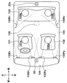
図1ないし図8は本発明の第1実施形態を示したもので、図1は、車室内100の各空調ゾーン101a、102a、103a、103bの位置関係、および各空調ゾーン101a、102a、103a、103bに対する空調空気の吹出口の配置を示す模式図である。符号100Dr、100Pa、100Rrはそれぞれ運転席101の乗員(運転者)、助手席102の乗員、後席103の乗員の上半身に向かって空調空気を吹き出すフェイス吹出口であり、それぞれ運転席空調ゾーン101a、助手席空調ゾーン102a、後席空調ゾーン103a、103bに空調空気を吹き出すための吹出口である。なお、符号103aは後席空調ゾーンのうち運転席空調ゾーン101aの後方に位置する運転席後方空調ゾーンを示し、符号103bは後席空調ゾーンのうち助手席空調ゾーン102aの後方に位置する助手席後方空調ゾーンを示す。
【0025】
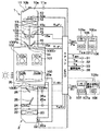
図2は、本実施形態の車両用空調装置の全体構成を示す全体構成図であり、この空調装置は、運転席空調ゾーンおよび助手席空調ゾーン(以下、前席空調ゾーンと呼ぶ)101a、102aをそれぞれ独立に空調するための前席用空調ユニット1と、運転席後方空調ゾーン103aおよび助手席後方空調ゾーン103bを同一の空調制御値で空調するための後席用空調ユニット2とから構成されている。前席用空調ユニット1は計器盤104内側に配置されており、後席用空調ユニット2は車室内100の最後方に配置されている。
【0026】
前席用空調ユニット1は車室内100に空気を送るダクト10を備え、このダクト10内に空気流れ上流から下流に向かって次に示す構成部品を順次配置している。すなわち、ダクト10に開口する内気導入口10aおよび外気導入口10bを開閉して内気モードおよび外気モードを切り替える内外気切替ドア11、車室内100に向かう空気流を発生させるブロア12、図示しない冷凍サイクルの冷媒により空気を冷却するエバポレータ13、空気を加熱するヒータコア14、車室内100に吹き出す空気の温度を調節するエアミックスドア15、前席空調ゾーン101a、102aへの吹出口モードを切り替える吹出口切換ドア16を備える。
【0027】
そして、ダクト10内のうちエバポレータ13の下流部分には仕切り板17が備えられており、これによりダクト10内は運転席側フェイス吹出口100Drに空気を導く運転席側通路10cと助手席側フェイス吹出口100Paに空気を導く助手席側通路10dとに仕切られている。そして、運転席側通路10c前述のエアミックスドア15および吹出口切換ドア16は、両通路10c、10dのそれぞれに設けられている。
【0028】
なお、図2では、フット吹出口、デフロスタ吹出口を省略しているが、運転席側および助手席側通路10c、10dのそれぞれに各吹出口が開口しており、図示しない吹出口切換ドアにより開閉されるようになっている。そして、吹出口モードには、周知のフェイスモード、デフロスタモード、フットモード、バイレベルモード、フットデフモード等がある。
【0029】
後席用空調ユニット2は車室内100に空気を送るダクト20を備え、このダクト20内に空気流れ上流から下流に向かって次に示す構成部品を順次配置している。すなわち、車室内100に向かう空気流を発生させるブロア22、図示しない冷凍サイクルの冷媒により空気を冷却するエバポレータ23、空気を加熱するヒータコア24、車室内100に吹き出す空気の温度を調節するエアミックスドア25、後席空調ゾーン103a、103bへの吹出口モードを切り替える吹出口切換ドア26を備える。
【0030】
なお、図2では、フット吹出口、デフロスタ吹出口を省略しているが、ダクト20には各吹出口が開口しており、図示しない吹出口切換ドアにより開閉されるようになっている。また、ダクト20内には内気導入口20aからの内気のみが導入され、常に内気循環モードとなる。また、吹出口モードには、周知のフェイスモード、フットモード、バイレベルモードがある。
【0031】
そして、以上の構成による前席用空調ユニット1および後席用空調ユニット2の作動は、共通の空調制御装置(以下、エアコンECUと呼ぶ)3により制御されるようになっている。
【0032】
エアコンECU3への入力信号には、外気温度センサ31により検出される車室外の外気温度Tam、冷却水温度センサ32により検出されるエンジンの冷却水温度Tw、日射センサ(日射検出手段)33により検出される運転席側および助手席側の日射量TsDr、TsPa、前席用および後席用の内気温度センサ34、35により検出される前席および後席空調ゾーン101a、102a、103a、103bの内気温度TrFr、TrRr、エバ後温度センサ36、37により検出される前席用および後席用のエバポレータ13、23直後の空気温度(以下、エバ後温度と呼ぶ)TeFr、TeRr、乗員が助手席102に着座(乗車)しているかを検出する助手席着座センサ38により検出される着座信号、運転席101、助手席102および後席103の各乗員が、運転席側、助手席側および後席空調ゾーン101a、102a、103a、103bの空気温度を希望する温度に設定するための温度設定手段(左右制御値設定手段)105、106、107からの設定温度TsetDr、TsetPa、TsetRr等が挙げられる。
【0033】
なお、日射センサ33は、フロントウインドウの内側にて車両左右方向の略中央部分に配置された周知の2D日射センサであり、運転席側からの日射量TsDrを検出するセンサと助手席側からの日射量TsPaを検出するセンサとを1体に構成したものである。
【0034】
また、本実施形態の着座センサは周知の赤外線センサを採用しており、着座センサは後席103のうち運転席側と助手席側のそれぞれを検出する2つの赤外線センサにより構成されている。また、温度設定手段105、106、107近傍には、各設定内容を表示するディスプレイ(設定温度表示手段)105a、106a、107aが備えられている。
【0035】
一方、エアコンECU3は上記入力信号に基づいて所定の演算処理を行い、下記の各アクチュエータに制御信号を出力する。そして、エアコンECU3からの出力信号には、内外気切換ドア11を駆動させるサーボモータ11a、ブロア12、22を駆動させる駆動モータ12a、22a、前述の冷凍サイクルの冷媒を吸入、圧縮、吐出するコンプレッサの電磁クラッチ、エバポレータ13、23の冷媒流れ上流側にて冷媒流れを断続する電磁弁、エアミックスドア15、25を駆動させるサーボモータ15a、25a、吹出口切換ドア16、26を駆動させるサーボモータ16a、26aの作動を制御するための信号等が挙げられる。
【0036】
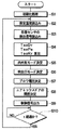
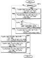
図3はエアコンECU3が実行するプログラムのフローチャートを示しており、以下にフローチャートの内容を説明する。
【0037】
先ず、データやフラグなどの初期化(リセット)を行う(ステップS1)。そして、温度設定手段105、106、107から設定温度TsetDr、TsetPa、TsetRrを読み込む(ステップS2)。そして、上述の各センサから、外気温度Tam、冷却水温度Tw、日射量TsDr、TsPa、内気温度TrFr、TrRr、エバ後温度TeFr、TeRr、助手席着座センサ38により検出される着座信号を読み込む(ステップS3)。
【0038】
次に、前席用空調ユニット1により運転席側および助手席側フェイス吹出口100Dr、100Paから吹き出される空調風の空調制御値である運転席目標吹出温度TaoDr、助手席目標吹出温度TaoPaを算出する。また、後席用空調ユニット2により吹出口100Rrから吹き出される空調風の後席目標吹出温度(空調制御値)TaoRrを算出する(ステップS4)。この算出方法は、図7のフローチャートを用いて後に詳述する。
【0039】
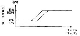
次に、上述のステップS4にて算出されたTaoDr、TaoPaに基づいて図4の特性図から前席用空調ユニット1の内外気モードを決定する(ステップS5)。なお、図4中、SW1は内外気切換ドア11の目標開度であり、本実施形態においては内気導入口10aを全閉し、外気導入口10bを全開する場合を目標開度SW1=100%とする。
【0040】
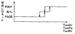
次に、上述のステップS4にて算出されたTaoDr、TaoPa、TaoRrに基づいて図5の特性図から前席用空調ユニット1の運転席側および助手席側の吹出口モードをそれぞれ決定するとともに、後席用空調ユニット2の吹出口内モードを決定する(ステップS6)。
【0041】
次に、上述のステップS4にて算出されたTaoDr、TaoPa、TaoRrに基づいて図6の特性図から前席用および後席用空調ユニット1、2のブロア12、22の駆動モータ12a、22aに印加されるブロア電圧(V)をそれぞれ決定して、ブロア12、22に所定の風量を生じさせる(ステップS7)。なお、前席用空調ユニット1の駆動モータ12aへのブロア電圧は、TaoDr、TaoPaに基づいて図6の特性図によりそれぞれ決定されたブロア電圧を平均化処理することにより得られている。
【0042】
次に、上述のステップS4にて算出されたTaoDr、TaoPaに基づいて、前席用空調ユニット1のエアミックスドア15の目標開度θDr、θPaを次の数1の式により算出する。また、後席用空調ユニット2のエアミックスドア25の目標開度θRrをTaoRrに基づいて数2の式により算出する(ステップS8)。
【0043】
【数1】
θ(i)={(Tao(i)−TeFr)/(Tw−TeFr)}×100(%)
但し、iはDrまたはPaである。
【0044】
【数2】
θRr={(TaoRr−TeRr)/(Tw−TeRr)}×100(%)
次に、上述のステップS4〜ステップS8にて決定または算出された空調制御状態となるように、前述の各種出力モータ等の作動を制御する信号を出力する(ステップS9)。そして、所定の制御周期時間(t)が経過したか否かを判定する(ステップS10)。この判定結果がYESの場合にはステップS2にリターンされ、その判定結果がNOの場合には制御周期時間(t)の経過を待つ。
【0045】
ここで、ステップS4では、図7のフローチャートに示すステップS410〜S480によりTaoDr、TaoPa、TaoRrを算出しており、以下に、図7を用いてこれらの算出方法を説明する。
【0046】
先ず、助手席着座センサ38の着座信号に基づいて、助手席102の乗員が不在か否かを判定する(ステップS410(判定手段))。そして、助手席102に乗員が乗車していると判定された場合には、ステップS420にて数3の式に基づいて後席目標吹出温度TaoRrを算出し、助手席102の乗員が不在であると判定された場合には、ステップS450にて数3の式に基づいて後席目標吹出温度TaoRrを算出する。
【0047】
【数3】
TaoRr=KsetRr・TsetRr−KrRr・TrRr−Kam・Tam−KsRr・Ts’+C+f(j)
但し、KsetRrは後席用温度設定ゲイン、KrRrは後席用内気温ゲイン、Kamは外気温ゲイン、KsRrは後席用日射ゲイン、Ts’は後述する日射量、Cは補正定数、f(j)は前席空調ゾーン101a、102aの空調状態に応じた補正ゲインを決定する(後に詳述する)補正関数であり、変数jはステップS410の判定結果に応じて変化する変数である。
【0048】
そして、数3の式のTs’は、ステップS420では運転席側日射量TsDrおよび助手席側日射量TsPaの平均値((TsDr+TsPa)/2)とされ、ステップS450では運転席側日射量TsDrとされている。これにより、助手席102の乗員が不在である場合には、運転席後方空調ゾーン103aの乗員が快適な温感を得られるように後席目標吹出温度TaoRrは日射補正される。
【0049】
また、補正関数f(j)による補正は、後席空調ゾーン103a、103bの空調状態が前席空調ゾーン101a、102aの空調状態から受ける影響を打ち消すための温度補正であり、補正関数f(j)は以下の数4の多項式によるものである。
【0050】
【数4】
f(j)=α・((TPAI+β)/(100+β))・(TsetRr−j)
但し、αは温度補正係数、TPAIは第1内外気補正係数、βは第2内外気補正係数である。
【0051】
そして、変数jは、ステップS420では後述のTsetDr’およびTsetPa’の平均値((TsetDr’+TsetPa’)/2)とされ、ステップS450ではTsetDr’とされている。これにより、後席目標吹出温度TaoRrは、助手席102の乗員が不在である場合には、運転席後方空調ゾーン103aの乗員が快適な温感を得られるように後席目標吹出温度TaoRrは温度補正される。
【0052】
ここで、TsetDr’とは、TsetDrの検出値(生値)に対する緩和処理(例えば時定数処理)により補正された値である。この緩和処理を具体的に説明すると、TsetDrの値が急激に変化した場合に、TsetDrの値を時間に対して指数関数的に変化させるようにする処理であり、TsetDrの急激な変化による空調状態の不安定化を防止するための処理である。なお、時定数τは、TsetDrの変化量に対してTsetDr’の変化量が63.2%の割合に到達するまでの時間(秒)であり、本実施形態では時定数τを30秒としている。
【0053】
ところで、前席空調ゾーン101a、102aの空調状態による後席空調ゾーン103a、103bの空調状態への影響は、前席の吹出口モードの状態によって異なる。特に、フェイスモード時に吹き出される空調風はその他のモード時の空調風に比べて後席空調ゾーン103a、103bの空調状態に与える影響が大きい。この点に着目し、前席用空調ユニット1の吹出口モードの状態に応じてαの値を変化させるようにしている。具体的には、フェイスモード(例えばα=5.0)、フットモード(例えばα=2.5)、フットデフモードおよびデフロスタモード(例えばα=1.0)、バイレベルモード(例えばα=0.75)の順にαの値を大きくしている。
【0054】
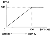
また、一般的に、外気モードの際には、車両前方から導入される外気が車両後方から排出されるようになっている。よって、内気モードの場合に比べて外気モードの場合の方が、前席空調ゾーン101a、102aの空調状態による後席空調ゾーン103a、103bの空調状態への影響が大きくなる。この点に着目し、内外気切換ドア11がSW1=0%である全内気モードからSW1=100%である全外気モードに近づくほどTPAIの値を大きくするようにしている。図8は内外気切換ドア11の目標開度SW1とTPAIの関係を示す特性図であり、この特性図に従ってTPAIの値を変化させている。
【0055】
また、βは、TPAIの補正関数f(j)に対する重みを決定する補正係数であり、本実施形態では実験値に基づいてβ=488としている。また、αおよびTPAIの算出においては、吹出口モードおよび目標開度SW1の変化に対して前述の緩和処理(例えば時定数処理)により補正して算出するようにしている。これにより、補正関数f(j)の急激な変化による空調状態の不安定化を防止するようにしている。
【0056】
次に、助手席102に乗員が乗車していると判定された場合には、ステップS430およびステップS440にて数5の式に基づいて運転席および助手席目標吹出温度TaoDr、TaoPaを算出する。
【0057】
【数5】
Tao(i)=Kset(i)・Tset(i)−KrFr・TrFr−Kam・Tam−Ks(i)・Ts(i)+C+K(i)
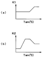
但し、iはDrまたはPa、Ksetは温度設定ゲイン、Krは内気温ゲイン、Kamは外気温ゲイン、Ksは日射ゲイン、Cは補正定数である。また、K(i)は運転席空調ゾーン101aおよび助手席空調ゾーン102a固有の補正ゲインである。具体的には、外気温度Tamに応じた補正係数K1およびK2を、実験により得られた図9(a)、(b)の特性図に従って決定し、数6および数7の式に基づいて補正ゲインK(i)を算出している。
【0058】
【数6】
KDr=K1(TsetDr−TsetPa)
【0059】
【数7】
KPa=K2(TsetPa−TsetDr)
一方、助手席102の乗員が不在であると判定された場合には、ステップS460にて数5の式に基づいて運転席目標吹出温度TaoDrを算出する。そして、ステップS470およびステップS480にて、助手席空調ゾーン102aに吹き出される空調空気が、助手席後方空調ゾーン103bに吹き出される空調空気と混合して助手席後方空調ゾーン103bを適正に日射補正するように、助手席目標吹出温度TaoPaを算出する。すなわち、助手席後方空調ゾーン103bの乗員が快適な温感を得られるように助手席目標吹出温度TaoPaを算出する。
【0060】
具体的には、運転席側日射量TsDrと助手席側日射量TsPaとの割合(日射の向き)に応じて助手席目標吹出温度TaoPaを算出しており、ステップS470にて、図7のステップS470中に示す特性図を用いて、運転席側日射量TsDrと助手席側日射量TsPaとの割合に基づいて日射ゲインKsPaを決定し、ステップS480にて、数5の式のKsPaにステップS470で決定された日射ゲインKsPaを代入する。なお、前記特性図は、運転席側からの日射量TsDrが多くなるほど日射ゲインKsPaを小さくし、助手席側からの日射量TsPaが多くなるほど日射ゲインKsPaを大きくするものである。
【0061】
また、ステップS480にて、数5の式のTset(i)にTsetRrの値を代入して、TsetRrに基づいて助手席目標吹出温度TaoPaを算出する。
【0062】
次に、上記構成による前席用空調ユニット1および後席用空調ユニット2の作動を簡単に説明する。
【0063】
初めに前席用空調ユニット1の作動を説明すると、ステップS5、S6、S7、S8による各決定に基づいて、内外気切換ドア11、運転席側および助手席側の各吹出口切換ドア16、ブロア12、運転席側および助手席側の各エアミックスドア15が駆動される。
【0064】
これにより、内気導入口10aおよび外気導入口10bからダクト10内に空気が導入される。ダクト10内を流れる空気は、エバポレータ13を通過する際に冷媒と熱交換して冷却される。ここで、エバ後温度TeFr、TeRrの検出値等に基づいてエアコンECU3によってコンプレッサの回転数を制御することにより、冷凍サイクル内を流れる冷媒の流量を制御して、エバポレータ13の冷却性能を調整している。エバポレータ13で冷却された空気は、ヒータコア14を通過する際にエンジン冷却水と熱交換して加熱される。そして、エアミックスドア15によってヒータコア14を通過する空気とヒータコア14を迂回する空気との割合が調節され、こうして所定の温度に左右独立して調整された空調空気が、運転席側および助手席側の各吹出口100Dr、100Paから吹き出される。
【0065】
次に後席用空調ユニット2の作動を説明すると、ステップS6、S7、S8による各決定に基づいて、各吹出口切換ドア26、ブロア22、エアミックスドア25が駆動される。そして、前席用空調ユニット1と同様の方法により調整された空調空気が後席側の吹出口100Rrから吹き出される。
【0066】
以上により、判定手段S410により助手席102の乗員が不在であると判定された場合において、運転席後方空調ゾーン103aの乗員が快適な温感を得られるように後席目標吹出温度TaoRrは日射補正されているので、運転席後方空調ゾーン103aの乗員については、後席側の吹出口100Rrのうち右側から吹き出される空調風により、偏日射の有無に関わらず、快適な温感を得ることができる。
【0067】
一方、助手席空調ゾーン102aに吹き出される空調空気が、助手席後方空調ゾーン103bに吹き出される空調空気と混合して助手席後方空調ゾーン103bを適正に日射補正するように、助手席目標吹出温度TaoPaは算出されているので、助手席後方空調ゾーン103bの乗員については、後席側の吹出口100Rrのうち左側から吹き出される空調風および助手席空調ゾーン102aに吹き出されて助手席後方空調ゾーン103bに向かって流れる空調風により、偏日射の有無に関わらず、快適な温感を得ることができる。
【0068】
よって、偏日射の有無に関わらず後席空調ゾーン103a、103bの左右の各乗員がともに快適な温感を得られるようにすることを、従来の空調装置の配風機構を用いることなく実現でき、空調装置の製造原価低減および大型化の抑制を図ることができる。
【0069】
(第2実施形態)
本実施形態では、助手席空調ゾーン102aの制御内容を設定可能な設定スイッチ(設定手段)108が、後席103近傍(例えば図1の一点鎖線に示す、センタコンソール後部の位置)に設置されている。この設定スイッチ108が操作されると、後席103の乗員が助手席空調ゾーン102aの制御内容を設定する助手席設定操作モードとなる。
【0070】
図10は、本実施形態を示すフローチャートであり、図3のステップS4に対応するTaoDr、TaoPaおよびTaoRrを算出するものである。
【0071】
ステップS415にて設定スイッチ108により助手席設定操作モードが選択されている場合には、第1実施形態と同様のステップS450、S460にて、後席目標吹出温度TaoRrおよび運転席目標吹出温度TaoDrを算出する。
【0072】
そして、ステップS490にて、第1実施形態の数5の式のTset(i)に、設定スイッチ108により設定される助手席空調ゾーン102aの設定温度TsetPaRrの値を代入して、TsetPaRrに基づいて助手席目標吹出温度TaoPaを算出する。
【0073】
一方、助手席設定操作モードが選択されていない場合には、第1実施形態と同様のステップS420、S430、S440にて各目標吹出温度TaoRr、TaoDr、TaoPaを算出する。
【0074】
これにより、助手席空調ゾーン102aの乗員が不在の場合には、助手席空調ゾーン102aに吹き出される空調空気が、助手席後方空調ゾーン103bに吹き出される空調空気と混合して助手席後方空調ゾーン103bを適正に日射補正するように、設定温度TsetPaRrを設定すれば、第1実施形態と同様に、助手席後方空調ゾーン103bの乗員については、後席側の吹出口100Rrのうち左側から吹き出される空調風および助手席空調ゾーン102aに吹き出されて助手席後方空調ゾーン103bに向かって流れる空調風により、偏日射の有無に関わらず、快適な温感を得ることができる。
【0075】
(第3実施形態)
本実施形態では、第1実施形態において、判定手段S410が乗員不在を判定した場合には、助手席空調ゾーン102aの吹出モードを、フェイス吹出口100Paから空調空気を吹き出すフェイス吹出モードにしている。これにより、助手席空調ゾーン102aに吹き出される空調空気が助手席後方空調ゾーン102aに流れ易くなる。よって、助手席空調ゾーン102aに吹き出される空調空気が、助手席後方空調ゾーン103bに吹き出される空調空気と混合して助手席後方空調ゾーン103bを適正に日射補正することを容易にできる。
【0076】
また、助手席側フェイス吹出口100Paに、吹き出し向きを変えるルーバ(風向可変手段)を備える空調装置においては、判定手段S410が乗員不在を判定した場合には、助手席側フェイス吹出口100Paからの空調空気が助手席102を避けて助手席後方空調ゾーン103bに流れるように、ルーバの向きを制御するようにすれば、助手席空調ゾーン102aに吹き出される空調空気が助手席後方空調ゾーン103bに、より一層流れ易くなり、好適である。
【0077】
また、判定手段S410が乗員不在を判定した場合には、助手席空調ゾーン102aに吹き出される空調空気の風量を多くするようにすれば、助手席空調ゾーン102aに吹き出される空調空気により助手席後方空調ゾーン103bの空調状態が影響を受ける度合を、より一層大きくでき、好適である。
【0078】
(第4実施形態)
本実施形態では、後席103近傍(例えば図1の一点鎖線位置)に、後席用空調装置2の作動を設定する操作手段を有する操作パネル(図示せず)を備え、この操作パネルに、後席空調ゾーン103a、103bの設定温度TsetRrを設定する温度設定手段107および第2実施形態の設定スイッチ108を配置している。これにより、後席の乗員による空調装置の操作性を良好にできる。
【0079】
ところで、第1実施形態において、判定手段S410が乗員不在を判定した場合には、助手席空調ゾーン102aに吹き出される空調空気は、助手席側の設定温度TsetPaと無関係に助手席目標吹出温度TaoPaが算出されるため、乗員に違和感を与えてしまう。
【0080】
そこで、助手席空調ゾーン102aに吹き出される空調空気により助手席後方空調ゾーン103bを空調制御するように助手席目標吹出温度TaoPaを算出している旨を、第1実施形態で述べたディスプレイ105a、106a、107aに表示する等して、乗員に報知するようにすれば、乗員に対する違和感を抑制できる。
【0081】
また、第1実施形態において、判定手段S410が乗員不在を判定した場合には、助手席設定温度TsetPaをディスプレイ105aに表示することを禁止するので、乗員に対する前述の違和感を抑制できる。
【0082】
(第5実施形態)
本実施形態では、第1実施形態において助手席空調ゾーン102aに吹き出される空調空気により助手席後方空調ゾーン103bを空調制御することを禁止可能な禁止手段を備える。この禁止手段は、判定手段S410の判定に関わらず、助手席目標吹出温度TaoPaをステップS440にて算出するようにするものである。これにより、判定手段S410が乗員不在を判定した際の助手席空調ゾーン102aに吹き出される空調空気の制御が、乗員の好みに合わない場合には、ステップS480による助手席目標吹出温度TaoPaの算出を禁止でき、好適である。
【0083】
(第6実施形態)
第1実施形態では着座センサとして赤外線センサを採用しているが、本発明はこれに限られるものではなく、超音波センサ、各座席102、103に備えられる圧力センサを採用してもよい。また、シートベルトを装着することにより着座信号を出力するようにしてもよい。また、各座席101、102、103の状態(例えば背もたれ部分の角度等)を乗員の好みに応じて設定するためのシートスイッチへの操作の有無を着座信号としてもよい。また、各温度設定手段105、106、107および優先設定スイッチ108による設定操作の有無を着座信号としてもよい。また、乗員の音声による音声信号を着座信号としてもよい。また、乗降用ドアの開閉による開閉信号を着座信号としてもよい。また、映像検出手段による乗員の映像の有無を着座信号としてもよい。
【0084】
(第7実施形態)
第1実施形態では、各目標吹出温度TaoRr、TaoDr、TaoPaを同一の日射センサ33の検出値TsDr、TsPaに基づいて日射補正するようにしているが、車室内100の後方側箇所(例えばセンタコンソール後部)に後席用の2D日射センサ33を追加して、後席目標吹出温度TaoRrを後席用2D日射センサ33の検出値TsDr、TsPaに基づいて日射補正するようにして、後席目標吹出温度TaoRrの日射補正の精度を高めるようにしてもよい。
【0085】
また、日射量検出手段33は2D日射センサに限られるものではなく、例えば、1D日射センサを車室内100の右側および左側にそれぞれ備えるようにしてもよい。また、日射量検出手段33による右側および左側からの日射量TsDr、TsPaの検出値は、車両用ナビゲーションシステムからの情報による日射の向きと、少なくとも1つの1D日射センサによる日射量とから推定される値であってもよい。
【0086】
(第8実施形態)
本実施形態では、太陽の車両に対する位置を検出する検出手段を備えており、太陽が車両の真上の位置から真横の位置になるにつれて、空調制御値TaoRrを日射補正する度合を大きくするようにしている。これにより、車両に対する日射角度の変化による乗員の受ける日射量の変化に応じて、空調制御値TaoRrを適切に日射補正することができる。
【0087】
(他の実施形態)
第1実施形態では、前後2つに区画された空調ゾーンを独立して空調する空調装置に本発明を適用しているが、前後方向に複数列のシートを有する車両の空調装置に採用されているように、前後方向に複数に区画された空調ゾーンを独立して空調する空調装置に本発明を適用してもよい。
【図面の簡単な説明】
【図1】本発明の第1実施形態における空調空気の吹出口の配置を示す模式図である。
【図2】第1実施形態における車両用空調装置の全体構成を示す全体構成図である。
【図3】第1実施形態におけるエアコンECUが実行するプログラムのフローチャートである。
【図4】第1実施形態におけるTaoと内外気モードとの関係を表す特性図である。
【図5】第1実施形態におけるTaoと吹出口モードとの関係を示す特性図である。
【図6】第1実施形態におけるTaoとブロア電圧との関係を示す特性図である。
【図7】図3のフローチャートの部分詳細を示すフローチャートである。
【図8】第1実施形態における内外気切換ドアの目標開度SW1と第2内外気補正係数との関係を示す特性図である。
【図9】(a)は、第1実施形態における補正係数K1と外気温度Tamとの関係を示す特性図であり、(b)は、補正係数K2と外気温度Tamとの関係を示す特性図である。
【図10】本発明の第2実施形態における目標吹出温度TaoDr、TaoPa、TaoRrの算出方法を示すフローチャートである。
【符号の説明】
100…車室内、101a…運転席空調ゾーン、
102a…助手席空調ゾーン、103a…運転席後方空調ゾーン、
103b…助手席後方空調ゾーン、108…設定スイッチ、
S410…判定手段、TaoPa…助手席目標吹出温度、
TaoRr…後席目標吹出温度。[0001]
BACKGROUND OF THE INVENTION
The present invention relates to a vehicle air conditioner capable of independently controlling air conditioning of front and rear air conditioning zones in a vehicle interior and independently controlling air conditioning of right and left air conditioning zones of a front air conditioning zone. is there.
[0002]
[Prior art]
Conventionally, Japanese Patent Application Laid-Open No. 5-193337 has proposed a vehicle air conditioner that controls the air conditioning of the left and right air conditioning zones of the rear seat at the same target blowing temperature. In this conventional apparatus, the rear seats are controlled even in the case of polarized solar radiation that receives solar radiation from one side in the left-right direction by controlling the distribution ratio of the conditioned air from the left and right air outlets according to the direction of solar radiation. Both passengers on the left and right sides of the vehicle can get a comfortable warm feeling.
[0003]
[Problems to be solved by the invention]
However, the prior art disclosed in the above publication requires a wind distribution mechanism for blowing different air volumes at the left and right outlets, resulting in a significant increase in manufacturing costs.
[0004]
In addition, this air distribution mechanism requires a large installation space, and in particular, when the air distribution mechanism is mounted on a rear seat air conditioner installed at the rear of the vehicle interior, the installation space is very small. Is difficult to mount.
[0005]
In view of the above points, the present invention realizes that both the left and right occupants in the rear air conditioning zone can obtain a comfortable warm feeling without using a wind distribution mechanism regardless of the presence or absence of polarized solar radiation. With the goal.
[0006]
[Means for Solving the Problems]
In order to achieve the above object, in the first aspect of the present invention, the air conditioning control of the front air conditioning zone (101a, 102a) and the rear air conditioning zone (103a, 103b) of the vehicle interior (100) is independently performed, In the vehicle air conditioner that independently controls the air conditioning of the right air conditioning zone (101a) and the left air conditioning zone (102a) of the front air conditioning zone, A face outlet (100 Dr, 100 Pa) that blows out conditioned air toward the upper body of the passengers in the front air conditioning zone (101a, 102a); Determination means for determining whether or not an occupant in at least one of the right and left air conditioning zones (101a, 102a) is absent (S410) When When the determination means (S410) determines the absence of an occupant, the conditioned air blown out to the vacant air conditioning zone (102a) and the vacant air conditioning zone (103a, 103b) in the absent air conditioning zone (103a, 103b) Air-conditioning control of the absent side rear air-conditioning zone (103b) located behind 102a) At the same time, the blowing mode of the air-conditioning zone (102a) on the absent side is changed to the face blowing mode in which conditioned air is blown out from the face outlet (100Pa). It is characterized by that.
[0007]
As a result, air-conditioning control is performed on the non-existing rear air-conditioning zone (103b) of the rear-side air-conditioning zones (103a, 103b) by the conditioned air blown to the non-existing air-conditioning zone (102a). The left and right of 103a, 103b) can be in different air conditioning states. Therefore, even in the case of uneven solar radiation, it is possible to achieve a comfortable warm feeling for each of the left and right passengers in the rear air conditioning zone without using a wind distribution mechanism.
[0008]
For example, when there is no occupant in the left air conditioning zone (102a) and solar radiation is received from the left side of the vehicle, the temperature of the conditioned air blown to the left and right of the rear air conditioning zones (103a, 103b) is set to the rear air conditioning. It controls so that the passenger | crew on the right side of a zone (103a, 103b) can obtain a comfortable warm feeling. And if the temperature of the conditioned air blown to the left air-conditioning zone (102a) is made lower than the temperature of the conditioned air blown to the rear-side air-conditioning zone (103a, 103b), the rear-side air-conditioning zone (103a, 103b) It can counteract the left occupant feeling hot due to solar radiation.
[0011]
By the way, when the absent side air-conditioning zone (102a) is in the face blowing mode, the conditioned air blown to the absent side air-conditioning zone (102a) is not present in the absent side rear air-conditioning zone (102a). 103b). Therefore, the degree to which the air conditioning state of the absent side air conditioning zone (103b) is affected by the conditioned air blown to the absent side air conditioning zone (102a) is determined when the absent side air conditioning zone (102a) is in the face blowing mode. Become the largest.
[0012]
Therefore, the
[0013]
[0014]
[0015]
By the way, when the determination means (S410) determines the absence of the occupant, the conditioned air blown to the absent air conditioning zone (102a) is irrelevant to the set contents such as the set temperature of the absent air conditioning zone (102a). Because it is controlled, the passenger feels uncomfortable.
[0016]
In contrast, the
[0017]
[0018]
Claim 7 The invention described in (1) is characterized by comprising prohibiting means capable of prohibiting the air conditioning control of the absent side rear air conditioning zone (103b) by the conditioned air blown out to the absent side air conditioning zone (102a).
[0019]
By the way, the control of the conditioned air blown to the absent air conditioning zone (102a) when the determination means (S410) determines the absence of an occupant increases the temperature difference between the right and left air conditioning zones (101a, 102a). In addition, there may be a case where noise increases with an increase in the air volume of the conditioned air blown out to the air conditioning zone (102a) on the absent side. Therefore, when the degree of increase in the temperature difference and noise does not meet the passenger's preference, the claim 7 It is preferable to use the prohibiting means described in 1.
[0020]
In the invention according to claim 9, The solar radiation detection means (33) for detecting the direction of solar radiation with respect to the vehicle is provided, and when the determination means (S410) determines the absence of an occupant, the absence according to the direction of solar radiation detected by the solar radiation detection means (33). The temperature (TaoPa) of the conditioned air blown into the air conditioning zone (102a) on the side It is characterized by that.
[0021]
This The conditioned air blown out to the absent side air conditioning zone (102a) is suitable because the temperature of the absent side air conditioning zone (102a) can be set to a temperature corresponding to uneven solar radiation. .
[0022]
In addition, the code | symbol in the bracket | parenthesis of each said means is an example which shows a corresponding relationship with the specific means as described in embodiment mentioned later.
[0023]
DETAILED DESCRIPTION OF THE INVENTION
(First embodiment)
In the present embodiment, the front seat (front side) air conditioning zone and the rear seat (rear side) air conditioning zone in the passenger compartment are independently controlled in air conditioning, and the driver seat side (right side) air conditioning zone and passenger seat of the front seat air conditioning zone The present invention is applied to a vehicle air conditioner that independently controls the air conditioning of the side (left side) air conditioning zone. In the present embodiment, since a right-hand drive vehicle will be described, the right side of the front seat of the vehicle in the passenger compartment is the driver seat side, and the left side of the front seat of the vehicle in the passenger compartment is the passenger seat side.
[0024]
1 to 8 show a first embodiment of the present invention. FIG. 1 shows the positional relationship between the air-
[0025]
FIG. 2 is an overall configuration diagram showing the overall configuration of the vehicle air conditioner according to the present embodiment. The air conditioner includes a driver's seat air conditioning zone and a passenger seat air conditioning zone (hereinafter referred to as front seat air conditioning zone) 101a, 102a. The
[0026]
The front seat
[0027]
A
[0028]
In FIG. 2, the foot outlet and the defroster outlet are omitted, but each outlet is opened in each of the driver's seat side and the passenger's
[0029]
The rear seat
[0030]
In FIG. 2, the foot outlet and the defroster outlet are omitted, but each outlet is opened in the
[0031]
The operations of the front seat
[0032]
The input signal to the
[0033]
The
[0034]
The seating sensor of the present embodiment employs a known infrared sensor, and the seating sensor includes two infrared sensors that detect the driver seat side and the passenger seat side of the
[0035]
On the other hand, the
[0036]
FIG. 3 shows a flowchart of a program executed by the
[0037]
First, initialization (reset) of data, flags, etc. is performed (step S1). Then, the set temperatures TsetDr, TsetPa, and TsetRr are read from the temperature setting means 105, 106, and 107 (step S2). Then, the outside air temperature Tam, the cooling water temperature Tw, the solar radiation amount TsDr, TsPa, the inside air temperature TrFr, TrRr, the post-evaporation temperature TeFr, TeRr, and the seating signal detected by the
[0038]
Next, the driver's seat target blowing temperature TaoDr and the passenger's seat target blowing temperature TaoPa, which are air conditioning control values of the conditioned air blown out from the driver's seat and passenger's side face outlets 100Dr and 100Pa by the front seat
[0039]
Next, based on TaoDr and TaoPa calculated in step S4 described above, the inside / outside air mode of the front seat
[0040]
Next, on the basis of TaoDr, TaoPa, TaoRr calculated in step S4 described above, from the characteristic diagram of FIG. The air outlet mode of the rear seat
[0041]
Next, based on the TaoDr, TaoPa, and TaoRr calculated in step S4 described above, the
[0042]
Next, based on TaoDr and TaoPa calculated in step S4 described above, target opening degrees θDr and θPa of the
[0043]
[Expression 1]
θ (i) = {(Tao (i) −TeFr) / (Tw−TeFr)} × 100 (%)
However, i is Dr or Pa.
[0044]
[Expression 2]
θRr = {(TaoRr−TeRr) / (Tw−TeRr)} × 100 (%)
Next, a signal for controlling the operation of the above-described various output motors is output so that the air-conditioning control state determined or calculated in Steps S4 to S8 is performed (Step S9). Then, it is determined whether or not a predetermined control cycle time (t) has elapsed (step S10). If the determination result is YES, the process returns to step S2, and if the determination result is NO, the control cycle time (t) is awaited.
[0045]
Here, in step S4, TaoDr, TaoPa, and TaoRr are calculated in steps S410 to S480 shown in the flowchart of FIG. 7, and these calculation methods will be described below with reference to FIG.
[0046]
First, based on the seating signal of the passenger
[0047]
[Equation 3]
TaoRr = KsetRr · TsetRr−KrRr · TrRr−Kam · Tam−KsRr · Ts ′ + C + f (j)
Where KsetRr is the rear seat temperature setting gain, KrRr is the rear seat inner air temperature gain, Kam is the outer air temperature gain, KsRr is the rear seat solar radiation gain, Ts' is the solar radiation amount described later, C is a correction constant, and f (j ) Is a correction function that determines a correction gain according to the air-conditioning state of the front seat air-
[0048]
In step S420, Ts ′ in
[0049]
The correction by the correction function f (j) is a temperature correction for canceling the influence of the air conditioning state of the rear seat
[0050]
[Expression 4]
f (j) = α · ((TPAI + β) / (100 + β)) · (TsetRr−j)
However, α is a temperature correction coefficient, TPAI is a first inside / outside air correction coefficient, and β is a second inside / outside air correction coefficient.
[0051]
The variable j is an average value of TsetDr ′ and TsetPa ′ ((TsetDr ′ + TsetPa ′) / 2), which will be described later, in step S420, and TsetDr ′ in step S450. As a result, the rear seat target outlet temperature TaoRr is equal to the temperature of the rear seat target outlet temperature TaoRr so that when the passenger in the
[0052]
Here, TsetDr ′ is a value corrected by a relaxation process (for example, a time constant process) on the detected value (raw value) of TsetDr. This mitigation process will be specifically described. This process is to change the value of TsetDr exponentially with respect to time when the value of TsetDr changes abruptly, and the air conditioning state due to the rapid change of TsetDr. It is a process for preventing destabilization of the. The time constant τ is the time (seconds) until the change amount of TsetDr ′ reaches 63.2% of the change amount of TsetDr. In this embodiment, the time constant τ is 30 seconds. .
[0053]
By the way, the influence of the air conditioning state of the front seat
[0054]
In general, in the outside air mode, outside air introduced from the front of the vehicle is discharged from the rear of the vehicle. Therefore, in the case of the outside air mode, the influence of the air conditioning state of the front seat
[0055]
Β is a correction coefficient for determining a weight for the correction function f (j) of TPAI. In this embodiment, β = 488 based on experimental values. Moreover, in calculating α and TPAI, the change in the outlet mode and the target opening degree SW1 is corrected and calculated by the above-described relaxation processing (for example, time constant processing). This prevents instability of the air conditioning state due to a sudden change in the correction function f (j).
[0056]
Next, when it is determined that an occupant is on the
[0057]
[Equation 5]
Tao (i) = Kset (i) .Tset (i) -KrFr.TrFr-Kam.Tam-Ks (i) .Ts (i) + C + K (i)
However, i is Dr or Pa, Kset is a temperature setting gain, Kr is an inside air temperature gain, Kam is an outside air temperature gain, Ks is a solar radiation gain, and C is a correction constant. K (i) is a correction gain unique to the driver's seat
[0058]
[Formula 6]
KDr = K1 (TsetDr-TsetPa)
[0059]
[Expression 7]
KPa = K2 (TsetPa-TsetDr)
On the other hand, if it is determined that no passenger is present in the
[0060]
Specifically, the passenger seat target blowing temperature TaoPa is calculated according to the ratio (direction of solar radiation) between the driver seat side solar radiation amount TsDr and the passenger seat side solar radiation amount TsPa. In step S470, the step of FIG. Using the characteristic diagram shown in S470, the solar radiation gain KsPa is determined based on the ratio between the driver-seat-side solar radiation amount TsDr and the passenger-seat-side solar radiation amount TsPa, and in step S480, the KsPa in the
[0061]
In step S480, the value of TsetRr is substituted into Tset (i) in
[0062]
Next, the operation of the front seat
[0063]
First, the operation of the
[0064]
Thereby, air is introduced into the
[0065]
Next, the operation of the rear seat
[0066]
As described above, when the determination means S410 determines that the passenger in the
[0067]
On the other hand, the conditioned air blown to the passenger seat air-
[0068]
Therefore, it can be realized without using the air distribution mechanism of the conventional air conditioner that both the left and right occupants of the rear seat
[0069]
(Second Embodiment)
In the present embodiment, a setting switch (setting means) 108 capable of setting the control contents of the passenger seat
[0070]
FIG. 10 is a flowchart showing this embodiment, and calculates TaoDr, TaoPa, and TaoRr corresponding to step S4 of FIG.
[0071]
When the passenger seat setting operation mode is selected by the setting
[0072]
In step S490, the value of the set temperature TsetPaRr of the passenger seat
[0073]
On the other hand, when the passenger seat setting operation mode is not selected, the target blowing temperatures TaoRr, TaoDr, TaoPa are calculated in steps S420, S430, and S440 similar to the first embodiment.
[0074]
As a result, when there is no passenger in the passenger seat
[0075]
(Third embodiment)
In the present embodiment, in the first embodiment, when the determination unit S410 determines the absence of an occupant, the blowing mode of the passenger seat
[0076]
Further, in an air conditioner provided with a louver (wind direction changing means) for changing the blowing direction at the passenger seat side face outlet 100Pa, when the determination means S410 determines the absence of an occupant, the passenger seat side face outlet 100Pa If the direction of the louver is controlled so that the conditioned air flows to the passenger seat rear
[0077]
Further, if the determination means S410 determines the absence of an occupant, if the air volume of the conditioned air blown to the passenger seat
[0078]
(Fourth embodiment)
In the present embodiment, an operation panel (not shown) having operation means for setting the operation of the rear
[0079]
By the way, in 1st Embodiment, when determination means S410 determines a passenger | crew absence, the air-conditioning air blown off to the passenger-seat air-
[0080]
Therefore, the
[0081]
Further, in the first embodiment, when the determination unit S410 determines that the passenger is absent, the passenger seat set temperature TsetPa is prohibited from being displayed on the
[0082]
(Fifth embodiment)
In the present embodiment, there is provided prohibiting means capable of prohibiting the air conditioning control of the passenger seat rear
[0083]
(Sixth embodiment)
In the first embodiment, an infrared sensor is employed as the seating sensor, but the present invention is not limited to this, and an ultrasonic sensor and a pressure sensor provided in each of the
[0084]
(Seventh embodiment)
In the first embodiment, the target blowing temperatures TaoRr, TaoDr, and TaoPa are corrected for solar radiation based on the detected values TsDr and TsPa of the same
[0085]
Moreover, the solar radiation amount detection means 33 is not restricted to a 2D solar radiation sensor, For example, you may make it provide a 1D solar radiation sensor in the right side and the left side of the
[0086]
(Eighth embodiment)
In the present embodiment, a detection means for detecting the position of the sun with respect to the vehicle is provided, and the degree of solar radiation correction of the air conditioning control value TaoRr is increased as the sun changes from a position directly above the vehicle to a position directly beside. ing. Thereby, according to the change of the solar radiation amount which a passenger | crew receives by the change of the solar radiation angle with respect to a vehicle, the air-conditioning control value TaoRr can be appropriately solar-corrected.
[0087]
(Other embodiments)
In the first embodiment, the present invention is applied to an air conditioner that independently air-conditions an air conditioning zone that is divided into two front and rear sections. However, the present invention is adopted in an air conditioner for a vehicle having a plurality of rows of seats in the front and rear direction. As described above, the present invention may be applied to an air conditioner that independently air-conditions a plurality of air-conditioning zones partitioned in the front-rear direction.
[Brief description of the drawings]
FIG. 1 is a schematic diagram showing the arrangement of air outlets for conditioned air in a first embodiment of the present invention.
FIG. 2 is an overall configuration diagram showing the overall configuration of the vehicle air conditioner in the first embodiment.
FIG. 3 is a flowchart of a program executed by the air conditioner ECU according to the first embodiment.
FIG. 4 is a characteristic diagram showing the relationship between Tao and the inside / outside air mode in the first embodiment.
FIG. 5 is a characteristic diagram showing a relationship between Tao and the outlet mode in the first embodiment.
FIG. 6 is a characteristic diagram showing a relationship between Tao and a blower voltage in the first embodiment.
FIG. 7 is a flowchart showing details of a part of the flowchart of FIG. 3;
FIG. 8 is a characteristic diagram showing a relationship between a target opening degree SW1 of the inside / outside air switching door and a second inside / outside air correction coefficient in the first embodiment.
9A is a characteristic diagram showing the relationship between the correction coefficient K1 and the outside air temperature Tam in the first embodiment, and FIG. 9B is a characteristic diagram showing the relationship between the correction coefficient K2 and the outside air temperature Tam. It is.
FIG. 10 is a flowchart showing a method for calculating target blowing temperatures TaoDr, TaoPa, TaoRr in the second embodiment of the present invention.
[Explanation of symbols]
100 ... passenger compartment, 101a ... driver's seat air conditioning zone,
102a ... Passenger seat air conditioning zone, 103a ... Driver seat rear air conditioning zone,
103b ... rear passenger seat air conditioning zone, 108 ... setting switch,
S410 ... determination means, TaoPa ... passenger seat target blowing temperature,
TaoRr: Rear seat target blowing temperature.
Claims (9)
前記前側空調ゾーン(101a、102a)の乗員の上半身に向けて空調空気を吹き出すフェイス吹出口(100Dr、100Pa)と、
前記右側および左側空調ゾーン(101a、102a)のうち少なくとも一方の空調ゾーンの乗員が、不在であるかを判定する判定手段(S410)をと備え、
前記判定手段(S410)が乗員不在を判定した場合に、不在側の空調ゾーン(102a)に吹き出される空調空気により、前記後側空調ゾーン(103a、103b)のうち前記不在側の空調ゾーン(102a)の後方に位置する不在側後方空調ゾーン(103b)を空調制御するとともに、前記不在側の空調ゾーン(102a)の吹出モードを、前記フェイス吹出口(100Pa)から空調空気を吹き出すフェイス吹出モードにするようになっていることを特徴とする車両用空調装置。The air conditioning control of the front air conditioning zone (101a, 102a) and the rear air conditioning zone (103a, 103b) in the vehicle interior (100) is independently performed, and the right air conditioning zone (101a) and the left air conditioning zone (101a) of the front air conditioning zone ( 102a) and a vehicle air conditioner that independently controls air conditioning,
A face outlet (100 Dr, 100 Pa) that blows out conditioned air toward the upper body of the passenger in the front air conditioning zone (101a, 102a);
Occupant of at least one of the air conditioning zone of said right and left air conditioning zone (101a, 102a) is provided with a determination means for determining whether or absent (S410),
When the determination means (S410) determines the absence of an occupant, the vacant air conditioning zone (103a, 103b) of the vacant air conditioning zone (103a, 103b) is blown into the vacant air conditioning zone (102a). Air-conditioning control of the absent side rear air conditioning zone (103b) located behind 102a), and the blowing mode of the absent side air conditioning zone (102a) is changed to a face blowing mode in which conditioned air is blown from the face outlet (100 Pa). vehicle air-conditioning apparatus characterized by being adapted to.
前記判定手段(S410)が乗員不在を判定した場合には、前記フェイス吹出口(100Pa)からの空調空気が助手席(102)を避けて前記不在側後方空調ゾーン(103b)に流れるように、風向可変手段を制御することを特徴とする請求項1に記載の車両用空調装置。Wind direction variable means for changing the blowing direction of the face outlet (100 Pa),
When the determination means (S410) determines the absence of an occupant, the conditioned air from the face outlet (100 Pa) avoids the passenger seat (102) and flows to the absent side air conditioning zone (103b). 2. The vehicle air conditioner according to claim 1 , wherein the wind direction varying means is controlled.
前記右側および左側空調ゾーン(101a、102a)のうち少なくとも一方の空調ゾーンの乗員が、不在であるかを判定する判定手段(S410)を備え、
前記判定手段(S410)が乗員不在を判定した場合に、不在側の空調ゾーン(102a)に吹き出される空調空気により、前記後側空調ゾーン(103a、103b)のうち前記不在側の空調ゾーン(102a)の後方に位置する不在側後方空調ゾーン(103b)を空調制御するとともに、前記不在側の空調ゾーン(102a)に吹き出される空調空気の風量を多くするようになっていることを特徴とする車両用空調装置。The air conditioning control of the front air conditioning zone (101a, 102a) and the rear air conditioning zone (103a, 103b) in the vehicle interior (100) is independently performed, and the right air conditioning zone (101a) and the left air conditioning zone (101a) of the front air conditioning zone ( 102a) and a vehicle air conditioner that independently controls air conditioning,
Judgment means (S410) for determining whether or not an occupant in at least one of the right and left air conditioning zones (101a, 102a) is absent,
When the determination means (S410) determines the absence of an occupant, the vacant air conditioning zone (103a, 103b) of the vacant air conditioning zone (103a, 103b) is blown into the vacant air conditioning zone (102a). The air-conditioning control is performed on the absent-side rear air conditioning zone (103b) located behind 102a), and the amount of conditioned air blown to the absent-side air-conditioning zone (102a) is increased. A vehicle air conditioner.
前記左側空調ゾーン(102a)の設定温度を表示する左側設定温度表示手段(105a)とを備え、
前記判定手段(S410)が乗員不在を判定した場合には、前記右側および左側設定温度表示手段(105a、106a)に、前記不在側の空調ゾーン(102a)の設定温度を表示することを禁止することを特徴とする請求項1ないし5のいずれか1つに記載の車両用空調装置。A right set temperature display means (106a) for displaying a set temperature of the right air conditioning zone (101a);
Left set temperature display means (105a) for displaying the set temperature of the left air conditioning zone (102a),
When the determination means (S410) determines that no occupant is present, it is prohibited to display the set temperature of the air conditioning zone (102a) on the absence side on the right and left set temperature display means (105a, 106a). The vehicular air conditioner according to any one of claims 1 to 5 .
前記右側空調ゾーン(101a)の設定温度を表示する右側設定温度表示手段(106a)と、
前記左側空調ゾーン(102a)の設定温度を表示する左側設定温度表示手段(105a)と、
前記右側および左側空調ゾーン(101a、102a)のうち少なくとも一方の空調ゾーンの乗員が、不在であるかを判定する判定手段(S410)とを備え、
前記判定手段(S410)が乗員不在を判定した場合に、不在側の空調ゾーン(102a)に吹き出される空調空気により、前記後側空調ゾーン(103a、103b)のうち前記不在側の空調ゾーン(102a)の後方に位置する不在側後方空調ゾーン(103b)を空調制御するとともに、前記右側および左側設定温度表示手段(105a、106a)に、前記不在側の空調ゾーン(102a)の設定温度を表示することを禁止するようになっていることを特徴とする車両用空調装置。The air conditioning control of the front air conditioning zone (101a, 102a) and the rear air conditioning zone (103a, 103b) in the vehicle interior (100) is independently performed, and the right air conditioning zone (101a) and the left air conditioning zone (101a) of the front air conditioning zone ( 102a) and a vehicle air conditioner that independently controls air conditioning,
A right set temperature display means (106a) for displaying a set temperature of the right air conditioning zone (101a);
A left set temperature display means (105a) for displaying a set temperature of the left air conditioning zone (102a);
Occupant of at least one of the air conditioning zone of said right and left air conditioning zone (101a, 102a) is, determining means for determining is absent (S410) and provided with,
When the determination means (S410) determines the absence of an occupant, the vacant air conditioning zone (103a, 103b) of the vacant air conditioning zone (103a, 103b) is blown into the vacant air conditioning zone (102a). Air-conditioning control of the absent side rear air-conditioning zone (103b) located behind 102a) and the set temperature of the absent-side air-conditioning zone (102a) are displayed on the right and left set temperature display means (105a, 106a). A vehicle air conditioner characterized in that it is prohibited to do so.
前記判定手段(S410)が乗員不在を判定した場合には、前記日射検出手段(33)により検出された日射の向きに応じて、前記不在側の空調ゾーン(102a)に吹き出される空調空気の吹出温度(TaoPa)を制御することを特徴とする請求項1ないし8のいずれか1つに記載の車両用空調装置。Solar radiation detecting means (33) for detecting the direction of solar radiation with respect to the vehicle;
When the determination means (S410) determines the absence of an occupant, according to the direction of solar radiation detected by the solar radiation detection means (33), the conditioned air blown to the absent air conditioning zone (102a) The vehicle air conditioner according to any one of claims 1 to 8, wherein the blowout temperature (TaoPa) is controlled.
Priority Applications (1)
| Application Number | Priority Date | Filing Date | Title |
|---|---|---|---|
| JP2001029973A JP4457501B2 (en) | 2001-02-06 | 2001-02-06 | Air conditioner for vehicles |
Applications Claiming Priority (1)
| Application Number | Priority Date | Filing Date | Title |
|---|---|---|---|
| JP2001029973A JP4457501B2 (en) | 2001-02-06 | 2001-02-06 | Air conditioner for vehicles |
Publications (2)
| Publication Number | Publication Date |
|---|---|
| JP2002234328A JP2002234328A (en) | 2002-08-20 |
| JP4457501B2 true JP4457501B2 (en) | 2010-04-28 |
Family
ID=18894250
Family Applications (1)
| Application Number | Title | Priority Date | Filing Date |
|---|---|---|---|
| JP2001029973A Expired - Fee Related JP4457501B2 (en) | 2001-02-06 | 2001-02-06 | Air conditioner for vehicles |
Country Status (1)
| Country | Link |
|---|---|
| JP (1) | JP4457501B2 (en) |
Families Citing this family (3)
| Publication number | Priority date | Publication date | Assignee | Title |
|---|---|---|---|---|
| JP4524623B2 (en) * | 2005-01-18 | 2010-08-18 | 株式会社デンソー | Car seat temperature control device |
| KR20070082272A (en) * | 2006-02-16 | 2007-08-21 | 한라공조주식회사 | The automatic temperature control method of vehicle as passengers figure |
| JP7063106B2 (en) * | 2018-05-17 | 2022-05-09 | 株式会社デンソー | Solar intensity calculator and air conditioning system |
-
2001
- 2001-02-06 JP JP2001029973A patent/JP4457501B2/en not_active Expired - Fee Related
Also Published As
| Publication number | Publication date |
|---|---|
| JP2002234328A (en) | 2002-08-20 |
Similar Documents
| Publication | Publication Date | Title |
|---|---|---|
| JP3861793B2 (en) | Air conditioner for vehicles | |
| JP5128977B2 (en) | Air conditioner for automobile | |
| JP5477329B2 (en) | Air conditioner for vehicles | |
| WO2013088727A1 (en) | Vehicle air-conditioning device | |
| JPH0885333A (en) | Air conditioner for vehicle | |
| JP4311114B2 (en) | Air conditioner for vehicles | |
| JP3508485B2 (en) | Vehicle air conditioner | |
| JP2009292293A (en) | Air conditioning device for vehicle | |
| JP3480074B2 (en) | Air conditioner | |
| JP4457501B2 (en) | Air conditioner for vehicles | |
| JP4968042B2 (en) | Air conditioner for vehicles | |
| JP4812416B2 (en) | Air conditioner for vehicles | |
| JP2002234329A (en) | Vehicular air conditioner | |
| JP4450141B2 (en) | Air conditioner for vehicles | |
| JP3979075B2 (en) | Air conditioner for vehicles | |
| JPH10119542A (en) | Air conditioner for vehicle | |
| JP2001341514A (en) | Air conditioner | |
| JP3951698B2 (en) | Air conditioner for vehicles | |
| JP2002234327A (en) | Vehicular air conditioner | |
| JP3988525B2 (en) | Air conditioner for vehicles | |
| JP4458908B2 (en) | Air conditioner for vehicles | |
| JP2002012020A (en) | Air conditioner for open car | |
| JP4207708B2 (en) | Air conditioner for vehicles | |
| JP4207709B2 (en) | Air conditioner for vehicles | |
| JP4292939B2 (en) | Air conditioner for vehicles |
Legal Events
| Date | Code | Title | Description |
|---|---|---|---|
| A621 | Written request for application examination |
Free format text: JAPANESE INTERMEDIATE CODE: A621 Effective date: 20070223 |
|
| A977 | Report on retrieval |
Free format text: JAPANESE INTERMEDIATE CODE: A971007 Effective date: 20090917 |
|
| A131 | Notification of reasons for refusal |
Free format text: JAPANESE INTERMEDIATE CODE: A131 Effective date: 20090929 |
|
| A521 | Written amendment |
Free format text: JAPANESE INTERMEDIATE CODE: A523 Effective date: 20091105 |
|
| TRDD | Decision of grant or rejection written | ||
| A01 | Written decision to grant a patent or to grant a registration (utility model) |
Free format text: JAPANESE INTERMEDIATE CODE: A01 Effective date: 20100119 |
|
| A01 | Written decision to grant a patent or to grant a registration (utility model) |
Free format text: JAPANESE INTERMEDIATE CODE: A01 |
|
| A61 | First payment of annual fees (during grant procedure) |
Free format text: JAPANESE INTERMEDIATE CODE: A61 Effective date: 20100201 |
|
| FPAY | Renewal fee payment (event date is renewal date of database) |
Free format text: PAYMENT UNTIL: 20130219 Year of fee payment: 3 |
|
| FPAY | Renewal fee payment (event date is renewal date of database) |
Free format text: PAYMENT UNTIL: 20140219 Year of fee payment: 4 |
|
| R250 | Receipt of annual fees |
Free format text: JAPANESE INTERMEDIATE CODE: R250 |
|
| R250 | Receipt of annual fees |
Free format text: JAPANESE INTERMEDIATE CODE: R250 |
|
| LAPS | Cancellation because of no payment of annual fees |