JP4456998B2 - Speed sensor and ground vehicle speed sensor using the same - Google Patents
Speed sensor and ground vehicle speed sensor using the same Download PDFInfo
- Publication number
- JP4456998B2 JP4456998B2 JP2004378770A JP2004378770A JP4456998B2 JP 4456998 B2 JP4456998 B2 JP 4456998B2 JP 2004378770 A JP2004378770 A JP 2004378770A JP 2004378770 A JP2004378770 A JP 2004378770A JP 4456998 B2 JP4456998 B2 JP 4456998B2
- Authority
- JP
- Japan
- Prior art keywords
- speed sensor
- sensor
- antenna
- signal
- lens
- Prior art date
- Legal status (The legal status is an assumption and is not a legal conclusion. Google has not performed a legal analysis and makes no representation as to the accuracy of the status listed.)
- Active
Links
Images


Classifications
-
- H—ELECTRICITY
- H01—ELECTRIC ELEMENTS
- H01Q—ANTENNAS, i.e. RADIO AERIALS
- H01Q15/00—Devices for reflection, refraction, diffraction or polarisation of waves radiated from an antenna, e.g. quasi-optical devices
- H01Q15/02—Refracting or diffracting devices, e.g. lens, prism
- H01Q15/08—Refracting or diffracting devices, e.g. lens, prism formed of solid dielectric material
-
- G—PHYSICS
- G01—MEASURING; TESTING
- G01S—RADIO DIRECTION-FINDING; RADIO NAVIGATION; DETERMINING DISTANCE OR VELOCITY BY USE OF RADIO WAVES; LOCATING OR PRESENCE-DETECTING BY USE OF THE REFLECTION OR RERADIATION OF RADIO WAVES; ANALOGOUS ARRANGEMENTS USING OTHER WAVES
- G01S13/00—Systems using the reflection or reradiation of radio waves, e.g. radar systems; Analogous systems using reflection or reradiation of waves whose nature or wavelength is irrelevant or unspecified
- G01S13/02—Systems using reflection of radio waves, e.g. primary radar systems; Analogous systems
- G01S13/50—Systems of measurement based on relative movement of target
- G01S13/58—Velocity or trajectory determination systems; Sense-of-movement determination systems
- G01S13/60—Velocity or trajectory determination systems; Sense-of-movement determination systems wherein the transmitter and receiver are mounted on the moving object, e.g. for determining ground speed, drift angle, ground track
-
- G—PHYSICS
- G01—MEASURING; TESTING
- G01S—RADIO DIRECTION-FINDING; RADIO NAVIGATION; DETERMINING DISTANCE OR VELOCITY BY USE OF RADIO WAVES; LOCATING OR PRESENCE-DETECTING BY USE OF THE REFLECTION OR RERADIATION OF RADIO WAVES; ANALOGOUS ARRANGEMENTS USING OTHER WAVES
- G01S7/00—Details of systems according to groups G01S13/00, G01S15/00, G01S17/00
- G01S7/02—Details of systems according to groups G01S13/00, G01S15/00, G01S17/00 of systems according to group G01S13/00
- G01S7/03—Details of HF subsystems specially adapted therefor, e.g. common to transmitter and receiver
- G01S7/032—Constructional details for solid-state radar subsystems
-
- H—ELECTRICITY
- H01—ELECTRIC ELEMENTS
- H01Q—ANTENNAS, i.e. RADIO AERIALS
- H01Q19/00—Combinations of primary active antenna elements and units with secondary devices, e.g. with quasi-optical devices, for giving the antenna a desired directional characteristic
- H01Q19/06—Combinations of primary active antenna elements and units with secondary devices, e.g. with quasi-optical devices, for giving the antenna a desired directional characteristic using refracting or diffracting devices, e.g. lens
- H01Q19/062—Combinations of primary active antenna elements and units with secondary devices, e.g. with quasi-optical devices, for giving the antenna a desired directional characteristic using refracting or diffracting devices, e.g. lens for focusing
-
- G—PHYSICS
- G01—MEASURING; TESTING
- G01S—RADIO DIRECTION-FINDING; RADIO NAVIGATION; DETERMINING DISTANCE OR VELOCITY BY USE OF RADIO WAVES; LOCATING OR PRESENCE-DETECTING BY USE OF THE REFLECTION OR RERADIATION OF RADIO WAVES; ANALOGOUS ARRANGEMENTS USING OTHER WAVES
- G01S15/00—Systems using the reflection or reradiation of acoustic waves, e.g. sonar systems
- G01S15/02—Systems using the reflection or reradiation of acoustic waves, e.g. sonar systems using reflection of acoustic waves
- G01S15/50—Systems of measurement, based on relative movement of the target
- G01S15/58—Velocity or trajectory determination systems; Sense-of-movement determination systems
- G01S15/60—Velocity or trajectory determination systems; Sense-of-movement determination systems wherein the transmitter and receiver are mounted on the moving object, e.g. for determining ground speed, drift angle, ground track
Landscapes
- Engineering & Computer Science (AREA)
- Radar, Positioning & Navigation (AREA)
- Remote Sensing (AREA)
- Computer Networks & Wireless Communication (AREA)
- Physics & Mathematics (AREA)
- General Physics & Mathematics (AREA)
- Radar Systems Or Details Thereof (AREA)
Description
本発明は、電磁波を放射し、その電磁波が対象物により反射された反射信号を受信することで、対象物との相対速度を検出する速度センサに関し、特に、地面からの反射波を受信することで、地面との速度を検出する対地車速センサに関する。 The present invention relates to a speed sensor that detects a relative speed with respect to an object by radiating an electromagnetic wave and receiving a reflected signal reflected by the object, and in particular, receiving a reflected wave from the ground. Thus, the present invention relates to a ground vehicle speed sensor that detects the speed with the ground.
従来、対象物との相対速度を検出する速度センサとして、ドップラーセンサを利用したものが知られている。これは、電磁波や超音波を対象物に照射し、その反射波を受信することで、対象物との相対速度により生じるドップラー効果を利用するものである。その一例として、ドップラーセンサにより得られる対地車速値を、車両の重心回りの角速度に基づいて補正する車速検出装置があった(例えば、特許文献1参照)。 Conventionally, a sensor using a Doppler sensor is known as a speed sensor for detecting a relative speed with respect to an object. This utilizes the Doppler effect produced by the relative velocity with the object by irradiating the object with electromagnetic waves or ultrasonic waves and receiving the reflected waves. As an example, there has been a vehicle speed detection device that corrects a ground vehicle speed value obtained by a Doppler sensor based on an angular velocity around the center of gravity of the vehicle (see, for example, Patent Document 1).
また、従来、正確な車速を検出する目的で、超音波信号を超音波送信器から路面に送波し、その反射波を超音波受波器で受波して、その受波した信号を増幅し、その増幅信号から反射波周波数を得る車載用超音波計測装置において、超音波送波器から路面に送波する超音波を路面上で収束させるものがあった(例えば、特許文献2参照)。 Conventionally, for the purpose of detecting accurate vehicle speed, an ultrasonic signal is transmitted from the ultrasonic transmitter to the road surface, and the reflected wave is received by the ultrasonic receiver, and the received signal is amplified. However, in an in-vehicle ultrasonic measurement device that obtains a reflected wave frequency from the amplified signal, there is one that converges ultrasonic waves transmitted from an ultrasonic transmitter to a road surface on the road surface (see, for example, Patent Document 2). .
また、従来、レーダセンサとして、発振器や混合器等の能動回路とアンテナとを同一の半導体基板上に一体形成して単一または複数のMMIC(Monolithic Microwave Integrated Circuit)チップに構成し、そのMMICチップを樹脂パッケージで封止すると共に、アンテナの上方に誘電体レンズを装着し、レンズと樹脂パッケージとを金型により一体形成して低コスト化を図るものがあった(例えば、特許文献3参照)。 Conventionally, as a radar sensor, an active circuit such as an oscillator or a mixer and an antenna are integrally formed on the same semiconductor substrate to form a single or multiple MMIC (Monolithic Microwave Integrated Circuit) chip, and the MMIC chip. Is sealed with a resin package, a dielectric lens is mounted above the antenna, and the lens and the resin package are integrally formed by a mold to reduce the cost (for example, see Patent Document 3). .
本発明の発明者らは、本発明に先立って、速度センサおよびそれを対地車速センサに応用する技術について検討を行い、上記の従来技術文献を独自に抽出した。その結果、特許文献1および2に開示された技術には以下の問題点が存在することを、本発明の発明者らは独自に見出した。以下、その内容を詳細に説明する。
Prior to the present invention, the inventors of the present invention studied a speed sensor and a technique for applying it to an anti-ground vehicle speed sensor, and independently extracted the above-described prior art documents. As a result, the inventors of the present invention independently found that the techniques disclosed in
特に近年では、電磁波の中でもマイクロ波やミリ波を用いた速度センサが多く利用されている。この速度センサにおいて、特に地面との相対速度、すなわち、対地速度を測定するものがある。この速度センサは、例えば図2に示すように電磁波をある角度θをもって地面に照射し、地面からの反射波を受信することで対地速度を検出する。このとき、反射波の周波数は、ドップラー効果により照射した信号の周波数に対して次式[数1]で示す周波数fdだけシフトする。 Particularly in recent years, speed sensors using microwaves or millimeter waves among electromagnetic waves are often used. Among these speed sensors, there is a sensor that measures a relative speed with respect to the ground, that is, a ground speed. For example, as shown in FIG. 2, this speed sensor irradiates the ground with an electromagnetic wave at a certain angle θ and receives a reflected wave from the ground to detect the ground speed. At this time, the frequency of the reflected wave is shifted by the frequency fd represented by the following equation [Equation 1] with respect to the frequency of the signal irradiated by the Doppler effect.
![]()
![]()
上式において、f0は照射した信号の周波数、vは対地速度、cは光速を示している。したがって、この受信信号にFFT(Fast Fourier Transform:高速フーリエ変換)等の信号処理を施すことで受信信号の周波数成分からfdを算出し、さらに上記[数1]を用いてfdから対地速度vを算出することできる。 In the above equation, f0 is the frequency of the irradiated signal, v is the ground speed, and c is the speed of light. Therefore, the received signal is subjected to signal processing such as FFT (Fast Fourier Transform) to calculate fd from the frequency component of the received signal, and the ground speed v is calculated from fd using the above [Equation 1]. Can be calculated.
このようなドップラーセンサを利用した例として、特許文献1に開示されるドップラーセンサにより得られる対地車速値を、車両の重心回りの角速度に基づいて補正する車速検出装置が知られているが、以下の問題点が存在する。
As an example using such a Doppler sensor, a vehicle speed detection device that corrects the ground vehicle speed value obtained by the Doppler sensor disclosed in
実際に放射される電磁波には、図2に示すようなある程度の広がりが存在する。仮に、この広がりより、電磁波と地面とのなす角が最大θ1、最小θ2であったとする。このとき、ドップラー効果による反射波の周波数シフト量も、上記[数1]におけるθがθ2≦≦θ≦θ1の範囲内で変化する(ばらつく)ことに伴ってばらつきを持つことになる。このばらつきにより、最終的に検知される出力周波数は、この広がりの範囲内で不確定性を持つことになる。すなわち、これを元に算出される対地速度も、同様に不確定性を持つため、これが検知誤差となって出力されるという問題があった。 The electromagnetic wave actually radiated has a certain extent as shown in FIG. Suppose that the angle between the electromagnetic wave and the ground is the maximum θ1 and the minimum θ2 due to this spread. At this time, the frequency shift amount of the reflected wave due to the Doppler effect also varies as θ in [Formula 1] changes (varies) within the range of θ2 ≦≦ θ ≦ θ1. Due to this variation, the finally detected output frequency will have uncertainty within this range of spread. That is, since the ground speed calculated based on this also has uncertainty, there is a problem that this is output as a detection error.
上記特許文献2が開示する構成は、特に冠水路面を走行する車両が路面から巻き起こす水飛沫の影響で車速検知誤差が生じるのを防止するために、路面に送波する超音波を路面上で収束させ、路面上に超音波ビームスポットを形成するものである。この構成は、ほぼ鉛直方向に、路面にスポットを形成するような形状の超音波信号を送信し、路面により反射された超音波信号を受信する構成であるが、このとき、路面上のスポットを第二の超音波放射源とみなしたとき、この放射源からの超音波信号のサイドローブを受信することで速度検出するものである。しかし、この構成では、サイドローブからの信号を利用するため、最もエネルギーレベルの大きい中心方向成分の信号を利用できず、センサの感度が小さくなるという問題があった。また、同文献の図2に開示されるようにスポットから超音波受波器R1、R2へ向かう方向と車両の走行方向との成す角をθとしたとき、実際に計測される速度は、車両の対地走行速度vに対して、v×cosθとして計測されるため、速度分解能を向上させるためにはθを小さくする必要があるが、同文献が開示している構成では、サイドローブからの信号を受波して速度検知に利用することから、θがサイドローブの発生する角度に限定される。ここで、サイドローブの発生する角度がほぼ一定であることから、θもほぼ一定の値を取ることになり、可変にすることができない。例えば、比較的信号レベルの大きい第一サイドローブレベルを利用する場合、同文献の図2に開示されるように、その第一サイドローブが発生する角度にθが決まってしまう。そのため、十分に速度分解能を向上させることができないという問題があった。そればかりでなく、車高の異なる種々の車両に同文献の計測装置構成を適用しようとすると、第一サイドローブが発生する角度にθが決まってしまうため、車高すなわち超音波ビームスポットSPと超音波送波器UTとの距離の変化に応じて、UTを通る中心軸から超音波受波器R1、R2までの距離Lを変化させる必要がある。つまり、車高の変動に応じて計測装置自体のサイズを変更する必要が生じるという問題があった。
The configuration disclosed in
本発明の速度センサおよびそれを用いた対地車速センサの中から代表的なものの一例を概略的に示せば、以下のようになる。
まず、本発明の速度センサは、移動可能な物体に設置されるよう構成され、波動の性質を有する送信信号を放射し、その送信信号が対象物により反射することによって生じる反射信号を受信し、受信した反射信号と送信信号とから、上記の移動可能な物体と上記の対象物との間の相対速度を算出するのに必要な信号を生成して出力することを特徴とする。ここで、送信信号はビーム形状を成し、そのビーム形状は、対象物近傍でのビーム幅が速度センサの送信信号を放射するための放射口近傍でのビーム幅と比べてほぼ等しいかまたは小さくなるように形成される。さらに、送信信号は、移動可能な物体の対象物に対する相対速度方向と所定の角度を成す方向に放射口から放射され、その所定の角度は、0度より大きく90度より小さいかまたは90度より大きく180度より小さいかのいずれかの任意の角度である。
An example of a representative one of the speed sensor of the present invention and the ground vehicle speed sensor using the speed sensor is schematically shown as follows.
First, the speed sensor of the present invention is configured to be installed on a movable object, radiates a transmission signal having the nature of a wave, receives a reflection signal generated when the transmission signal is reflected by an object, A signal required for calculating a relative velocity between the movable object and the target object is generated from the received reflection signal and the transmission signal and output. Here, the transmission signal has a beam shape, and the beam shape is substantially equal to or smaller than the beam width in the vicinity of the object compared to the beam width in the vicinity of the radiation port for emitting the transmission signal of the speed sensor. Formed to be. Further, the transmission signal is radiated from the radiation port in a direction that forms a predetermined angle with the relative speed direction of the movable object with respect to the object, and the predetermined angle is greater than 0 degree and less than 90 degrees or greater than 90 degrees. Any angle that is greater than 180 degrees.
また、本発明の速度センサを用いた対地車速センサは、ビーム発生部から地面に向けて放射したビームの周波数と、ビームが地面にて反射することにより発生する反射ビームの周波数とから、地面上を走行し且つビーム発生部が取り付けられた車両の対地走行速度を検知するために以下の構成を有することを特徴とする。まず、ビームの形状は、地面近傍でのビーム幅がビーム発生部のビームを放射するための放射口近傍でのビーム幅と比べてほぼ等しいかまたは小さくなるように形成されている。さらに、そのビームは、車両の地面に対する相対速度方向と所定の角度を成す方向に放射口から放射される。ここで、所定の角度は、0度より大きく90度より小さいかまたは90度より大きく180度より小さいかのいずれかの任意の角度である。 The ground vehicle speed sensor using the speed sensor of the present invention is based on the frequency of the beam radiated from the beam generator toward the ground and the frequency of the reflected beam generated by the reflection of the beam on the ground. In order to detect the ground traveling speed of the vehicle traveling on the vehicle and having the beam generator attached thereto, the vehicle has the following configuration. First, the shape of the beam is formed so that the beam width in the vicinity of the ground is substantially equal to or smaller than the beam width in the vicinity of the radiation opening for emitting the beam of the beam generation unit. Further, the beam is emitted from the radiation port in a direction that forms a predetermined angle with the direction of the relative speed with respect to the ground of the vehicle. Here, the predetermined angle is any angle that is larger than 0 degree and smaller than 90 degrees or larger than 90 degrees and smaller than 180 degrees.
本発明によれば、放射する電磁波をビーム形状に形成して速度検知に用いるため、速度センサの検知誤差を低減できるという効果がある。 According to the present invention, since the radiating electromagnetic wave is formed into a beam shape and used for speed detection, there is an effect that the detection error of the speed sensor can be reduced.
本発明の速度センサおよびそれを用いた対地車速センサは、速度誤差の原因となる放射電磁波の広がりを抑制するために、センサから放射される電磁波の集光を行うと共に、所定のセンサ感度における最良の速度分解能を実現するために、センサの電磁波放射方向が車両の速度方向と所定の角度を成すように速度センサを配置することを特徴とする。 The speed sensor of the present invention and a ground vehicle speed sensor using the speed sensor condense the electromagnetic waves radiated from the sensor and suppress the spread of the radiated electromagnetic waves that cause a speed error, and at the best in a predetermined sensor sensitivity. In order to realize this speed resolution, the speed sensor is arranged such that the electromagnetic wave radiation direction of the sensor forms a predetermined angle with the speed direction of the vehicle.
一般的に、センサより放射される電磁波は、センサから遠方になるにしたがって、その広がりが大きくなる形状になるが、本発明では、センサ近傍での電磁波の広がりすなわちビーム幅に比して、測定する対象物の近傍での電磁波の広がりすなわちビーム幅がほぼ等しいかまたは小さくなる形状となるようにビームを形成する。こうすることで、対象物に照射される電波の面積を抑えることが可能となり、高精度な速度検知が可能となる。なお、地面との相対速度を計測する対地車速センサの場合、この対象物は地面に相当する。 In general, the electromagnetic wave radiated from the sensor has a shape in which the spread increases as the distance from the sensor increases. In the present invention, the electromagnetic wave is measured in comparison with the spread of the electromagnetic wave in the vicinity of the sensor, that is, the beam width. The beam is formed so that the spread of the electromagnetic wave in the vicinity of the target object, that is, the beam width is substantially equal or smaller. By doing so, it is possible to suppress the area of the radio wave irradiated to the object, and to detect the speed with high accuracy. In the case of a ground vehicle speed sensor that measures the relative speed with the ground, the object corresponds to the ground.
速度センサ1近傍と対象物近傍とでビーム幅がほぼ等しい場合は、図2に示した角度のばらつきが解消されることは明白であるが、対象物近傍のほうが速度センサ1近傍よりもビーム幅が小さい場合でも以下の理由により図2に示した角度のばらつきが解消される場合がある。図1において、放射した電磁波(ビーム)の対象物(地面6)との成す角度θは、厳密に言えばθ2≦θ≦θ1の範囲内で変化する(ばらつく)ことになるが、速度センサ1の送信信号(電磁波)放射口となる第二のレンズ2の中心点から送信信号(電磁波)が対象物(地面)に到達する点までの距離dが第二のレンズ2の径に比べて十分に大きくなるように速度センサ1を構成することが可能であれば、角度θ、θ1、θ2は、近似的にθ≒θ1≒θ2なる関係を満たす。よって、特にこのような条件が満たされる用途においては、ビーム形状を速度センサ1近傍と対象物近傍とでビーム幅がほぼ等しくなるように形成することが困難な場合であっても、対象物近傍のほうが速度センサ1近傍よりもビーム幅が小さくなるように速度センサ1を構成しさえすれば、図2に示した角度のばらつきの問題は解消されることになる。例えば、対地車速センサの場合、距離dは第二のレンズ2の直径の約10倍程度確保できるため、近似的にθ≒θ1≒θ2が成り立ち、角度θのばらつきを抑制することができ、以て、検知誤差の小さい高精度な速度検知が可能となる。
When the beam width is approximately equal between the vicinity of the
一般に電磁波を放射する手段としてアンテナが利用されるが、このアンテナから放射されるビームを形成するためには、大口径のアンテナを用いる、アンテナをアレー化する、パラボラアンテナを用いる、さらには、アンテナと誘電体レンズを組み合わせるなどの手法が用いられる。また、アンテナ形状としては、さまざまなものが存在し、いずれの形状でも基本的には本発明に適用可能であるが、近年では機器の小型化を目的としてマイクロストリップパッチアンテナなどの平面形状のアンテナが利用されることが多いことから、本発明においても、小型化を図る目的で平面形状のアンテナを用いるのが好適である。 In general, an antenna is used as a means for radiating electromagnetic waves. In order to form a beam radiated from the antenna, a large-diameter antenna is used, an antenna is arrayed, a parabolic antenna is used, and an antenna is used. And a method of combining a dielectric lens and the like. In addition, there are various antenna shapes, and any shape is basically applicable to the present invention. However, in recent years, a planar antenna such as a microstrip patch antenna is used for the purpose of downsizing the equipment. In many cases, it is preferable to use a planar antenna for the purpose of downsizing.
ところで、誘電体レンズと平面アンテナを組み合わせて使用する場合、アンテナには素子数の少ないアンテナを用いることが多い。特に、このアンテナをMMIC(Monolithic Microwave Integrated Circuit)上に構成する場合などは、MMICの面積がコストに比例するため、アンテナをアレー化することができないため、素子数の少ないアンテナを利用する必要がある。素子数の少ないアンテナを用いる場合、アンテナから放射される電磁波は十分なビーム合成ができないため、その放射電波の広がり角(放射角)は大きくなる。したがって、このビームの全電力範囲をカバーするためのレンズは、非常に径が大きなものとなる。一例として、アンテナに120度の放射角を持つ素子数が少ないアンテナを用いて、アンテナから5cmの距離に誘電体レンズを配置する場合、アンテナから放射される全電力範囲をカバーするためには、17cm以上の径を持つ誘電体レンズが必要となる。誘電体レンズの径は、誘電体レンズをアンテナから近い位置に配置することで小さくすることが可能であるが、以下に示すように、誘電体レンズの加工精度に対する要求が厳しくなるというトレードオフが存在する。 By the way, when a dielectric lens and a planar antenna are used in combination, an antenna having a small number of elements is often used as the antenna. In particular, when this antenna is configured on a MMIC (Monolithic Microwave Integrated Circuit), the area of the MMIC is proportional to the cost, and the antenna cannot be arrayed. Therefore, it is necessary to use an antenna with a small number of elements. is there. When an antenna with a small number of elements is used, electromagnetic waves radiated from the antenna cannot be combined sufficiently, and the spread angle (radiation angle) of the radiated radio wave becomes large. Therefore, the lens for covering the entire power range of this beam has a very large diameter. As an example, when a dielectric lens is arranged at a distance of 5 cm from an antenna using an antenna having a radiation angle of 120 degrees and a small number of elements, to cover the entire power range radiated from the antenna, A dielectric lens having a diameter of 17 cm or more is required. The diameter of the dielectric lens can be reduced by disposing the dielectric lens at a position close to the antenna. However, as shown below, there is a trade-off that requirements for processing accuracy of the dielectric lens become severe. Exists.
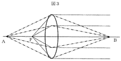
図3に示すようなレンズの焦点Fと結像点A、Bに関する光学的な一次近似では、一般に次式[数2]で表される。 In the first-order optical approximation with respect to the focal point F of the lens and the image formation points A and B as shown in FIG. 3, it is generally expressed by the following equation [Formula 2].
![]()
![]()
誘電体レンズの加工誤差によりFが変化した時の結像点Bの変化を調べるために、上記[数2]を微分して次式[数3]が得られる。 In order to examine the change of the image forming point B when F changes due to the processing error of the dielectric lens, the following [Expression 3] is obtained by differentiating the above [Expression 2].

対地車速センサでは、Aは電磁波を放射する等価的な点光源の位置、Bは対象物付近、すなわち、地面付近での結像点の位置、Fはレンズの形状で決まる焦点に相当する。数式3は、点光源の位置Aがレンズの焦点Fに接近するほど、Fの変動に対するBの変動が大きくなることを意味する。Fはレンズの形状できまる定数であるから、Fをばらつきなく製造するためには、レンズの加工精度を厳しくする必要がある。また、結像点Bが無限大とならないようにするためには、F<Aである必要がある。したがって、点光源Aとレンズとの距離は長いことが望ましい。
In the ground vehicle speed sensor, A corresponds to the position of an equivalent point light source that emits electromagnetic waves, B corresponds to the position of the imaging point near the object, that is, near the ground, and F corresponds to the focal point determined by the shape of the lens.
本発明は、上記の問題を、複数のレンズ(特に電磁波による場合は誘電体レンズ)を用いることで解決する。すなわち、第一のレンズをアンテナ近傍に配置する。この第一のレンズは、ビームの放射角を小さくするが、依然として結像点は無限遠点にある。そこで、さらに第二のレンズ2を配置することで、結像点Bが任意の位置になるように集光を行う。このとき、第一のレンズによりビームの放射角は狭められているため、第二のレンズ2をある程度の距離まで離しても、レンズの径は小さいままで全電力範囲をカバーすることが可能となる。また、第一のレンズはアンテナからのビームの放射角を小さくするために利用されており、結像点を決めるのは第二のレンズ2であるため、アンテナ近傍に存在する第一のレンズの加工精度は結像点に大きく影響しない。
The present invention solves the above problem by using a plurality of lenses (particularly, dielectric lenses in the case of electromagnetic waves). That is, the first lens is disposed near the antenna. This first lens reduces the radiation angle of the beam, but the image point is still at infinity. Therefore, the
一例として、第一のレンズによりビーム放射角が30度まで狭めることができたとして、第二のレンズ2を等価的な点光源の位置から5cmの距離に配置した場合、そのレンズの径は4cm程度で十分である。
As an example, assuming that the beam emission angle can be narrowed to 30 degrees by the first lens, when the
なお、上記の説明では2個のレンズを用いた場合で説明したが、これを3個以上の複数個用いても、少なくとも同等の効果が得られることは言うまでもない。また、同様に、素子数の少ない低素子アンテナと複数のレンズとを用いて電磁波をビーム形状に形成する例を用いて説明したが、これをアレーアンテナ、大口径のアンテナ、パラボラアンテナ、または、1個または複数の誘電体レンズ、さらには、これらの組合せにより同等ビーム形状が得られ場合、少なくとも同等の効果が得られることは言うまでもない。 In the above description, the case where two lenses are used has been described, but it goes without saying that at least the same effect can be obtained even if three or more lenses are used. In addition, similarly, an example of forming an electromagnetic wave in a beam shape using a low-element antenna with a small number of elements and a plurality of lenses has been described, but this is an array antenna, a large-diameter antenna, a parabolic antenna, or Needless to say, when an equivalent beam shape is obtained by one or a plurality of dielectric lenses, or a combination thereof, at least the same effect can be obtained.
地面との相対速度を検知する対地車速センサの場合において、Aは電磁波を放射する等価的な点光源の位置、Bは地面近傍での結像点に相当する。速度検知誤差を低減するために、最も効果的なのはBが地面と一致する場合である。しかし、センサから地面までの距離は車種よって異なるため、車種に応じて最適な値を設定する必要がある。この場合、レンズの形状を変更しなくても、Aの値を調整することで上記[数2]よりBの値は変更することが可能である。そこで、速度センサにAの値を調整する機構を持たせることで、車種に応じた最適なBを設定することが可能となる。例えば、上記で説明した2個のレンズを用いる場合では、第二のレンズ2の位置と点光源の位置とを調整することでAを変更することが可能である。すなわち、第二のレンズ2の取付位置を調整する機構を持たせることで実現可能である。さらに、車高を測定する車高センサを具備することで、その出力信号を元に、第二のレンズ2の取付位置を自動調整する機構を設置することで、人手による調整工程を省略することが可能である。なお、本発明の対地車速センサはドップラーセンサであるため、レーダの原理を応用することで対地車速センサに距離検知性能を持たせることが可能である。したがって、対地車速センサ自体に車高検知機能を持たせることも可能である。
In the case of a ground vehicle speed sensor that detects a relative speed with respect to the ground, A corresponds to the position of an equivalent point light source that emits electromagnetic waves, and B corresponds to an imaging point near the ground. In order to reduce the speed detection error, it is most effective when B coincides with the ground. However, since the distance from the sensor to the ground varies depending on the vehicle type, it is necessary to set an optimum value according to the vehicle type. In this case, even if the shape of the lens is not changed, the value B can be changed from the above [Equation 2] by adjusting the value A. Therefore, by providing a mechanism for adjusting the value of A to the speed sensor, it becomes possible to set an optimum B according to the vehicle type. For example, in the case of using the two lenses described above, A can be changed by adjusting the position of the
ドップラーセンサは、送信する信号を生成するための発振器、受信した信号を局部信号と混合して低周波信号を生成するための混合器などの回路素子と、送信信号を放射するための送信アンテナ、反射信号(反射波)を受信するための受信アンテナなどで構成される。また、必要に応じて増幅器などの回路素子が追加される。これらの回路素子は、通常、個別部品を組み合わせたHIC(Hybrid Integrated Circuit)やMMICで構成されるが、近年では、低コスト化を目的として、特にMMICがよく利用される。 The Doppler sensor is an oscillator for generating a signal to be transmitted, a circuit element such as a mixer for mixing a received signal with a local signal to generate a low frequency signal, a transmitting antenna for radiating a transmission signal, It is composed of a receiving antenna for receiving a reflected signal (reflected wave). Further, circuit elements such as amplifiers are added as necessary. These circuit elements are usually composed of an HIC (Hybrid Integrated Circuit) or an MMIC in which individual components are combined. In recent years, however, the MMIC is often used for the purpose of reducing the cost.
さらに、アンテナ素子をマイクロストリップアンテナのような平面回路として構成することで、アンテナ素子もMMIC上に構成することが可能となる。さらに、全ての必要な高周波回路と送受信アンテナとをモノリシックに形成することで、アンテナを介して送受信される電磁波以外の高周波信号は、MMICより外部に伝送する必要がなくなるため、簡易な実装方法が利用可能となる。簡易な実装方法の一例として、汎用ICで利用されている樹脂モールドパッケージなどを用いてもよい。また、前述のように、第一のレンズはアンテナ近傍に設けることが可能であり、パッケージ上に直接配置することも可能である。ICのパッケージとして樹脂モールドパッケージのような非金属製のパッケージを用いた場合、このレンズをパッケージと同一の材質で形成することにより、大量生産時は、金型による一体形成が可能となり低コスト化を図ることができる。 Furthermore, by configuring the antenna element as a planar circuit such as a microstrip antenna, the antenna element can also be configured on the MMIC. Furthermore, since all necessary high-frequency circuits and transmission / reception antennas are monolithically formed, high-frequency signals other than electromagnetic waves transmitted / received via the antennas need not be transmitted to the outside from the MMIC. Be available. As an example of a simple mounting method, a resin mold package used in a general-purpose IC may be used. Further, as described above, the first lens can be provided in the vicinity of the antenna, and can also be arranged directly on the package. When a non-metallic package such as a resin mold package is used as the IC package, this lens can be made of the same material as the package, so that it can be integrally formed with a mold during mass production, reducing costs. Can be achieved.
なお、以上の説明において、マイクロ波やミリ波などの高周波の電磁波を用いた速度センサ構成について説明したが、これを超音波や光を用いる速度センサ構成に置換した場合においても、少なくとも同等の効果が得られることは言うまでもない。
また、本発明の速度センサおよびそれを用いた対地車速センサが放射する電磁波のビーム形状は、センサ近傍でのビーム幅に対して地面近傍でのビーム幅が小さくなるビーム形状であれば種々の形状のものを適用可能であり、そのいずれのビーム形状を形成する場合にも、上記の装置構成は有効である。
In the above description, the speed sensor configuration using high-frequency electromagnetic waves such as microwaves and millimeter waves has been described. However, even when this is replaced with a speed sensor configuration using ultrasonic waves or light, at least the same effect can be obtained. It goes without saying that can be obtained.
The beam shape of the electromagnetic wave radiated by the speed sensor of the present invention and the ground speed sensor using the same may be various shapes as long as the beam width near the ground is smaller than the beam width near the sensor. The above-described apparatus configuration is effective when any of the beam shapes is formed.
以下、本発明の速度センサおよびそれを用いた対地車速センサのいくつかの実施例を、図面を参照しながら詳細に説明する。なお、これらの実施例の間で共通の部分は、同一の参照符号で指示されている。 Hereinafter, some embodiments of the speed sensor of the present invention and the ground vehicle speed sensor using the speed sensor will be described in detail with reference to the drawings. It should be noted that portions common to these embodiments are indicated by the same reference numerals.
図1および図15は、本発明の速度センサの第1の実施例であり、図15は本発明の速度センサを用いた対地車速センサが取り付けられた車両の概観図を示し、図1は本発明の速度センサから放射される電磁波の形状を示す。本発明の速度センサが対地車速センサとして利用される場合、速度センサ1は、車体5の下面、前面、あるいは後面などに取り付けられ、電磁波は対象物すなわち地面6に対して照射される。ここで、図15におけるvは車両5の速度、hは車両5の車高すなわち対地車速センサ1の取付位置の高さ、dは対地車速センサ1の電磁波放射口から地面6までの距離、θは対地速度vの方向と電磁波放射方向との成す角度である。図1におけるセンサ回路部3では、地面6に照射するための電磁波を生成し、送信アンテナから放射する。さらに、地面6からの反射波は受信アンテナにより受信され、混合器により局部信号と混合することで、相対速度の算出に必要な信号を生成する。生成された信号は速度センサ1の外部に出力され、信号処理装置22に伝送される。ここで、混合器にて生成される信号は、通常、受信した反射信号より周波数の低い信号(低周波信号)である。センサ回路部3から放射された電磁波は、レンズ2によりビーム形状に形成された後、車両5の対地速度v方向と角度θを成す方向に放射され、地面6に照射される。ここで、レンズ2は誘電体レンズとするのが好適であるので、以下では、特にこれを誘電体レンズとした場合について説明する。このとき、検知速度精度を向上させるために、ビーム4の形状はセンサ近傍のビーム幅に対して地面近傍のビーム幅が小さくなるようにする。また、電磁波としては、よく知られたマイクロ波やミリ波などの高周波信号を用いるのが好適である。
FIGS. 1 and 15 show a first embodiment of the speed sensor of the present invention. FIG. 15 shows an overview of a vehicle to which a ground vehicle speed sensor using the speed sensor of the present invention is attached. The shape of the electromagnetic wave radiated | emitted from the speed sensor of invention is shown. When the speed sensor of the present invention is used as a ground vehicle speed sensor, the
なお、図1の構成では、ビームの形成に誘電体レンズを用いているが、それ以外にも、大口径のアンテナ、アレーアンテナ、あるいはパラボラアンテナなど、所望のビーム形状を形成可能なものであれば、他の種々の手段を用いてもよい。誘電体レンズを用いることにより、センサの大型化、特にレンズの大口径化を防止できるという効果があるが、例えば、マイクロストリップパッチアンテナのような平面構造のアレーアンテナを用いた場合は、センサをより薄型に構成できるという効果があり、パラボラアンテナを用いた場合は、パラボラ部分を筐体の金属部分と一体で構成でき、さらに、第一の誘電体レンズの機能を持たせることができるため、部品数の削減、組み立てコストの低減などが可能であるという効果がある。また、必要に応じて複数のビーム形成手段を組み合わせてもよい。例えば、誘電体レンズとアレーアンテナとを組み合わせて用いた場合は、誘電体レンズを利用することでアンテナのアレー数を低減することができ、アンテナ部分のコスト低減が可能であると同時に、アレーアンテナを利用しない場合と比較して薄型にできるという効果がある。 In the configuration shown in FIG. 1, a dielectric lens is used to form a beam. However, other than that, a large-diameter antenna, an array antenna, or a parabolic antenna can be used to form a desired beam shape. For example, various other means may be used. By using a dielectric lens, there is an effect of preventing an increase in the size of the sensor, in particular, an increase in the diameter of the lens, but for example, when a planar antenna such as a microstrip patch antenna is used, There is an effect that it can be made thinner, and when a parabolic antenna is used, the parabolic part can be configured integrally with the metal part of the housing, and furthermore, it can have the function of the first dielectric lens, There is an effect that the number of parts and assembly cost can be reduced. Further, a plurality of beam forming means may be combined as necessary. For example, when a dielectric lens and an array antenna are used in combination, the number of antenna arrays can be reduced by using the dielectric lens, and the cost of the antenna portion can be reduced. There is an effect that the thickness can be reduced as compared with the case where no is used.
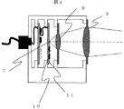
図4は、図1に示した速度センサ構成におけるセンサ部分の断面図である。図4において、ドップラーセンサを構成するために必要な回路ブロックはMMIC10で構成されており、さらにこれらのMMIC10は高周波基板11上に実装されている。電磁波を送信するための送信アンテナおよび反射信号を受信するための受信アンテナは、高周波基板11上に平面アンテナ7として形成されている。このアンテナ7から放射された電磁波は、第一の誘電体レンズ8により、放射角が狭められ、第2の誘電体レンズ9により、地面付近でのビーム幅(例えばビーム断面の最大径と定義してもよい)がセンサの電磁波放射口付近でのビーム幅より小さいかまたはほぼ同じとなるようにビーム形状に形成される。
FIG. 4 is a cross-sectional view of a sensor portion in the speed sensor configuration shown in FIG. In FIG. 4, a circuit block necessary for constituting the Doppler sensor is constituted by an
図5は、本実施例で使用されるドップラーセンサのブロック図の一例を示す。ドップラーセンサは、信号を生成するための発振器12、送信信号を放射するための送信アンテナ14、反射信号を受信するための受信アンテナ15、および受信した反射信号と局部信号とを混合して相対速度の算出に必要な低周波信号を生成する混合器13を具備してなる。ここで、速度センサの使用条件等により十分な感度が得られない場合などに適用するために、適宜、送信信号を増幅するための電力増幅器16や受信した反射信号を増幅するための低雑音増幅器17を具備する構成とし、以て、送受信される電磁波に対するドップラーセンサの感度を補償するようにしてもよい。
FIG. 5 shows an example of a block diagram of a Doppler sensor used in this embodiment. The Doppler sensor includes an oscillator 12 for generating a signal, a transmission antenna 14 for radiating a transmission signal, a
次に、図5に示した回路構成の動作を以下に説明する。まず、発振器12により所望の周波数信号を生成する。周波数信号としては、よく知られたマイクロ波やミリ波などの高周波信号とするのが好適である。この信号は、分配器36により分配され、一方は、直接または電力増幅器16にて増幅された後、送信アンテナ14へ送られ、送信アンテナ14から対象物、すなわち地面に向けて放射される。地面により反射された反射信号は、受信アンテナ15により受信され、直接または低雑音増幅器17により増幅された後、混合器13に入力される。混合器13では、元の送信信号と同じ信号を局部信号として受信した反射信号と混合することで、ドップラー効果による送信信号と反射信号との間の周波数シフト量を周波数とする低周波信号を生成する。この低周波信号に信号処理を行い、その周波数成分を検出することで、[数1]より速度の計算が行われる。
Next, the operation of the circuit configuration shown in FIG. 5 will be described below. First, a desired frequency signal is generated by the oscillator 12. The frequency signal is preferably a high-frequency signal such as a well-known microwave or millimeter wave. This signal is distributed by the distributor 36, and one is amplified directly or by the power amplifier 16, then sent to the transmission antenna 14, and radiated from the transmission antenna 14 toward the object, that is, the ground. The reflected signal reflected by the ground is received by the receiving
図6は、本実施例における信号処理の流れと、それを構成する各機能ブロックとを示している。速度センサ1から出力されたアナログ信号は、A/Dコンバータ18によりディジタル信号に変換されて、信号処理装置22に入力される。信号処理装置22では、まず、FFT19においてFFT(Fast Fourier Transform:高速フーリエ変換)などの信号処理を行い時間領域の信号から周波数領域の信号に変換した後、Peak20において信号スペクトルの中から地面からの反射信号に相当する信号スペクトルを検出する。さらに、Calc21において[数1]の換算式を用いて信号スペクトルの周波数から速度に換算する。
FIG. 6 shows the flow of signal processing in this embodiment and the functional blocks constituting it. The analog signal output from the
なお、信号処理装置22は、車体5の任意の位置に設置されるのが好適であるが、本発明はこれに限定されず、例えば、車両の走行範囲が狭い範囲に限定されるような条件下においては、無線通信装置を介して車体5の外部に設置されるようにしてもよい。信号処理装置22を車体5に設置した場合、車体外部の環境(例えば、無線通信装置を介して車体5の外部で信号処理を行う場合は通信環境)によらず安定した処理が可能であるという効果がある。一方、信号処理装置22を車体5の外部に設置した場合、センサ部分をより簡易に構成することが可能であり、個々の車両に取り付けるセンサを低コストで製造することが可能であるという効果がある。
The signal processing device 22 is preferably installed at an arbitrary position of the
また、本実施例においては、A/Dコンバータ18が速度センサ1の外部に設けられる構成を説明したが、本発明はこれに限定されず、例えば、速度センサ1の筐体内部に設けられるようにしてもよい。A/Dコンバータ18を速度センサ1の外部に設置した場合、筐体内部には、高周波回路部分を含めてアナログ回路しか存在しないため、A/Dコンバータによる雑音、特に電源線を介してセンサのアナログ回路部分に流入する雑音を低減することができるという効果がある。一方、A/Dコンバータ18を速度センサ1の筐体内部に設けた場合、筐体外部に出力される信号はディジタル信号となるため、筐体外部に存在する雑音に対して、より安定した信号を得ることが可能であるという効果がある。
In the present embodiment, the configuration in which the A / D converter 18 is provided outside the
図20は、図15に示した車両5とは車高hが異なる車両の概観図を示す。図20のように、取り付ける車種が、例えば大型トラックなどのように車高h2がhよりも高い車種である場合、図15に示したθと同じ角度で速度センサ1を取り付けると、速度センサ1と地面6との間の距離d2が大きくなり、速度センサ1の感度が不足することが予想される。この場合、速度センサ1の電磁波の放射角度θ2がθよりも大きくなるように速度センサ1を設置することで、速度センサ1と地面6との間の距離d2を図15のdと同程度に保つことができ、以て、速度センサ1の感度不足を補償することが可能である。また、逆に車高h2がhよりも低い車種に取り付けた場合は、図15に示したθと同じ角度で速度センサ1を取り付けると、速度センサ1と地面6との間の距離d2が小さくなり、速度センサ1の感度が過剰となる。そこで、速度センサ1と地面6との間の距離d2が図15のdと同程度となるまで速度センサ1の電磁波の放射角度θ2を小さくして、速度センサ1の感度を最適に保つことができる。この場合、放射角度θ2が小さくなった分、速度センサ1の速度分解能が向上するという効果も得られる。
FIG. 20 shows an overview of a vehicle having a vehicle height h different from that of the
以上、本実施例によれば、地面に照射している電磁波の面積を小さく抑えることが可能であるため、検知誤差を低減することが可能であるという効果がある。
なお、以上の実施例では、誘電体レンズが2枚の場合を用いて説明したが、誘電体レンズが3枚以上の複数枚であっても同様の効果が得られることは言うまでもない。また、同等のビーム形状を得るために、誘電体レンズ以外に、大口径アンテナ、アンテナアレー、パラボラアンテナ、または、これらの組合せを用いてもよいことは、上述した通りである。
As described above, according to this embodiment, it is possible to reduce the area of the electromagnetic wave applied to the ground, and thus there is an effect that detection errors can be reduced.
In the above embodiment, the case where there are two dielectric lenses has been described, but it goes without saying that the same effect can be obtained even if there are a plurality of dielectric lenses. Further, as described above, in order to obtain an equivalent beam shape, a large aperture antenna, an antenna array, a parabolic antenna, or a combination thereof may be used in addition to the dielectric lens.
さらに、本発明の速度センサは、送信信号(送信電磁波)を送信する送信器と反射信号(反射電磁波)を受信する受信器とが単一のセンサ部分筐体内の互いに近接した位置に設置されるため、反射波のサイドローブを反射信号として受信するために受信器を送信器から離して設置する構成とは異なり、車高hが変化しても、電磁波の放射角度θを適切に設定することで、速度センサ1の装置サイズを変更することなく、速度センサ1に固有の検知感度に見合った最適な検知距離dを確保することが可能となり、場合によっては、速度分解能の向上も可能となる。これは見方を変えると、電磁波の放射角度θを適切に設定することで、特に速度センサ1が固有に持つ検知感度(検知性能)を変更することなく、所定の範囲内で異なる車高hを有するさまざまな車種に速度センサ1が適用可能となるということでもある。すなわち、本実施例によれば、適用車種ごとに速度センサ1を別々に設計・製造する必要がなくなり、以て、流通性が向上するばかりでなく、設計コストの低減も期待できるという効果がある。
Furthermore, in the speed sensor of the present invention, a transmitter for transmitting a transmission signal (transmitted electromagnetic wave) and a receiver for receiving a reflected signal (reflected electromagnetic wave) are installed in positions close to each other in a single sensor partial housing. Therefore, unlike the configuration in which the receiver is placed away from the transmitter in order to receive the side lobe of the reflected wave as a reflected signal, the electromagnetic wave radiation angle θ should be set appropriately even if the vehicle height h changes. Therefore, it is possible to secure an optimum detection distance d corresponding to the detection sensitivity inherent to the
図14は、本発明の別の実施例である第2の実施例の速度センサ構成におけるセンサ部分の断面図を示している。図14において、ドップラーセンサを構成するために必要な回路ブロックはMMIC10で構成されており、さらにこれらのMMIC10は高周波基板11上に実装されている。電磁波を送信するための送信アンテナと反射信号を受信するための受信アンテナは、高周波基板11上に平面アンテナ7として形成されている。これらの高周波回路は高周波用のパッケージ38により封止される。高周波用のパッケージ38としては、例えば金属製のパッケージが用いられる。以下に、金属パッケージを用いた場合を例に説明する。パッケージ38には、アンテナから放射された電磁波を通過させるための窓が設けられており、その窓の部分に第一の誘電体レンズ8が設けられている。この第一の誘電体レンズ8と第二の誘電体レンズ9により、地面付近での電磁波の照射面積がセンサの電磁波放射口の面積より小さくなるようにビーム形状に形成される。
FIG. 14 shows a cross-sectional view of a sensor portion in the speed sensor configuration of the second embodiment which is another embodiment of the present invention. In FIG. 14, a circuit block necessary for configuring the Doppler sensor is configured by an
本実施例によれば、高周波回路部分を個別に実装しパッケージ内に封止できるため、高周波回路の実装技術を必要とする比較的コストの高い組立工程と、そうでない組立工程とを分離することができ、以て、速度センサの製造プロセスの自由度を向上させることができる、あるいは、速度センサ構成の中でドップラーセンサ回路として機能する部分の実装コストを低減できるという効果がある。 According to the present embodiment, since the high-frequency circuit portion can be individually mounted and sealed in the package, a relatively expensive assembly process that requires high-frequency circuit mounting technology and an assembly process that does not need to be separated. Therefore, there is an effect that the degree of freedom of the manufacturing process of the speed sensor can be improved, or the mounting cost of the part functioning as a Doppler sensor circuit in the speed sensor configuration can be reduced.
図7は、本発明のさらに別の実施例である第3の実施例の速度センサ構成におけるセンサ部分の断面図を示している。ドップラーセンサに必要な能動回路およびアンテナは、ICパッケージ23に封入されている。さらに、このICパッケージ23は、電磁波を放射する側に第一の誘電体レンズ8を具備して構成される。
FIG. 7 shows a sectional view of a sensor portion in the speed sensor configuration of the third embodiment which is still another embodiment of the present invention. An active circuit and an antenna necessary for the Doppler sensor are enclosed in an
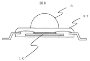
図8はICパッケージ23の断面図であり、図16は平面概観図である。また、図17は、このICパッケージ23内部のMMIC部分を通るようにICパッケージ23の装着面に平行な面でICパッケージ23を切断したときの切断面の概観図を示す。発振器、ミキサ、混合器、電力増幅器、低雑音増幅器、送信アンテナ、および、受信アンテナは、それぞれ個別のMMICや高周波基板を用いて構成することが可能であるが、これら全てを1チップのMMIC上にモノリシックに形成すると低コスト化に適している。本実施例では、1チップのMMIC10として形成されている例で説明する。このように全ての高周波回路をモノリシックに集積することで、アンテナにて放射または受信される電磁波以外に、このMMIC10の外部へ高周波信号を伝送する必要がなくなるため、安価な実装方法が利用可能になる。本実施例ではMMIC10は樹脂モールドパッケージ37により実装されている。
8 is a cross-sectional view of the
さらに、樹脂モールドパッケージ37の図中上部には第1の誘電体レンズ8が形成されている。この誘電体レンズ8は、樹脂モールドパッケージ37と同一の材料で形成されるのが好適であり、その場合、大量生産時に金型による一体形成が可能となる。MMIC10上には、送信アンテナおよび受信アンテナが、例えばマイクロストリップパッチアンテナ等の平面アンテナとして形成されている。このとき、MMICの製造コストは、その面積に依存するため、MMIC10上に形成するアンテナ26としては、アレー化されていない、素子数の少ない、例えば、一つの素子からなるパッチアンテナで構成されるのが好適である。特にこのような素子数の少ないアンテナを用いた場合、通常、アンテナから放射される電磁波の放射角が広くなる。第一の誘電体レンズ8は、このアンテナから放射される電磁波の放射角を狭め、その放射された電磁波のほとんど全てを第二の誘電体レンズに入射させて損失を低減させる効果を持っている。さらに、第二の誘電体レンズを用いて、電磁波の集光を行う。ここで、対象物付近すなわち地面付近での電磁波ビーム幅(例えばビーム断面の最大径と定義してもよい)がセンサの電磁波放射口付近での電磁波ビーム幅すなわち第二の誘電体レンズの最大径より小さいかまたはほぼ同じとなるように電磁波を集光するよう、第二の誘電体レンズを構成することにより、上述の原理から検知誤差を低減することが可能となる。
Further, a first
図9は、このMMIC10の回路図の一例である。この回路では、発振器を自己混合型の発振器とすることで、ドップラーセンサに必要な発振器および混合器の役割を一つのFET(Field Effect Transistor:電界効果トランジスタ)27で実現している。FET27はラジアルスタブ29により負帰還がかけられ負性抵抗を発生し、オープンスタブ型の共振器28により、発振すべき周波数で共振させることで希望の周波数での発振動作を実現する。MMIC10上のアンテナ26は、送信アンテナと受信アンテナとを兼ねており、FET27により生成された信号を放射すると同時に、対象物からの反射信号を受信する。受信した反射信号はFET27により混合され、ドップラー効果により生じた送信信号と反射信号との間の周波数シフト量を周波数とする低周波信号が生成される。
FIG. 9 is an example of a circuit diagram of the
ところで、本実施例のような構成の場合、MMIC10上のアンテナ26と第一の誘電体レンズ8との距離は1mm程度、またはそれ以下であり、非常に短い。したがって、第二の誘電体レンズ9を用いないで、第一の誘電体レンズ8のみで集光を行う場合、[数3]で示したように、第一の誘電体レンズ8は非常に高い精度で精密に加工する必要がある。
By the way, in the case of the configuration as in this embodiment, the distance between the
図18は、その一例として、レンズと集光点までの距離bを500mmとして設計した場合において、レンズの製造誤差により焦点fに誤差が生じたときに発生する、レンズと集光点までの距離の誤差Δbを示す。同図においては、アンテナとレンズとの間の距離aを横軸として、製造によるレンズの焦点の誤差Δfが−0.1mmの場合と−0.2mmの場合とをプロットしている。同図に示すように、本実施例のようなMMIC10上のアンテナ26と第一の誘電体レンズ8との間の距離が1mm程度と小さい場合、集光点の誤差Δbは非常に大きくなる。
FIG. 18 shows, as an example, the distance between the lens and the condensing point that occurs when an error occurs in the focal point f due to a manufacturing error of the lens when the distance b between the lens and the condensing point is designed to be 500 mm. The error Δb is shown. In the figure, the distance a between the antenna and the lens is plotted on the horizontal axis, and the case where the lens focus error Δf due to manufacture is −0.1 mm and −0.2 mm are plotted. As shown in the figure, when the distance between the
この問題を解決するために、誘電体レンズとアンテナとの間の距離aを大きくする必要があるが、この場合、前述のようにMMIC10上に設けられたアンテナ26から放射される電磁波の放射角が非常に大きくなるため、これをカバーする誘電体レンズの径は非常に大きいものとなる。そこで、本実施例では、第一の誘電体レンズ8の他にさらに第二の誘電体レンズ9を用いる。このとき、第一の誘電体レンズ8は、電磁波の放射角は小さくするが、電磁波の結像点は依然として無限遠点にあるように設定し、第二の誘電体レンズ9により所望の距離に集光点が作られる構造とする。
In order to solve this problem, it is necessary to increase the distance a between the dielectric lens and the antenna. In this case, the radiation angle of the electromagnetic wave radiated from the
本実施例によれば、ドップラーセンサ部分と第一の誘電体レンズとを安価な製造コストで構成できるという効果がある。 According to this embodiment, there is an effect that the Doppler sensor portion and the first dielectric lens can be configured at a low manufacturing cost.
図10は、本発明のさらに別の実施例である第4の実施例の速度センサ構成におけるセンサ部分の断面図を示している。本実施例は、複数個、特に3個の誘電体レンズを組み合わせて速度センサのセンサ部分が構成されている例である。本実施例では、第一の誘電体レンズ8と第二の誘電体レンズ9との間に、第三の誘電体レンズ30が設けられている。ドップラーセンサ回路部分が樹脂モールドパッケージに実装され、さらに第一の誘電体レンズが樹脂モールドパッケージ上に直接配置されて、ICパッケージ23を構成している点は、上記第3の実施例と同様である。しかしながら、ドップラーセンサ回路部分の具体的構成や第一の誘電体レンズの位置などは、これに限定されない。本実施例では、MMIC10上に配置されたアンテナ26から放射された放射角の広い電磁波は、第一の誘電体レンズ8により放射角が狭められている。さらに、第二の誘電体レンズ9と第三の誘電体レンズ30との組合せによりビームの形成を行っている。
FIG. 10 shows a sectional view of a sensor portion in the speed sensor configuration of the fourth embodiment which is still another embodiment of the present invention. This embodiment is an example in which a sensor portion of a speed sensor is configured by combining a plurality of, in particular, three dielectric lenses. In the present embodiment, a third
本実施例によれば、誘電体レンズを複数個用いることで、ビームの形成に対する自由度が大きくなるという効果がある。なお、誘電体レンズが4個以上設けられている場合、その自由度がさらに大きくなるという効果があることは言うまでもない。 According to the present embodiment, by using a plurality of dielectric lenses, there is an effect that the degree of freedom for forming the beam is increased. Needless to say, when four or more dielectric lenses are provided, the degree of freedom is further increased.
図11は、本発明のさらに別の実施例である第5の実施例の速度センサ構成におけるセンサ部分の断面図を示している。また、図12は、図11を正面から見た図すなわち同図中右側から電磁波放射方向と正反対の方向にセンサ部分を見た図である。なお、この図11では分かりやすくするために、第2の誘電体レンズ9は図示していない。本実施例においては、ドップラーセンサ31から放射される電磁波は、パラボラ形状(回転放物面形状)を有する側壁32により反射される。反射された電磁波は、さらに、第2の誘電体レンズ9により集光される。なお、パラボラ形状のアンテナを使用する場合、パラボラ形状の側壁側に向けて電磁波を照射する必要があるため、ドップラーセンサは十分に細い支柱33により可動的または固定的に支持されたマウント台34上に実装されるのが好適である。
FIG. 11 shows a sectional view of a sensor portion in the speed sensor configuration of the fifth embodiment which is still another embodiment of the present invention. FIG. 12 is a view of FIG. 11 as viewed from the front, that is, a view of the sensor portion viewed from the right side in the same direction as the electromagnetic wave radiation direction. In FIG. 11, the second
本実施例によれば、センサ部分筐体内にパラボラアンテナが作り込まれた構成としたことで第一の誘電体レンズの機能をセンサ部分の筐体そのものに持たせることができるため、別体部品としての第一の誘電体レンズが不要となり、以て、部品点数削減による製造コスト低減などの効果が期待される。 According to the present embodiment, since the parabolic antenna is built in the sensor part casing, the function of the first dielectric lens can be given to the sensor part casing itself. As a result, the first dielectric lens is not required, so that an effect such as a reduction in manufacturing cost due to a reduction in the number of parts is expected.
図13は、本発明のさらに別の実施例である第6の実施例の速度センサ構成におけるセンサ部分の断面図を示している。本実施例の特徴は、センサ部分が第二の誘電体レンズ9の位置を調整する調整機構35を具備している点である。対地車速センサを車両に取り付ける場合、車両の種類によってセンサから地面までの高さhが異なる場合がある。その場合、誘電体レンズによるビーム形状の形成を車種に応じて最適にするために、調整機構35により第2の誘電体レンズ9の位置を調整すれば好適である。
FIG. 13 shows a cross-sectional view of the sensor portion in the speed sensor configuration of the sixth embodiment which is still another embodiment of the present invention. The feature of this embodiment is that the sensor portion includes an
なお、車種によって車高は、ほぼ一義的に決まるので、第二の誘電体レンズ9の位置は、速度センサが取り付けられる車両の車種に基づいて決定することができる。しかし、例えばその車両が使用するタイヤの空気圧や摩耗の度合、あるいはその他の条件によって、たとえ車種が同一であっても、初期状態から経時的に変化して、あるいは同一車種の個々の車両間で、車高が異なっている場合があると考えられる。また、道路環境によっても、サスペンションの変動により車高は変動する。このようなさまざまな状況に対応可能ならしめるために、図19のように、車高を判定するための距離センサ39を、例えば別体の外付け部品として設け、そのセンサの検知出力に基づいて、制御装置40により調整機構35を調整することで、第二の誘電体レンズ9の位置を自動的に調整することも可能である。この距離センサ39としては、電磁波や超音波を用いる距離センサが利用可能であるが、本発明はこれに限定されず、対象物との距離を検知し、それに基づく物理量を電気的に出力可能な部品あるいは装置であれば種々適用可能である。
In addition, since the vehicle height is determined almost uniquely depending on the vehicle type, the position of the second
さらには、レーダの技術をこの対地車速センサに適用することで、対地車速センサ自体に車高を検知するための距離センサ39の機能を持たせることが可能である。この場合、対地車速センサの出力から、対地速度と地面までの距離とを算出することが可能であるため、外部の距離センサ39は不要となる。
Furthermore, by applying the radar technology to the ground vehicle speed sensor, the ground vehicle speed sensor itself can have the function of the
本実施例によれば、車高によって地面に照射される電磁波の面積が変化することを補正することが可能であるため、車種によらない高精度な速度検知が可能である。
なお、以上においては、誘電体レンズを2個使用する例として本実施例を説明したが、誘電体レンズを3個以上使用する場合や、パラボラアンテナやアレーアンテナと誘電体レンズとを組み合わせて使用する場合でも、少なくとも同等の効果が得られることは言うまでもない。
According to the present embodiment, it is possible to correct the change in the area of the electromagnetic wave irradiated to the ground due to the vehicle height, and therefore it is possible to detect the speed with high accuracy regardless of the vehicle type.
In the above, the present embodiment has been described as an example in which two dielectric lenses are used. However, when three or more dielectric lenses are used, a parabolic antenna, an array antenna, and a dielectric lens are used in combination. Of course, at least the same effect can be obtained.
なお、以上の実施例1〜6の説明においては、マイクロ波やミリ波などの電磁波を利用する速度センサを例に挙げて説明したが、本発明はこれに限定されず、光や超音波などを利用する速度センサに適用しても、少なくとも同等の効果が得られることは言うまでもない。 In the above description of the first to sixth embodiments, a speed sensor using an electromagnetic wave such as a microwave or a millimeter wave has been described as an example. However, the present invention is not limited to this, and light, ultrasonic waves, and the like are used. Needless to say, at least the same effect can be obtained even if applied to a speed sensor using the
また、地面に対する速度を測定する対地車速センサを例に挙げて説明したが、本発明はこれに限定されず、他の対象物を測定する種々の速度センサに適用しても、少なくとも同等の効果が得られることは言うまでもない。 In addition, the ground vehicle speed sensor that measures the speed with respect to the ground has been described as an example, but the present invention is not limited to this, and even when applied to various speed sensors that measure other objects, at least the same effect It goes without saying that can be obtained.
また、本発明の速度センサおよびそれを用いた対地車速センサが放射する電磁波のビーム形状は、上記実施例1〜6として開示したものに限定されず、センサ近傍でのビーム幅に対して地面近傍でのビーム幅が小さくなるビーム形状であれば種々の形状のものを適用可能であり、そのいずれのビーム形状を形成する場合にも、上記の各実施例に開示した装置構成は有効である。
また、上述した各実施例の構成を適宜組み合わせることにより、少なくとも各実施例から得られる効果が総合された効果が得られることは言うまでもない。
Further, the beam shape of the electromagnetic wave radiated by the speed sensor of the present invention and the ground vehicle speed sensor using the speed sensor is not limited to that disclosed as the first to sixth embodiments, but is near the ground with respect to the beam width in the vicinity of the sensor. Various beam shapes can be applied as long as the beam width is small, and the apparatus configurations disclosed in the above embodiments are effective in forming any beam shape.
Needless to say, by combining the configurations of the above-described embodiments as appropriate, at least the effects obtained from the embodiments can be combined.
1 速度センサ
2 誘電体レンズ
3 センサ回路部
4 ビーム
5 車体
6 地面
7 アンテナ
8 第一の誘電体レンズ
9 第二の誘電体レンズ
10 MMIC
11 高周波基板
12 発振器
13 混合器
14 送信アンテナ
15 受信アンテナ
16 電力増幅器
17 低雑音増幅器
18 A/Dコンバータ
19 信号処理におけるFFTのステップ
20 信号処理における信号検出ステップ
21 信号処理における速度計算のステップ
22 信号処理装置
23 ICパッケージ
26 送受信アンテナ
27 FET
28 オープンスタブ
29 ラジアルスタブ
30 第三の誘電体レンズ
31 ドップラーセンサ
32 側壁
33 支柱
34 マウント台
35 調整機構
36 分配器
37 樹脂モールドパッケージ
38 金属筐体
39 距離センサ
40 制御装置。
DESCRIPTION OF
DESCRIPTION OF SYMBOLS 11 High frequency board | substrate 12 Oscillator 13 Mixer 14
28
Claims (4)
波動の性質を有する送信信号を生成し、該送信信号が対象物により反射することによって生じる反射信号を受信し、受信した前記反射信号と前記送信信号とから、前記移動可能な物体と前記対象物との間の相対速度を算出するのに必要な信号を生成して出力するセンサ回路部と、
該センサ回路部により生成された送信信号の放射角度を変更するためのレンズと
を具備して成り、
前記センサ回路部は、基板と、該基板に搭載された集積回路装置と、該集積回路装置と電気的に接続され、前記送信信号を放射する送信アンテナと、前記集積回路装置と電気的に接続され、前記反射信号を受信するための受信アンテナとを具備して成り、
前記送信信号は電磁波であり、前記レンズは前記電磁波の焦点距離を変更可能に構成された誘電体レンズであり、
前記誘電体レンズは、第1の誘電体レンズと、該第1の誘電体レンズとは別体として設けられた第2の誘電体レンズとを含んで構成され、
前記第1および第2の誘電体レンズのうち少なくとも一方の前記速度センサ内における位置を調整する調整機構を更に具備して成り、
前記送信信号はビーム形状を成し、該ビーム形状は、前記対象物近傍でのビーム幅が前記速度センサの前記送信信号を放射するための放射口近傍でのビーム幅と比べてほぼ等しいかまたは小さくなるように前記レンズによって形成され、
前記送信信号は、前記移動可能な物体の前記対象物に対する相対速度方向と所定の角度を成す方向に前記放射口から放射され、前記所定の角度は、0度より大きく90度より小さいかまたは90度より大きく180度より小さいかのいずれかの任意の角度であり、
前記送信アンテナおよび前記受信アンテナのうちの少なくとも一方は、前記センサ回路部を構成する能動回路と共に同一の半導体基板上にモノリシックに形成され、
前記半導体基板は樹脂モールドパッケージにより実装され、
前記第1の誘電体レンズは、前記樹脂モールドパッケージ上に一体形成されている
ことを特徴とする速度センサ。 A speed sensor configured to be installed on a movable object,
A transmission signal having a wave property is generated, a reflection signal generated by reflection of the transmission signal by an object is received, and the movable object and the object are received from the received reflection signal and the transmission signal. A sensor circuit unit that generates and outputs a signal necessary to calculate the relative speed between
A lens for changing the radiation angle of the transmission signal generated by the sensor circuit unit,
The sensor circuit unit includes a substrate, an integrated circuit device mounted on the substrate, a transmission antenna that is electrically connected to the integrated circuit device and radiates the transmission signal, and is electrically connected to the integrated circuit device. A receiving antenna for receiving the reflected signal,
The transmission signal is an electromagnetic wave, and the lens is a dielectric lens configured to be able to change the focal length of the electromagnetic wave,
The dielectric lens includes a first dielectric lens and a second dielectric lens provided separately from the first dielectric lens,
Ri further comprising forming an adjustment mechanism for adjusting the position of at least one of the velocity in the sensor of the first and second dielectric lens,
The transmission signal has a beam shape, and the beam shape is substantially equal to a beam width in the vicinity of the object compared to a beam width in the vicinity of a radiation port for emitting the transmission signal of the velocity sensor, or Formed by the lens to be small,
The transmission signal is emitted from the radiation port in a direction that forms a predetermined angle with a relative velocity direction of the movable object with respect to the target, and the predetermined angle is greater than 0 degree and smaller than 90 degrees or 90 degrees. Any angle greater than 180 degrees and less than 180 degrees,
At least one of the transmitting antenna and the receiving antenna is formed monolithically on the same semiconductor substrate together with an active circuit constituting the sensor circuit unit,
The semiconductor substrate is mounted by a resin mold package,
The speed sensor, wherein the first dielectric lens is integrally formed on the resin mold package .
前記電磁波はマイクロ波帯からミリ波帯域の電磁波である
ことを特徴とする速度センサ。 In claim 1,
The speed sensor characterized in that the electromagnetic wave is an electromagnetic wave in a microwave band to a millimeter wave band .
前記送信アンテナおよび前記受信アンテナのうちの少なくとも一方は、パラボラ形状の側壁を具備して成る
ことを特徴とする速度センサ。 In either claim 1 or 2,
The speed sensor, wherein at least one of the transmission antenna and the reception antenna includes a parabolic side wall .
前記対象物と前記速度センサとの間の距離に関する情報を含んだ信号に基づいて前記調整機構を制御する制御装置を更に具備して成る
ことを特徴とする速度センサ。 In any one of claims 1 to 3,
The speed sensor, further comprising a control device that controls the adjustment mechanism based on a signal including information on a distance between the object and the speed sensor.
Priority Applications (4)
| Application Number | Priority Date | Filing Date | Title |
|---|---|---|---|
| JP2004378770A JP4456998B2 (en) | 2004-12-28 | 2004-12-28 | Speed sensor and ground vehicle speed sensor using the same |
| EP05017796A EP1677126A1 (en) | 2004-12-28 | 2005-08-16 | Doppler-velocity-sensor for a vehicle with focused beam |
| US11/207,004 US7310061B2 (en) | 2004-12-28 | 2005-08-19 | Velocity sensor and ground vehicle velocity sensor using the same |
| US11/984,571 US7532153B2 (en) | 2004-12-28 | 2007-11-20 | Velocity sensor and ground vehicle velocity sensor using the same |
Applications Claiming Priority (1)
| Application Number | Priority Date | Filing Date | Title |
|---|---|---|---|
| JP2004378770A JP4456998B2 (en) | 2004-12-28 | 2004-12-28 | Speed sensor and ground vehicle speed sensor using the same |
Publications (3)
| Publication Number | Publication Date |
|---|---|
| JP2006184144A JP2006184144A (en) | 2006-07-13 |
| JP2006184144A5 JP2006184144A5 (en) | 2007-07-19 |
| JP4456998B2 true JP4456998B2 (en) | 2010-04-28 |
Family
ID=36177824
Family Applications (1)
| Application Number | Title | Priority Date | Filing Date |
|---|---|---|---|
| JP2004378770A Active JP4456998B2 (en) | 2004-12-28 | 2004-12-28 | Speed sensor and ground vehicle speed sensor using the same |
Country Status (3)
| Country | Link |
|---|---|
| US (2) | US7310061B2 (en) |
| EP (1) | EP1677126A1 (en) |
| JP (1) | JP4456998B2 (en) |
Families Citing this family (42)
| Publication number | Priority date | Publication date | Assignee | Title |
|---|---|---|---|---|
| WO2006018956A1 (en) * | 2004-08-19 | 2006-02-23 | Electronic Navigation Research Institute, An Independent Administrative Institution | Device using dielectric lens |
| JP4456998B2 (en) * | 2004-12-28 | 2010-04-28 | 日立オートモティブシステムズ株式会社 | Speed sensor and ground vehicle speed sensor using the same |
| JP4286855B2 (en) * | 2006-09-07 | 2009-07-01 | 株式会社日立製作所 | Radar equipment |
| JP4294670B2 (en) * | 2006-09-15 | 2009-07-15 | シャープ株式会社 | Wireless communication device |
| US20080180336A1 (en) * | 2007-01-31 | 2008-07-31 | Bauregger Frank N | Lensed antenna methods and systems for navigation or other signals |
| CN101680945B (en) | 2007-04-02 | 2013-07-24 | 独立行政法人情报通信研究机构 | Microwave/millimeter wave sensor apparatus |
| DE102007034329A1 (en) * | 2007-07-24 | 2009-01-29 | Robert Bosch Gmbh | radar device |
| DE102007036262A1 (en) * | 2007-08-02 | 2009-02-05 | Robert Bosch Gmbh | Radar sensor for motor vehicles |
| US8115673B1 (en) * | 2007-08-11 | 2012-02-14 | Mcewan Technologies, Llc | Self-oscillating UWB emitter-detector |
| US8022861B2 (en) * | 2008-04-04 | 2011-09-20 | Toyota Motor Engineering & Manufacturing North America, Inc. | Dual-band antenna array and RF front-end for mm-wave imager and radar |
| US8380140B2 (en) * | 2008-09-26 | 2013-02-19 | National Institute Of Information And Communications Technology | Microwave/millimeter wave communication apparatus |
| JP5761585B2 (en) * | 2008-10-07 | 2015-08-12 | 国立研究開発法人情報通信研究機構 | Pulse radar equipment |
| JP5565823B2 (en) * | 2008-10-07 | 2014-08-06 | 独立行政法人情報通信研究機構 | Pulse signal generator |
| US8378759B2 (en) * | 2009-01-16 | 2013-02-19 | Toyota Motor Engineering & Manufacturing North America, Inc. | First and second coplanar microstrip lines separated by rows of vias for reducing cross-talk there between |
| US8786496B2 (en) | 2010-07-28 | 2014-07-22 | Toyota Motor Engineering & Manufacturing North America, Inc. | Three-dimensional array antenna on a substrate with enhanced backlobe suppression for mm-wave automotive applications |
| US20120154239A1 (en) * | 2010-12-15 | 2012-06-21 | Bridgewave Communications, Inc. | Millimeter wave radio assembly with a compact antenna |
| US8441394B2 (en) * | 2011-07-11 | 2013-05-14 | Delphi Technologies, Inc. | System and method for detecting obstructions and misalignment of ground vehicle radar systems |
| EP2839541A1 (en) * | 2012-04-17 | 2015-02-25 | Keyssa, Inc. | Dielectric lens structures for interchip communication |
| JP6121680B2 (en) | 2012-10-05 | 2017-04-26 | 日立オートモティブシステムズ株式会社 | Radar module and speed measurement device using the same |
| US8854257B2 (en) * | 2012-10-22 | 2014-10-07 | The United States Of America As Represented By The Secretary Of The Army | Conformal array, luneburg lens antenna system |
| JP2014155098A (en) * | 2013-02-12 | 2014-08-25 | Nitto Denko Corp | Antenna module and method for manufacturing the same |
| JP5941854B2 (en) | 2013-02-13 | 2016-06-29 | 日立オートモティブシステムズ株式会社 | Millimeter-wave dielectric lens antenna and speed sensor using the same |
| DE102013105789B3 (en) * | 2013-06-05 | 2014-11-13 | Fraunhofer-Gesellschaft zur Förderung der angewandten Forschung e.V. | Collimator for electromagnetic high-frequency radiation |
| JP6371510B2 (en) * | 2013-09-30 | 2018-08-08 | 日野自動車株式会社 | On-vehicle radar axis adjustment device and axis adjustment method |
| DE102016120665B3 (en) | 2016-10-28 | 2018-04-05 | Silicon Radar GmbH | Radar sensor unit for use in harsh environments |
| US10756441B2 (en) * | 2017-02-21 | 2020-08-25 | Taoglas Group Holdings Limited | Radar lens antenna arrays and methods |
| WO2019079323A1 (en) * | 2017-10-17 | 2019-04-25 | California Institute Of Technology | Sub-surface imaging of dielectric structures and voids via narrowband electromagnetic resonance scattering |
| EP3490060B1 (en) | 2017-11-27 | 2022-07-27 | Panasonic Intellectual Property Management Co., Ltd. | Radar device |
| CN109839629B (en) | 2017-11-27 | 2023-06-27 | 松下知识产权经营株式会社 | Radar apparatus |
| CN109073743A (en) * | 2017-12-18 | 2018-12-21 | 深圳市大疆创新科技有限公司 | Weak target detection method, microwave radar sensor and unmanned plane |
| US10921447B2 (en) * | 2018-01-29 | 2021-02-16 | Rohm Co., Ltd. | Control circuit of light emitting and receiving device |
| FR3090893B1 (en) * | 2018-12-20 | 2021-10-08 | Commissariat Energie Atomique | METHOD AND SYSTEM FOR MEASURING THE SPEED OF A CARRIER IN RELATION TO THE GROUND |
| HUE054958T2 (en) * | 2019-02-04 | 2021-10-28 | Grieshaber Vega Kg | Antenna assembly |
| DE102019202144A1 (en) * | 2019-02-18 | 2020-08-20 | Vega Grieshaber Kg | Radar sensor for factory and logistics automation |
| KR102588510B1 (en) * | 2019-04-22 | 2023-10-12 | 현대자동차주식회사 | Antenna system for vehicle and mtehod of controlling the same |
| CN111862631B (en) * | 2019-05-24 | 2022-07-29 | 北京骑胜科技有限公司 | Vehicle running detection method and device, electronic equipment and readable storage medium |
| JP2019213222A (en) * | 2019-09-05 | 2019-12-12 | パナソニックIpマネジメント株式会社 | vehicle |
| CN112924711B (en) * | 2021-01-22 | 2023-08-11 | 香港中文大学(深圳) | Vehicle speed detection method and device and computer readable storage medium |
| US11990685B2 (en) * | 2021-05-27 | 2024-05-21 | Tata Consultancy Services Limited | Computer controlled electromechanical MMW frequency antenna scanning system and beam steering thereof |
| JP2023075586A (en) * | 2021-11-19 | 2023-05-31 | 本田技研工業株式会社 | Ground speed measurement device and saddle-riding type vehicle |
| EP4243205A1 (en) * | 2022-03-09 | 2023-09-13 | Vaisala, OYJ | An antenna for a radar apparatus |
| WO2024114885A1 (en) | 2022-11-28 | 2024-06-06 | Volvo Truck Corporation | A wheel axle mounted vehicle ground radar system |
Family Cites Families (21)
| Publication number | Priority date | Publication date | Assignee | Title |
|---|---|---|---|---|
| FR595085A (en) * | 1924-01-19 | 1925-09-25 | Method and devices for measuring and controlling the speed of a ship by directed beams of ultrasonic waves | |
| US2834014A (en) * | 1950-02-16 | 1958-05-06 | Thorne Thomas George | Aerial systems |
| US3833906A (en) * | 1972-02-14 | 1974-09-03 | Midwest Microwave Inc | Doppler radar for land vehicles |
| US3852762A (en) * | 1973-11-14 | 1974-12-03 | Singer Co | Scanning lens antenna |
| DE2635952B2 (en) * | 1976-08-10 | 1978-11-16 | Siemens Ag, 1000 Berlin Und 8000 Muenchen | Distance measurement system for distance-bound vehicles using a Doppier radar device |
| DE2951021A1 (en) * | 1979-12-19 | 1981-07-16 | Licentia Patent-Verwaltungs-Gmbh, 6000 Frankfurt | Vehicle natural speed detector - has aerial formed by collector lens with punctiform feed radiation source in focal plane |
| US4517566A (en) * | 1982-09-07 | 1985-05-14 | John H. Bryant | True ground speed sensor |
| US4788553A (en) * | 1983-04-06 | 1988-11-29 | Trw Inc. | Doppler radar velocity measurement apparatus |
| US5206658A (en) * | 1990-10-31 | 1993-04-27 | Rockwell International Corporation | Multiple beam antenna system |
| GB2258965A (en) * | 1991-08-23 | 1993-02-24 | Marconi Gec Ltd | Doppler speed sensor |
| JPH07260931A (en) | 1994-03-22 | 1995-10-13 | Aisin Seiki Co Ltd | On-vehicle ultrasonic measuring device |
| US5481268A (en) * | 1994-07-20 | 1996-01-02 | Rockwell International Corporation | Doppler radar system for automotive vehicles |
| DE29510212U1 (en) | 1995-04-03 | 1995-11-16 | Barnstorfer Kunststofftechnik GmbH & Co. KG, 49406 Barnstorf | Device for isolating poultry |
| JP3722544B2 (en) | 1996-03-29 | 2005-11-30 | 株式会社小松製作所 | Vehicle speed detection device |
| CN1215475A (en) | 1996-03-29 | 1999-04-28 | 株式会社小松制作所 | Vehicle speed detector |
| JP3719202B2 (en) * | 2001-11-30 | 2005-11-24 | 株式会社村田製作所 | Radar characteristic adjustment method |
| JP2003232851A (en) * | 2002-02-08 | 2003-08-22 | Murata Mfg Co Ltd | Radar and method for adjusting characteristic thereof |
| JP2003240842A (en) * | 2002-02-14 | 2003-08-27 | Murata Mfg Co Ltd | Radar |
| JP2003294835A (en) * | 2002-04-01 | 2003-10-15 | Murata Mfg Co Ltd | Radar |
| JP4523223B2 (en) | 2002-04-26 | 2010-08-11 | 株式会社日立製作所 | Radar sensor |
| JP4456998B2 (en) * | 2004-12-28 | 2010-04-28 | 日立オートモティブシステムズ株式会社 | Speed sensor and ground vehicle speed sensor using the same |
-
2004
- 2004-12-28 JP JP2004378770A patent/JP4456998B2/en active Active
-
2005
- 2005-08-16 EP EP05017796A patent/EP1677126A1/en not_active Withdrawn
- 2005-08-19 US US11/207,004 patent/US7310061B2/en not_active Expired - Fee Related
-
2007
- 2007-11-20 US US11/984,571 patent/US7532153B2/en not_active Expired - Fee Related
Also Published As
| Publication number | Publication date |
|---|---|
| US20060139206A1 (en) | 2006-06-29 |
| US7532153B2 (en) | 2009-05-12 |
| JP2006184144A (en) | 2006-07-13 |
| US7310061B2 (en) | 2007-12-18 |
| US20080091380A1 (en) | 2008-04-17 |
| EP1677126A1 (en) | 2006-07-05 |
Similar Documents
| Publication | Publication Date | Title |
|---|---|---|
| JP4456998B2 (en) | Speed sensor and ground vehicle speed sensor using the same | |
| US7154432B2 (en) | Radar sensor | |
| JP6121680B2 (en) | Radar module and speed measurement device using the same | |
| US5512901A (en) | Built-in radiation structure for a millimeter wave radar sensor | |
| JP4082725B2 (en) | Monostatic FMCW radar sensor | |
| Scherr et al. | Miniaturized 122 GHz ISM band FMCW radar with micrometer accuracy | |
| US20070159380A1 (en) | Millimeter-wave radar apparatus and millimeter radar system using the same | |
| EP1795914B1 (en) | RF transceiver module and millimeter-wave FMCW radar sensor using the same | |
| US7884740B2 (en) | Multi-lane vehicle detection apparatus | |
| JP2009103457A (en) | Radar device and holding member | |
| JP2004325160A (en) | On-vehicle radar | |
| JP2017212569A (en) | Antenna, sensor, and on-vehicle system | |
| JP5175348B2 (en) | Monostatic multi-beam radar sensor for vehicles | |
| JP2018207301A (en) | Antenna, array antenna, radar device, and on-vehicle system | |
| US20180335512A1 (en) | mm-Wave Radar Sensor for Distance Measurement in Short and Medium Range | |
| US10340605B2 (en) | Planar antenna device | |
| JP7207905B2 (en) | radar equipment | |
| JPH1079616A (en) | On-vehicle radar antenna | |
| US20180284221A1 (en) | Radar apparatus | |
| JPH06281685A (en) | Measuring apparatus for electromagnetic wave absorption characteristic | |
| JP3315927B2 (en) | Radar mounting direction detecting device and radar mounting direction adjusting method using the device | |
| JP2017015473A (en) | Speed measurement device, its attachment method, and vehicle attached with the same | |
| JP2016161525A (en) | Speed measurement device | |
| Descamps et al. | Microwave Doppler sensors for terrestrial transportation applications | |
| KR101096363B1 (en) | Backward Detection Sensor Using Active Antenna |
Legal Events
| Date | Code | Title | Description |
|---|---|---|---|
| RD04 | Notification of resignation of power of attorney |
Free format text: JAPANESE INTERMEDIATE CODE: A7424 Effective date: 20060425 |
|
| A521 | Request for written amendment filed |
Free format text: JAPANESE INTERMEDIATE CODE: A523 Effective date: 20070529 |
|
| A621 | Written request for application examination |
Free format text: JAPANESE INTERMEDIATE CODE: A621 Effective date: 20070529 |
|
| A977 | Report on retrieval |
Free format text: JAPANESE INTERMEDIATE CODE: A971007 Effective date: 20090618 |
|
| A131 | Notification of reasons for refusal |
Free format text: JAPANESE INTERMEDIATE CODE: A131 Effective date: 20090623 |
|
| A521 | Request for written amendment filed |
Free format text: JAPANESE INTERMEDIATE CODE: A523 Effective date: 20090724 |
|
| A711 | Notification of change in applicant |
Free format text: JAPANESE INTERMEDIATE CODE: A712 Effective date: 20091222 |
|
| TRDD | Decision of grant or rejection written | ||
| A01 | Written decision to grant a patent or to grant a registration (utility model) |
Free format text: JAPANESE INTERMEDIATE CODE: A01 Effective date: 20100126 |
|
| A01 | Written decision to grant a patent or to grant a registration (utility model) |
Free format text: JAPANESE INTERMEDIATE CODE: A01 |
|
| A61 | First payment of annual fees (during grant procedure) |
Free format text: JAPANESE INTERMEDIATE CODE: A61 Effective date: 20100208 |
|
| FPAY | Renewal fee payment (event date is renewal date of database) |
Free format text: PAYMENT UNTIL: 20130212 Year of fee payment: 3 |
|
| R150 | Certificate of patent or registration of utility model |
Ref document number: 4456998 Country of ref document: JP Free format text: JAPANESE INTERMEDIATE CODE: R150 Free format text: JAPANESE INTERMEDIATE CODE: R150 |
|
| FPAY | Renewal fee payment (event date is renewal date of database) |
Free format text: PAYMENT UNTIL: 20130212 Year of fee payment: 3 |
|
| FPAY | Renewal fee payment (event date is renewal date of database) |
Free format text: PAYMENT UNTIL: 20140212 Year of fee payment: 4 |
|
| S533 | Written request for registration of change of name |
Free format text: JAPANESE INTERMEDIATE CODE: R313533 |
|
| R350 | Written notification of registration of transfer |
Free format text: JAPANESE INTERMEDIATE CODE: R350 |