JP4455355B2 - Non-contact power supply device and non-contact power supply system - Google Patents
Non-contact power supply device and non-contact power supply system Download PDFInfo
- Publication number
- JP4455355B2 JP4455355B2 JP2005018608A JP2005018608A JP4455355B2 JP 4455355 B2 JP4455355 B2 JP 4455355B2 JP 2005018608 A JP2005018608 A JP 2005018608A JP 2005018608 A JP2005018608 A JP 2005018608A JP 4455355 B2 JP4455355 B2 JP 4455355B2
- Authority
- JP
- Japan
- Prior art keywords
- power
- power supply
- constant current
- circuit
- conversion circuit
- Prior art date
- Legal status (The legal status is an assumption and is not a legal conclusion. Google has not performed a legal analysis and makes no representation as to the accuracy of the status listed.)
- Expired - Fee Related
Links
Images


Classifications
-
- Y—GENERAL TAGGING OF NEW TECHNOLOGICAL DEVELOPMENTS; GENERAL TAGGING OF CROSS-SECTIONAL TECHNOLOGIES SPANNING OVER SEVERAL SECTIONS OF THE IPC; TECHNICAL SUBJECTS COVERED BY FORMER USPC CROSS-REFERENCE ART COLLECTIONS [XRACs] AND DIGESTS
- Y02—TECHNOLOGIES OR APPLICATIONS FOR MITIGATION OR ADAPTATION AGAINST CLIMATE CHANGE
- Y02T—CLIMATE CHANGE MITIGATION TECHNOLOGIES RELATED TO TRANSPORTATION
- Y02T10/00—Road transport of goods or passengers
- Y02T10/60—Other road transportation technologies with climate change mitigation effect
- Y02T10/72—Electric energy management in electromobility
Description
本発明は、立体自動倉庫の搬送体等への電力供給に好適に使用され、1又は複数段に亘って、受電部が給電線から非接触で受電した電力を、更に他の給電線で供給するように構成してある非接触給電装置及び非接触給電システムに関するものである。 The present invention is suitably used for power supply to a transport body or the like of a three-dimensional automatic warehouse, and supplies power received by a power receiving unit in a non-contact manner from a power supply line through one or more stages through another power supply line. The present invention relates to a non-contact power supply apparatus and a non-contact power supply system configured to do so.
自動倉庫内の搬送体等への電力供給に使用され、受電部がエリア内に敷設された給電線から非接触で受電する非接触受電装置は、本願出願人等が提案し既に実用化されている。
特許文献1には、受電部が給電線から非接触で受電した高周波電力を、直流変換した後、更にインバータで高周波電力に変換して他の給電線が供給するように構成された非接触の給電回路が開示されている。また、受電部が給電線から非接触で受電した高周波電力を、トランスを介して、更に受電して他の給電線が供給するように構成された非接触の給電回路が開示されている。
In
上述した、受電した高周波電力を、直流変換した後、更にインバータで高周波電力に変換する非接触の給電回路では、高周波電力→直流電力→高周波電力の変換により効率が低下すること、部品点数が増加すること、信頼性が低下すること、及びインバータによりノイズが発生すること等の問題がある。
また、受電した高周波電力を、トランスを介して、更に受電して他の給電線が供給する非接触の給電回路では、受電部のピックアップコイルに並列共振用のコンデンサが並列接続され、更にこのコンデンサにトランスと走行駆動装置等の負荷とが並列接続されている為、このコンデンサに並列接続された負荷が変動すると、他の給電線が一定電流を供給出来なくなるという問題がある。
In the non-contact power supply circuit that converts the received high-frequency power into DC power and then converts it into high-frequency power using an inverter, the efficiency decreases due to the conversion from high-frequency power → DC power → high-frequency power, and the number of parts increases. There are problems such as reliability, lower reliability, and noise generated by the inverter.
Further, in a non-contact power supply circuit that further receives the received high-frequency power via a transformer and is supplied by another power supply line, a parallel resonance capacitor is connected in parallel to the pickup coil of the power receiving unit. In addition, since the transformer and a load such as a travel drive device are connected in parallel, there is a problem that when the load connected in parallel to the capacitor fluctuates, other power supply lines cannot supply a constant current.
本発明は、上述したような事情に鑑みてなされたものであり、効率が良く、インバータが不要で部品点数が少なく、ノイズが発生せず、安定的に定電流を供給することが出来、1又は複数段に亘って、受電部が給電線から非接触で受電した電力を、更に他の給電線が供給する非接触給電装置及び非接触給電システムを提供することを目的とする。 The present invention has been made in view of the above-described circumstances, is efficient, can eliminate the need for an inverter, has a small number of parts, does not generate noise, and can stably supply a constant current. Alternatively, it is an object of the present invention to provide a non-contact power feeding device and a non-contact power feeding system in which another power feeding line supplies power received by a power receiving unit in a non-contact manner from a power feeding line over a plurality of stages.
第1発明に係る非接触給電装置は、交流定電流が供給される給電線から、非接触で前記交流定電流に共振して受電し、受電した電力を更に他の給電線に供給する受電給電部を、1又は複数段備える非接触給電装置において、前記受電給電部は、交流定電流に共振して受電する受電回路と、該受電回路が共振して受電した交流電力を、交流定電流に変換する定電流変換回路とを備え、該定電流変換回路が変換した交流定電流を、前記他の給電線に供給するように構成してあることを特徴とする。 The contactless power supply device according to the first aspect of the present invention is a power receiving power supply that receives power by resonating with the AC constant current in a contactless manner from a power supply line to which an AC constant current is supplied and supplies the received power to another power supply line. In the non-contact power supply apparatus having one or more stages, the power receiving and power feeding unit is configured to convert a power receiving circuit that receives power by resonating with an AC constant current, and AC power received by resonating with the power receiving circuit to an AC constant current. A constant current conversion circuit for conversion, and the AC constant current converted by the constant current conversion circuit is supplied to the other power supply line.
この非接触給電装置では、1又は複数段備える受電給電部が、交流定電流が供給される給電線から、非接触で交流定電流に共振して受電し、受電した電力を更に他の給電線に供給する。受電給電部は、受電回路が交流定電流に共振して受電し、定電流変換回路が、受電した交流電力を、交流定電流に変換し、他の給電線に供給する。 In this non-contact power supply device, a power receiving / feeding unit including one or more stages receives power by resonating with an AC constant current in a non-contact manner from a power supply line to which an AC constant current is supplied, and further receives the received power. To supply. In the power receiving and feeding unit, the power receiving circuit resonates with AC constant current and receives power, and the constant current conversion circuit converts the received AC power into AC constant current and supplies it to other power supply lines.
第2発明に係る非接触給電装置は、前記他の給電線に流れる交流定電流を交流定電圧に変換する定電圧変換回路と、該定電圧変換回路が変換した交流定電圧を整流する整流回路と、該整流回路の出力を平滑する平滑回路とを更に備えることを特徴とする。 A contactless power supply device according to a second aspect of the present invention includes a constant voltage conversion circuit that converts an AC constant current flowing through the other power supply line into an AC constant voltage, and a rectifier circuit that rectifies the AC constant voltage converted by the constant voltage conversion circuit. And a smoothing circuit for smoothing the output of the rectifier circuit.
この非接触給電装置では、該定電圧変換回路が、他の給電線に流れる交流定電流電力を交流定電圧に変換し、整流回路が、該定電圧変換回路が変換した交流定電圧を整流する。平滑回路は、整流回路の出力を平滑する。 In this non-contact power supply device, the constant voltage conversion circuit converts AC constant current power flowing through another power supply line into an AC constant voltage, and a rectifier circuit rectifies the AC constant voltage converted by the constant voltage conversion circuit. . The smoothing circuit smoothes the output of the rectifier circuit.
第3発明に係る非接触給電装置は、前記受電回路は、ピックアップコイル及びコンデンサが直列に接続された直列共振回路であり、前記定電流変換回路は、イミタンス変換回路であることを特徴とする。 In the non-contact power feeding device according to a third aspect of the invention, the power receiving circuit is a series resonance circuit in which a pickup coil and a capacitor are connected in series, and the constant current conversion circuit is an immittance conversion circuit.
第4発明に係る非接触給電装置は、交流定電流が供給される給電線から、非接触で前記交流定電流に共振して受電し、受電した電力を更に他の給電線に供給する受電給電部を、1又は複数段備える非接触給電装置において、前記受電給電部は、ピックアップコイル、第1コンデンサ及びリアクトルの直列回路と第2コンデンサとが並列接続された並列共振回路であり、該並列共振回路は、共振して受電した交流電力を交流定電流に変換して前記他の給電線に供給するように構成してあることを特徴とする。 A contactless power supply device according to a fourth aspect of the present invention is a power receiving power supply that receives power by resonating with the AC constant current in a contactless manner from a power supply line to which an AC constant current is supplied, and supplies the received power to another power supply line. In the non-contact power feeding device including one or more stages, the power receiving power feeding unit is a parallel resonance circuit in which a series circuit of a pickup coil, a first capacitor and a reactor, and a second capacitor are connected in parallel, and the parallel resonance circuit The circuit is configured to convert AC power received through resonance into an AC constant current and supply the AC power to the other power supply line.
この非接触給電装置では、1又は複数段備える受電給電部が、交流定電流が供給される給電線から、非接触で交流定電流に共振して受電し、受電した電力を更に他の給電線に供給する。受電給電部は、ピックアップコイル、第1コンデンサ及びリアクトルの直列回路と第2コンデンサとが並列接続された並列共振回路であり、該並列共振回路は、共振して受電した交流電力を交流定電流に変換して他の給電線に供給する。 In this non-contact power supply device, a power receiving / feeding unit including one or more stages receives power by resonating with an AC constant current in a non-contact manner from a power supply line to which an AC constant current is supplied, and further receives the received power. To supply. The power receiving and feeding unit is a parallel resonant circuit in which a series circuit of a pickup coil, a first capacitor, and a reactor and a second capacitor are connected in parallel. The parallel resonant circuit converts AC power that has been resonated and received into an AC constant current. Convert and supply to other feeders.
第5発明に係る非接触給電システムは、交流定電流が供給される給電線を備え、該給電線から受電する請求項1乃至4の何れか1項に記載された受電給電部と、該受電給電部が交流定電流を供給する他の給電線とを、1又は複数段備えることを特徴とする。 The contactless power supply system according to a fifth aspect of the present invention includes a power supply line to which an alternating constant current is supplied, and receives the power from the power supply line. The power supply unit includes one or a plurality of other power supply lines that supply an alternating constant current.
この非接触給電システムでは、給電線に交流定電流が供給され、請求項1乃至4の何れか1項に記載された受電給電部が、給電線から受電し、受電給電部が交流定電流を他の給電線に供給する。
In this non-contact power supply system, an AC constant current is supplied to the power supply line, the power receiving power supply unit described in any one of
第1,3,4発明に係る非接触給電装置によれば、効率が良く、インバータが不要で部品点数が少なく、ノイズが発生せず、安定的に交流定電流を供給することが出来、1又は複数段に亘って、受電部が給電線から非接触で受電した電力を、更に他の給電線が供給する非接触給電装置を実現することが出来る。 According to the non-contact power feeding device according to the first, third, and fourth aspects of the invention, the AC constant current can be stably supplied with good efficiency, no need for an inverter, a small number of parts, no noise, and 1 Alternatively, it is possible to realize a non-contact power feeding device that supplies power received by the power receiving unit in a non-contact manner from the power feeding line to another power feeding line over a plurality of stages.
第2発明に係る非接触給電装置によれば、効率が良く、インバータが不要で部品点数が少なく、ノイズが発生せず、安定的に定電流を供給することが出来、1又は複数段に亘って、受電部が給電線から非接触で受電した電力を、更に他の給電線が供給すると共に、受電部が受電した電力により負荷を作動させる非接触給電装置を実現することが出来る。 According to the non-contact power feeding device according to the second aspect of the present invention, it is efficient, no inverter is required, the number of parts is small, no noise is generated, and a constant current can be stably supplied over one or more stages. Thus, it is possible to realize a non-contact power feeding device that supplies the power received by the power receiving unit in a contactless manner from the power feeding line to another power feeding line and operates the load by the power received by the power receiving unit.
第5発明に係る非接触給電システムによれば、効率が良く、インバータが不要で部品点数が少なく、ノイズが発生せず、安定的に定電流を供給することが出来、1又は複数段に亘って、受電部が給電線から非接触で受電した電力を、更に他の給電線に供給する非接触給電システムを実現することが出来る。 According to the non-contact power feeding system according to the fifth aspect of the present invention, the efficiency is good, the inverter is unnecessary, the number of parts is small, no noise is generated, and a constant current can be stably supplied. Thus, it is possible to realize a non-contact power feeding system that supplies the power received by the power receiving unit in a non-contact manner from the power feeding line to another power feeding line.
以下に、本発明を、その実施の形態を示す図面を参照しながら説明する。
(実施の形態1)
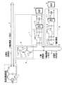
図1は、本発明に係る非接触給電装置及び非接触給電システムの実施の形態1の要部構成を示すブロック図である。この非接触給電システムは、高周波電源回路1(交流電源)が、例えば、自動倉庫内に敷設されたX軸給電線2に、所定周波数の高周波定電流を通流させる。X軸給電線2に通流する高周波定電流は、X軸受電部4(受電給電部)により非接触状態で電磁誘導により受電される。X軸受電部4は、X軸給電線2に沿って自在に移動させることが可能なように、X軸給電線2に付設されている。
Hereinafter, the present invention will be described with reference to the drawings showing embodiments thereof.
(Embodiment 1)
FIG. 1 is a block diagram showing the main configuration of
X軸受電部4は、X軸給電線2から受電した電力を高周波定電流に変換する定電流変換回路部6と、定電流変換回路部6に直列接続され、定電流変換回路部6が変換した高周波定電流を高周波定電圧に変換する定電圧変換回路7と、定電圧変換回路7が変換した高周波定電圧を整流するダイオードブリッジを含む整流回路10と、整流回路10の出力を平滑する平滑コンデンサ(平滑回路)C5とを備えている。平滑コンデンサC5が平滑した直流電力は、例えば自動倉庫内の搬送体を移動させる為のモータ等である負荷5に与えられる。
定電圧変換回路7は、2つの並列接続されたコンデンサC3,C4間にリアクトルL3が接続されたπ型のイミタンス変換回路(インピーダンス変換回路)である。
The X bearing
The constant
定電流変換回路部6が変換し、定電圧変換回路7を通流した高周波定電流は、例えばX軸給電線2に直交するY軸給電線3に与えられる。Y軸給電線3に通流する高周波定電流は、Y軸受電部8により非接触状態で電磁誘導により受電される。Y軸受電部8は、Y軸給電線3に沿って自在に移動させることが可能なように、Y軸給電線3に付設されている。
The high-frequency constant current converted by the constant current
Y軸受電部8は、Y軸給電線3に通流する高周波定電流に共振して受電するピックアップコイルL4及びコンデンサC6からなる並列共振回路と、この並列共振回路が受電した高周波電力を高周波定電圧に変換する定電圧変換回路とをそなえている。この定電圧変換回路は、2つの並列接続されたコンデンサC7,C8間にリアクトルL5が接続されたπ型のイミタンス変換回路である。
Y軸受電部8は、また、コンデンサC7,C8及びリアクトルL5からなる定電圧変換回路が変換した高周波定電圧を整流するダイオードブリッジを含む整流回路11と、整流回路11の出力を平滑する平滑コンデンサC9とを備えている。平滑コンデンサC9が平滑した直流電力は、例えば自動倉庫内の搬送体を移動させるモータ等である負荷9に与えられる。
The Y-bearing
The Y-bearing
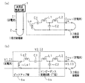
図2(a)は、X軸受電部4の定電流変換回路部6の内部構成を示す回路図である。定電流変換回路部6は、1段目給電線(X軸給電線)2に通流する高周波定電流に共振して受電するピックアップコイルLp及びコンデンサC1からなる直列共振回路と、この直列共振回路が受電した高周波定電圧を高周波定電流に変換する定電流変換回路とを備えている。
FIG. 2A is a circuit diagram showing an internal configuration of the constant current
この定電流変換回路は、コンデンサC1に直列接続された2つのリアクトルL1、L2間と、ピックアップコイルLpのコンデンサC1に接続されない端子との間にコンデンサC2が接続されたT型のイミタンス変換回路(インピーダンス変換回路)である。尚、この定電流変換回路は、他のイミタンス変換回路であっても良く、例えば、特開平8−305450号公報及び特開平10−91254号公報に開示されたようなインピーダンス変換器であっても良い。
コンデンサC2及びリアクトルL1、L2からなる定電流変換回路が変換した高周波定電流は、定電圧変換回路7を含む2段目給電線(Y軸給電線)3に与えられる。
This constant current conversion circuit is a T-type immittance conversion circuit in which a capacitor C2 is connected between two reactors L1 and L2 connected in series to the capacitor C1 and a terminal not connected to the capacitor C1 of the pickup coil Lp. Impedance conversion circuit). The constant current conversion circuit may be another immittance conversion circuit, for example, an impedance converter as disclosed in JP-A-8-305450 and JP-A-10-91254. good.
The high-frequency constant current converted by the constant current conversion circuit including the capacitor C2 and the reactors L1 and L2 is applied to the second-stage power supply line (Y-axis power supply line) 3 including the constant
以下に、このような構成の非接触給電システムの動作を説明する。
図2(a)に示す定電流変換回路部6のピックアップコイルLpを変圧器としてL型等価回路で表し、1次側には高周波定電流が供給されるので、1段目給電線(X軸給電線)2等を省略すると、図2(b)に示す等価回路になる。
ここで、Lp1はピックアップコイルLpの励磁インダクタンス、Lp2はピックアップコイルLpの漏れインダクタンス、V1は、励磁インダクタンスLp1の両端に印加される、Lp1,Lp2,C1からなるピックアップ部(定電圧変換回路)6aの入力電圧、I1は、ピックアップ部6aに入力される高周波定電流である。
Below, operation | movement of the non-contact electric power feeding system of such a structure is demonstrated.
The pickup coil Lp of the constant current
Here, Lp1 is an excitation inductance of the pickup coil Lp, Lp2 is a leakage inductance of the pickup coil Lp, V1 is a pickup unit (constant voltage conversion circuit) 6a composed of Lp1, Lp2, and C1 applied to both ends of the excitation inductance Lp1. The input voltage I1 is a high-frequency constant current input to the pickup unit 6a.
また、V2は、ピックアップ部6aの出力電圧であり、コンデンサC2及びリアクトルL1、L2からなるインピーダンス変換回路6bの入力電圧、I2は、ピックアップ部6aの出力電流であり、インピーダンス変換回路6bの入力電流、V3はインピーダンス変換回路6bの出力電圧、I3はインピーダンス変換回路6bの出力電流である。
ピックアップ部6aの入出力は、(1)式のようになる。(ωはピックアップ部6aの入力電圧V1の角周波数)
V2 is an output voltage of the pickup unit 6a, an input voltage of the
The input / output of the pickup unit 6a is as shown in equation (1). (Ω is the angular frequency of the input voltage V1 of the pickup unit 6a)

ここで、
1−ω2 (Lp1+Lp2)・C1=0(共振条件)
であれば、
I1=(1/jωLp1)・V2
∴V2=jωLp1・I1
よって、I1が定電流であることから、ピックアップ部6aの出力電圧V2は交流定電圧になる。
また、インピーダンス変換回路6bの入出力は、(2)式のようになる。
here,
1−ω 2 (Lp1 + Lp2) · C1 = 0 (resonance condition)
If,
I1 = (1 / jωLp1) · V2
∴V2 = jωLp1 ・ I1
Therefore, since I1 is a constant current, the output voltage V2 of the pickup unit 6a becomes an AC constant voltage.
Further, the input / output of the
ここで、
L1=L2
1−ω2 L1C2=0(共振条件)
であれば、
V2=jωL1・I3
∴I3=V2/jωL1
よって、V2が交流定電圧であることから、インピーダンス変換回路6bの出力電流I3は、インピーダンス変換回路6bの出力端子から見た負荷に関係なく交流定電流になる。
また、(1)(2)式より
here,
L1 = L2
1−ω 2 L1C2 = 0 (resonance condition)
If,
V2 = jωL1 · I3
∴I3 = V2 / jωL1
Therefore, since V2 is an AC constant voltage, the output current I3 of the
Also, from formulas (1) and (2)
I1=(L1/Lp1)・I3
∴I3=(Lp1/L1)・I1
よって、L1を適当に選択することにより、インピーダンス変換回路6bの出力電流I3を任意の交流定電流に設定することが出来る。
また、(2)式より
I2=jωC2・V3
ここで、インピーダンス変換回路6bの出力端子から見た負荷をRとすると、
I2=jωC2・R・I3
となり、I3が定電流であるから、ピックアップ部6aの出力電流I2は、負荷Rに正比例する。
I1 = (L1 / Lp1) · I3
∴I3 = (Lp1 / L1) · I1
Accordingly, by appropriately selecting L1, the output current I3 of the
Also, from equation (2), I2 = jωC2 · V3
Here, when the load viewed from the output terminal of the
I2 = jωC2, R, I3
Since I3 is a constant current, the output current I2 of the pickup unit 6a is directly proportional to the load R.
ところで、図2(b)に示す等価回路において、Lp2,C1,L1は、
ω(Lp2+L1)−1/ωC1
=(ω(Lp1+Lp2)−1/ωC1)+ω(L1−Lp1)
となる。ここで、第1項ω(Lp1+Lp2)−1/ωC1=0(共振条件)であるから、
ω(Lp2+L1)−1/ωC1=ω(L1−Lp1)
従って、ω(L1−Lp1)≧ωLp2 であれば、図3(a)の等価回路に示すように、C1,L1を
ωL1′=ω(L1−Lp1−Lp2)
となるインダクタンスL1′のみに代替させることが出来る。
In the equivalent circuit shown in FIG. 2B, Lp2, C1, and L1 are
ω (Lp2 + L1) -1 / ωC1
= (Ω (Lp1 + Lp2) -1 / ωC1) + ω (L1-Lp1)
It becomes. Here, since the first term ω (Lp1 + Lp2) −1 / ωC1 = 0 (resonance condition),
ω (Lp2 + L1) −1 / ωC1 = ω (L1−Lp1)
Therefore, if ω (L1−Lp1) ≧ ωLp2, as shown in the equivalent circuit of FIG. 3A, C1 and L1 are set to ωL1 ′ = ω (L1−Lp1−Lp2).
It is possible to substitute only the inductance L1 ′.
同様に、ω(L1−Lp1)<ωLp2 であれば、C1,L1を
ωC1′=1/ω(Lp1+Lp2−L1)
となるキャパシタンスC1′のみに代替させることが出来る。
また、同様に、C1,L1を、合成インピーダンスがω(L1−Lp1)となるようなインダクタンス及びキャパシタンスの組合せに代替させることも可能である。
Similarly, if ω (L1−Lp1) <ωLp2, C1 and L1 are set to ωC1 ′ = 1 / ω (Lp1 + Lp2−L1).
It is possible to substitute only the capacitance C1 ′.
Similarly, C1 and L1 can be replaced with a combination of inductance and capacitance such that the combined impedance is ω (L1−Lp1).
更に、図3(b)の等価回路に示すように、2段目給電線(Y軸給電線)3aが有するインダクタンスLf又はその一部に、L2を兼ねさせることが出来る。インダクタンスLfがL2より大きい場合は、図3(c)の等価回路に示すように、補償コンデンサCcを直列に接続し、Cc及びLfの合成インピーダンスがL2となるようにすることが可能である。
また、L2を、C2の2段目給電線3a側の、合成インピーダンスがL2となる全てのインダクタンス及びキャパシタンスの組合せに代替させることも可能である。
Further, as shown in the equivalent circuit of FIG. 3B, the inductance Lf or part of the inductance Lf of the second-stage power supply line (Y-axis power supply line) 3a can also serve as L2. When the inductance Lf is larger than L2, as shown in the equivalent circuit of FIG. 3C, it is possible to connect the compensation capacitor Cc in series so that the combined impedance of Cc and Lf becomes L2.
It is also possible to substitute L2 for all combinations of inductance and capacitance with a combined impedance of L2 on the second-stage feeder line 3a side of C2.
このような非接触給電システムでは、定電流変換回路部6のピックアップコイルLp及びコンデンサC1が、X軸給電線2に流れる高周波定電流に共振して高周波定電圧を受電する。この受電された高周波定電圧は、定電流変換回路部6のコンデンサC2及びリアクトルL1、L2からなるインピーダンス変換回路6bで、高周波定電流に変換され、定電圧変換回路7及びY軸給電線3に供給される。
In such a non-contact power supply system, the pickup coil Lp and the capacitor C1 of the constant current
定電圧変換回路7は、供給された高周波定電流を高周波定電圧に変換し、この変換された高周波定電圧電力は、整流回路10で整流され、平滑コンデンサC5で平滑されて、直流に変換され、負荷5に供給される。
一方、Y軸受電部8のピックアップコイルL4及びコンデンサC6は、Y軸給電線3に供給された高周波定電流に共振して受電し、この受電された電力は、コンデンサC7,C8及びリアクトルL5からなる定電圧変換回路で、高周波定電圧に変換される。この変換された高周波定電圧は、整流回路11で整流され、平滑コンデンサC9で平滑されて、直流に変換され、負荷9に供給される。
The constant
On the other hand, the pickup coil L4 and the capacitor C6 of the Y-bearing
(実施の形態2)
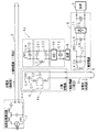
図4は、本発明に係る非接触給電装置及び非接触給電システムの実施の形態2の要部構成を示すブロック図である。この非接触給電システムは、X軸給電線2に通流する高周波定電流が、X軸受電部4aにより非接触状態で電磁誘導により受電される。X軸受電部4aは、X軸給電線2に沿って自在に移動させることが可能なように、X軸給電線2に付設されている。
(Embodiment 2)
FIG. 4 is a block diagram showing the main configuration of the second embodiment of the non-contact power supply apparatus and the non-contact power supply system according to the present invention. In this non-contact power supply system, a high-frequency constant current flowing through the X-axis
X軸受電部4aは、X軸給電線2から高周波定電圧を受電する定電圧変換回路(ピックアップ部)6aと、受電された高周波定電圧を高周波定電流に変換して、Y軸給電線3に供給する定電流変換回路6bと、定電圧変換回路6aに並列接続され、定電圧変換回路6aが受電した高周波定電圧を整流するダイオードブリッジを含む整流回路10と、整流回路10の出力を平滑する平滑コンデンサ(平滑回路)C5とを備えている。平滑コンデンサC5が平滑した直流電力は、例えば自動倉庫内の搬送体を移動させる為のモータ等である負荷5に与えられる。その他の構成は、上述した本発明に係る非接触給電装置及び非接触給電システムの実施の形態1の要部構成と同様であるので、同一箇所には同一符号を付加して、説明を省略する。
The X-bearing power supply unit 4a converts the received high-frequency constant voltage into a high-frequency constant current, and converts the received high-frequency constant voltage into a high-frequency constant current. A constant
このような構成の非接触給電システムでは、定電圧変換回路6aのピックアップコイルLp及びコンデンサC1が、X軸給電線2に流れる高周波定電流に共振して高周波定電圧を受電する。この受電された高周波定電圧は、定電流変換回路6bのコンデンサC2及びリアクトルL1、L2からなるインピーダンス変換回路で、高周波定電流に変換され、Y軸給電線3に供給される。
定電圧変換回路6aで受電した高周波定電圧は、整流回路10で整流され、平滑コンデンサC5で平滑されて、直流電力に変換され、負荷5に供給される。その他の動作は、上述した本発明に係る非接触給電装置及び非接触給電システムの実施の形態1の動作と同様であるので、説明を省略する。
In the non-contact power supply system having such a configuration, the pickup coil Lp and the capacitor C1 of the constant voltage conversion circuit 6a resonate with the high frequency constant current flowing through the X-axis
The high frequency constant voltage received by the constant voltage conversion circuit 6 a is rectified by the
(実施の形態3)
図5は、本発明に係る非接触給電装置及び非接触給電システムの実施の形態3の要部構成を示すブロック図である。この非接触給電システムは、X軸給電線2に通流する高周波定電流が、X軸受電部4b、4cにより非接触状態で電磁誘導により受電される。X軸受電部4b,4cは、X軸給電線2に沿って一体となって自在に移動させることが可能なように、X軸給電線2にそれぞれ付設されている。
(Embodiment 3)
FIG. 5 is a block diagram showing a main configuration of a third embodiment of the non-contact power feeding device and the non-contact power feeding system according to the present invention. In this non-contact power supply system, a high-frequency constant current that flows through the X-axis
X軸受電部4bは、X軸給電線2から受電した高周波定電圧を高周波定電流に変換し、Y軸給電線3に供給する定電流変換回路部6を備えている。
X軸受電部4cは、X軸給電線2に通流する高周波定電流に共振して受電するピックアップコイルL6及びコンデンサC10からなる並列共振回路と、この並列共振回路が受電した高周波電力を高周波定電圧に変換する定電圧変換回路とをそなえている。この定電圧変換回路は、2つの並列接続されたコンデンサC11,C12間にリアクトルL7が接続されたπ型のイミタンス変換回路である。
The X
The X-bearing power section 4c is a high-frequency constant circuit that includes a parallel resonant circuit including a pickup coil L6 and a capacitor C10 that receive power by resonating with a high-frequency constant current flowing through the
X軸受電部4cは、また、コンデンサC11,C12及びリアクトルL7からなる定電圧変換回路が変換した高周波定電圧を整流するダイオードブリッジを含む整流回路10と、整流回路10が整流した出力を平滑する平滑コンデンサC13とを備えている。平滑コンデンサC13が平滑した直流電力は、例えば自動倉庫内の搬送体を移動させる為のモータ等である負荷5に与えられる。その他の構成は、上述した本発明に係る非接触給電装置及び非接触給電システムの実施の形態1の要部構成と同様であるので、同一箇所には同一符号を付加して、説明を省略する。
The X-bearing electrical unit 4c also smoothes the output rectified by the
このような構成の非接触給電システムでは、定電流変換回路部6が、X軸給電線2に流れる高周波定電流に共振して電力を受電し、高周波定電流電力に変換して、Y軸給電線3に供給する。
X軸受電部4cのピックアップコイルL6及びコンデンサC10からなる並列共振回路で受電された高周波電力が、コンデンサC11,C12及びリアクトルL7からなる定電圧変換回路で高周波定電圧に変換される。変換された高周波定電圧は、整流回路10で整流され、平滑コンデンサC13で平滑されて、直流電力に変換され、負荷5に供給される。その他の動作は、上述した本発明に係る非接触給電装置及び非接触給電システムの実施の形態1の動作と同様であるので、説明を省略する。
In the non-contact power supply system having such a configuration, the constant current
The high frequency power received by the parallel resonance circuit composed of the pickup coil L6 and the capacitor C10 of the X-bearing electric section 4c is converted into a high frequency constant voltage by the constant voltage conversion circuit composed of the capacitors C11 and C12 and the reactor L7. The converted high frequency constant voltage is rectified by the
(実施の形態4)
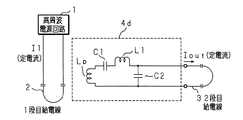
図6は、本発明に係る非接触給電装置及び非接触給電システムの実施の形態4の要部構成を示すブロック図である。この非接触給電システムは、高周波電源回路1(交流電源)が、例えば、自動倉庫内に敷設された1段目給電線2に、所定周波数の高周波定電流I1を通流させる。1段目給電線2に通流する高周波定電流I1は、受電部4d(受電給電部)により非接触状態で電磁誘導により受電される。受電部4dは、1段目給電線2に沿って自在に移動させることが可能なように、1段目給電線2に付設されている。
(Embodiment 4)
FIG. 6 is a block diagram showing a main configuration of the fourth embodiment of the non-contact power supply apparatus and the non-contact power supply system according to the present invention. In this non-contact power supply system, a high-frequency power circuit 1 (AC power supply) causes a high-frequency constant current I1 having a predetermined frequency to flow through, for example, a first-stage
受電部4dは、ピックアップコイルLp、コンデンサC1及びリアクトルL1の直列回路とコンデンサC2とが並列接続された並列共振回路が、1段目給電線2に通流する高周波定電流に共振して受電する。受電部4dが受電した高周波定電流は、2段目給電線3に供給される。
The
以下に、このような構成の非接触給電システムの動作を説明する。
受電部4dの共振条件は
(ωLp+ωL1−1/ωC1)−1/ωC2=0(ωは受電部4dの入力電圧V1の角周波数)
であるから、
ω(Lp+L1)−(C1+C2)/ωC1C2=0
Below, operation | movement of the non-contact electric power feeding system of such a structure is demonstrated.
The resonance condition of the
Because
ω (Lp + L1) − (C1 + C2) / ωC1C2 = 0
図6に示すピックアップコイルLpを変圧器としてL型等価回路で表し、1次側には高周波定電流が供給されるので、1段目給電線2等を省略すると、図7に示す等価回路になる。
ここで、Lp1はピックアップコイルLpの励磁インダクタンス、Lp2はピックアップコイルLpの漏れインダクタンス、V1は、励磁インダクタンスLp1の両端に印加される、Lp1,Lp2,C1,L1,C2からなる受電部4dへの入力電圧、I1は、受電部4dに入力される高周波定電流である。
また、V2は、受電部4dの出力電圧であり、I2は、受電部4dの出力電流である。
The pickup coil Lp shown in FIG. 6 is represented by an L-type equivalent circuit using a transformer, and a high-frequency constant current is supplied to the primary side. Therefore, if the first-
Here, Lp1 is an excitation inductance of the pickup coil Lp, Lp2 is a leakage inductance of the pickup coil Lp, V1 is applied to both ends of the excitation inductance Lp1, and is supplied to the
V2 is an output voltage of the
ここで、
ωLp2−1/ωC1+ωL1=ωLp2′
とすると、受電部4dの入出力は、(4)式のようになる。
here,
ωLp2-1 / ωC1 + ωL1 = ωLp2 ′
Then, the input / output of the
(4)式から、
I1=((L1+Lp2′)/L1)・I2
よって、受電部4dの入力電流I1が交流定電流であることから、受電部4dの出力電流I2も交流定電流になり、コンデンサC1及びリアクトルL1を適当に選ぶことにより、受電部4dの出力定電流を任意に設定することが可能である。
From equation (4)
I1 = ((L1 + Lp2 ′) / L1) · I2
Therefore, since the input current I1 of the
尚、上述した各実施の形態では、高周波定電流が供給される給電線(2)から受電した電力による交流定電流を更に他の給電線(3)に供給する受電部を、1段備える構成であるが、このような受電部を複数段備える構成とすることも可能であることは言うまでもない。 In each of the above-described embodiments, the power receiving unit that supplies the AC constant current generated by the power received from the power supply line (2) supplied with the high-frequency constant current to the other power supply line (3) is provided in one stage. However, it goes without saying that it is also possible to employ a configuration in which a plurality of such power reception units are provided.
1 高周波電源回路(交流電源)
2 X軸給電線(1段目給電線)
3 Y軸給電線(2段目給電線)
4〜4c X軸受電部(受電給電部)
4d 受電部(受電給電部)
5,9 負荷
6 定電流変換回路部
6a 定電圧変換回路(ピックアップ部)
6b 定電流変換回路
7 定電圧変換回路
8 Y軸受電部
10,11 整流回路
C1〜C4,C6〜C8,C10〜C12 コンデンサ
C5 平滑コンデンサ(平滑回路)
C9,C13 平滑コンデンサ
L1〜L3,L5,L7 リアクトル
L4,L6,Lp ピックアップコイル
1 High frequency power supply circuit (AC power supply)
2 X-axis feed line (first stage feed line)
3 Y-axis feed line (second stage feed line)
4-4c X-bearing power section (power receiving and feeding section)
4d Power receiving unit (power receiving unit)
5,9
6b Constant
C9, C13 Smoothing capacitor L1-L3, L5, L7 Reactor L4, L6, Lp Pickup coil
Claims (5)
前記受電給電部は、交流定電流に共振して受電する受電回路と、該受電回路が共振して受電した交流電力を、交流定電流に変換する定電流変換回路とを備え、該定電流変換回路が変換した交流定電流を、前記他の給電線に供給するように構成してあることを特徴とする非接触給電装置。 Non-contact power supply comprising one or a plurality of power receiving power supply units that receive power by resonating with the AC constant current in a contactless manner from a power supply line to which an AC constant current is supplied and supply the received power to another power supply line In the device
The power receiving and feeding unit includes a power receiving circuit that receives power by resonating with an AC constant current, and a constant current conversion circuit that converts AC power received by resonance with the power receiving circuit into an AC constant current. A non-contact power feeding apparatus configured to supply an AC constant current converted by a circuit to the other power feeding line.
前記受電給電部は、ピックアップコイル、第1コンデンサ及びリアクトルの直列回路と第2コンデンサとが並列接続された並列共振回路であり、該並列共振回路は、共振して受電した交流電力を交流定電流に変換して前記他の給電線に供給するように構成してあることを特徴とする非接触給電装置。 Non-contact power supply comprising one or a plurality of power receiving power supply units that receive power by resonating with the AC constant current in a contactless manner from a power supply line to which an AC constant current is supplied and supply the received power to another power supply line In the device
The power receiving / feeding unit is a parallel resonant circuit in which a series circuit of a pickup coil, a first capacitor and a reactor, and a second capacitor are connected in parallel, and the parallel resonant circuit receives AC power that has been resonated and received as an AC constant current. It is comprised so that it may convert into and supply to said other electric power feeding line, The non-contact electric power feeder characterized by the above-mentioned.
Priority Applications (1)
| Application Number | Priority Date | Filing Date | Title |
|---|---|---|---|
| JP2005018608A JP4455355B2 (en) | 2005-01-26 | 2005-01-26 | Non-contact power supply device and non-contact power supply system |
Applications Claiming Priority (1)
| Application Number | Priority Date | Filing Date | Title |
|---|---|---|---|
| JP2005018608A JP4455355B2 (en) | 2005-01-26 | 2005-01-26 | Non-contact power supply device and non-contact power supply system |
Publications (2)
| Publication Number | Publication Date |
|---|---|
| JP2006211784A JP2006211784A (en) | 2006-08-10 |
| JP4455355B2 true JP4455355B2 (en) | 2010-04-21 |
Family
ID=36968021
Family Applications (1)
| Application Number | Title | Priority Date | Filing Date |
|---|---|---|---|
| JP2005018608A Expired - Fee Related JP4455355B2 (en) | 2005-01-26 | 2005-01-26 | Non-contact power supply device and non-contact power supply system |
Country Status (1)
| Country | Link |
|---|---|
| JP (1) | JP4455355B2 (en) |
Families Citing this family (7)
| Publication number | Priority date | Publication date | Assignee | Title |
|---|---|---|---|---|
| JP2008273434A (en) * | 2007-05-01 | 2008-11-13 | Murata Mach Ltd | Non-contact electric supply system and its extending method |
| WO2014010057A1 (en) * | 2012-07-12 | 2014-01-16 | 富士機械製造株式会社 | Contactless electrical power supply device |
| JP2017093180A (en) * | 2015-11-11 | 2017-05-25 | 株式会社ダイヘン | Noncontact power transmission system, and power transmission device |
| JP6515015B2 (en) * | 2015-11-11 | 2019-05-15 | 株式会社ダイヘン | Contactless power transmission system |
| JP6487825B2 (en) * | 2015-11-11 | 2019-03-20 | 株式会社ダイヘン | Non-contact power transmission system and power transmission device |
| JP6983557B2 (en) * | 2017-07-12 | 2021-12-17 | 株式会社ダイヘン | Contactless power transfer system |
| JP2020195223A (en) * | 2019-05-29 | 2020-12-03 | 長野日本無線株式会社 | Non-contact power supply system |
-
2005
- 2005-01-26 JP JP2005018608A patent/JP4455355B2/en not_active Expired - Fee Related
Also Published As
| Publication number | Publication date |
|---|---|
| JP2006211784A (en) | 2006-08-10 |
Similar Documents
| Publication | Publication Date | Title |
|---|---|---|
| JP4455355B2 (en) | Non-contact power supply device and non-contact power supply system | |
| JP4941418B2 (en) | Non-contact power transmission device | |
| JP4815499B2 (en) | Non-contact power transmission circuit | |
| JP6323312B2 (en) | Contactless power supply system | |
| JP6070650B2 (en) | Power transmission device, power reception device, and vehicle equipped with the same | |
| JP2008259419A (en) | Noncontact feeder system | |
| JP5862844B2 (en) | Wireless power transmission system | |
| JP2017070055A (en) | Wireless power transmission system and power transmission device | |
| JP2019022265A (en) | Non-contact power transmission system | |
| JP2007089279A (en) | Noncontact feeder system | |
| KR101031278B1 (en) | Isolated DC/DC converter using full-bridge topology | |
| JP5217324B2 (en) | Power supply system | |
| EP2922725B1 (en) | Circuit arrangement for providing a dc voltage in a vehicle and method of operating a circuit arrangement | |
| US20180269796A1 (en) | Electric power conversion device | |
| CN110336389B (en) | Wireless power receiving device and wireless power transmission system | |
| JP6308310B2 (en) | Contactless power supply | |
| US20160261195A1 (en) | Electric power conversion device | |
| JP2008104319A (en) | Noncontact power transmission device | |
| CN111279579A (en) | Resonant tank circuit for transmitting electrical energy | |
| JP4293854B2 (en) | Non-contact power receiving device and moving body | |
| JP2005027400A (en) | Noncontact power receiving unit | |
| JP2015156741A (en) | Power transmission system, power receiver, and power transmitter | |
| JP6164413B2 (en) | Power supply device and method for improving power supply device | |
| CN109196767A (en) | power control circuit | |
| CN111247713A (en) | Resonant circuit for transmitting electrical energy without power amplifier |
Legal Events
| Date | Code | Title | Description |
|---|---|---|---|
| A621 | Written request for application examination |
Free format text: JAPANESE INTERMEDIATE CODE: A621 Effective date: 20071214 |
|
| TRDD | Decision of grant or rejection written | ||
| A01 | Written decision to grant a patent or to grant a registration (utility model) |
Free format text: JAPANESE INTERMEDIATE CODE: A01 Effective date: 20100202 |
|
| A01 | Written decision to grant a patent or to grant a registration (utility model) |
Free format text: JAPANESE INTERMEDIATE CODE: A01 |
|
| A61 | First payment of annual fees (during grant procedure) |
Free format text: JAPANESE INTERMEDIATE CODE: A61 Effective date: 20100203 |
|
| FPAY | Renewal fee payment (event date is renewal date of database) |
Free format text: PAYMENT UNTIL: 20130212 Year of fee payment: 3 |
|
| R150 | Certificate of patent or registration of utility model |
Free format text: JAPANESE INTERMEDIATE CODE: R150 |
|
| FPAY | Renewal fee payment (event date is renewal date of database) |
Free format text: PAYMENT UNTIL: 20140212 Year of fee payment: 4 |
|
| LAPS | Cancellation because of no payment of annual fees |