JP4455116B2 - Belt shift control mechanism and fixing device - Google Patents
Belt shift control mechanism and fixing device Download PDFInfo
- Publication number
- JP4455116B2 JP4455116B2 JP2004095869A JP2004095869A JP4455116B2 JP 4455116 B2 JP4455116 B2 JP 4455116B2 JP 2004095869 A JP2004095869 A JP 2004095869A JP 2004095869 A JP2004095869 A JP 2004095869A JP 4455116 B2 JP4455116 B2 JP 4455116B2
- Authority
- JP
- Japan
- Prior art keywords
- belt
- roller
- fixing
- pressure plate
- gear
- Prior art date
- Legal status (The legal status is an assumption and is not a legal conclusion. Google has not performed a legal analysis and makes no representation as to the accuracy of the status listed.)
- Expired - Fee Related
Links
Images


Description
本発明は、例えば、電子写真装置(プリンター・複写機・ファクシミリなど)等の画像形成装置に搭載されるベルト方式の定着装置に適用して有効なベルト寄り制御機構に関する。また、ベルト方式の定着装置に関する。 The present invention may, for example, an electrophotographic apparatus effective belt deviation control mechanism applied to the fixing device of the belt type to be mounted on (printer copier, facsimile, etc.) the image forming apparatus or the like. The present invention also relates to a belt type fixing device.
従来、電子写真装置等において、記録材上にのせたトナーを加熱・加圧して溶融し、定着させる熱圧式定着装置には、大別すると、一対のローラーを対向圧接させ、そのローラーのいずれか、もしくは両方の内部に加熱源を配置し、その圧接部に記録材を挟持搬送させて定着処理を行うローラー方式の定着装置(ローラー定着)と、片方がローラー、もう片方がベルトで構成される所謂ベルト方式の定着装置(ベルト定着)の2種類が存在する。 Conventionally, in an electrophotographic apparatus or the like, a heat-pressure type fixing apparatus that heats, pressurizes, melts, and fixes toner on a recording material is roughly classified. Alternatively, a heat source is arranged in both of them, and a roller type fixing device (roller fixing) that performs a fixing process by sandwiching and transporting a recording material in the pressure contact portion, and one is constituted by a roller and the other is constituted by a belt. There are two types of so-called belt type fixing devices (belt fixing).
ローラー定着は、所定の定着温度に温調された定着ローラー(ヒートローラー)と、これに圧接する加圧ローラーとのローラー対を基本構成とするものであり、該ローラー対を回転させ、該ローラー対の圧接部である定着ニップ部に未定着トナー像が形成された記録材を導入して挟持搬送させて、定着ローラーの熱と、定着ニップ部圧で未定着トナー像を記録材に熱圧定着させるものである。 The roller fixing is basically composed of a roller pair of a fixing roller (heat roller) whose temperature is adjusted to a predetermined fixing temperature and a pressure roller pressed against the fixing roller, and the roller pair is rotated to rotate the roller. A recording material on which an unfixed toner image is formed is introduced into a fixing nip portion, which is a pair of pressure contact portions, and is nipped and conveyed, and the unfixed toner image is applied to the recording material by the heat of the fixing roller and the fixing nip portion pressure. It is to fix.
ここで、未定着トナー像ののった記録材に与えられる熱量は、定着ローラーおよび加圧ローラーの温度と、記録材が定着ニップ部に通過する時間、つまり定着ニップ幅と記録材の進行速度に依存する。定着ニップ幅とは、定着ニップ部の記録材進行方向の長さのことを指す。 Here, the amount of heat given to the recording material with the unfixed toner image is determined by the temperature of the fixing roller and the pressure roller, the time for the recording material to pass through the fixing nip portion, that is, the fixing nip width and the recording material traveling speed. Depends on. The fixing nip width refers to the length of the fixing nip portion in the recording material traveling direction.
より高速なプロセススピードを持つ電子写真装置等に搭載させる定着装置としては上記の熱量の関係からより定着ニップ幅の広い定着装置が必要とされる。ローラー定着において定着ニップ幅を広くするにはローラーの大径化が必要であり、ローラーを大径化すると、ローラーの熱容量が大きくなり、ローラーのヒートアップ時間(ウォームアップタイム)が長くなる等の問題がある。 As a fixing device to be mounted on an electrophotographic apparatus or the like having a higher process speed, a fixing device having a wider fixing nip width is required because of the above heat quantity. In order to widen the fixing nip width in roller fixing, it is necessary to increase the diameter of the roller. If the diameter of the roller is increased, the heat capacity of the roller increases and the heat-up time (warm-up time) of the roller becomes longer. There's a problem.
そこで、ローラーの大径化することなしに、広い定着ニップ幅を確保できる定着装置構成として、例えば特許文献1においてベルト方式の熱圧定着装置、いわゆるベルト定着が提案されている。 Therefore, as a fixing device configuration that can ensure a wide fixing nip width without increasing the diameter of the roller, for example, Patent Document 1 proposes a belt-type hot-pressure fixing device, so-called belt fixing.
ベルト定着は、加熱用回転体である定着ローラーに対して、複数のベルト張架部材間に張架させた耐熱性・可撓性のエンドレスベルトを加圧接触させて定着ニップ部を形成させ、該定着ニップ部に未定着トナー像を担持させた記録材を挟持搬送させることで、定着ローラーの熱と、定着ニップ部圧で未定着トナー像を記録材に熱圧定着させるものである。このベルト方式の定着装置は、定着ニップ幅をエンドレスベルトの定着ローラーに対する腹当て幅の調整により容易に大きく設定することが可能である。また、定着ニップ部幅を定着ローラーの径に依存させずに確保できるため、定着ローラーを小径、小熱容量にすることが可能となり、立ち上げ時間を短縮できる。定着ニップ幅を広くとれるため、記録材上のトナーをより溶融でき、カラー画像形成装置のように多量のトナーを使用する画像形成装置には適した定着装置である。 In belt fixing, a fixing nip portion is formed by press-contacting a heat-resistant / flexible endless belt stretched between a plurality of belt stretching members against a fixing roller which is a rotating body for heating, The recording material carrying the unfixed toner image is nipped and conveyed to the fixing nip portion, whereby the unfixed toner image is fixed to the recording material by heat and pressure with the heat of the fixing roller and the fixing nip portion pressure. In this belt-type fixing device, the fixing nip width can be easily set large by adjusting the width of the endless belt against the fixing roller of the endless belt. Further, since the fixing nip width can be secured without depending on the diameter of the fixing roller, the fixing roller can have a small diameter and a small heat capacity, and the start-up time can be shortened. Since the fixing nip width can be widened, the toner on the recording material can be melted more, and the fixing device is suitable for an image forming apparatus using a large amount of toner such as a color image forming apparatus.
図16はベルト方式の定着装置5の一例の概略構成模型図である。この定着装置5において、510は回転自在に配置された定着用回転体である定着ローラーである。この定着ローラー510は図示しない駆動源により矢印Aの時計方向に回転駆動され、内部に配置されたハロゲンヒーター520により加熱される。定着ローラー510の表面温度が定着ローラー表面に配置されたサーミスター525により検知され、その検知温度が所定の定着温度に維持されるように図示しない温調回路部によりハロゲンヒーター520に対する供給電力が制御されて、定着ローラー510の表面温度が所定の定着温度に温調管理される。
FIG. 16 is a schematic configuration diagram of an example of the belt-
また、上記定着ローラー510の下方にはベルトユニット53が配置されている。このベルトユニット53において、531はエンドレスである定着ベルトである。この定着ベルト531は、複数のベルト張架部材としての、入り口ローラー532、分離ローラー533、ベルト寄り補正ローラーとしてのステアリングローラー534により張架されている。
A
分離ローラー533はSUS等の金属からなり矢印SF方向に移動付勢されて定着ベルト531を介して定着ローラー510と圧接している。
The
ステアリングローラー534は揺動部材として一端側は矢印B方向に移動可能となっていて、定着ベルト531の寄りを修正する機能を有している。
The
また、入り口ローラー532と分離ローラー533の間には加圧パッド部540が配置されている。加圧パッド部540はSUS等の金属からなるベース541とシリコンゴム等からなる加圧パッド542、加圧パッド542と定着ベルト531の間に配置されたPIフィルム等からなる摺動シート543から構成され、矢印PF方向に移動付勢されて定着ベルト531を介して定着ローラー510に圧接している。上記の、定着ローラー510と、定着ベルト531、加圧パッド部540、分離ローラー533とにより定着ニップ部Wを形成している。定着ベルト531は定着ローラー510の回転に従動して矢印C方向に回転状態になる。
A
また、入り口ローラー532と加圧パッド部540の間にはオイルフェルト536が設けられている。オイルフェルト536にはシリコンオイルが含浸されていて定着ベルト531の内面にオイルを塗布し定着ベルト531と摺動シート543との摩擦力を低減している。
An oil felt 536 is provided between the
定着ローラー510が回転駆動され、それに伴い定着ベルト531も従動回転し、また定着ローラー510がハロゲンヒーター520により加熱され、所定の定着温度に温調された状態において、ベルトユニット53の入り口ローラー532側から定着ニップ部Wに未定着トナー像tを担持した記録材(記録紙)Pが導入されて定着ニップ部Wを挟持搬送されていく。この挟持搬送過程で記録材Pの未定着トナー像面が定着ローラー510の表面に密着してトナー像が定着ローラー510の熱で加熱され、記録材Pの面に加熱加圧定着される。記録材Pは定着ニップ部Wのシート出口部において定着ローラー510の弾性層に対する分離ローラー533の食い込み(進入)により定着ローラー510の表面より分離されて排出搬送されていく。
When the
このようなベルト方式の定着装置5は、ローラー定着よりも定着ニップ幅を広くとれるため、記録材上のトナーをより溶融でき、カラー画像形成装置における多量のトナーを使用する画像形成装置には適した構成である。
The
上記構成において、定着ベルト531はその回転過程において該ベルトの張架部材としての入り口ローラー532・分離ローラー533・ステアリングローラー534の軸線方向(ローラー長手方向、あるいはベルト移動方向を横切るベルト幅方向)の一方側又は他方側にローラーに沿って大なり小なり片寄り移動する現象を生じる。これは複数のベルト張架部材間の並行度やねじれ等が原因しているもので,これらの精度を高めるのは限界があり、精度向上だけでは上記のベルト片寄り移動を無くす(ベルトの走行安定化)ことは困難である。
In the above-described configuration, the
そこで複数のベルト張架部材の少なくとも1つのベルト張架部材を揺動部材として他のベルト張架部材に対する相対位置を変位させる(並行度やねじれを変化させる)ことで、回転時のベルトのベルト張架部材軸線方向への寄り移動を制御するベルト寄り制御機構がある。 Therefore, by rotating at least one belt stretching member of the plurality of belt stretching members as a swinging member and displacing the relative position with respect to other belt stretching members (changing parallelism and twist), the belt of the belt during rotation There is a belt shift control mechanism that controls shift movement in the axial direction of the tension member.
図16のベルト方式の定着装置5においては、ステアリングローラー534を補正ローラー(揺動部材)としてこれを揺動制御して、ベルトの寄り方向を交互に変更修正してベルト寄り移動を所定の移動領域幅内に納めるようにしている。
In the belt-
この方式は特許文献2に示されているようにベルトの位置検出手段によりベルトの片寄りが発生した場合は補正ローラー534の片側をB方向に移動させてベルトの寄り方向を交互に変更修正してベルト寄り移動を所定の移動領域幅内に納める方式が提案されている。
In this method, as shown in Patent Document 2, when a belt deviation occurs by the belt position detecting means, one side of the
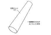
しかしながら、この方式ではベルトの一端側のみで補正ローラーの位置が変わるため図17に示すようなベルト531の一端側の開口が徐々に広くなっていくことがあった。特にベルト方式定着装置では、定着ベルト531に100℃以上の熱が加えられるために材料が変形しやすく、また、前記特許文献1の転写ベルトとは周長が大きく違うため前記図16で示す定着装置5ではステアリングローラー534を移動させると図17に示すように定着ベルト531の片側のみが広がってしまうことがより顕著であった。
However, in this method, since the position of the correction roller changes only at one end side of the belt, the opening at one end side of the
寄りを制御するためには図17のように定着ベルト531の前と奥の周長が異なってしまうとステアリングローラー534を移動させることで寄りを制御することが難しくなってしまう。
In order to control the deviation, as shown in FIG. 17, if the circumferences of the front and back of the
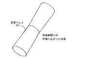
この対策としてステアリングローラー534の両端を各々逆方向に移動させることで図18に示すように定着ベルト534の両端が同等に広がる構成が提案されている。このステアリングローラーの駆動方式としては特許文献3に示すようにローラー保持部材の中央部に支点軸を持ち、この支点軸を中心にベルトの寄りを制御するローラーを回転させる方式が提案されている。
しかし特許文献3の方式ではローラーの両端を保持するローラー保持部材が必要となり、さらにローラー中央部に支点軸を持つためその支点軸保持部材もその両端がベルトの外側に配置される部材に固定される必要があった。そのため、これらの部品を配置するためには装置の小型化に大きな妨げになっていた。
However, the method of
本発明は上記に鑑みて提案されたもので、ベルト寄りを、ベルト内部に配置されたローラーの前奥(手前側端部と奥側端部の両端部)の位置を変化させて制御するベルト寄り制御機構およびベルト寄り制御機構を備えたベルト方式の定着装置において、ベルトの進行方向に対してローラーの前奥の位置を互いに逆方向に移動させる機構の小型化を図ることを目的とする。 The present invention has been proposed in view of the above, and a belt that controls the belt shift by changing the position of the front back (both ends of the front side end and the back end) of a roller disposed inside the belt. An object of the present invention is to reduce the size of a mechanism for moving the positions of the front and back of a roller in opposite directions with respect to the traveling direction of a belt in a belt-type fixing device including a shift control mechanism and a belt shift control mechanism.
本発明は下記の構成を特徴とするベルト寄り制御機構および定着装置である。 The present invention is a belt shift control mechanism and a fixing device characterized by the following configurations.
(1) 複数のベルト張架ローラーの間に張架されて回転するエンドレスのベルトを有するベルト機構の1つのベルト張架ローラーを揺動部材にして他のベルト張架ローラーに対する相対位置を変位させることで、回転時のベルトのベルト張架ローラー軸線方向への寄り移動を制御するベルト寄り制御機構において、
回動可能に支持された制御軸と、
前記制御軸の一端部に、前記制御軸に対して回転可能に支持された、前記揺動部材の一端部側を保持する第一の保持部材であって、第一の被駆動ギアが形成された第一の保持部材と、
前記制御軸の他端部に固定支持された、前記揺動部材の他端部側を保持する第二の保持部材と、
前記制御軸に第一の保持部材と隣接して固定支持された制御アームであって、第二の被駆動ギアが形成された制御アームと、
前記制御アームの前記第二の被駆動ギアと噛合するアイドラーギアと、
前記第一の保持部材の前記第一の被駆動ギア及び前記アイドラーギアと噛合して、回転することにより前記第一の保持部材及び前記制御アームを互いに逆方向に回転させる入力ギアと、
を有し、前記入力ギアの回転によって前記第一と第二の保持部材が前記制御軸の軸線を中心に互いに逆方向に回転動作することにより、前記揺動部材の両端が互いに逆方向に変位することを特徴とするベルト寄り制御機構。
(1) by a plurality of one belt-stretching roller belt mechanism having an endless belt that rotates being stretched between the belt-stretching roller to the swing member to displace the relative position with respect to the other of the belt-stretching roller In the belt shift control mechanism that controls the shift movement of the belt in the axial direction of the belt stretching roller during rotation,
A control shaft that is rotatably supported,
A first holding member , which is supported at one end of the control shaft so as to be rotatable with respect to the control shaft and holds one end of the swinging member, is formed with a first driven gear. A first holding member ;
A second holding member that is fixedly supported on the other end of the control shaft and holds the other end of the swing member;
A control arm fixedly supported adjacent to the first holding member on the control shaft, wherein the control arm is formed with a second driven gear ;
An idler gear meshing with the second driven gear of the control arm;
An input gear that meshes with the first driven gear and the idler gear of the first holding member and rotates the first holding member and the control arm in opposite directions by rotating ;
Has a displacement by said first and second holding member by the rotation of the input gear to rotate in the opposite directions about the axis of the control shaft, the ends opposite directions of the swing member A belt shift control mechanism.
(2)回転可能な定着ローラーと、前記定着ローラーを加熱する加熱手段と、複数のベルト張架ローラーの間に張架されて回転するエンドレスのベルトの外側を前記定着ローラーに圧接させて定着ニップ部を形成するベルト機構と、前記ベルト機構の1つのベルト張架ローラーを揺動部材にして他のベルト張架ローラーに対する相対位置を変位させることで、回転時のベルトのベルト張架ローラー軸線方向への寄り移動を制御するベルト寄り制御機構と、を有し、前記定着ニップ部に未定着トナー像を担持させた記録材を挟持搬送させてトナー像を定着する定着装置であって、
前記ベルト寄り制御機構は(1)に記載のベルト寄り制御機構であり、
前記ベルトの内側に設けられ、前記定着ローラーにベルトを圧接する加圧部材と、
前記ベルト寄り制御機構における制御軸の一端部側と他端部側で前記加圧部材を前記定着ローラーに向けて夫々加圧する第一の加圧板と第二の加圧板と、
前記定着ローラーに前記ベルトを選択的に加圧、加圧解除するために、前記第一の加圧板と第二の加圧板を前記ベルト寄り制御機構における入力ギアの回動中心と同軸に回動可能に支持した回動軸と、
回転駆動力を発生する駆動モーターと、
前記駆動モーターの駆動力を前記ベルト寄り制御機構における入力ギアに伝達する中継ギアと、
を有し、
前記ベルト寄り制御機構における制御軸の一端は前記第一の加圧板に回動可能に支持され、他端は前記第二の加圧板に回動可能に支持され、前記ベルト寄り制御機構における入力ギア及びアイドラーギアは前記第一の加圧板に回動可能に支持されていることを特徴とする定着装置。
(2) A rotatable fixing roller, a heating unit that heats the fixing roller, and an outer endless belt that is stretched and rotated between a plurality of belt stretching rollers, and presses the outer side of the endless belt against the fixing roller to fix the fixing nip. The belt mechanism that forms the belt and the belt tension roller axial direction of the belt during rotation by displacing the relative position of the belt mechanism relative to the other belt tension roller with one belt tension roller of the belt mechanism as a rocking member A fixing device for fixing a toner image by sandwiching and transporting a recording material carrying an unfixed toner image in the fixing nip portion.
The belt shift control mechanism is the belt shift control mechanism described in (1),
A pressure member that is provided inside the belt and presses the belt against the fixing roller;
A first pressure plate and a second pressure plate that pressurize the pressure member toward the fixing roller on one end side and the other end side of the control shaft in the belt shift control mechanism,
In order to selectively pressurize and release the belt from the fixing roller, the first pressure plate and the second pressure plate are rotated coaxially with the rotation center of the input gear in the belt shift control mechanism. A pivot shaft supported in a possible manner;
A drive motor that generates rotational drive force;
A relay gear that transmits the driving force of the drive motor to the input gear in the belt shift control mechanism;
Have
One end of a control shaft in the belt shift control mechanism is rotatably supported by the first pressure plate, and the other end is rotatably supported by the second pressure plate, and an input gear in the belt shift control mechanism. And the idler gear is rotatably supported by the first pressure plate.
即ち、揺動部材の一端部側と他端部側を互いに逆方向に揺動変位させる第一の保持部材と第二の保持部材は制御軸のみで連結されているため、特に従来例のような第一の保持部材と第二の保持部材の中央部に支軸を有したり、その支軸を支持する部材等が不要となり装置の小型化を容易に実現できる構成となっている。 That is, the first holding member and the second holding member that swing and displace the one end side and the other end side of the swing member in opposite directions are connected only by the control shaft. The first holding member and the second holding member have a support shaft at the center, or a member for supporting the support shaft is not required, and the apparatus can be easily downsized.
[実施例] [Example]
(1)画像形成装置例
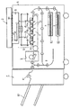
図1は本発明に従うベルト寄り制御機構を適用したベルト方式定着装置を具備させた画像形成装置の一例の概略構成模型図である。図2はこの画像形成装置の画像形成ステイション部分の拡大図である。
(1) Example of Image Forming Apparatus FIG. 1 is a schematic configuration model diagram of an example of an image forming apparatus provided with a belt type fixing device to which a belt shift control mechanism according to the present invention is applied. FIG. 2 is an enlarged view of an image forming station portion of the image forming apparatus.
本例の画像形成装置は、電子写真プロセスを用いた、複数の光走査手段を有する、4ドラムタンデムタイプのレーザービームプリンターである。このプリンター自体は公知に属するからその説明は簡単にとどめる。 The image forming apparatus of this example is a four-drum tandem type laser beam printer having a plurality of optical scanning units using an electrophotographic process. Since this printer itself belongs to the public domain, its description will be kept simple.
このプリンターは、プリンター本体Aの上面側に配設したリーダ部Bでカラー原稿の画像情報をCCD等の光電変換素子で色分解読取り処理する。Cはリーダ部Bの原稿台カラスB1に対する自動原稿給送装置または原稿圧着板である。リーダ部Bでの各色分解読取り画像情報に対応して変調されたレーザ光La,Lb,Lc,Ldを複数の光走査手段を有するレーザ走査部Dから出力させる。 In this printer, image information of a color document is color-separated and read by a photoelectric conversion element such as a CCD by a reader unit B disposed on the upper surface side of the printer body A. C is an automatic document feeder or document pressing plate for the document table crow B1 of the reader unit B. Laser light La, Lb, Lc, Ld modulated corresponding to each color separation read image information in the reader unit B is output from a laser scanning unit D having a plurality of optical scanning means.
図2のように、マゼンタ,シアン,イエロー,ブラックの各色の画像を形成する4つの画像形成ステイションPa,Pb,Pc,Pdの各感光ドラム1a,1b,1c,1dに上記レーザ走査部Dから出力されるレーザ光La,Lb,Lc,Ldで走査露光する工程を含む電子写真プロセスを適用して、上記各色のトナー画像を上記の各画像形成ステイションの感光ドラム上に形成させる。そしてその各画像形成ステイションの感光ドラム上に形成されたマゼンタ,シアン,イエロー,ブラックの各色のトナー画像を転写部3の転写ベルト31上に保持されて搬送される紙等の記録材Pへ順次に重畳転写させる構成となっている。
As shown in FIG. 2, the laser scanning section D is provided on the photosensitive drums 1a, 1b, 1c, and 1d of the four image forming stations Pa, Pb, Pc, and Pd that form images of magenta, cyan, yellow, and black. The toner images of the respective colors are formed on the photosensitive drums of the respective image forming stations by applying an electrophotographic process including a step of scanning exposure with the laser beams La, Lb, Lc, and Ld output from the above. Then, the magenta, cyan, yellow, and black toner images formed on the photosensitive drum of each image forming station are held on the
マゼンタ,シアン,イエロー,ブラックの各色の画像を形成する各画像形成ステイションPa,Pb,Pc,Pdには、それぞれ感光ドラム1a,1b,1c,1dが配置されており、各感光ドラムは矢印方向に回転自在となっている。さらに、各感光ドラム1a,1b,1c,1dの周囲には、帯電器12a,12b,12c,12d、現像装置2a,2b,2c,2d、そして、クリーナ4a,4b,4c,4dが上記感光ドラムの回転方向に沿って順次配設されている。各感光ドラムの下方には、転写部3が配設されている。該転写部3は、各画像形成ステイションに共通の記録材搬送手段たる転写ベルト31及び転写用帯電器3a,3b,3c,3dを有している。転写ベルト31はエンドレスベルトであり、駆動ローラー32とターンローラー33・34の3本のローラー間に懸回張設されている。
Photosensitive drums 1a, 1b, 1c, and 1d are arranged in image forming stations Pa, Pb, Pc, and Pd that form images of magenta, cyan, yellow, and black, respectively. It is freely rotatable in the direction. Further, around the photosensitive drums 1a, 1b, 1c, and 1d, the
E1,E2はプリンター本体A内に配設の第1または第2の給紙カセットである。上記の給紙カセットE1またはE2から記録材供給手段により1枚分離給紙された記録材Pは、転写ベルト31上に支持されて各画像形成ステイションPa,Pb,Pc,Pdへ順次に搬送され、上記各感光ドラム上に形成された各色のトナー画像を順次に重畳転写される。
E1 and E2 are first or second paper feed cassettes disposed in the printer main body A. The recording material P separated and fed by the recording material supply means from the paper feeding cassette E1 or E2 is supported on the
この転写工程が終了すると、記録紙Pは転写ベルト31から分離されて定着装置5へと搬送される。定着装置5で記録紙Pに転写されたトナー像は熱と圧力により記録紙P上に定着され、フルカラー画像形成物として排紙処理装置Fに搬送される。排紙処理装置Fでは記録紙Pを排紙トレイ62上の搬送ローラー61で排出し、排紙トレイは下方に移動することで多数枚の排紙積載が可能となっている。また、排紙処理装置Fでは多数枚の記録紙Pをスティップルしたりする処理も可能である。
When this transfer process is completed, the recording paper P is separated from the
両面コピーモードのときは、定着装置5を出た片面側コピー済みの記録紙Pは反転再搬送機構G側に進路変更され、この反転再搬送機構Gで反転されて転写ベルト31に再給紙されることで、記録紙Pの他方の面側にトナー画像が転写形成され、定着装置5に再び導入されて、両面コピーが排紙処理装置Fに搬送される。
In the double-sided copy mode, the recording paper P that has been copied on one side from the fixing
(2)定着装置5
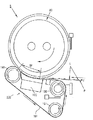
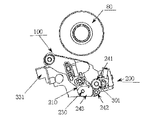
定着装置5は本発明に従うベルト寄り制御機構を適用したベルト方式の定着装置である。図3はその概略構成を示す横断面模型図である。基本的には前述した図16のベルト方式定着装置と同様の構成であり、80は定着ローラー(搬送ローラー)、100は定着ベルトユニット、101はエンドレスの定着ベルト、130はインレットローラー(入り口ローラー)、141は分離ローラー、151はステアリングローラー、160は定着パッド部で、それぞれ、図16のベルト方式定着装置における、定着ローラー510、ベルトユニット53、定着ベルト531、入り口ローラー532、分離ローラー533、ステアリングローラー534、加圧パッド部540に対応している。エンドレスの定着ベルト101は、複数のベルト張架ローラーとしての、インレットローラー130、分離ローラー141、ステアリングローラー151の3本のローラー間に張架させてある。定着動作・制御は図16のベルト方式の定着装置と同様である。即ち、回転可能な定着ローラー80と、定着ローラー80を加熱する加熱手段(520)と、複数のベルト張架ローラー130・141・151の間に張架されて回転するエンドレスのベルト101の外側を定着ローラー80に圧接させて定着ニップ部Wを形成するするベルト機構100と、ベルト機構の1つのベルト張架ローラー151を揺動部材にして他のベルト張架ローラー130・141に対する相対位置を変位させることで、回転時のベルト101のベルト張架ローラー軸線方向への寄り移動を制御するベルト寄り制御機構と、を有し、定着ニップ部Wに未定着トナー像tを担持させた記録材Pを挟持搬送させてトナー像を定着する定着装置である。
(2)
The fixing
特徴点は定着ベルトユニット100におけるベルト寄り制御機構に工夫がある。以下、ベルト寄り制御機構について詳述する。
A characteristic point is that the belt shift control mechanism in the fixing
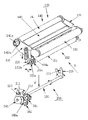
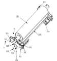
図4と図5はそれぞれ定着ベルトユニット100(定着ベルトは図示せず)の斜視模型図を示している。図4は該ユニット100を前側から見た斜視模型図、図5は奥側から見た斜視模型図である。
4 and 5 are perspective model views of the fixing belt unit 100 (the fixing belt is not shown). FIG. 4 is a perspective model view of the
定着ベルトユニット100の定着パッド部(ベルト101の内側に設けられ定着ローラ80にベルトを圧接する加圧部材)160は前側板110と後側板120に固定されている。この前側板110と後側板120に対しインレットローラー130が回動可能に支持されている。分離ローラー部140は分離ローラー141の両端部141a、141bにベアリング142a、142bが取り付けられていている。ステアリングローラー部150は、図4のように、ステアリングローラー151の前端部151aにベアリング152aが設けられ、それが前加圧アーム153の長穴153aに取り付けられている。ステアリングローラー151はベルト寄り補正ローラー(揺動部材)であり、前加圧アーム153の長穴153aに対して矢印bの方向に移動する。また、前加圧アーム153は加圧バネ154aにより矢印c方向にステアリングローラーを加圧していて、これにより定着ベルト101(図3)にテンションを加えている。
Fixing fixing pad portion of the belt unit 100 (pressing presses the belt with the fixing
同様に後側板120側でも、図5のように、ステアリングローラー151の後端部151bにベアリング152bが設けられ、後加圧アーム155の長穴155aに取り付けられている。ステアリングローラー151はこの後加圧アーム155の長穴155aに対して矢印bの方向に移動する。また、後加圧アーム155は加圧バネ154bにより矢印c方向にステアリングローラー151を加圧していて、これにより定着ベルト101(図3)にテンションを加えている。
Similarly, on the
200はステアリング制御部であり、前ステアリングローラー支持部材(第一の保持部材)210と、後ステアリングローラー支持部材(第二の保持部)220を有し、この前ステアリングローラー支持部材210と後ステアリングローラー支持部材220の回動中心に配置される制御軸230がある。前ステアリングローラー支持部材210は制御軸230の前端部(一端部)に回動可能(回転可能)に支持され、後ステアリングローラー支持部材220は制御軸230の後端部(他端部)に固定(固定支持)されている。また、制御軸230にはステアリング検知フラグ231(図5)が設けられて、対向する検知センサー232により制御軸230の回転方向の位置を検知している。
A
図6は図4の矢印X側から見た図である。図4〜図6において、定着ベルトユニット100を矢印Y方向にステアリング制御部200に装着すると、ステアリングローラー151の前側(一端部側)の受け部151c(図6)は前ステアリングローラー支持部材210のU溝211に装着(保持)され、ステアリングローラー151の後側(他端部側)の受け部151dは後ステアリングローラー支持部材220のU溝221に装着(保持)される。
6 is a view as seen from the arrow X side in FIG. 4 to 6, when the fixing
図7はステアリング制御部200の前端部側を上方から見た図である。前ステアリングローラー支持部材210にはギア(第一の被駆動ギア)212が形成され、入力ギア241と噛み合っている。また、入力ギア241はアイドラーギア242を介してギア(第二の被駆動ギア)243aが形成された制御アーム243に噛合している。制御アーム243は制御軸230の前端部に前ステアリングローラー支持部材210に隣接して固定支持されている。また、アイドラ−ギア242は上下の位置関係でステアリングローラー支持部材210のギア212とは噛合していない。
FIG. 7 is a view of the front end side of the
上記において、入力ギア241が駆動部材である。ギア212が、駆動部材としての入力ギア241の駆動力を第一の保持部材としての前ステアリングローラー支持部材210に伝達して該支持部材210を回転させる第一の駆動伝達系である。またアイドラ−ギア242とギア243aが、駆動部材としての入力ギア241の駆動力を第二の保持部材としての後ステアリングローラー支持部材220に伝達して該支持部材220を回転させる第二の駆動伝達系である。
In the above, the
以上の構成で、入力ギア241が正回転又は逆回転すると、前ステアリングローラー支持部材210は入力ギア241と逆の方向に回転する。また、入力ギア241の回転によりアイドラ−ギア242を介して制御アーム243を入力ギア241と同じ方向に回転させる。制御アーム243は制御軸230に固定され、後ステアリングローラー支持部材220をおなじ方向に回転させる。即ち、入力ギア241の回転によって前ステアリングローラー支持部材210と後ステアリングローラー支持部材220が制御軸230の軸線を中心に互いに逆方向に回転動作する。
With the above configuration, when the
これにより、前ステアリングローラー支持部材210のU溝211に装着されているステアリングローラー151の受部151cと後ステアリングローラー支持部材220のU溝221に装着されているステアリングローラー151の受部151dは互いに逆方向に移動することになる。すなわち、ベルト寄り補正ローラーとしてのステアリングローラー151の前端部側と奥端部側が互いに逆方向に移動されて、該ステアリングローラー151の、他のベルト張架部材であるインレットローラー130・分離ローラー141に対する相対位置が変位される(並行度やねじれが変化する)。これにより、ベルトの寄り方向が交互に変更されてベルト寄り移動が所定の移動領域幅内に納められることになる。
Accordingly, the receiving
本実施例では前ステアリングローラー支持部材210と後ステアリングローラー支持部材220は制御軸230のみで連結されているため、特に従来例のような前ステアリングローラー支持部材210と後ステアリングローラー支持部材220の中央部に支軸を有したり、その支軸を支持する部材等が不要となり装置の小型化を容易に実現できる構成となっている。
In the present embodiment, since the front steering
また、入力ギア241と前ステアリングローラー支持部材210、入力ギア241とアイドラ−ギア242、制御アーム243とのギア列は入力ギア241の回転に対して前ステアリングローラー支持部材210と制御アーム243の回転方向が逆になる構成となっていれば、複数のギアを配置したり、タイミングベルトによる駆動構成でも同様の効果を得ることが出来る。
The gear train of the
図8は定着ベルトユニット100を支持する前パッド加圧板(第一の加圧板)331と後パッド加圧板(第二の加圧板)332を示した図である。定着パッド部160は、前パッド加圧板331の受部331aと後パッド加圧板332の受部332a(図示せず。前パッド加圧板と同形状)により支持される。また、後パッド加圧板332には定着ベルト寄り検知部270が取り付けられている。制御軸230はこの前パッド加圧板331と後パッド加圧板332にその両端がベアリングにより回転自在に保持されている。
FIG. 8 is a view showing a front pad pressure plate (first pressure plate) 331 and a rear pad pressure plate (second pressure plate) 332 that support the fixing
図9は定着ベルトユニット100を前パッド加圧板331、後パッド加圧板332に装着した状態の前パッド加圧板331側を示す図で、前ステアリングローラー支持部材210のU溝211にステアリングローラー151の受部151cが装着されている。制御アーム243には位置決め穴243cが設けられ、同様の穴が前ステアリングローラー支持部材210、前パッド加圧板331にも設けられている。この制御アーム243には位置決め穴243cと、前ステアリングローラー支持部材210の穴(図示せず)と、前パッド加圧板331の穴(図示せず)を一致させることで前パッド加圧板331に対する前ステアリングローラー支持部材210と制御アーム243の位相を合わせることが出来る。また、入力ギア241、アイドラ−ギア242も前パッド加圧板331に取り付けられている。
FIG. 9 is a diagram showing the front
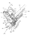
図10は定着ローラー80に定着ベルトユニット100を加圧する加圧機構300を示す図である。加圧機構300は図示していない定着フレームに取り付けられた回動軸301を有していてカム304がカム軸303を中心に回転することで前加圧板311のコロ305を持ち上げることで、加圧機構300を矢印U方向に揺動して定着ローラー80に定着ベルトユニット100が加圧、着脱(選択的に加圧、加圧解除)する構成となっている。定着ベルトユニット100の後側(奥側)も同様の構成である。
FIG. 10 is a diagram showing a
図11は図10の矢印K側から見た図であり、加圧カム304は前加圧板311を持ち上げる。前加圧板311にはパッド加圧バネ312、分離加圧バネ313が設けられている。パッド加圧バネ312は前パッド加圧板331を矢印F方向に持ち上げ、分離加圧バネ313は前分離加圧板321を矢印F方向に持ち上げる。本構成は後パッド加圧板332側も同様の構成からなっている。
FIG. 11 is a view seen from the arrow K side in FIG. 10, and the
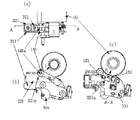
図12の(a)は定着装置5の前端部側を上方から見た図、(b)は正面から見た図、(c)は(a)をA−Aで切断した断面図である。分離ローラー141の端部141aには加圧ベアリング143が取り付けてある。加圧ベアリング143は前分離加圧板321の斜面321aと接触している。奥側も同様の構成であり、これにより分離ローラー141は定着ローラー80に対して前分離加圧板321の斜面321aとは垂直の矢印J方向に加圧される。前パッド加圧板331は溝331aを有し、これにパッドホルダー161が嵌合している。この構成は奥側も同様である。これによりパッド部160は定着ローラー80に対して矢印K方向に加圧している。
12A is a view of the front end side of the fixing
このような加圧機構300により定着ローラー80に対して定着パッド160は加圧されているが、前パッド加圧板331と後パッド加圧板332が各々独立していることで定着パッド160の加圧を前奥各々適正に加圧することが出来る。制御軸230は前パッド加圧板331と後パッド加圧板332にベアリングにより取り付けられていて完全には固定されていないので前パッド加圧板331、後パッド加圧板332の位置を制約することがない。
The
図13は定着ベルトユニット100が定着ローラー80から離間している状態を示している。加圧機構300はカム304がカム軸303を中心に回転することで前加圧板311をV方向に移動させる。これにより定着ベルトユニット100は定着ローラー80から離間することとなる。たとえば、定着装置5でジャムが発生した場合など定着ローラー80と定着ベルトユニット100が離間しているとジャム処理が容易に行える。
FIG. 13 shows a state in which the fixing
図14は上記定着ローラー80から定着ベルトユニット100が離間している状態の前パッド加圧板331の状態を示している(図9とおなじ状態)。前パッド加圧板331には入力ギア241、アイドラ−ギア242、制御アーム243が取り付けられ、前パッド加圧板331、後パッド加圧板332に制御軸230が保持されているので前加圧板311、後加圧板312が回動して前パッド加圧板331、後パッド加圧板332も同様に回動してもステアリング制御部200も同様に回動するので定着ベルトユニット100が定着ローラー80から離間しても同様にステアリングローラー部150の制御を行うことが出来る。ここで、入力ギア241の回転中心は回動軸301と同軸となっている。これにより前パッド加圧板311が回動してもこの入力ギアの位置は移動しない。
FIG. 14 shows a state of the front
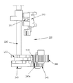
図15はステアリング駆動部400を示している図で、図示していない定着フレームに固定されている。ステアリング駆動モーター(正逆転モーター:回転駆動力を発生する駆動モーター)401には出力ギア402が取り付けられ、減速ギア403a、403b、403c、403d、が軸403e、403fを中心に出力ギア402の駆動を伝達している。中継ギア404aは減速ギア403dと噛み合っていて且つ軸404cに固定されている。中継ギア404bも軸404cに固定されているので中継ギア404aが回転すると中継ギア404bも同様に回転する。中継ギア404bはステアリング制御部200の入力ギア241と噛み合っている。これによりステアリング駆動モーター401が回転すると入力ギア241が回転し前ステアリング支持部材210、後ステアリング支持部材220が各々逆方向に回転する。
FIG. 15 is a view showing the
入力ギア241の回転中心の回動軸301はステアリング駆動部400と同様に定着フレーム(図示せず)に取り付けられているので、加圧機構300により前パッド加圧板331が移動してもステアリング駆動部400の駆動を伝達することが出来る。
Since the
以上の構成でステアリング駆動部400は前側、後側に対しては制御軸230のみが配置されているのみで定着装置の小型化を実現するのに有効な構成となっている。また、入力ギア241を加圧機構300の回動中心に配置したことで駆動系は固定された定着フレームに配置できた。
With the above-described configuration, the
上述した本実施例のベルト方式定着装置は、定着ローラー80が回転駆動され、それに伴い定着ベルト101が従動回転し、該定着ベルト101の回転過程(ベルト101の回転時)で、該定着ベルト101がベルトローラー532・533・534のベルト張架ローラー軸線方向(ローラー長手方向、あるいはベルト移動方向を横切るベルト幅方向)の一方側又は他方側にローラーに沿って寄り移動してその寄りが許容を超えたことがベルト寄り位置検知センサー(不図示)で検知されると、制御部(不図示)は定着ベルト101をその寄り側とは反対方向に戻し移動する方向となるようにステアリング駆動部400のステアリング駆動モーター401を正転または逆転制御することでステアリング制御部200を制御してステアリングローラー151を変位させる。このベルト戻し移動により上記のベルト寄り位置検知センサーがベルトを検知しなくなったらステアリング駆動モーター401の駆動を停止させる。この制御動作の繰り返しにより、ベルトの寄り方向を交互に変更修正してベルト寄り移動を所定の移動領域幅内に納めることができる。
In the belt-type fixing device of the present embodiment described above, the fixing
本実施例では画像形成装置のベルト方式定着装置に関して説明したが、同様の機構を有する転写ベルトや、画像形成装置以外でもベルトを使用する装置においても同様の機構を使用することで本発明と同様の効果を得ることが出来る。 In this embodiment, the belt type fixing device of the image forming apparatus has been described. However, the same mechanism is used in a transfer belt having a similar mechanism, and in a device using a belt other than the image forming apparatus, as in the present invention. The effect of can be obtained.
80:定着ローラー、100:定着ベルトユニット、150:ステアリングローラー部、200:ステアリング駆動部、300:加圧機構 80: fixing roller, 100: fixing belt unit, 150: steering roller unit, 200: steering driving unit, 300: pressure mechanism
Claims (2)
回動可能に支持された制御軸と、
前記制御軸の一端部に、前記制御軸に対して回転可能に支持された、前記揺動部材の一端部側を保持する第一の保持部材であって、第一の被駆動ギアが形成された第一の保持部材と、
前記制御軸の他端部に固定支持された、前記揺動部材の他端部側を保持する第二の保持部材と、
前記制御軸に第一の保持部材と隣接して固定支持された制御アームであって、第二の被駆動ギアが形成された制御アームと、
前記制御アームの前記第二の被駆動ギアと噛合するアイドラーギアと、
前記第一の保持部材の前記第一の被駆動ギア及び前記アイドラーギアと噛合して、回転することにより前記第一の保持部材及び前記制御アームを互いに逆方向に回転させる入力ギアと、
を有し、前記入力ギアの回転によって前記第一と第二の保持部材が前記制御軸の軸線を中心に互いに逆方向に回転動作することにより、前記揺動部材の両端が互いに逆方向に変位することを特徴とするベルト寄り制御機構。 And a plurality of one belt-stretching roller belt mechanism having an endless belt that rotates being stretched between the belt-stretching roller to the swing member by displacing the relative position with respect to the other of the belt-stretching roller, In the belt offset control mechanism that controls the shift of the belt in the axial direction of the belt tension roller during rotation,
A control shaft that is rotatably supported,
A first holding member , which is supported at one end of the control shaft so as to be rotatable with respect to the control shaft and holds one end of the swinging member, is formed with a first driven gear. A first holding member ;
A second holding member that is fixedly supported on the other end of the control shaft and holds the other end of the swing member;
A control arm fixedly supported adjacent to the first holding member on the control shaft, wherein the control arm is formed with a second driven gear ;
An idler gear meshing with the second driven gear of the control arm;
An input gear that meshes with the first driven gear and the idler gear of the first holding member and rotates the first holding member and the control arm in opposite directions by rotating ;
Has a displacement by said first and second holding member by the rotation of the input gear to rotate in the opposite directions about the axis of the control shaft, the ends opposite directions of the swing member A belt shift control mechanism.
前記ベルト寄り制御機構は請求項1に記載のベルト寄り制御機構であり、The belt shift control mechanism is the belt shift control mechanism according to claim 1,
前記ベルトの内側に設けられ、前記定着ローラーにベルトを圧接する加圧部材と、A pressure member that is provided inside the belt and presses the belt against the fixing roller;
前記ベルト寄り制御機構における制御軸の一端部側と他端部側で前記加圧部材を前記定着ローラーに向けて夫々加圧する第一の加圧板と第二の加圧板と、A first pressure plate and a second pressure plate that pressurize the pressure member toward the fixing roller on one end side and the other end side of the control shaft in the belt shift control mechanism,
前記定着ローラーに前記ベルトを選択的に加圧、加圧解除するために、前記第一の加圧板と第二の加圧板を前記ベルト寄り制御機構における入力ギアの回動中心と同軸に回動可能に支持した回動軸と、In order to selectively pressurize and release the belt from the fixing roller, the first pressure plate and the second pressure plate are rotated coaxially with the rotation center of the input gear in the belt shift control mechanism. A pivot shaft supported in a possible manner;
回転駆動力を発生する駆動モーターと、A drive motor that generates rotational drive force;
前記駆動モーターの駆動力を前記ベルト寄り制御機構における入力ギアに伝達する中継ギアと、A relay gear that transmits the driving force of the drive motor to the input gear in the belt shift control mechanism;
を有し、Have
前記ベルト寄り制御機構における制御軸の一端は前記第一の加圧板に回動可能に支持され、他端は前記第二の加圧板に回動可能に支持され、前記ベルト寄り制御機構における入力ギア及びアイドラーギアは前記第一の加圧板に回動可能に支持されていることを特徴とする定着装置。One end of a control shaft in the belt shift control mechanism is rotatably supported by the first pressure plate, and the other end is rotatably supported by the second pressure plate, and an input gear in the belt shift control mechanism. And the idler gear is rotatably supported by the first pressure plate.
Priority Applications (1)
| Application Number | Priority Date | Filing Date | Title |
|---|---|---|---|
| JP2004095869A JP4455116B2 (en) | 2004-03-29 | 2004-03-29 | Belt shift control mechanism and fixing device |
Applications Claiming Priority (1)
| Application Number | Priority Date | Filing Date | Title |
|---|---|---|---|
| JP2004095869A JP4455116B2 (en) | 2004-03-29 | 2004-03-29 | Belt shift control mechanism and fixing device |
Publications (3)
| Publication Number | Publication Date |
|---|---|
| JP2005283844A JP2005283844A (en) | 2005-10-13 |
| JP2005283844A5 JP2005283844A5 (en) | 2007-02-15 |
| JP4455116B2 true JP4455116B2 (en) | 2010-04-21 |
Family
ID=35182308
Family Applications (1)
| Application Number | Title | Priority Date | Filing Date |
|---|---|---|---|
| JP2004095869A Expired - Fee Related JP4455116B2 (en) | 2004-03-29 | 2004-03-29 | Belt shift control mechanism and fixing device |
Country Status (1)
| Country | Link |
|---|---|
| JP (1) | JP4455116B2 (en) |
Families Citing this family (1)
| Publication number | Priority date | Publication date | Assignee | Title |
|---|---|---|---|---|
| JP5999247B1 (en) * | 2015-12-15 | 2016-09-28 | 富士ゼロックス株式会社 | RECORDING MEDIUM CONVEYING DEVICE, FIXING DEVICE, AND IMAGE FORMING DEVICE |
-
2004
- 2004-03-29 JP JP2004095869A patent/JP4455116B2/en not_active Expired - Fee Related
Also Published As
| Publication number | Publication date |
|---|---|
| JP2005283844A (en) | 2005-10-13 |
Similar Documents
| Publication | Publication Date | Title |
|---|---|---|
| JP5645013B2 (en) | Fixing apparatus and image forming apparatus using the same | |
| JP2014052456A5 (en) | ||
| US9507305B2 (en) | Fixing device having nip pressure adjustment and image forming apparatus | |
| JP6376929B2 (en) | Image forming apparatus | |
| JP2009134080A (en) | Fixing device and image forming apparatus | |
| JP2005309316A (en) | Belt fixing device | |
| US10365600B2 (en) | Belt deviation correction device fixing device, image forming apparatus, and belt deviation correction method | |
| JP4455116B2 (en) | Belt shift control mechanism and fixing device | |
| JP6269192B2 (en) | Image forming apparatus | |
| JPS59188673A (en) | Fixing device | |
| JP2012113098A (en) | Drive transmission mechanism, and image heating device and image forming apparatus | |
| JP4627439B2 (en) | Image recording device | |
| JP4764306B2 (en) | Endless belt skew regulating device and image recording device | |
| JP2021131523A (en) | Driving mechanism, fixing device, conveying device, and image forming apparatus | |
| JP2002040863A (en) | Fixing device and image forming device using it | |
| JP2010266827A (en) | Fixing device and image forming apparatus | |
| US8422927B2 (en) | Fixing device and image forming apparatus | |
| JP2007139809A (en) | Image heating device | |
| JP4645829B2 (en) | Fixing apparatus and image forming apparatus | |
| JP5470033B2 (en) | Fixing apparatus and image forming apparatus | |
| JP4564833B2 (en) | Image forming apparatus and sheet conveying apparatus | |
| JP2006349885A (en) | Fixing device and image forming apparatus | |
| JP5371595B2 (en) | Image forming apparatus | |
| JP5174444B2 (en) | Image forming apparatus | |
| KR100824165B1 (en) | Image heating apparatus |
Legal Events
| Date | Code | Title | Description |
|---|---|---|---|
| A521 | Written amendment |
Free format text: JAPANESE INTERMEDIATE CODE: A523 Effective date: 20061221 |
|
| A621 | Written request for application examination |
Free format text: JAPANESE INTERMEDIATE CODE: A621 Effective date: 20061221 |
|
| A977 | Report on retrieval |
Free format text: JAPANESE INTERMEDIATE CODE: A971007 Effective date: 20090811 |
|
| A131 | Notification of reasons for refusal |
Free format text: JAPANESE INTERMEDIATE CODE: A131 Effective date: 20091013 |
|
| A521 | Written amendment |
Free format text: JAPANESE INTERMEDIATE CODE: A523 Effective date: 20091208 |
|
| TRDD | Decision of grant or rejection written | ||
| A01 | Written decision to grant a patent or to grant a registration (utility model) |
Free format text: JAPANESE INTERMEDIATE CODE: A01 Effective date: 20100202 |
|
| A01 | Written decision to grant a patent or to grant a registration (utility model) |
Free format text: JAPANESE INTERMEDIATE CODE: A01 |
|
| A61 | First payment of annual fees (during grant procedure) |
Free format text: JAPANESE INTERMEDIATE CODE: A61 Effective date: 20100203 |
|
| FPAY | Renewal fee payment (event date is renewal date of database) |
Free format text: PAYMENT UNTIL: 20130212 Year of fee payment: 3 |
|
| R150 | Certificate of patent or registration of utility model |
Ref document number: 4455116 Country of ref document: JP Free format text: JAPANESE INTERMEDIATE CODE: R150 Free format text: JAPANESE INTERMEDIATE CODE: R150 |
|
| FPAY | Renewal fee payment (event date is renewal date of database) |
Free format text: PAYMENT UNTIL: 20140212 Year of fee payment: 4 |
|
| RD03 | Notification of appointment of power of attorney |
Free format text: JAPANESE INTERMEDIATE CODE: R3D03 |
|
| LAPS | Cancellation because of no payment of annual fees |