JP4454850B2 - Machine for machining workpieces with saw teeth - Google Patents
Machine for machining workpieces with saw teeth Download PDFInfo
- Publication number
- JP4454850B2 JP4454850B2 JP2000518810A JP2000518810A JP4454850B2 JP 4454850 B2 JP4454850 B2 JP 4454850B2 JP 2000518810 A JP2000518810 A JP 2000518810A JP 2000518810 A JP2000518810 A JP 2000518810A JP 4454850 B2 JP4454850 B2 JP 4454850B2
- Authority
- JP
- Japan
- Prior art keywords
- tool
- pivot
- machine
- tool head
- reciprocating
- Prior art date
- Legal status (The legal status is an assumption and is not a legal conclusion. Google has not performed a legal analysis and makes no representation as to the accuracy of the status listed.)
- Expired - Fee Related
Links
Images


Classifications
-
- B—PERFORMING OPERATIONS; TRANSPORTING
- B23—MACHINE TOOLS; METAL-WORKING NOT OTHERWISE PROVIDED FOR
- B23D—PLANING; SLOTTING; SHEARING; BROACHING; SAWING; FILING; SCRAPING; LIKE OPERATIONS FOR WORKING METAL BY REMOVING MATERIAL, NOT OTHERWISE PROVIDED FOR
- B23D63/00—Dressing the tools of sawing machines or sawing devices for use in cutting any kind of material, e.g. in the manufacture of sawing tools
- B23D63/08—Sharpening the cutting edges of saw teeth
- B23D63/12—Sharpening the cutting edges of saw teeth by grinding
- B23D63/14—Sharpening circular saw blades
Landscapes
- Engineering & Computer Science (AREA)
- Mechanical Engineering (AREA)
- Machine Tool Units (AREA)
- Grinding And Polishing Of Tertiary Curved Surfaces And Surfaces With Complex Shapes (AREA)
- Constituent Portions Of Griding Lathes, Driving, Sensing And Control (AREA)
- Finish Polishing, Edge Sharpening, And Grinding By Specific Grinding Devices (AREA)
Description
【0001】
本発明は、請求項1の前提部分に規定されるような機械に関するものである。
【0002】
この種の公知の機械(DE 27 51 408 A1)においては、基準軸線は、マシンベッド上に配置されて径方向に突出するビームを支持するロッカ支承装置により規定されている。このビームは、往復送り台案内手段を備えて形成されており、往復送り台は、この往復送り台案内手段に沿って基準軸線に関して径方向に変位可能である。往復送り台上に設けられたピボット軸受手段は、往復送り台案内手段と平行に延びると共に基準軸線と直角に交叉するピボット軸線を規定している。スピンドルヘッドが固定されている軸は、ピボット軸受手段内に支持されている。スピンドルスリーブは、スピンドルヘッドの内部で、ピボット軸線と直角に交叉する研削スピンドル軸線に沿って送り駆動装置によって変位されるように案内される。このように供給送り台に相当するスピンドルスリーブは、回転駆動されるようになっていると共に、丸鋸刃を研ぐためプレート形状の研削ディスクを支持する研削スピンドルを含んでいる。歯の前面にある真直ぐな面(すくい面)又は歯の裏側にある真直ぐな面(クリアランス面)を鋭利にすべきときには、スピンドルスリーブは、常に、研削ディスクの作用前面が基準軸線を含む平面にあるような方法で、送り駆動装置により調節される。斜めの面を研削するために、スピンドルヘッドは、傾斜の方向に応じて、一方の方向或いは他方の方向にピボット軸線回りに揺動される。これを実行するため、スピンドルヘッドから離れたところにあるスピンドルヘッド支持軸の端部に横棒が取り付けられ、そして2本のロールが、ピボット軸線から等距離のところで該ピボット軸線に関して径方向に対峙して該横棒上で自由に回転可能であるように支持されている。これら2本のロールは、それぞれ、各ピストン・シリンダユニット及び各可調節ストッパの間に、横棒と、該横棒に加えて、横棒及びスピンドルヘッドの双方を支持する軸とが、各ストッパにより制限される揺動範囲内で前後に揺動もしくは枢回可能な態様で、配置されている。従って、スピンドルスリーブ及びその送り駆動装置が揺動運動に加わるので、移動させるべき慣性質量は実際に相当に大きくなる。その結果、前後方向の揺動運動で達成される枢回度数が制限される。
【0003】
本発明の目的は、鋸歯を有する加工物を機械加工するための機械を、同機械が交互する方向に斜めになっている即ち面取りされている歯の前面又は背面の表面を機械加工するときに、上述した既知機械よりも迅速に作動できるように改良することである。
【0004】
この目的は、請求項1に規定された特徴により本発明に従って達成される。好適な更なる開発の結果は従属請求項の内容になっている。
【0005】
どんな(機械的)ストッパも当接物も同時に必要なしにステップモータによって行われる本発明による枢回駆動は、特に、工具ヘッドの迅速な往復枢回運動と、共同の揺動運動のため該工具ヘッドに接続された全ての構造要素の迅速な往復枢回運動とを可能にする。それにもかかわらず、この枢回駆動は、マシンベッドから工具までずっと延びる運動連鎖に何らの不快な振動を生じさせることがない。枢回すべき部材群の可能な最も迅速な加速に加えて、所望の傾斜に近づくときにそれらのスムーズな減速を達成するのに適するものなら、どんな慣用のステップモータでも使用しうる。請求項3に記載したような段階的減速もしくは逓減伝動装置は、振動なしに枢回運動を行うことを更に確実にする。
【0006】
以下に、本発明の実施例を概略的図面に関して詳細に説明する。
【0007】
図解した機械で加工されるべき加工物10の図示の例は、硬質金属仕上げの鋸歯12を有する丸鋸刃であり、各鋸歯は、その歯先18を機械の固定基準軸線A上の所定位置に保持しながらその歯面14及び背面16を機械加工されるべきである。
【0008】
図示の機械は、マシンベッド20を備えると共に、その上にある、固定型水平供給送り台案内手段22を備え、供給送り台24は、この水平供給送り台案内手段22に沿って、送りスピンドル28によって変位されるように、特にサーボモータ或いはステップモータのような数値制御の電気モータ26により案内される。供給送り台24の各位置は、距離測定手段30により監視される。
【0009】
供給送り台24のところには垂直往復送り台案内手段32が配置されていて、往復送り台34は、距離測定手段40による監視を受けながら、昇降スピンドル38を介して、特にサーボモータ或いはステップモータのような数値制御される電気モータ36によって上述の案内手段に沿って上下に可動である。往復送り台34は、往復送り台案内手段32と平行なピボット軸線B、即ち図示の実施例においては垂直なピボット軸線を規定する内蔵ピボット軸受手段42を有している。このピボット軸線Bは、ピボット軸受手段42内に支持されるピボット軸44の軸心であり、このピボット軸44がその下端に取り付けられた工具ヘッド46を支持する。
【0010】
軸受箱50は、絶縁スリーブ48により電気的に絶縁された態様で工具ヘッド46内に取り付けられると共に、スピンドル軸線Cを規定している。このスピンドル軸線Cは、図示の実施例においては水平であり、ピボット軸線Bに対して直角に交叉する。これは、軸受箱50内に支持されてモータ56にベルト駆動手段54で接続された工具スピンドル52の軸線である。このモータ56は、周波数変換器により給電される電気モータとして具現されているので、工具スピンドル52は、広い範囲内で可変の回転速度で駆動することができる。
【0011】
往復送り台34は上側突出アーム58を有し、工具ヘッド46を枢回させるためこの上側突出アーム58に枢回駆動手段60が設けられている。枢回駆動手段60は、特にサーボモータ又はステップモータである数値制御モータ62と、段階的減速伝動装置64とを備えており、段階的減速伝動装置64は、モータ62の軸と突出アーム58により支持された中間ベルト車68を相互に接続する第1の歯付きベルト66と、該中間ベルト車68にしっかり接続されると共に、ピボット軸44に固定されたベルト車74に第2の歯付きベルト72によって連結される中間小ベルト車70とを有する。
【0012】
枢回駆動手段60は、真直ぐな歯面14又は真直ぐな背面16を研削すべきときに、スピンドル軸線Cが基準軸線Aに対して垂直に延びている図1乃至図5に示す通常位置に工具ヘッド46があるように、数値制御で調節される。工具ヘッド46は、斜めの歯面14或いは斜めの背面16を有する鋸歯12を研磨するために、又は鋸歯12の横フランクと背面16との間の縁部を面取りするために、枢回駆動手段60によって数値制御下に、その通常位置からどちらかの側へ向かう傾斜位置へと揺動することができる。
【0013】
加工物送り台案内手段76は、基準軸線Aの回りに枢回運動可能にマシンベッド20上に支持され、そして鋸歯12の背面16(図4)或いは歯面14(図6)のどちらを機械加工すべきかに応じて、該鋸歯12のクリアランス角もしくは削り角に対応する位置に設定することができる。加工物送り台案内手段76は、図示の実施例においては手動で作動される調節装置80によって調節可能の加工物送り台78を案内し、該加工物送り台78は加工物10のための加工物支持体82を含んでいる。加工物10は図示の実施例においては丸鋸刃であるから、加工物支持体82は通常のようにぺグを備えており、加工物10は、段階的な態様で前進されるべく加工物の回転軸線Dの回りに回転可能であり、各段階の後、機械加工位置に到達し、そこに、鋸歯12の1つの歯先18が基準軸線A上で位置決めされるように、ペグに装着されている。
【0014】
このような前進移動を行うために前進手段84が設けられている。この前進手段は、基準軸線Aに平行な支承軸線Eの回りに枢回可能なようにマシンベッド上に支持されると共に、前進送り台案内手段86を備えている。該前進送り台案内手段86は基準軸線Aに対して直角に配置されていて、前進送り台88は、この前進送り台案内手段86に沿って往復運動可能に案内される。前進送り台88は、各鋸歯12を機械加工のための位置に押し入れるため対応する歯面14と係合可能に前進フィンガ90を支持する。この前進送り台88はカム従動子92を支持しており、該カム従動子92により、前進送り台は、枢回可能に調節しうる態様でマシンベッド20に装着された偏心部材94のカム面に乗る。この構造の詳細は、1997年10月20日の特許出願第197 46 232号から得るべきである。
【0015】
各増分運動後に加工物10をクランプするため、通常の設計によるクランプ装置96が設けられている。
【0016】
供給送り台24のためのモータ26及び距離測定手段30、往復送り台34のためのモータ36及び距離測定手段40、並びにピボット軸線B回りに工具ヘッド46を枢回調節するためのモータ62及び角度測定手段(図示せず)は数値制御手段98に接続されている。
【0017】
例示した機械の工具スピンドル52に取り付けるべき工具100の例は、鋸歯12の背面16(図1、図4及び図5)を研磨もしくは研削するためのカップ形状の研削ディスクか、鋸歯12の歯面14(図6)を研磨もしくは研削するためのプレート形状の研削ディスクである。なお、図1、図4(及び図5)では、鋸歯12のクリアランス角に対応する位置に工具100が設定されているのに対して、図6では、鋸歯12の削り角に対応する位置に工具100が設定されるように、加工物10が、加工物送り台案内手段76により基準軸線Aを中心に枢回されている。どちらの例においても、工具100は、鋼製の基板102と、この基板に固着される研削層104とを備え、その自由な前面が工具100の作用面となるが、図6では、プレート形状の工具100が、その作用面106を工具スピンドル52の基端側に向けて取付けられている。研削層104は導電性材料を含んでいる。このように全体として導電性である工具100は、該工具100と鋸歯12が互いに接触するときに、該工具100と機械加工すべき各鋸歯とを介して閉じられる電気回路を含む図6に示した測定手段108の一部を形成する。
【0018】
鋸歯12の機械加工位置は、調節装置80による或いはDE 196 30 057 C1に従ったプログラム制御の検知と調節による加工物10の手動調節の結果として識別できる。従って、機械加工すべき鋸歯12の歯先18は基準軸線A上に位置すると考えうる。その後、数値制御手段98は、工具100の作用面106の位置が摩耗の過程で変化するにつれて該位置を求めるために、往復送り台34に幾つかの作動ストロークを行わせる。この作動ストローク中、工具100の作用面106は加工物10の背面16(図4)或いは歯面14(図6)から安全な間隔のところに先ずあり、一方、供給送り台24は、工具100がその作用面106で背面16又は歯面14に接触し、それにより測定手段108の電気回路が閉じるまで、ゆっくり前進される。このような状態が起きる供給送り台24の位置は、距離測定手段30により求められる。該距離測定手段30の任意の所望ゼロ点に関するピボット軸線Bの位置は、最初から分かっている。従って、数値制御手段98は、ピボット軸線Bと工具作用面106との間のその瞬間摩耗状態における距離Xを計算することができる。
【0019】
機械加工すべき面が真直ぐな歯面14、即ち基準軸線Aに平行な歯面であれば、又は真直ぐな背面16であれば、工具100が歯面14又は背面16から除去すべき量に釣り合う量だけ通常の態様で供給送り台24により前方へ移動されるという点は別として、更なる演算操作の必要はない。
【0020】
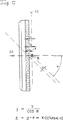
しかし、歯面14又は背面16が斜めであり、加工物軸線Dに関して角度αで傾斜している場合、工具ヘッド46を対応してピボット軸線B回りに揺動させることでは十分でない。付加的に必要なことは、測定した距離Xに適応した供給送り台24の切込みZと工具ヘッドの角度αの傾斜である。この切込みZは、次の式
z=y−x=x(1/cosα−1)
を利用する図5に例示した幾何学的関係に従って数値制御手段98により演算される。切込みZは、図4及び図6に例示したように、距離Xが正であるとき、負の量である。
【0021】
距離Xの大きさは、工具100の摩耗が増すにつれて次第に減少する。しかしながら、図6に示す工具100の場合、ピボット軸線Bが基板102を通って延びているので、距離Xは、研削層104が完全に摩耗するまで、正の値に留まっている。この状況は、研削層104が新しいときピボット軸線Bが基板102と作用面106との間を延びる図4及び図5に示す工具100とは異なっている。その結果、距離Xは図4に従って研削層104の摩耗が増すに連れてゼロまで減少するようになり、そして摩耗が更に進むと、距離Xの値は負になり、斜めの背面16を機械加工するために正の切込みを必要とする。
【0022】
負の切込みは、背面16が既に研削された鋸歯12に面取り部を与える、即ち背面16から横方向の側面のどちらかへの移行部において限られた幅のべべル研削を受けるときにも、必要になる。
【図面の簡単な説明】
【図1】 丸鋸刃を研ぐための機械の正面図である。
【図2】 図1の矢印IIから見た図である。
【図3】 図2の矢印IIIから見た頂部の平面図である。
【図4】 図2の線IV−IVによる断面図である。
【図5】 図4の工具付近の部分拡大図である。
【図6】 図4の変形例を示す断面図である。[0001]
The invention relates to a machine as defined in the preamble of claim 1.
[0002]
In this kind of known machine (DE 27 51 408 A1), the reference axis is defined by a rocker bearing device which is arranged on a machine bed and supports a radially projecting beam. The beam is formed with reciprocating feed guide means, and the reciprocating feed stand is displaceable in the radial direction with respect to the reference axis along the reciprocating feed guide means. The pivot bearing means provided on the reciprocating feed base defines a pivot axis that extends parallel to the reciprocating feed guide means and intersects the reference axis at a right angle. The shaft on which the spindle head is fixed is supported in pivot bearing means. The spindle sleeve is guided within the spindle head to be displaced by a feed drive along a grinding spindle axis that intersects the pivot axis at right angles. Thus, the spindle sleeve corresponding to the supply feed base is rotationally driven, and includes a grinding spindle for supporting a plate-shaped grinding disk for sharpening a circular saw blade. When the straight surface on the front of the tooth (rake surface) or the straight surface on the back of the tooth (clearance surface) should be sharpened, the spindle sleeve will always be in a plane where the working front of the grinding disk contains the reference axis. It is adjusted by the feed drive in some way. In order to grind the slanted surface, the spindle head is swung around the pivot axis in one direction or the other depending on the direction of inclination. To accomplish this, a horizontal bar is attached to the end of the spindle head support shaft remote from the spindle head, and the two rolls are opposed radially to the pivot axis at an equal distance from the pivot axis. Thus, it is supported so as to be freely rotatable on the horizontal bar. Each of these two rolls has a horizontal bar between each piston / cylinder unit and each adjustable stopper, and a shaft that supports both the horizontal bar and the spindle head in addition to the horizontal bar. It is arranged in such a manner that it can be swung back and forth or pivoted within a rocking range limited by. Therefore, since the spindle sleeve and its feed driving device participate in the swinging motion, the inertial mass to be moved is actually considerably large. As a result, the degree of pivoting achieved by the anteroposterior swing motion is limited.
[0003]
It is an object of the present invention to machine a machine for machining a workpiece having saw teeth when machining the front or back surface of a tooth that is beveled or chamfered in alternating directions. It is an improvement to be able to operate faster than the known machines mentioned above.
[0004]
This object is achieved according to the invention by the features defined in claim 1. The result of suitable further development is the content of the dependent claims.
[0005]
The pivoting drive according to the invention, which is carried out by a step motor without the need for any (mechanical) stoppers or abutments at the same time, is particularly suitable for the quick reciprocating pivoting movement of the tool head and the joint swinging movement of the tool. Allows rapid reciprocal pivoting of all structural elements connected to the head. Nevertheless, this pivoting drive does not cause any unpleasant vibration in the motion chain that extends all the way from the machine bed to the tool. In addition to the fastest possible acceleration of the members to be pivoted, any conventional stepper motor can be used that is suitable to achieve their smooth deceleration as it approaches the desired tilt. A step-down deceleration or reduction gearing as claimed in
[0006]
In the following, embodiments of the invention will be described in detail with reference to the schematic drawings.
[0007]
Examples of the illustrated
[0008]
The machine shown includes a
[0009]
A vertical
[0010]
The
[0011]
The reciprocating
[0012]
The pivoting drive means 60 is in the normal position shown in FIGS. 1 to 5 where the spindle axis C extends perpendicularly to the reference axis A when the
[0013]
A
[0014]
Advancement means 84 is provided to perform such forward movement. The advance means is supported on the machine bed so as to be pivotable about a support axis E parallel to the reference axis A, and is provided with an advance feed guide means 86. The forward feed base guiding means 86 is disposed at a right angle to the reference axis A, and the forward feed base 88 is guided along the forward feed base guiding means 86 so as to be reciprocally movable. The advance feed base 88 supports the
[0015]
In order to clamp the
[0016]
[0017]
Examples of the
[0018]
The machining position of the
[0019]
If the surface to be machined is a
[0020]
However, if the
Is calculated by the numerical control means 98 according to the geometrical relationship illustrated in FIG. The cut Z is a negative amount when the distance X is positive, as illustrated in FIGS. 4 and 6.
[0021]
The magnitude of the distance X gradually decreases as the wear of the
[0022]
The negative notch also provides a chamfer on the
[Brief description of the drawings]
1 is a front view of a machine for sharpening circular saw blade.
FIG. 2 is a view seen from an arrow II in FIG.
3 is a plan view of the top as seen from the arrow III in FIG. 2;
4 is a cross-sectional view taken along line IV-IV in FIG.
FIG. 5 is a partially enlarged view of the vicinity of the tool in FIG. 4;
6 is a cross-sectional view showing a modification of FIG.
Claims (5)
マシンベッド(20)と、機械加工すべき鋸歯(12)の歯先(18)が上記マシンベッド(20)に対して固定された基準軸線(A)上にあるように加工物(10)を支持可能な加工物支持体(82)と、ディスク形状の工具(100)を装備できるように適応した工具スピンドル(52)がスピンドル軸線(C)回りに回転駆動されるように支持されている工具ヘッド(46)と、上記マシンベッド(20)上に上記工具ヘッド(46)を可動に支持するためのアセンブリとを備え、
該アセンブリは、
往復送り台案内手段(32)に沿って上記基準軸線(A)を横切る方向に往復動可能な往復送り台(34)と、
供給送り台案内手段(22)に沿って上記往復送り台案内手段(32)を横切る方向に進退可能な供給送り台(24)と、
上記往復送り台案内手段(32)に平行なピボット軸線(B)を規定するピボット軸受手段(42)であって、上記工具ヘッド(46)が、枢回駆動手段(60)により、上記基準軸線(A)に平行に延びる上記鋸歯(12)の表面を上記工具(100)の作用面(106)によって機械加工するための通常位置から、上記鋸歯(12)の傾斜面を上記工具(100)の同じ作用面(106)によって機械加工すべきするための傾斜位置へと、前記ピボット軸線(B)の回りに枢回可能であるピボット軸受手段(42)と、を備えた機械において、
上記枢回駆動手段(60)は数値制御されるモータ(62)を備え、上記工具ヘッド(46)の上記傾斜位置はストッパ手段なしに上記枢回駆動手段によって専ら決定されることを特徴とする、機械。 A machine for machining a workpiece (10) having a saw blade (12),
The workpiece (10) is placed so that the machine bed (20) and the tooth tip (18) of the saw blade (12) to be machined are on a reference axis (A) fixed to the machine bed (20). A tool supported by a support spindle (52) and a tool spindle (52) adapted to be equipped with a disc-shaped tool (100) so that it can be driven to rotate about the spindle axis (C). A head (46) and an assembly for movably supporting the tool head (46) on the machine bed (20);
The assembly is
A reciprocating feed stand (34) capable of reciprocating in a direction crossing the reference axis (A) along the reciprocating feed guide means (32);
A supply feed base (24) capable of moving back and forth in a direction crossing the reciprocating feed guide guide means (32) along the supply feed guide means (22);
Pivot bearing means (42) for defining a pivot axis (B) parallel to the reciprocating feed guide means (32), wherein the tool head (46) is moved by the pivot drive means (60) to the reference axis. From the normal position for machining the surface of the saw blade (12) extending parallel to (A) by the working surface (106) of the tool (100), the inclined surface of the saw blade (12) is moved to the tool (100). between the inclined position to be machined by the same working surface (106), a pivot bearing means (42) said about a pivot axis (B) can be pivotal in the machine with a,
The pivot driving means (60) includes a numerically controlled motor (62), and the tilt position of the tool head (46) is determined solely by the pivot driving means without a stopper means. ,machine.
Applications Claiming Priority (3)
| Application Number | Priority Date | Filing Date | Title |
|---|---|---|---|
| DE19748674.6 | 1997-11-04 | ||
| DE19748674A DE19748674A1 (en) | 1997-11-04 | 1997-11-04 | Machine for machining workpieces with cutting teeth, especially saw blades |
| PCT/EP1998/006918 WO1999022899A1 (en) | 1997-11-04 | 1998-11-02 | Machine for machining work pieces with cutting teeth, especially saw blades |
Publications (3)
| Publication Number | Publication Date |
|---|---|
| JP2001521826A JP2001521826A (en) | 2001-11-13 |
| JP2001521826A5 JP2001521826A5 (en) | 2006-01-05 |
| JP4454850B2 true JP4454850B2 (en) | 2010-04-21 |
Family
ID=7847568
Family Applications (1)
| Application Number | Title | Priority Date | Filing Date |
|---|---|---|---|
| JP2000518810A Expired - Fee Related JP4454850B2 (en) | 1997-11-04 | 1998-11-02 | Machine for machining workpieces with saw teeth |
Country Status (5)
| Country | Link |
|---|---|
| US (1) | US6279424B1 (en) |
| EP (1) | EP1028827B1 (en) |
| JP (1) | JP4454850B2 (en) |
| DE (2) | DE19748674A1 (en) |
| WO (1) | WO1999022899A1 (en) |
Families Citing this family (1)
| Publication number | Priority date | Publication date | Assignee | Title |
|---|---|---|---|---|
| DE112012005443T9 (en) | 2011-12-23 | 2015-01-15 | Williams And White Machine Inc. | Computer-controlled grinding machine with several axes for grinding saw blades |
Family Cites Families (7)
| Publication number | Priority date | Publication date | Assignee | Title |
|---|---|---|---|---|
| DE2614419B2 (en) * | 1976-04-02 | 1979-02-01 | Vollmer Werke Maschinenfabrik Gmbh, 7950 Biberach | Saw sharpening machine |
| DE2751408A1 (en) * | 1977-11-17 | 1979-05-23 | Vollmer Werke Maschf | Circular saw teeth sharpening grinder - has grinding spindle head mounted on shaft for movement between two positions displaced by 180 degrees |
| DE3120465C2 (en) * | 1981-05-22 | 1983-02-17 | Vollmer Werke Maschinenfabrik Gmbh, 7950 Biberach | Saw sharpening machine |
| BR8207909A (en) | 1981-10-05 | 1983-09-13 | Lach Spezial Werkzeuge Gmbh | PROCESS AND DEVICE FOR THE MACHINING OF NON-METALLICALLY CONNECTED MATERIALS |
| JPS59227314A (en) * | 1983-06-05 | 1984-12-20 | Minoru Ando | Grinder for circular saw |
| GB9109832D0 (en) * | 1991-05-07 | 1991-06-26 | Ellis Glynn A | Saw blade machining system |
| DE4242906C2 (en) * | 1992-12-18 | 1995-09-14 | Walter Ag | Numerically controlled grinding machine for grinding preferably metallic workpieces, especially tools |
-
1997
- 1997-11-04 DE DE19748674A patent/DE19748674A1/en not_active Ceased
-
1998
- 1998-11-02 US US09/509,726 patent/US6279424B1/en not_active Expired - Lifetime
- 1998-11-02 JP JP2000518810A patent/JP4454850B2/en not_active Expired - Fee Related
- 1998-11-02 DE DE59803146T patent/DE59803146D1/en not_active Expired - Lifetime
- 1998-11-02 WO PCT/EP1998/006918 patent/WO1999022899A1/en active IP Right Grant
- 1998-11-02 EP EP98954474A patent/EP1028827B1/en not_active Expired - Lifetime
Also Published As
| Publication number | Publication date |
|---|---|
| DE19748674A1 (en) | 1999-05-06 |
| JP2001521826A (en) | 2001-11-13 |
| EP1028827B1 (en) | 2002-02-20 |
| WO1999022899A1 (en) | 1999-05-14 |
| US6279424B1 (en) | 2001-08-28 |
| EP1028827A1 (en) | 2000-08-23 |
| DE59803146D1 (en) | 2002-03-28 |
Similar Documents
| Publication | Publication Date | Title |
|---|---|---|
| JP7372057B2 (en) | Saw machine for miter cutting | |
| JP4443039B2 (en) | Machine for machining workpieces with saw teeth | |
| WO1995035186A1 (en) | Apparatus and method for grinding turbine blades | |
| JPS5927284B2 (en) | Casting deburring machine | |
| JP4027856B2 (en) | Machine Tools | |
| JP4018150B2 (en) | Processing machine for workpieces with cutting teeth | |
| US6329624B1 (en) | Measuring device on a machine for machining workpieces with cutting teeth, especially saw blades | |
| JPH053361B2 (en) | ||
| JP4454850B2 (en) | Machine for machining workpieces with saw teeth | |
| JP2001518395A (en) | A processing machine for processing workpieces with cutting teeth, especially saw blades | |
| JP2004524985A (en) | Grinding machine and method for grinding both sides of a circular saw blade tooth surface | |
| US4524544A (en) | Machine for backing-off and/or grinding drifting spindles provided with teeth | |
| KR101846134B1 (en) | A saw blade grinding machine capable of various machining | |
| US5038639A (en) | Saw blade top and face grinder | |
| JPH08323524A (en) | Chamfering device | |
| JP3698254B2 (en) | Dicing machine | |
| JP3764368B2 (en) | Workrest device and control method thereof | |
| CA1041767A (en) | Grinding machine for carbide cutting elements | |
| KR102005336B1 (en) | Apparatus for grinding sawing blades of bandsaw | |
| CN110769977B (en) | Grinding machine | |
| JPH05285808A (en) | Grinding wheel oscillation in internal grinding and internal grinding machine | |
| JP4014833B2 (en) | Deburring device and deburring method | |
| JPS5919628A (en) | Rough cutting machine | |
| JP2859701B2 (en) | Chip removal equipment for sawing machines | |
| JPH08118213A (en) | Internal cylindrical grinding machine and grinding method |
Legal Events
| Date | Code | Title | Description |
|---|---|---|---|
| A521 | Written amendment |
Free format text: JAPANESE INTERMEDIATE CODE: A523 Effective date: 20051024 |
|
| A621 | Written request for application examination |
Free format text: JAPANESE INTERMEDIATE CODE: A621 Effective date: 20051024 |
|
| A131 | Notification of reasons for refusal |
Free format text: JAPANESE INTERMEDIATE CODE: A131 Effective date: 20080926 |
|
| A601 | Written request for extension of time |
Free format text: JAPANESE INTERMEDIATE CODE: A601 Effective date: 20081224 |
|
| A602 | Written permission of extension of time |
Free format text: JAPANESE INTERMEDIATE CODE: A602 Effective date: 20090107 |
|
| A521 | Written amendment |
Free format text: JAPANESE INTERMEDIATE CODE: A523 Effective date: 20090126 |
|
| A131 | Notification of reasons for refusal |
Free format text: JAPANESE INTERMEDIATE CODE: A131 Effective date: 20090821 |
|
| A521 | Written amendment |
Free format text: JAPANESE INTERMEDIATE CODE: A523 Effective date: 20091118 |
|
| TRDD | Decision of grant or rejection written | ||
| A01 | Written decision to grant a patent or to grant a registration (utility model) |
Free format text: JAPANESE INTERMEDIATE CODE: A01 Effective date: 20100112 |
|
| A01 | Written decision to grant a patent or to grant a registration (utility model) |
Free format text: JAPANESE INTERMEDIATE CODE: A01 |
|
| A61 | First payment of annual fees (during grant procedure) |
Free format text: JAPANESE INTERMEDIATE CODE: A61 Effective date: 20100203 |
|
| FPAY | Renewal fee payment (event date is renewal date of database) |
Free format text: PAYMENT UNTIL: 20130212 Year of fee payment: 3 |
|
| R150 | Certificate of patent or registration of utility model |
Free format text: JAPANESE INTERMEDIATE CODE: R150 |
|
| FPAY | Renewal fee payment (event date is renewal date of database) |
Free format text: PAYMENT UNTIL: 20140212 Year of fee payment: 4 |
|
| R250 | Receipt of annual fees |
Free format text: JAPANESE INTERMEDIATE CODE: R250 |
|
| R250 | Receipt of annual fees |
Free format text: JAPANESE INTERMEDIATE CODE: R250 |
|
| R250 | Receipt of annual fees |
Free format text: JAPANESE INTERMEDIATE CODE: R250 |
|
| R250 | Receipt of annual fees |
Free format text: JAPANESE INTERMEDIATE CODE: R250 |
|
| LAPS | Cancellation because of no payment of annual fees |