JP4454635B2 - BAND ALLOCATION METHOD, BAND ALLOCATION PROGRAM, AND PROGRAM RECORDING MEDIUM - Google Patents
BAND ALLOCATION METHOD, BAND ALLOCATION PROGRAM, AND PROGRAM RECORDING MEDIUM Download PDFInfo
- Publication number
- JP4454635B2 JP4454635B2 JP2006547892A JP2006547892A JP4454635B2 JP 4454635 B2 JP4454635 B2 JP 4454635B2 JP 2006547892 A JP2006547892 A JP 2006547892A JP 2006547892 A JP2006547892 A JP 2006547892A JP 4454635 B2 JP4454635 B2 JP 4454635B2
- Authority
- JP
- Japan
- Prior art keywords
- bandwidth
- flow
- communication
- allocated
- information
- Prior art date
- Legal status (The legal status is an assumption and is not a legal conclusion. Google has not performed a legal analysis and makes no representation as to the accuracy of the status listed.)
- Expired - Fee Related
Links
Images


Classifications
-
- H—ELECTRICITY
- H04—ELECTRIC COMMUNICATION TECHNIQUE
- H04L—TRANSMISSION OF DIGITAL INFORMATION, e.g. TELEGRAPHIC COMMUNICATION
- H04L47/00—Traffic control in data switching networks
- H04L47/10—Flow control; Congestion control
- H04L47/15—Flow control; Congestion control in relation to multipoint traffic
-
- H—ELECTRICITY
- H04—ELECTRIC COMMUNICATION TECHNIQUE
- H04L—TRANSMISSION OF DIGITAL INFORMATION, e.g. TELEGRAPHIC COMMUNICATION
- H04L47/00—Traffic control in data switching networks
- H04L47/10—Flow control; Congestion control
- H04L47/24—Traffic characterised by specific attributes, e.g. priority or QoS
- H04L47/2416—Real-time traffic
-
- H—ELECTRICITY
- H04—ELECTRIC COMMUNICATION TECHNIQUE
- H04L—TRANSMISSION OF DIGITAL INFORMATION, e.g. TELEGRAPHIC COMMUNICATION
- H04L47/00—Traffic control in data switching networks
- H04L47/70—Admission control; Resource allocation
-
- H—ELECTRICITY
- H04—ELECTRIC COMMUNICATION TECHNIQUE
- H04L—TRANSMISSION OF DIGITAL INFORMATION, e.g. TELEGRAPHIC COMMUNICATION
- H04L47/00—Traffic control in data switching networks
- H04L47/70—Admission control; Resource allocation
- H04L47/74—Admission control; Resource allocation measures in reaction to resource unavailability
- H04L47/745—Reaction in network
-
- H—ELECTRICITY
- H04—ELECTRIC COMMUNICATION TECHNIQUE
- H04L—TRANSMISSION OF DIGITAL INFORMATION, e.g. TELEGRAPHIC COMMUNICATION
- H04L47/00—Traffic control in data switching networks
- H04L47/70—Admission control; Resource allocation
- H04L47/80—Actions related to the user profile or the type of traffic
- H04L47/801—Real time traffic
-
- H—ELECTRICITY
- H04—ELECTRIC COMMUNICATION TECHNIQUE
- H04L—TRANSMISSION OF DIGITAL INFORMATION, e.g. TELEGRAPHIC COMMUNICATION
- H04L65/00—Network arrangements, protocols or services for supporting real-time applications in data packet communication
- H04L65/60—Network streaming of media packets
- H04L65/75—Media network packet handling
- H04L65/752—Media network packet handling adapting media to network capabilities
-
- H—ELECTRICITY
- H04—ELECTRIC COMMUNICATION TECHNIQUE
- H04L—TRANSMISSION OF DIGITAL INFORMATION, e.g. TELEGRAPHIC COMMUNICATION
- H04L65/00—Network arrangements, protocols or services for supporting real-time applications in data packet communication
- H04L65/80—Responding to QoS
Landscapes
- Engineering & Computer Science (AREA)
- Computer Networks & Wireless Communication (AREA)
- Signal Processing (AREA)
- Multimedia (AREA)
- Data Exchanges In Wide-Area Networks (AREA)
- Telephonic Communication Services (AREA)
Description
本発明は、帯域割り当て方法、帯域割り当て装置、通信端末、帯域割り当てプログラム及びプログラム記録媒体に関し、特に、使用要求する帯域幅として複数の帯域幅を有するデータストリーミングの送受信を扱うアプリケーションに最適な帯域を割り当てるシステムに対して好適に適用可能である。 The present invention relates to a bandwidth allocation method, a bandwidth allocation device, a communication terminal, a bandwidth allocation program, and a program recording medium, and in particular, an optimum bandwidth for an application that handles transmission / reception of data streaming having a plurality of bandwidths as a requested bandwidth. The present invention can be suitably applied to the system to be assigned.
近年、VoIPやIPテレビ電話・TV会議システム、インターネットラジオ、動画配信などリアルタイムデータストリーミングを扱うアプリケーションの利用が増えてきている。現在これらのアプリケーションは、ADSL(Asymmetric Digital Subscriber Line)などのブロードバンドを用いた固定ネットワーク環境で使用されることが多く、実装するアプリケーションもこのようなブロードバンド環境を想定して実装されている。 In recent years, the use of applications that handle real-time data streaming such as VoIP, IP videophone / TV conference system, Internet radio, and video distribution has been increasing. Currently, these applications are often used in a fixed network environment using broadband such as ADSL (Asymmetric Digital Subscriber Line), and applications to be implemented are also implemented assuming such a broadband environment.
また、このようなストリーミングデータを扱うアプリケーションは、非コネクションプロトコルであるUDP(User Datagram Protocol)を用いることが多い。ここで、UDPは、リアルタイム性に優れている反面、パケットロス等の通信劣化が起こった際の再送制御に関して考慮しない仕様とされている。そのため、これらストリーミングデータを扱うアプリケーションは、データ通信の開始前に、通信相手との間のネゴシエーションを行なって、使用可能な帯域幅に合わせたコーデックを選択して通信するようにしている。 Also, applications that handle such streaming data often use UDP (User Datagram Protocol), which is a non-connection protocol. Here, while UDP is excellent in real-time property, it is a specification that does not consider retransmission control when communication deterioration such as packet loss occurs. Therefore, applications that handle these streaming data negotiate with the communication partner before starting data communication, and select a codec that matches the available bandwidth for communication.
例えば、VoIP(Voice over IP)などのアプリケーションでは、多くの場合、各々のアプリケーションが、ユーザの手動設定により複数のコーデックを予め選択しておいて、即ち、自身のネットワーク接続形態を知っているユーザが、該ネットワーク接続形態に基づいて、現在利用可能なコーデックを複数予め選択しておいて、呼制御プロトコルの中で通信相手に対して提示するようにしている。例えば、SIP(Session Initiation Protocol)においては、多くの場合、SIP/SDP(Session Initiation Protocol/Session Description Protocol)パケットの中で通信相手に対する提示が行なわれる。 For example, in an application such as VoIP (Voice over IP), in many cases, each application selects a plurality of codecs in advance by user's manual setting, that is, a user who knows his network connection form. However, based on the network connection form, a plurality of currently available codecs are selected in advance and presented to the communication partner in the call control protocol. For example, in SIP (Session Initiation Protocol), presentation to a communication partner is often performed in a SIP / SDP (Session Initiation Protocol / Session Description Protocol) packet.
この場合、SIPの中では、INVITE(通信招待)メッセージであることが記述され、そのボディとしてSDPが使用され、セッション記述(セッション名、セッション生成者)、時間記述(セッションの有効期間)、メディア記述(音声や動画を受信するのに必要な情報)が記述されている。この時、SDPを用いてイニシエータ(発呼)側から利用可能な一つ又は複数のコーデックを提示して、レスポンダ(着呼)側でその中から利用可能なコーデックを一つ選択して、SDPを用いて返答することによって、互いの通信用の呼を確定する。なお、呼の確定後、送信するストリーミングデータ自体は、RTP(Real−Time Transport Protocol)というUDPパケットでリアルタイムに転送されることが殆どである。 In this case, in SIP, it is described that it is an INVITE (communication invitation) message, SDP is used as its body, session description (session name, session creator), time description (session validity period), media Description (information necessary for receiving audio and moving images) is described. At this time, one or more codecs that can be used from the initiator (calling) side are presented using SDP, and one codec that can be used from the responder (calling) side is selected, and SDP is selected. The call for mutual communication is confirmed by answering using. Note that, after the call is confirmed, the streaming data itself to be transmitted is mostly transferred in real time by a UDP packet called RTP (Real-Time Transport Protocol).
また、データ通信中に通信品質の測定を可能とするためにRTCP(Real−Time Control Protocol)というプロトコルが存在する。RTCPでは、RTPデータを送信するセンダ側が定期的にレポート要求を送信し、RTPデータを受け取るレシーバ側は、該レポート要求を受け取ったら、通信品質を示すレポートを返送する。この結果、センダ側でパケットロスの有無等のネットワーク状況を把握することが可能となり、その状況をアプリケーションに反映することが可能になる。 In addition, a protocol called RTCP (Real-Time Control Protocol) exists to enable measurement of communication quality during data communication. In RTCP, a sender side that transmits RTP data periodically transmits a report request, and a receiver side that receives RTP data returns a report indicating communication quality when receiving the report request. As a result, it is possible to grasp the network status such as the presence or absence of packet loss on the sender side, and to reflect the status in the application.
また、特許文献1に示す特開2004−266330号公報「通信端末装置及びその制御方法」においては、電波強度の変化、ネットワークプレフィックス(IPアドレス)の変化など、トランスポート層以下の層における状態の変化をアプリケーションに通知し、アプリケーションにおける通信に役立てることを提案している。
しかしながら、従来のアプリケーションの通信形態においては、複数のアプリケーションのフローが同時に動作する場合に大きな問題を起こす恐れがある。即ち、悪意の有無とは無関係に、一つのアプリケーションが通信帯域を占有してしまい、他のアプリケーションが通信帯域を使用不可能になる可能性がある。また、善意の複数のアプリケーションが同時に通信帯域を使用している場合に(特に、大きな帯域幅を用いることにより、通信品質の向上を見込めるようなアプリケーションが通信帯域を使用している場合に)、通信用の有限のリソースである帯域幅をデータストリーム毎に公平且つリーズナブルに割り当てる制御が必要であるが、現在、そのような帯域制御方法は全く考慮されていない。 However, in the communication form of the conventional application, there is a possibility of causing a big problem when a plurality of application flows operate simultaneously. In other words, regardless of whether or not it is malicious, one application may occupy the communication band, and another application may be unable to use the communication band. Also, when multiple bona fide applications are using the communication band at the same time (particularly when an application that can improve communication quality by using a large bandwidth is using the communication band) Although it is necessary to control the bandwidth, which is a limited resource for communication, for each data stream in a fair and reasonable manner, currently such a bandwidth control method is not considered at all.
例えば、前記特許文献1においては、トランスポート層以下の下位層の状態変化に基づいて、アプリケーションの使用する通信帯域を変更させることを提案しているが、この場合、アプリケーションは、通信状態が相対的に悪化した、又は、良化したことを把握することはできるが、具体的な利用可能な通信帯域を知ることはできない。 For example, in
また、前記特許文献1では、複数のデータフローへの対応は考慮されておらず、例えば、優先度の高いデータフローについてはそのままの帯域を維持し、優先度の低いデータフローの通信帯域を狭い帯域幅に劣化させる等といった動的な管理を行なうことも不可能である。 Further, in
本発明は、前述のような課題を解決するためになされたものであり、次に示すような技術手段を提供することを目的としている。 The present invention has been made to solve the above-described problems, and an object thereof is to provide the following technical means.
前述のごとき課題を解決するためになされた本発明の概要について説明する。本発明に係る帯域割り当て装置は、アプリケーションからの通信に関する要求を受け取り、通信帯域の割り当てなど通信を管理する通信管理部を具備し、ネットワークに接続するための通信メディア装置の一つである例えば無線LANカードなどに代表される通信インタフェースカード(NIC:Network Interface Card)の情報を取得可能であり、更に表示部に表示させる手段を有していることが望ましいものとしている。また、通信相手となる帯域割り当て装置も同様の構成を有する。 An outline of the present invention made to solve the above-described problems will be described. The bandwidth allocating device according to the present invention includes a communication management unit that receives a communication request from an application and manages communication such as communication bandwidth allocation, and is one of communication media devices for connecting to a network, for example, wireless It is desirable that information of a communication interface card (NIC: Network Interface Card) typified by a LAN card or the like can be acquired, and further a means for displaying on a display unit is provided. Further, the bandwidth allocation device as the communication partner has the same configuration.
このような帯域割り当て装置を具備した例えば通信端末では、通信端末の機能に対応したアプリケーションが、通信相手の通信端末との呼制御の結果、通信を管理する帯域割り当て装置の通信管理部において、通信相手の通信端末と通信する際に用いるフロー情報を確定することができる。ここで、フロー情報とは、通信を行なうフローを特定する宛先などの情報や、使用可能なコーデック情報から得られる帯域情報などから構成されている。なお、帯域情報とは、当該アプリケーションとして、最低限○○bpsの帯域が必要であり、最大では○○bpsの帯域を確保したいなどの使用要求帯域幅情報である。 For example, in a communication terminal equipped with such a bandwidth allocation device, an application corresponding to the function of the communication terminal communicates with the communication management unit of the bandwidth allocation device that manages communication as a result of call control with the communication terminal of the communication partner. The flow information used when communicating with the other party's communication terminal can be determined. Here, the flow information is composed of information such as a destination specifying a flow for communication, band information obtained from usable codec information, and the like. The bandwidth information is used bandwidth information that requires a bandwidth of XX bps at a minimum as the application and wants to secure a bandwidth of XX bps at the maximum.
アプリケーションは、確定したフロー情報を帯域確保要求として帯域割り当て装置の通信管理部に対して引き渡す。通信制御部は、このような帯域確保要求を、複数のアプリケーションから、又は、単一のアプリケーションでも複数のフローがあれば、アプリケーションから各フローに対して受け取る。通信管理部では、これらの複数の帯域確保要求に対して、各フロー毎に適切な処置をして帯域を割り当て、各フローに対して割り当てた帯域をそのフローを用いるアプリケーションに通知する。その結果、アプリケーションは各フロー毎に割り当てられた帯域に適したコーデックを選択して、通信相手に通知することにより、最適な帯域を使用することが可能となる。 The application delivers the determined flow information as a bandwidth securing request to the communication management unit of the bandwidth allocation device. The communication control unit receives such a bandwidth securing request from a plurality of applications or, if there is a plurality of flows even in a single application, for each flow from the application. In response to these multiple bandwidth securing requests, the communication management unit assigns a bandwidth by performing appropriate measures for each flow, and notifies the application using the flow of the bandwidth allocated to each flow. As a result, the application can use the optimum band by selecting a codec suitable for the band allocated for each flow and notifying the communication partner.
ここで、通信管理部では、まず、通信相手との通信経路における使用可能な帯域幅を含むネットワークの状態をネットワーク情報として把握する。この際、ネットワークの状態として、当該通信端末自身のNICの限界、通信相手のNICの限界、通信路の限界が存在している。そのため、通信管理部では、当該通信端末のNICの情報を通信相手の通信管理部に送信する。その結果、通信相手の通信管理部から、双方の通信端末のNIC情報から互いの通信用のパスを特定するための情報を含むパス情報が返送される。 Here, the communication management unit first grasps the network state including the usable bandwidth in the communication path with the communication partner as network information. At this time, the network state includes the NIC limit of the communication terminal itself, the NIC limit of the communication partner, and the communication path limit. Therefore, the communication management unit transmits the NIC information of the communication terminal to the communication management unit of the communication partner. As a result, the communication management unit of the communication partner returns path information including information for specifying a mutual communication path from the NIC information of both communication terminals.
当該通信端末(及び/又は通信相手の通信端末)の通信管理部では、得られたパス情報を基にして、当該パス情報に示される通信用のパスに関して使用可能な帯域幅を含むネットワーク情報を取得する。このネットワーク情報を取得する方法としては、通信端末相互間のEND−ENDで測定して取得しても良いし、現在のネットワークの状況を蓄積しているデータベースサーバから取得するようにしても良いし、あるいは、特定のメジャーなサーバに関する通信パスの場合のようにネットワーク状況をマルチキャストするような広告がされている場合は、この広告を受信してネットワーク情報を取得しても良い。 In the communication management unit of the communication terminal (and / or the communication terminal of the communication partner), based on the obtained path information, network information including a usable bandwidth for the communication path indicated in the path information is obtained. get. As a method of acquiring this network information, it may be acquired by measuring with END-END between communication terminals, or may be acquired from a database server that stores the current network status. Alternatively, when an advertisement for multicasting the network status is given as in the case of a communication path related to a specific major server, the advertisement may be received to acquire network information.
この取得されたネットワーク状況を基にして、通信用のリソースとして使用可能な帯域幅を、割り当てを要求されている各フローに割り当てることとなる。
次に、フローへの帯域割り当て方法についていくつかの方法を簡単に説明する。この帯域割り当て方法の詳細かつ具体的な方法については、実施例において後述する。Based on the acquired network status, a bandwidth that can be used as a communication resource is allocated to each flow for which allocation is requested.
Next, some methods for assigning bandwidth to flows will be briefly described. Details and a specific method of this bandwidth allocation method will be described later in the embodiment.
帯域割り当て方法1:
(1)まず、全てのフローに対して、各フローが要求する最低限の帯域幅を割り当てる。
(2)次に、全てのフローに対して、各フローが要求する最大限の帯域幅を割り当ててみる。この結果、ネットワークの使用可能状態を満足している場合には、全てのフローに対して、各フローが要求する最大限の帯域幅を割り当てる。Bandwidth allocation method 1:
(1) First, a minimum bandwidth required by each flow is allocated to all flows.
(2) Next, the maximum bandwidth required by each flow is assigned to all flows. As a result, when the network availability state is satisfied, the maximum bandwidth required by each flow is assigned to all flows.
(3)(2)で各フローが要求する最大限の帯域幅を全てのフローに亘って割り当てられなかった場合は、全てのフローに対して(1)の最低限の帯域幅の割り当てをした状態で、更に、以下の規則に従って、帯域幅を追加して割り当てていく。(3) If the maximum bandwidth required by each flow was not allocated across all flows in (2), the minimum bandwidth (1) was allocated to all flows. In the state, additional bandwidth is allocated according to the following rules.
(4)即ち、各フローには予め優先順位が付けられており、優先度の高いフローから順番により大きい帯域幅を割り当てていく。例えば、まず、最も優先順位の高いフローに対して、該フローが要求する最大限の帯域幅になるために必要とする残りの帯域幅(即ち、最大限の帯域幅から既に割り当て済みの帯域幅を減算した帯域幅)と、最低限の帯域幅の割り当て結果として残っている現在使用可能な帯域幅の半分の帯域幅とを比較して、いずれかより小さい帯域幅を追加して割り当てる。更に、追加して割り当てた帯域幅分、現在使用可能な帯域幅を減算する。(4) That is, each flow is prioritized in advance, and a larger bandwidth is allocated in order from the flow with the highest priority. For example, first, for the highest priority flow, the remaining bandwidth required to reach the maximum bandwidth required by the flow (ie, bandwidth already allocated from the maximum bandwidth). And the half of the currently available bandwidth remaining as a result of the minimum bandwidth allocation, and allocates a bandwidth that is smaller than any of the remaining bandwidths. Further, the currently available bandwidth is subtracted by the additional allocated bandwidth.
(5)最も優先順位の高いフローに対する帯域幅の追加割り当てが終了したら、このフローの優先順位は最下位に下げて、優先順位が次に高いフローが最も優先順位が高くなった状態で、(4)の処理を再び行なう。
(6)この(4)、(5)の処理を全てのフローについて予め定めた一定回数繰り返して(即ち、フロー数×規定ループ回数)行なったら、追加割り当て処理を終了して、最終的に各フローに対して割り当てるべき帯域幅を決定する。(5) When the additional allocation of bandwidth to the flow with the highest priority is completed, the priority of this flow is lowered to the lowest level, and the flow with the next highest priority has the highest priority ( The process of 4) is performed again.
(6) When the processes of (4) and (5) are repeated a predetermined number of times for all flows (ie, the number of flows × the number of specified loops), the additional allocation process is terminated, and finally each process Determine the bandwidth that should be allocated for the flow.
帯域割り当て方法2:
(1)まず、全てのフローに対して、各フローが要求する最低限の帯域幅を割り当てる。
(2)次に、全てのフローに対して、各フローが要求する最大限の帯域幅を割り当ててみる。この結果、ネットワークの使用可能状態を満足している場合には、全てのフローに対して、各フローが要求する最大限の帯域幅を割り当てる。(1)、(2)については、帯域割り当て方法1と同じである。Bandwidth allocation method 2:
(1) First, a minimum bandwidth required by each flow is allocated to all flows.
(2) Next, the maximum bandwidth required by each flow is assigned to all flows. As a result, when the network availability state is satisfied, the maximum bandwidth required by each flow is assigned to all flows. (1) and (2) are the same as the
(3)(2)で各フローが要求する最大限の帯域幅を全てのフローには割り当てられなかった場合は、全てのフローに対して(1)の最低限の帯域幅の割り当てをした状態で、残った使用可能な帯域幅を、各フローが要求する最大限の帯域幅に応じて比例配分して追加して割り当てる。(3) When the maximum bandwidth required by each flow is not allocated to all flows in (2), the minimum bandwidth of (1) is allocated to all flows Then, the remaining available bandwidth is allocated in proportion to the maximum bandwidth required by each flow.
帯域割り当て方法3:
(1)まず、各フローが要求する1乃至複数の帯域幅の全ての組み合わせを作成する。
(2)次に、現在のネットワークの使用可能状態を満足している組み合わせを残し、その中から、より優先度が高いフローがより大きい帯域幅を要求している組み合わせを選択する。
(3)ここで、複数の組み合わせが選択された場合、その中から次に優先度が高いフローがより大きい帯域幅を要求している組み合わせを選択する。この結果、各フローに割り当てるべき帯域幅を決定することができる。Bandwidth allocation method 3:
(1) First, all combinations of one or more bandwidths required by each flow are created.
(2) Next, a combination that satisfies the current network availability state is left, and a combination that requires a higher bandwidth for a flow with a higher priority is selected.
(3) Here, when a plurality of combinations are selected, a combination in which a flow having the next highest priority demands a larger bandwidth is selected from among the combinations. As a result, the bandwidth to be allocated to each flow can be determined.
また、通信管理部は、本発明を適用しないアプリケーションが独自に占有する帯域幅よりも、本発明を適用して帯域割り当てを当該通信管理部により受けようとするアプリケーションに対して優先的に帯域幅を割り当て可能とする。更には、通信管理部は、本発明を適用して帯域幅を割り当てたアプリケーションのフローを、全体の制御を司るオペレーティングシステム(OS)側で優先的に処理するように指示を行なう。これは、本発明を適用しないで帯域割り当てを当該通信管理部により受けようとしないアプリケーションに帯域幅を占有されないようにするためである。 In addition, the communication management unit prioritizes the bandwidth for the application that is intended to receive bandwidth allocation by the communication management unit by applying the present invention, rather than the bandwidth that the application not applying the present invention occupies uniquely. Can be assigned. Furthermore, the communication management unit gives an instruction to preferentially process the flow of the application to which the bandwidth is allocated by applying the present invention on the operating system (OS) side that controls the whole. This is to prevent the bandwidth from being occupied by an application that does not intend to receive bandwidth allocation by the communication management unit without applying the present invention.
更に、全てのフローに対しては、各フローが要求する最低限の帯域幅の割り当てもできないような場合には、ユーザが通信を継続したいフロー(もしくは、逆に、通信を切断しても良いフロー)を選択できるように、ユーザインタフェースを用意し、ユーザに通信を継続したいフロー(もしくは、逆に、通信を切断しても良いフロー)を選択させ、選択されたフローだけに、帯域幅を割り当てて通信を継続するようにする。 Furthermore, if the minimum bandwidth required by each flow cannot be allocated to all flows, the flow that the user wants to continue communication (or conversely, communication may be disconnected). The user interface is prepared so that the user can select the flow, and the user is allowed to select the flow for which communication is to be continued (or conversely, the flow for which communication may be disconnected). Allocate and continue communication.
本発明に係る技術手段を更に具体的に示すと、本発明は、次のようにな核技術手段から構成されている。第1の技術手段は、ネットワークを介して通信を行なうアプリケーションが、少なくとも、通信のフローに用いるコーデックの使用帯域幅に応じた1乃至複数の使用要求帯域幅、通信相手に関する情報を含むフロー情報を、帯域の割り当て要求として、通信を管理する通信管理部に対して通知し、前期通信管理部は、受け取った前記フロー情報に基づいて、通信相手側の通信管理部に対して、前記ネットワークと接続するための通信メディア装置の有する情報のうち少なくともフローの宛先となる宛先情報及び性能限界を含む通信メディア情報を、当該通信相手に送信し、該通信メディア情報を受信した通信相手側の通信管理部が、自身の通信メディア情報を加えて、互いの通信に用いるパスを特定可能なパス情報を作成して、前記通信メディア情報の送信元の通信相手側の通信管理部に対して返送することにより、互いに通信を行なういずれか一方又は双方の通信管理ステップにおいて、通信に用いる前記ネットワークの使用可能な帯域幅を調査してネットワーク情報として取得して、取得した前記ネットワーク情報に対応して割り当てることが可能な帯域幅を決定して、帯域割り当て要求がなされたアプリケーションに対して割当帯域幅として通知し、前記アプリケーションは、通知された割当帯域幅に基づいて通信に用いるコーデックの帯域幅を設定して通信相手と通信を行なうことを特徴とする。 More specifically, the technical means according to the present invention is composed of the following nuclear technical means. First technical means is an application that communicates over a network, at least, one or a plurality of use requested bandwidth according to the bandwidth used codec used for the flow of the communication, the flow information including information on a communication partner The communication management unit that manages communication is notified as a bandwidth allocation request, and the previous period communication management unit connects to the communication management unit on the communication partner side based on the received flow information. A communication management unit on the communication partner side that has transmitted the communication media information including at least the destination information that is the destination of the flow and the performance limit to the communication partner, and received the communication media information. Add the communication media information of itself to create path information that can specify a path to be used for communication with each other, and A) Returning information to the communication management unit on the communication partner side of the information transmission source, in one or both communication management steps for performing communication with each other, the usable bandwidth of the network used for communication is investigated. acquired as network information, obtained by determining the bandwidth that can be allocated in response to the network information, and notifies the allocated bandwidth for an application bandwidth allocation request is made Te, the application, Communication with a communication partner is performed by setting a bandwidth of a codec used for communication based on the notified allocated bandwidth.
第2の技術手段は、前記第1の技術手段に記載の帯域割り当て方法であって、前記通信管理部が、1乃至複数のアプリケーションから1乃至複数のフローに関する帯域割り当て要求がなされた場合、帯域割り当て要求がなされた全てのフローについて、各フローそれぞれが要求する1乃至複数の使用要求帯域幅のうち、それぞれのフローにおける最低限の使用要求帯域幅をそれぞれのフローに割り当てることが可能であるか否かを、前記ネットワークを介した通信相手との通信に使用可能な帯域幅を調査した結果得られるネットワーク情報を用いて判定して、割り当て可能であれば、それぞれの最低限の使用要求帯域幅を割り当てて、それぞれの最低限の使用要求帯域幅を割当帯域幅としてそれぞれのフローに対応するアプリケーションに対して通知し、一方、帯域割り当て要求がなされた全てのフローいずれにも割り当てが不可能であれば、帯域割り当てが不可能である旨をそれぞれのフローに対応するアプリケーションに対して通知することを特徴とする。 A second technical means is the bandwidth allocation method according to the first technical means, wherein when the communication management unit makes a bandwidth allocation request for one or more flows from one or more applications, Is it possible to allocate the minimum required bandwidth for each flow out of one or a plurality of required bandwidths requested by each flow for all flows for which allocation requests have been made? Is determined using the network information obtained as a result of investigating the bandwidth that can be used for communication with the communication partner via the network. And assign the minimum required bandwidth to the application corresponding to each flow as the allocated bandwidth. On the other hand, if it is impossible to allocate to all the flows for which a bandwidth allocation request has been made, the application corresponding to each flow is notified that bandwidth allocation is impossible. And
第3の技術手段は、前記第1の技術手段に記載の帯域割り当て方法であって、前記通信管理部が、1乃至複数のアプリケーションから1乃至複数のフローに関する帯域割り当て要求がなされた場合、帯域割り当て要求がなされた全てのフローそれぞれが要求する1乃至複数の使用要求帯域幅のうち、それぞれのフローにおける最大限の使用要求帯域幅をそれぞれのフローに割り当てることが可能であるか否かを、前記ネットワークを介した通信相手との通信に使用可能な帯域幅を調査した結果得られるネットワーク情報を用いて判定して、割り当て可能であれば、それぞれの最大限の使用要求帯域幅を割り当てて、それぞれの最大限の使用要求帯域幅を割当帯域幅としてそれぞれのフローに対応するアプリケーションに対して通知することを特徴とする。 A third technical means is the bandwidth allocation method according to the first technical means, wherein when the communication management unit makes a bandwidth allocation request for one or more flows from one or more applications, It is determined whether or not it is possible to allocate the maximum use request bandwidth in each flow among the one or a plurality of use request bandwidths requested by all the flows requested to be assigned to each flow. Determine using the network information obtained as a result of investigating the bandwidth that can be used for communication with the communication partner via the network, and if possible, assign each maximum use bandwidth request, Notifying the application corresponding to each flow as the maximum bandwidth required for each use as the allocated bandwidth. And butterflies.
第4の技術手段は、前記第3の技術手段に記載の帯域割り当て方法であって、前記通信管理部が、帯域割り当て要求がなされた全てのフローそれぞれに対しては、それぞれの最大限の使用要求帯域幅を割り当てることが不可能な場合、帯域割り当て要求がなされた全てのフローに対して、それぞれの最低限の使用要求帯域幅を割り当て、かつ、前記ネットワーク情報が示す使用可能帯域の残りの帯域幅を算出した後、帯域割り当て要求がなされた全てのフローのうち、その時点で最も優先度が高いフローに対して、該フローの要求する最大限の使用要求帯域幅になるために必要とする残りの帯域幅と、前記ネットワーク情報が示す使用可能帯域幅残りの半分に該当する帯域幅とを比較して、より少ない方の帯域幅を、該フローに対して追加して割り当てると共に該フローの優先度を最下位に変更し、かつ、前記ネットワーク情報から得られる使用可能帯域幅の残りの帯域幅を算出するという追加帯域幅割り当て処理を行ない、次いで、順次、優先度が高いフローに対して、同様に、前記追加帯域幅割り当て処理を行なうことを、予め定めた規定回数分繰り返すことにより、各フローに割り当てるべき帯域幅を決定して、割当帯域幅としてそれぞれのフローに対応するアプリケーションに対して通知することを特徴とする。 A fourth technical means is the bandwidth allocation method according to the third technical means, in which the communication management unit uses each of the flows for which a bandwidth allocation request has been made, for each maximum use. If it is impossible to allocate the required bandwidth, the minimum required bandwidth is allocated to all flows for which a bandwidth allocation request has been made, and the remaining usable bandwidth indicated by the network information is allocated. After calculating the bandwidth, it is necessary for the flow with the highest priority at that time among all the flows for which a bandwidth allocation request has been made to be the maximum required bandwidth requested by the flow. Is compared with the bandwidth corresponding to the remaining half of the available bandwidth indicated by the network information, and the lesser bandwidth is added to the flow. And an additional bandwidth allocation process is performed in which the priority of the flow is changed to the lowest level, and the remaining bandwidth of the usable bandwidth obtained from the network information is calculated. Similarly, for the high flows, the additional bandwidth allocation process is repeated a predetermined number of times to determine the bandwidth to be allocated to each flow, and the allocated bandwidth is assigned to each flow. It is characterized by notifying a corresponding application.
第5の技術手段は、前記第4の技術手段に記載の帯域割り当て方法であって、前記通信管理部が、前記追加帯域幅割り当て処理を前記規定回数分繰り返すことにより各フローそれぞれについて決定した帯域幅を前記割当帯域幅としてそれぞれのフローに対応するアプリケーションに対して通知する代わりに、各フローそれぞれが要求する1乃至複数の使用要求帯域幅のうち、各フローそれぞれに決定した前記帯域幅に収まる条件下で最も大きい使用要求帯域幅を選択して、割当帯域幅としてそれぞれのフローに対応するアプリケーションに対して通知することを特徴とする。 A fifth technical means is the bandwidth allocation method according to the fourth technical means, wherein the communication management unit determines the bandwidth determined for each flow by repeating the additional bandwidth allocation processing for the specified number of times. Instead of informing the application corresponding to each flow of the bandwidth as the allocated bandwidth, out of one to a plurality of usage request bandwidths requested by each flow, the bandwidth falls within the bandwidth determined for each flow. It is characterized by selecting the largest requested bandwidth under conditions and notifying the application corresponding to each flow as the allocated bandwidth.
第6の技術手段は、前記第3の技術手段に記載の帯域割り当て方法であって、前記通信管理部が、帯域割り当て要求がなされた全てのフローそれぞれに対しては、それぞれの最大限の使用要求帯域幅を割り当てることが不可能な場合、帯域割り当て要求がなされた全てのフローに対して、それぞれの最低限の使用要求帯域幅を割り当て、かつ、前記ネットワーク情報が示す使用可能帯域幅の残りの帯域幅を算出した後、算出された使用可能帯域幅の残りの帯域幅を、帯域割り当て要求がなされたフローそれぞれの最大限の使用要求帯域幅に応じて比例配分して、それぞれのフローに対して追加して割り当てることにより、各フローに割り当てるべき帯域幅を決定して、割当帯域幅としてそれぞれのフローに対応するアプリケーションに対して通知することを特徴とする。 A sixth technical means is the bandwidth allocation method according to the third technical means, wherein the communication management unit uses the maximum amount of each flow for which a bandwidth allocation request has been made. When it is impossible to allocate the required bandwidth, the minimum required bandwidth is allocated to all the flows for which a bandwidth allocation request has been made, and the remaining usable bandwidth indicated by the network information is allocated. After calculating the bandwidth, the remaining bandwidth of the calculated usable bandwidth is proportionally distributed according to the maximum use bandwidth required for each flow for which a bandwidth allocation request has been made, and is distributed to each flow. By adding and assigning to each flow, the bandwidth to be assigned to each flow is determined, and the assigned bandwidth is assigned to the application corresponding to each flow. Characterized by knowledge.
第7の技術手段は、前記第6の技術手段に記載の帯域割り当て方法であって、前記通信管理部が、フローそれぞれの最大限の使用要求帯域幅に応じて比例配分して追加すべき帯域幅を求めることにより決定した帯域幅を前記割当帯域幅としてそれぞれのフローに対応するアプリケーションに対して通知する代わりに、各フローそれぞれが要求する1乃至複数の使用要求帯域幅のうち、各フローそれぞれに決定した前記帯域幅に収まる条件下で最も大きい使用要求帯域幅を選択して、割当帯域幅としてそれぞれのフローに対応するアプリケーションに対して通知することを特徴とする。 A seventh technical means is the bandwidth allocation method according to the sixth technical means, wherein the communication management unit adds a bandwidth that is proportionally distributed according to the maximum use request bandwidth of each flow. Instead of notifying the bandwidth determined by obtaining the bandwidth to the application corresponding to each flow as the allocated bandwidth, each flow out of one to a plurality of usage request bandwidths requested by each flow The use request bandwidth that is the largest under the condition that falls within the determined bandwidth is selected, and an application corresponding to each flow is notified as the allocated bandwidth.
第8の技術手段は、前記第1の技術手段に記載の帯域割り当て方法であって、前記通信管理部が、1乃至複数のアプリケーションから1乃至複数のフローに関する帯域割り当て要求がなされた場合、帯域割り当て要求がなされた全てのフローそれぞれが要求する1乃至複数の使用要求帯域幅について全ての組み合わせを作成し、該使用要求帯域幅の組み合わせそれぞれについて、前記ネットワークを介した通信相手との通信に使用可能な帯域幅を調査した結果得られるネットワーク情報を用いて、前記使用要求帯域幅の組み合わせとして割り当てることが可能な組み合わせであるか否かを判定して、割り当てることが可能な組み合わせの中から、より優先度が高いフローについてより大きい帯域幅の使用要求帯域幅を要求している組み合わせを選択し、選択した組み合わせが示す各フローの使用要求帯域幅を、割当帯域幅としてそれぞれのフローに対応するアプリケーションに対して通知することを特徴とする。 An eighth technical means is the bandwidth allocation method according to the first technical means, wherein when the communication management unit makes a bandwidth allocation request for one or more flows from one or more applications, All combinations of one to a plurality of use request bandwidths requested by all flows requested for allocation are created, and each combination of use request bandwidths is used for communication with a communication partner via the network. Using the network information obtained as a result of investigating the available bandwidth, it is determined whether or not the combination can be assigned as the combination of the requested use bandwidth, and from among the combinations that can be assigned, Combinations that require a higher bandwidth usage requirement for higher priority flows Selected, the use request bandwidth of each flow indicated the selected combination, and notifies to the corresponding application to the respective flow as allocated bandwidth.
第9の技術手段は、前記第8の技術手段に記載の帯域割り当て方法であって、前記通信管理部が、帯域割り当て要求がなされた全てのフローそれぞれが要求する1乃至複数の使用要求帯域幅について全ての組み合わせを作成する際に、優先度が低いフローに対して帯域を割り当てない場合も含む使用要求帯域幅の組み合わせを作成し、割り当てることが可能な組み合わせの中から、より優先度が高いフローについてより大きい帯域幅の使用要求帯域幅を要求している組み合わせを選択する際に、優先度が低いフローに対して帯域を割り当てないような使用要求帯域幅の組み合わせが選択された場合、帯域が割り当てられない優先度が低いフローに対応するアプリケーションに対して帯域割り当てが不可能である旨を通知することを特徴とする。 A ninth technical means is the bandwidth allocation method according to the eighth technical means, wherein the communication management unit requests one or a plurality of use request bandwidths requested by all flows for which a bandwidth allocation request has been made. When creating all the combinations, create a combination of requested bandwidths for use even when bandwidth is not allocated to flows with low priority, and among the combinations that can be allocated, the priority is higher When selecting a combination that requires a requested bandwidth with a higher bandwidth for a flow, if a combination of requested bandwidths that does not allocate bandwidth for flows with lower priority is selected, the bandwidth Notifying that an application corresponding to a flow with a low priority that cannot be allocated cannot be allocated bandwidth
第10の技術手段は、前記第1乃至9の技術手段のいずれかに記載の帯域割り当て方法であって、前記通信管理部が、現在使用可能な帯域幅を、前記ネットワークを介した通信用のパスに対応付けて該パスの使用可能通信速度として管理することを特徴とする。 A tenth technical means is the bandwidth allocation method according to any one of the first to ninth technical means, wherein the communication management unit uses a bandwidth currently available for communication via the network. It is characterized in that it is managed as an available communication speed of the path in association with the path.
第11の技術手段は、前記第10の技術手段に記載の帯域割り当て方法であって、前記通信管理部が、現在使用可能な帯域幅を、前記パスの使用可能通信速度に加えて、前記パスの単位時間当たりの使用可能パケット数をも用いて管理することを特徴とする。 An eleventh technical means is the bandwidth allocation method according to the tenth technical means, wherein the communication management unit adds a bandwidth that can be currently used in addition to an available communication speed of the path to the path. The number of usable packets per unit time is also used for management.
第12の技術手段は、前記第1乃至9の技術手段のいずれかに記載の帯域割り当て方法であって、前記通信管理部が、前記ネットワークと接続するための通信メディア装置の現在使用可能な帯域幅を、該通信メディア装置の使用可能リンク速度として管理することを特徴とする。 A twelfth technical means is the bandwidth allocation method according to any one of the first to ninth technical means, wherein the communication management unit uses a bandwidth that is currently available for a communication media device for connection to the network. The width is managed as an available link speed of the communication media device.
第13の技術手段は、前記第12の技術手段に記載の帯域割り当て方法であって、前記通信管理部が、前記ネットワークと接続するための通信メディア装置の現在使用可能な帯域幅を、前記通信メディア装置の使用可能リンク速度に加えて、前記通信メディア装置の単位時間当たりの使用可能パケット数をも用いて管理することを特徴とする。 A thirteenth technical means is the bandwidth allocation method according to the twelfth technical means, wherein the communication management unit uses the communication media device for connecting to the network to determine a currently usable bandwidth. In addition to the usable link speed of the media device, the number of usable packets per unit time of the communication media device is also used for management.
第14の技術手段は、前記第1乃至9の技術手段のいずれかに記載の帯域割り当て方法であって、前記通信管理部が、現在使用可能な帯域幅を、前記ネットワークを介した通信用のパスに対応付けた該パスの使用可能通信速度と、前記ネットワークと接続するための通信メディア装置の使用可能リンク速度との双方を用いて管理することを特徴とする。 A fourteenth technical means is the bandwidth allocation method according to any one of the first to ninth technical means, wherein the communication management unit uses a currently available bandwidth for communication via the network. The management is performed using both the usable communication speed of the path associated with the path and the usable link speed of the communication media device for connecting to the network.
第15の技術手段は、前記第14の技術手段に記載の帯域割り当て方法であって、前記通信管理部が、現在使用可能な帯域幅を、前記パスの使用可能通信速度と前記通信メディア装置の使用可能リンク速度とに加えて、更に、前記パスの単位時間当たりの使用可能パケット数と前記通信メディア装置の単位時間当たりの使用可能パケット数をも用いて管理することを特徴とする。 A fifteenth technical means is the bandwidth allocation method according to the fourteenth technical means, wherein the communication management unit determines a bandwidth that can be currently used, an available communication speed of the path, and a communication media device. In addition to the usable link speed, the number of usable packets per unit time of the path and the number of usable packets per unit time of the communication media device are also used for management.
第16の技術手段は、前記第1乃至15の技術手段のいずれかに記載の帯域割り当て方法であって、前記通信管理部が、前記アプリケーションからの帯域割り当て要求に応じて帯域を割り当てる際に、通信相手との通信用のフローとして要求される1乃至複数の使用要求帯域幅を、予め定めた計算式を用いてより大きい帯域幅となるみなし使用要求帯域幅に換算し、換算した該みなし使用要求帯域幅を割り当てることが可能であるか否かを、前記ネットワークを介した通信相手との通信に使用可能な帯域幅を調査した結果得られるネットワーク情報を用いて判定して、割り当て可能であれば、該みなし使用要求帯域幅を割当帯域幅として割り当てて、フローに対応するアプリケーションに対して通知することを特徴とする。 A sixteenth technical means is the bandwidth allocation method according to any one of the first to fifteenth technical means, wherein the communication management unit allocates a bandwidth in response to a bandwidth allocation request from the application. One or more use request bandwidths required as a flow for communication with the communication partner are converted into an assumed use request bandwidth that becomes a larger bandwidth using a predetermined calculation formula, and the converted use is converted. Whether or not the requested bandwidth can be allocated is determined using the network information obtained as a result of investigating the bandwidth that can be used for communication with the communication partner via the network. For example, the deemed usage request bandwidth is allocated as an allocated bandwidth and notified to an application corresponding to the flow.
第17の技術手段は、前記第1乃至16の技術手段のいずれかに記載の帯域割り当て方法であって、前記通信管理部が、1乃至複数のアプリケーションから1乃至複数のフローに対して帯域割り当て要求がなされた場合、あるいは、再度、既に割当済みのフローに対する帯域を割り当て直す場合に、前記ネットワークを介した通信相手との通信に使用可能な帯域幅を調査した結果得られるネットワーク情報を用いて、全てのフローに対して帯域を割り当てることができないが、少なくとも1つのフローに対して帯域を割り当てることができると判定した場合、帯域を割り当てることが可能な1乃至複数のフローを選択メニュー画面として表示し、ユーザが選択したフローに対して帯域を割り当てることを特徴とする。 Seventeenth technical means is the bandwidth allocation method according to any one of the first to sixteenth technical means, wherein the communication management unit allocates bandwidth to one to a plurality of flows from one to a plurality of applications. When a request is made, or when reallocating a bandwidth for a flow that has already been allocated, the network information obtained as a result of investigating the bandwidth that can be used for communication with the communication partner via the network is used. When it is determined that a bandwidth cannot be allocated to all flows, but a bandwidth can be allocated to at least one flow, one or more flows to which a bandwidth can be allocated are selected menu screens. Displaying and assigning a bandwidth to the flow selected by the user.
第18の技術手段は、前記第1乃至17の技術手段のいずれかに記載の帯域割り当て方法であって、前記アプリケーションが、前記通信管理部から割当帯域幅として割り当てられた帯域幅に応じた通信帯域幅を用いて、通信相手と前記ネットワークを介して通信することを特徴とする。 An eighteenth technical means is the bandwidth allocation method according to any one of the first to seventeenth technical means, wherein the application communicates according to a bandwidth allocated as an allocated bandwidth from the communication management unit. It communicates with a communicating party via the said network using a bandwidth.
第19の技術手段は、前記第1乃至18の技術手段のいずれかに記載の帯域割り当て方法であって、前記アプリケーションが、1乃至複数の使用帯域幅に対応するコーデックを有し、前記通信管理部に対して帯域割り当て要求として通知する前記フロー情報に含まれる使用要求帯域幅として、前記コーデックの使用帯域幅に応じた1乃至複数の使用要求帯域幅を通知し、前記通信管理ステップから割当帯域幅として割り当てられた帯域幅に応じたコーデックを選択して、選択したコーデックを用いて、通信相手と前記ネットワークを介して通信することを特徴とする。
A nineteenth technical means is the bandwidth allocation method according to any one of the first to eighteenth technical means, wherein the application has a codec corresponding to one to a plurality of used bandwidths, and the
第20の技術手段は、前記第1乃至19の技術手段のいずれかに記載の帯域割り当て方法であって、前記アプリケーションが、前記通信管理部に対して帯域割り当て要求として通知する前記フロー情報に含まれる使用要求帯域幅として、通信のフローに用いるコーデックの使用帯域幅よりも大きい帯域幅を用いることを特徴とする。 A twentieth technical means is the bandwidth allocation method according to any one of the first to nineteenth technical means, wherein the application includes the flow information notified to the communication management unit as a bandwidth allocation request. As the required use bandwidth, a bandwidth larger than the use bandwidth of the codec used for the communication flow is used.
第21の技術手段は、前記第1乃至20の技術手段のいずれかに記載の帯域割り当て方法を、コンピュータによりプログラムとして実行することを特徴とする帯域割り当てプログラムとすることを特徴とする。 A twenty-first technical means is a bandwidth allocation program characterized in that the bandwidth allocation method according to any of the first to twentieth technical means is executed as a program by a computer.
第22の技術手段は、前記第1乃至21の技術手段のいずれかに記載の帯域割り当てプログラムを、コンピュータにより読み取り可能な記録媒体に記録していることを特徴とするプログラム記録媒体とすることを特徴とする。 According to a twenty- second technical means, there is provided a program recording medium characterized in that the bandwidth allocation program according to any one of the first to twenty- first technical means is recorded on a computer-readable recording medium. Features.
以上のような各技術手段から構成される本発明によれば、以下のような効果が得られる。
通信を要求する複数のフローが同時に存在している場合であっても、現在のネットワークの状態(使用可能な帯域幅)を動的に取得して、その時点で最適の帯域幅を各フローの優先順位に応じて柔軟に割り当てることができ、各アプリケーションは現在のネットワーク状況において最もクオリティが高い通信を行なうことができる。According to the present invention composed of the above technical means, the following effects can be obtained.
Even when multiple flows requiring communication exist at the same time, the current network status (available bandwidth) is dynamically acquired, and the optimal bandwidth at that point is determined for each flow. The application can be flexibly assigned according to the priority order, and each application can perform communication with the highest quality in the current network situation.
また、一旦帯域を割り当てた以降であっても、ネットワークの状況が変化した場合、あるいは、帯域割り当てを要求する新たなフローが発生したり、通信中のフローが終了して消滅したりして、管理対象のフロー数が変化した場合においても、その時点で最適な帯域幅に再割り当てすることが可能であり、限られた通信リソースを最大限に活用しながら、要求元のアプリケーションの各フローに対してより高いクオリティが得られる帯域幅を動的に割り当て直し、最適な通信状態を提供することができる。 In addition, even after the bandwidth has been allocated once, if the network status has changed, a new flow requesting bandwidth allocation occurs, or the communication flow ends and disappears, Even if the number of managed flows changes, it can be reassigned to the optimal bandwidth at that time, and it can be used for each flow of the requesting application while making the best use of limited communication resources. On the other hand, it is possible to dynamically reallocate a bandwidth capable of obtaining higher quality and provide an optimum communication state.
また、各フローが実際に使用する帯域幅よりも余裕を持って帯域幅を割り当てることも可能としており、安定した通信品質を確保したいアプリケーションに対しても、十分に安定した通信環境を提供することもできる。 In addition, it is possible to allocate more bandwidth than the bandwidth that each flow actually uses, and provide a sufficiently stable communication environment for applications that want to ensure stable communication quality. You can also.
10,11,12…通信端末、20…データベースサーバ、30…インターネット、40…動画サーバ、100,110,120…NIC(Network Interface Card)、101,111,121…制御部、101a,111a…VoIPアプリケーション、101b,111b,121b…通信管理部、101c…動画ビューアアプリケーション、101d,111d…TV電話アプリケーション、101e,121e…画像管理アプリケーション、400…NIC(Network Interface Card)、401…制御部、401c…ストリーミング配信アプリケーション。DESCRIPTION OF
以下、図面を参照しながら、本発明に係る帯域割り当て方法、帯域割り当て装置、通信端末、帯域割り当てプログラム及びプログラム記録媒体を実施するための最良の形態について説明する。 The best mode for carrying out a bandwidth allocation method, a bandwidth allocation device, a communication terminal, a bandwidth allocation program, and a program recording medium according to the present invention will be described below with reference to the drawings.
なお、以下の説明においては、本発明に係る帯域割り当て装置を搭載した通信端末における帯域割り当て方法に関して、その実施形態の一例について説明し、帯域割り当てプログラム及びプログラム記録媒体に関する実施形態の説明は省略する。しかし、以下の帯域割り当て方法に関する詳細な説明から、本帯域割り当て方法をコンピュータによりプログラムとして実行する帯域割り当てプログラム、及び、該帯域割り当てプログラムをコンピュータにより読み取り可能な記録媒体に記録するプログラム記録媒体についても容易に理解することができる。 In the following description, an example of an embodiment of the bandwidth allocation method in the communication terminal equipped with the bandwidth allocation device according to the present invention will be described, and the description of the embodiment regarding the bandwidth allocation program and the program recording medium will be omitted. . However, from the following detailed description of the bandwidth allocation method, a bandwidth allocation program for executing this bandwidth allocation method as a program by a computer and a program recording medium for recording the bandwidth allocation program on a computer-readable recording medium Easy to understand.
(第1の実施例)
本実施例においては、VoIPアプリケーションを用いる場合を例に取って、図1に示す第1の実施例におけるシステム構成図を用いて説明する。図1は、インターネット30を経由して互いにVoIP通信を行なう通信端末10,11が存在している場合を模式的に示している。図1のシステム構成図において、通信端末10,通信端末11のそれぞれは、全体を制御する制御部101,111及びインターネット30と接続するための通信メディア装置としての通信インタフェースカードNIC(Network Interface Card)100,110を具備しており、制御部101,111のそれぞれには、各通信端末10,11に対応する処理を実行するVoIPアプリケーション101a,111a、及び、該VoIPアプリケーション101a,111aそれぞれからの要求を受け取り、通信用の帯域の割り当てなどを行なう帯域割り当て装置が備えられ、帯域割り当て装置それぞれには帯域割り当てを含めVoIPアプリケーション101a,111aそれぞれの通信を管理する通信管理部101b、111bが備えられている。更に、通信端末10,通信端末11には、図示していないが、各種情報の表示が可能な表示装置を具備するものが望ましい。
ここで、通信端末10は、VoIPアプリケーション101aの要求に応じて、通信管理部101bの制御の下、NIC100を介してインターネット30と接続しており、通信端末11は、VoIPアプリケーション111aの要求に応じて、通信管理部111bの制御の下、NIC110を介してインターネット30に接続しているものとする。(First embodiment)
In the present embodiment, a case where a VoIP application is used will be described as an example with reference to the system configuration diagram in the first embodiment shown in FIG. FIG. 1 schematically shows a case where
Here, the
本実施例では、VoIPアプリケーション101a,111aが使用要求帯域幅として4つの異なる帯域幅を利用可能とし、更に、通信端末からネットワークへ向かう上り回線とネットワークから通信端末へ向かう下り回線とで異なる帯域のコーデックを利用可能とする場合について説明する。また、ネットワーク情報、NIC情報、フロー情報として管理する帯域幅BWとして、通信速度(bps)以外に、単位時間当たりに転送するパケット数pps(packets per second:1秒当たりに転送可能なパケット数)情報も含まれている場合について例示する。In the present embodiment, the
以下、図1に示すシステム構成図における通信端末10,11のVoIPアプリケーション101a,111a間の通話に用いる帯域割り当て方法について、図2に示すシーケンスチャートを用いて説明する。ここに、図2は、本発明に係る帯域割り当て方法の第1の実施例を説明するためのシーケンスチャートであり、ネットワークから通信端末10,11に向かう下り方向のフローにおける割当(使用可能)帯域幅を選択する場合を例に取って、図1に示す通信端末10,11間で送受信されるデータのシーケンスを示している。また、通信端末10,11それぞれの内部におけるVoIPアプリケーション101a,111aと通信管理部101b,111bとの間のデータの送受信についても示している。 Hereinafter, a bandwidth allocation method used for a call between the
まず、発呼側通信端末10のVoIPアプリケーション101aは、通信管理部101bを介して、着呼側通信端末11のVoIPアプリケーション111aに対して、SIP/SDPを用いて、INVITE(通信招待)メッセージを送信する(シーケンスS21)。 First, the
なお、このINVITEメッセージの送信は、Proxyサーバ経由としても良い。INVITEメッセージを受信した着呼側通信端末11のVoIPアプリケーション111aは、発呼側通信端末10のVoIPアプリケーション101aとの通信が可能な状態にあれば、通信管理部111bを介して、発呼側通信端末10のVoIPアプリケーション101aに対して、SIP/SDPを用いて、200 OKレスポンスを返送する(シーケンスS22)。なお、この200 OKレスポンスの返送も、Proxyサーバ経由としても良い。 The INVITE message may be transmitted via a proxy server. If the
ここで、VoIP通信において使用されている呼制御プロトコルとしては、前述したように、SIP(Session Initiation Protocol)が適用されている場合が多い。一般に、SIPを用いる場合には、着呼側通信端末では、通信相手の発呼側通信端末からINVITE(通信招待)メッセージが届くまで、一方、発呼側通信端末では、INVITEメッセージに対する200 OKメッセージが返送されてくるまで、通信相手の着呼側通信端末のIPアドレスが判明しなく、通信を特定するパスが判明しないことがある。 Here, as a call control protocol used in VoIP communication, SIP (Session Initiation Protocol) is often applied as described above. In general, when using SIP, the called communication terminal receives an INVITE (communication invitation) message from the calling party communication terminal of the communication partner, while the calling communication terminal receives a 200 OK message for the INVITE message. Until the message is returned, the IP address of the called communication terminal of the communication partner may not be known, and the path for specifying the communication may not be known.
VoIPアプリケーション101a,111a間の呼制御が完了した際には、互いの通信端末において、相手IPアドレスが判明するのみならず、その他のフロー情報についても確定することができる。ここで、フロー情報とは、VoIPアプリケーション101a,111a間の通信を行なうためのIPアドレスや通信ポートや使用要求帯域幅を指定するものであり、通信を行なうフローを特定するための宛先などの情報や、通信相手のVoIPアプリケーションとの間の通信に使用可能なコーデック情報から得られる帯域情報(使用要求帯域幅情報)などから構成されている。 When the call control between the
なお、帯域情報とは、当該VoIPアプリケーションとして、最低限どの程度の帯域幅が必要であり、最高のクオリティを達成するには最大どの程度の帯域幅を確保したいかなど、割り当てを要求したい1乃至複数の帯域幅を含む情報である。 The bandwidth information is a minimum amount of bandwidth required for the VoIP application, and it is desired to request allocation such as the maximum amount of bandwidth to be secured in order to achieve the highest quality. Information including a plurality of bandwidths.
具体的には、フロー情報は、少なくとも、データ送信先のIPアドレスを示すディスティネーションアドレス(Dst Addr:Destination Address)、データ送信元の自IPアドレスを示すソースアドレス(Src Addr:Source Address)、データ送信先ポート番号を示すディスティネーションポート(Dst Port:Destination Port)、最低限必要な帯域幅(BW(MIN):Bandwidth(Minimum))、最高クオリティに必要な最大の帯域幅(BW(MAX):Bandwidth(Maximum))を含んでいる。呼制御が終了すると、通信端末10,11の通信管理部101b,111bは、それぞれのアプリケーション101a,111aからそれぞれのフロー情報が渡される(シーケンスS23,S24)。通信制御部101b,111bが取得するフロー情報を、それぞれ表1−1及び表1−2に示す。 Specifically, the flow information includes at least a destination address (Dst Addr: Destination Address) indicating an IP address of a data transmission destination, a source address (Src Addr: Source Address) indicating a self IP address of a data transmission source, and data. Destination port indicating the destination port number (Dst Port: Destination Port), minimum required bandwidth (BW (MIN): Bandwidth (Minimum)), maximum bandwidth required for highest quality (BW (MAX): Bandwidth (Maximum)). When the call control is finished, the

ここで、表1−1,表1−2に示すフロー情報は、4つの異なる帯域幅を利用可能とするように、最低限必要な最低使用要求帯域幅(BW(MIN))、最高のクオリティを得るために必要な最大使用要求帯域幅(BW(MAX))の他に、第2の帯域幅(BW(2))、第3の帯域幅(BW(3))が追加された構成となっている。更に、BW(MIN),BW(2),BW(3),BW(MAX)それぞれの帯域幅には、前述したように、使用を要求する通信速度(bps)以外に、使用を要求する単位時間当たりに転送可能なパケット数(pps)の情報も追加されている。 Here, the flow information shown in Table 1-1 and Table 1-2 includes the minimum required required bandwidth (BW (MIN)) and the highest quality so that four different bandwidths can be used. In addition to the maximum required bandwidth (BW (MAX)) required to obtain the second bandwidth (BW (2)) and the third bandwidth (BW (3)) It has become. Further, in each of the bandwidths of BW (MIN), BW (2), BW (3), and BW (MAX), as described above, in addition to the communication speed (bps) that requires use, a unit that requires use is used. Information on the number of packets that can be transferred per hour (pps) is also added.
表1−1,表1−2に示すように、通信管理部101b,111bのそれぞれが取得したフロー情報は同一の内容とされているが、表1−1は、通信端末10の通信管理部101bが取得したフロー情報であり、表1−2は、通信端末11の通信管理部111bが取得したフロー情報であり、それぞれの通信管理部101b、111bで用いられる。 As shown in Table 1-1 and Table 1-2, the flow information acquired by each of the
SIP/SDPのINVITEメッセージを受け取った着呼側通信端末11の通信管理部111bは、通信が可能な状態を示す200 OKレスポンスを、発呼側通信端末10の通信管理部101bに返送した後、更に、表2に示すような自身のNIC110の情報即ちNIC情報を、発呼側通信端末10の通信管理部101bに対して送信する(シーケンスS25)。但し、200 OKを受け取った発呼側通信端末10の通信管理部101bから、自身のNIC100の情報即ちNIC情報を、着呼側通信端末11の通信管理部111bに対して送信するようにしても構わない。 The
また、通信端末10,11の通信管理部101b,111bは、それぞれの通信端末10,11をインターネット30に接続するための通信メディア装置であるネットワークインタフェースカード(通信インタフェースカード)NIC100,110の性能限界即ち使用可能帯域(余り)も取得して管理している。即ち、通信相手の通信端末との間の通信用のパスとして用いるNICに対応付けて、パス情報に付帯するNIC情報として管理している。ここに、NIC情報は、少なくとも、当該NICを備えている通信端末名(端末)(または前記通信端末名と同等の効果をもつIPアドレス等に代表される識別子)、通信端末からネットワークへ向かう上り回線の最大帯域幅(BW(上り))、上り回線の未使用(余り)となっている使用可能帯域幅(BW(上り・余り))、ネットワークから通信端末へ向かう下り回線の最大帯域幅(BW(下り))、下り回線の未使用(余り)となっている使用可能帯域幅(BW(下り・余り))を含んでいる。ここで、表2に示すNIC110に関するNIC情報は、表1−1,表1−2のフロー情報の場合と同様に、転送可能なリンク速度(bps)以外に単位時間当たりに転送可能なパケット数(pps)の情報も追加されている。 The
着呼側通信端末11のNIC110のNIC情報を受け取った発呼側通信端末10の通信管理部101bでは、着呼側通信端末11から得たNIC情報即ちNIC110の情報と通信端末10自身のNIC情報即ちNIC100の情報とをマージして、表3に示すような双方のNIC情報(NIC管理表)を作成すると共に、双方のNIC情報に基づいて、表4に示すようなパス情報を作成し、通信相手の着呼側通信端末11に対して送信する(シーケンスS26)。 In the
この結果、通信端末10,11の通信管理部101b,111bは、VoIPアプリケーション101a,111a間の通信に用いるパス情報、NIC情報をそれぞれ取得した状態となる。なお、発呼通信端末10のNIC情報は、当該通信端末10からネットワークに向かう上り回線の通信可能帯域幅(BW(上り))が1Mbpsと下り回線の通信可能帯域幅(BW(下り))の11Mbpsに比して狭い場合を示している。 As a result, the
次に、パス情報を受け取った着呼側通信端末11の通信管理部111bでは、得られたNIC情報とパス情報とを基にして、現在のネットワークの通信状況を示すネットワーク情報を調査するために、ネットワーク情報測定要求メッセージを、通信相手の発呼側通信端末10の通信管理部101bに対して送信する(シーケンスS27)。本実施例においては、互いの通信端末10,11間でテストデータの送受信動作を行なうことにより、END−ENDでネットワークの“使用可能帯域幅”を示すネットワーク情報を測定する場合を示している。また、これらの使用可能帯域幅はデータベースサーバ20が保持しており、データベースサーバ20に対してネットワーク情報を問い合わせても良い。 Next, the
着呼側通信端末11の通信管理部111bからのネットワーク情報測定要求メッセージを受け取った発呼側通信端末10の通信管理部101bと送信元の着呼側通信端末11の通信管理部111bとの間でテストデータを各種の帯域幅で送受信し合い(シーケンスS28)、送受信データの測定結果に基づいて、発呼側通信端末10の通信管理部101b及び着呼側通信端末11の通信管理部111bそれぞれで、上り回線、下り回線毎のフローについての使用可能帯域幅を決定する。 Between the
その結果、通信端末10,11のそれぞれでは、通信相手の通信端末11,10との間の通信フローにて実測された使用可能な帯域幅を示すネットワーク情報として、即ち、パス情報の一つとして、表4に示す空欄部分(「パス1」、「パス2」のBW(測定)、pps(測定))に関する情報が得られ、表5に示すパス情報となる。更に、通信相手の通信端末11,10との間の通信フローにおけるネットワークにて最大使用可能な帯域幅を示すネットワーク情報として、即ち、パス情報の一つとして、「パス1」、「パス2」のBW(可用)、pps(可用)についても、END−ENDの実測結果である「パス1」、「パス2」のBW(測定)、pps(測定)がコピーされる。 As a result, in each of the
ここで、表5のパス情報に例示するように、発呼側通信端末10から着呼側通信端末11へ向かう回線(「パス1」)と、逆方向の着呼側通信端末11から発呼側通信端末10へ向かう回線(「パス2」)とは、ネットワーク上のパスとして使用可能な帯域幅が異なっている場合(例えば、BW(測定)は、「フロー1」の場合が128kbps、「フロー2」が4Mbps)を示している。また、「パス1」、「パス2」の使用可能帯域幅を示すBW(可用)、pps(可用)とは、前述のように、それぞれEND−ENDの実測値であるBW(測定)、pps(測定)の値と同一の値を設定するようにしている。 Here, as illustrated in the path information in Table 5, a line ("
而して、通信端末10,11の通信管理部101b,111bでは、VoIPアプリケーション101a,111aそれぞれのフロー情報とパス情報の使用可能帯域幅(BW(可用))、単位時間当たり使用可能パケット数(pps(可用))に示す情報とを得ることにより、VoIPアプリケーション101a,111a間の通信フローに使用可能な最大の帯域幅、単位時間当たりパケット数を適切に割り当てることができる。 Thus, in the
即ち、表1−1,表1−2のフロー情報と、表3のNIC情報と、表5のパス情報とを参照して、END−END実測結果から取得した表5の使用可能帯域幅(BW(可用))と、アプリケーション101a,111aの使用要求帯域幅即ちフロー情報として収集した表1−1,表1−2の最低限必要な帯域幅(BW(MIN))、第2の帯域幅(BW(2))、第3の帯域幅(BW(3))、最高クオリティに必要な最大の帯域幅(BW(MAX))とを比較することにより、現在のネットワーク状況として割り当て可能な帯域幅を判断することができる。 That is, by referring to the flow information in Table 1-1 and Table 1-2, the NIC information in Table 3, and the path information in Table 5, the usable bandwidth (see Table 5) obtained from the END-END actual measurement result ( BW (available)), minimum required bandwidth (BW (MIN)) of Table 1-1 and Table 1-2 collected as usage request bandwidth of the
また、同様に、表1−1,表1−2のフロー情報と、表3のNIC情報と、表5のパス情報とを参照して、END−END実測結果から取得した表5の単位時間当たりの使用可能パケット数(pps(可用))と、アプリケーション101a,111aの要求帯域幅即ちフロー情報として収集した表1−1,表1−2の最低限必要な帯域幅(BW(MIN))、第2の帯域幅(BW(2))、第3の帯域幅(BW(3))、最高クオリティに必要な最大の帯域幅(BW(MAX))に示す単位時間当たりの使用要求パケット数(pps)とを比較することにより、現在のネットワーク状況として割り当て可能な単位時間当たりのパケット数を判断することができる。 Similarly, referring to the flow information in Table 1-1 and Table 1-2, the NIC information in Table 3, and the path information in Table 5, the unit time in Table 5 obtained from the END-END actual measurement result Number of usable packets per packet (pps (available)) and the required bandwidths of the
ここで、本実施例においてフローは、通信端末からネットワークに向かう上り回線1本、逆方向の下り回線1本ずつとされているので、ネットワーク状況が許す限りの最高の水準の帯域幅を選択すれば良い。従って、表5のようなパス情報が得られている場合は、着呼側通信端末11→発呼側通信端末10へのフロー1(ネットワークの使用可能帯域幅128kbps)では、使用要求帯域幅90kbps、単位時間当たり使用要求パケット数50ppsの第3の帯域幅BW(3)が選択され、一方、発呼側通信端末10→着呼側通信端末11へのフロー2(ネットワークの使用可能帯域幅4Mbps)では、最高のクオリティが得られる使用要求帯域幅115kbps、単位時間当たり使用要求パケット数100ppsの最大帯域幅BW(MAX)が選択される。 Here, in this embodiment, the flow is one uplink to the network from the communication terminal and one downlink in the reverse direction. Therefore, the highest level of bandwidth that the network situation allows is selected. It ’s fine. Therefore, when the path information as shown in Table 5 is obtained, in the flow 1 (network usable bandwidth 128 kbps) from the called
更に言えば、通信端末10では、ネットワークから通信端末10へ向かう下りフローは、フロー1の使用要求帯域幅BW(3)が選択され、通信端末10からネットワークへ向かう上りフローは、フロー2の使用要求帯域幅BW(MAX)が選択される。一方、ネットワークから通信端末11へ向かう下りフローは、フロー2の使用要求帯域幅BW(MAX)が選択され、通信端末11からネットワークへ向かう上りフローは、フロー1の使用要求帯域幅BW(3)が選択される。 Furthermore, in the
しかる後、発呼側通信端末10の通信管理部101bは、当該通信端末10のVoIPアプリケーション101aに対して、受信用のフロー1として使用可能な帯域幅として使用要求帯域幅BW(3)を、送信用のフロー2として使用可能な帯域幅として使用要求帯域幅BW(MAX)を通知すると共に(シーケンスS29)、通信相手の通信端末11の通信管理部111bに対しても、発呼側通信端末10の使用可能な帯域幅として割り当てた使用要求帯域幅を示すパス情報・NIC情報を送信する(シーケンスS31)。 Thereafter, the
一方、着呼側通信端末11の通信管理部111bも、当該通信端末11のVoIPアプリケーション111aに対して、受信用のフロー2として使用可能な帯域幅として使用要求帯域幅BW(MAX)を、送信用のフロー1として使用可能な帯域幅として使用要求帯域幅BW(3)を通知すると共に(シーケンスS30)、通信相手の通信端末10の通信管理部101bに対しても、着呼側通信端末11の使用可能な使用要求帯域幅を示すパス情報・NIC情報を送信する(シーケンスS32)。 On the other hand, the
更に、アプリケーション101a,111aや他のアプリケーションからの次の通信要求の発生、即ち、次のフローの発生に備えて、帯域を割り当てた後における表5のパス情報の使用可能帯域幅(BW(可用))の残り、時間当たり使用可能パケット数(pps(可用))の残りや、表3のNIC情報の使用可能帯域幅(BW(上り・余り)、BW(下り・余り))の余りや時間当たり使用可能パケット数(pps(上り・余り)、pps(下り・余り))の余りを、以降の使用可能な帯域幅として算出し直す。 Further, in preparation for the next communication request from the
また、以降の使用可能帯域幅(余り/可用)の算出に当たっては、アプリケーション101a,111aに対して実際に割り当てた使用要求帯域幅BW、単位時間当たり使用要求パケット数ppsをそのまま用いて、表5のパス情報の使用可能帯域幅(BW(可用))、単位時間当たり使用可能パケット数(pps(可用))及び表3のNIC情報の使用可能帯域幅(BW(上り・余り)、BW(下り・余り))、時間当たり使用可能パケット数(pps(上り・余り)、pps(下り・余り))から減算して、それぞれの残り、余りを示す使用可能帯域幅(BW(可用))、単位時間当たり使用可能パケット数(pps(可用))、使用可能帯域幅(BW(上り・余り)、BW(下り・余り))、時間当たり使用可能パケット数(pps(上り・余り)、pps(下り・余り))としても良いし、アプリケーション101a,111aに実際に割り当てた使用要求帯域幅BW、単位時間当たり使用要求パケット数ppsに対して適度な余裕(例えば1.5倍など予め定めた倍率による余裕)を持たせて減算しても良い。 Further, in the subsequent calculation of the usable bandwidth (remainder / usable), the use request bandwidth BW actually allocated to the
各VoIPアプリケーションに実際に割り当てた帯域幅BWと単位時間当たりのパケット数ppsとをそのままそれぞれ減算している。実際に割り当てた帯域幅BWと単位時間当たりのパケット数ppsとを減算した結果得られたパス情報、NIC情報を、それぞれ表6、表7に示している。 The bandwidth BW actually assigned to each VoIP application and the number of packets pps per unit time are subtracted as they are. Tables 6 and 7 show path information and NIC information obtained as a result of subtracting the actually allocated bandwidth BW and the number of packets pps per unit time, respectively.
しかる後、発呼側通信端末10の通信管理部101bから使用可能帯域の割り当ての通知を受け取ったVoIPアプリケーション101aは、下りフロー通信用のリソースとして用いるコーデックについてフロー1に割り当てられた帯域幅BW(3)(即ち、使用要求帯域幅BW90kbps、単位時間当たり使用要求パケット数50pps)に適したものを選択して、コーデック変更要求メッセージとして、SIP/SDPに従って、通信相手の通信端末11のVoIPアプリケーション111aに対して通知する(シーケンスS33)。 Thereafter, the
このコーデック変更要求メッセージを受信した通信端末11のVoIPアプリケーション111aは、VoIPアプリケーション101aのコーデック変更要求に従ってコーデックの設定・変更を行ない、要求元の発呼側通信端末10のVoIPアプリケーション101aに対して、コーデックの変更を実施済みであり、変更後の帯域を用いた通信が可能である旨を示す200 OKレスポンスを、SIP/SDPに従って返送する(シーケンスS34)。 The
更に、着呼側通信端末11の通信管理部111bから使用要求帯域の割り当ての通知を受け取ったVoIPアプリケーション111aは、下りフロー通信用のリソースとして用いるコーデックについてフロー2に割り当てられた帯域幅BW(MAX)(即ち、使用要求帯域幅BW115kbps、単位時間当たり使用要求パケット数100pps)に適したものを選択して、コーデック変更要求メッセージとして、SIP/SDPに従って、通信相手の通信端末10のVoIPアプリケーション101aに対して通知する(シーケンスS35)。 Further, the
このコーデック変更要求メッセージを受信した通信端末10のVoIPアプリケーション101aは、VoIPアプリケーション111aのコーデック変更要求に従ってコーデックの設定・変更を行ない、要求元の着呼側通信端末11のVoIPアプリケーション111aに対して、コーデックの変更を実施済みであり、変更後の帯域を用いた通信が可能である旨を示す200 OKレスポンスを、SIP/SDPに従って返送する(シーケンスS36)。 The
而して、4つの異なる帯域幅を利用可能としたVoIPアプリケーション101a,111aに対して、現在のネットワーク状況に応じた最適な帯域を用いた通信が可能とするように、上り回線と下り回線とで異なる帯域のコーデックを利用可能とすると共に、更に、使用可能な使用要求帯域幅BWのみならず、単位時間当たりの使用要求パケット数ppsも最適な状態で通信を行なうことが可能となる。例えば、VoIP通信を用いるアプリケーション101a,111aでは、今まで上下回線共に低品質なコーデックを用いていたとしても、上り回線と下り回線との現在のネットワーク状況に応じて最高のクオリティが得られる、より高品質なコーデックに動的に変更することになる。 Thus, for the
(第2の実施例)
本実施例においては、前述の第1の実施例で例示したVoIPアプリケーションを用いる場合とは異なり、インターネットを介して通信端末間でTV電話(テレビ電話)を行なう場合を例に取って、図3に示すシステム構成図を用いて説明する。ここに、図3は、本発明に係る帯域割り当て方法の第2の実施例を説明するためのシステム構成図であり、インターネット30を経由して互いにTV電話を行なう通信端末10,11が存在している場合を模式的に示している。(Second embodiment)
In the present embodiment, unlike the case where the VoIP application exemplified in the first embodiment is used, a case where a videophone (videophone) is made between communication terminals via the Internet is taken as an example, and FIG. A system configuration diagram shown in FIG. FIG. 3 is a system configuration diagram for explaining a second embodiment of the bandwidth allocating method according to the present invention, and there are
図3のシステム構成図においては、図1に示すシステム構成図と同様に、通信端末10,通信端末11のそれぞれは、制御部101,111及び通信メディア装置としての通信インタフェースカードNIC(Network Interface Card)100,110を具備しており、制御部101,111のそれぞれには、各通信端末10,11に対応してTV電話用の処理を実行するTV電話アプリケーション101d,111d、及び、該TV電話アプリケーション101d,111dそれぞれからの要求を受け取り、通信用の帯域の割り当てなどを行なう帯域割り当て装置がそれぞれに備えられ、帯域割り当て装置には帯域割り当てを含めTV電話アプリケーション101d,111dそれぞれの通信を管理する通信管理部101b、111bが備えられている。更に、通信端末10,通信端末11は、図示していないが、各種情報の表示が可能な表示装置を具備するものが望ましい。 In the system configuration diagram of FIG. 3, as in the system configuration diagram of FIG. 1, the
ここで、通信端末10は、TV電話アプリケーション101dの要求に応じて、通信管理部101bの制御の下、NIC100を介してインターネット30と接続しており、通信端末11は、TV電話アプリケーション111dの要求に応じて、通信管理部111bの制御の下、NIC110を介してインターネット30に接続しているものとする。 Here, the
なお、本実施例においては、各通信端末10,11のTV電話アプリケーション101d、111dが通信用として使用するフローは、前述の第1の実施例とは異なり、上下回線にそれぞれ対応するフローが、音声用と映像用との2本ずつ、即ち、合計4本のフローを備えている。 In the present embodiment, unlike the first embodiment described above, the flow used by the
即ち、TV電話アプリケーションの場合の本実施例においては、通信端末11→通信端末10方向に、音声用のフロー1と映像用のフロー2との2本のデータフローが存在し、逆方向の通信端末10→通信端末11方向にも、同様に、音声用のフロー3と映像用のフロー4との2本のデータフローが存在する。ここで、本実施例においても、上下回線毎に異なる帯域幅のコーデックを選択することができるものとする。 That is, in the present embodiment in the case of the TV phone application, there are two data flows, the
以下、図3に示すシステム構成図における通信端末10,11のTV電話アプリケーション101d,111d間の通話に用いる帯域割り当て方法について、図4に示すシーケンスチャートを用いて説明する。ここに、図4は、本発明に係る帯域割り当て方法の第2の実施例を説明するためのシーケンスチャートであり、ネットワークから通信端末10,11に向かう下り方向のフローにおける割当(使用可能)帯域幅を選択する場合を例に取って、図3に示す通信端末10,11間で送受信されるデータのシーケンスを示している。また、通信端末10,11それぞれの内部におけるTV電話アプリケーション101d,111dと通信管理部101b,111bとの間のデータの送受信についても示している。 Hereinafter, a bandwidth allocation method used for a call between the
ここで、SIP/SDPによる呼が確定するまでの動作(シーケンスS81,S82)については、第1の実施例のVoIP通信の場合と全く同じであるので、以降の説明は省略する。なお、本実施例では、この呼制御が確定した段階では、第1の実施例の場合と同様に、TV電話アプリケーション101d,111d間の通話について最低限の帯域幅を用いて音声のみの通信を開始している例(シーケンスS83)を示しているが、第1の実施例と同様に、呼制御が確定しても、使用可能な割当(使用可能)帯域幅が決定するまで、通話を開始しないようにしても構わない。 Here, the operations (sequences S81 and S82) until the call is confirmed by SIP / SDP are exactly the same as in the case of the VoIP communication of the first embodiment, and thus the description thereof will be omitted. In this embodiment, at the stage when this call control is confirmed, as in the case of the first embodiment, voice-only communication is performed using the minimum bandwidth for the call between the
呼制御が終了すると、通信端末10,11の通信管理部101b,111bは、それぞれのアプリケーション101d,111dからそれぞれのフロー情報が渡される(シーケンスS84,S85)。通信管理部101b,111bが取得するフロー情報を、それぞれ表8及び表9に示す。 When the call control is finished, the
なお、表8及び表9には、帯域幅追加割り当てを制御するための「状態管理パラメータ」と帯域割り当て結果を示すフロー毎の割当(使用可能)帯域幅を示す「BW(付与)」、「pps(付与)」欄を追加して設けていると共に、更に、帯域割り当ての優先度を制御するための「優先度」欄が追加されている。また、表8、表9に示す例では、音声用のフロー1、フロー3の方が映像用のフロー2、フロー4よりも優先的に帯域の割り当てを行なうように指定されている。 In Tables 8 and 9, “status management parameter” for controlling the additional bandwidth allocation and “BW (granting)” indicating the allocation (usable) bandwidth for each flow indicating the bandwidth allocation result are shown. A “pps (giving)” column is additionally provided, and a “priority” column for controlling the priority of bandwidth allocation is further added. In the examples shown in Tables 8 and 9, the
アプリケーション101d,111dからそれぞれのフロー情報を受け取った各通信端末10,11の通信管理部101b,111bでは、ネットワークから当該通信端末に向かう下り方向のフロー情報を得ることになる。 The
フロー情報を受け取った発呼側通信端末10の通信管理部101bは、第1の実施例の場合と同様に、着呼側通信端末11との間のTV電話用に用いるパス情報を作成するために、当該通信端末10のNIC100に関する情報即ちNIC情報を、着呼側通信端末11の通信管理部111bに対して送信する(シーケンスS86)。通信相手の通信端末10のNIC情報を受け取った着呼側通信端末11の通信管理部111bでは、第1の実施例の場合と同様に、通信端末10から得た通信端末10のNIC情報と通信端末11自身のNIC情報即ちNIC110の情報とから、パス情報を作成し、通信端末10の通信管理部101bに対して送信する(シーケンスS87)。 The
この結果、発呼側通信端末10の通信管理部101bと着呼側通信端末11の通信管理部111bとは、TV電話アプリケーション101d,111d間の通信に用いるパス情報、NIC情報をそれぞれ取得した状態となる。ここで、発呼側通信端末10と着呼側通信端末11とのNIC情報をマージして得られるNIC情報を、表10に示す。表10に示すように、発呼側通信端末10のNIC100の上り回線の使用可能帯域幅のみ、他の回線の使用可能帯域幅に比し、狭い帯域幅しか使用できない例を示している。 As a result, the
なお、前述のように、発呼側通信端末10の通信管理部101bからNIC情報を送信して着呼側通信端末11の通信管理部111bからパス情報を受け取る場合とは異なり、第1の実施例にて説明したように、逆に、着呼側通信端末11の通信管理部111bからNIC情報を送信して発呼側通信端末10の通信管理部101bからパス情報を受け取るようにしても構わない。また、各アプリケーション101d,111dがそれぞれの通信管理部101b,111bにフロー情報を引き渡す際には、前述した実施例においても同様であるが、各アプリケーション101d,111dは、通信管理部101b,111bにおいて発呼側・着呼側のいずれかが判別できる情報を付与して、発呼側フロー情報・着呼側フロー情報として引き渡す。 As described above, unlike the case where the NIC information is transmitted from the
また、前述したように、安定した通信品質を確保したい場合には、各TV電話アプリケーション101d,111dがそれぞれの通信管理部101b,111bに引き渡すフロー情報として、実際に用いるコーデックの使用帯域幅よりも大きい帯域幅を用いるようにしても良い。 In addition, as described above, when it is desired to ensure stable communication quality, the flow information handed over to the respective
次に、パス情報を受け取った発呼側通信端末10の通信管理部101bにおいては、第1の実施例と同様に、得られたNIC情報とパス情報とを基にして、通信相手の着呼側通信端末11との間の通信において使用可能な現在のネットワークの通信状況を示すネットワーク情報を調査するために、ネットワーク情報測定要求メッセージを、通信相手の着呼側通信端末11の通信管理部111bに対して送信する(シーケンスS88)。 Next, in the
即ち、本実施例においては、データベースサーバ20に対してネットワーク情報を問い合わせる第1の実施例の場合と同様、互いの通信端末10,11間でテストデータの送受信動作を行なうことにより、END−ENDでネットワークの“使用可能帯域幅”を示すネットワーク情報を測定する場合を示しているが、データベースサーバからネットワーク情報を取得するようにしても構わない。 That is, in this embodiment, as in the case of the first embodiment in which the network information is inquired to the
発呼側通信端末10の通信管理部101bからのネットワーク情報測定要求メッセージを受け取った着呼側通信端末11の通信管理部111bと送信元の発呼側通信端末10の通信管理部101bとの間でテストデータを各種の帯域幅で送受信し合い(シーケンスS89)、送受信データの測定結果に基づいて、発呼側通信端末10の通信管理部101b及び着呼側通信端末11の通信管理部111bそれぞれで、上り回線、下り回線毎のフローについての使用可能帯域幅を決定する。 Between the
その結果、通信端末10,11のそれぞれでは、通信相手の通信端末11,10との間の通信フローにて実測された使用可能な帯域幅を示すネットワーク情報として、即ち、パス情報の一つとして、表11に示す「パス1」、「パス2」のBW(測定)、pps(測定))に関する情報が得られる。更に、通信相手の通信端末11,10との間の通信フローにおけるネットワークにて最大使用可能な帯域幅を示すネットワーク情報として、即ち、パス情報の一つとして、「パス1」、「パス2」のBW(可用)、pps(可用)についても、END−ENDの実測結果である「パス1」、「パス2」のBW(測定)、pps(測定)がコピーされる。 As a result, in each of the
表11に示すパス情報において、パス1は、着呼側通信端末11→発呼側通信端末10へ向かう通信に使用されるパス情報を示し、パス2は、逆に、発呼側通信端末10→着呼側通信端末11へ向かう通信に使用されるパス情報を示している。表11に示すように、パス1の使用可能帯域幅(BW(可用))、単位時間当たりの使用可能パケット数(pps(可用))は、それぞれ、2Mbps,160ppsであり、一方、パス2は、それぞれ1Mbps,100ppsとパス1よりも使用可能な帯域が狭い場合を示している。 In the path information shown in Table 11,
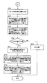
次に、図6〜図8に示す帯域割り当て方法によって、各フローに対して使用可能な帯域幅を割り当てる例について説明する。まず、通信端末10の通信管理部101bにおける帯域割り当てについて詳述する。 Next, an example of allocating usable bandwidth to each flow by the bandwidth allocation method shown in FIGS. First, bandwidth allocation in the
まず、通信端末10の通信管理部101bでは、表8に示すフロー情報を参照して、図6のフローチャートにおいて、最低限の使用要求帯域幅(BW(MIN))即ち表8における最低使用要求帯域幅(BW(1))が示す音声用帯域幅30kbps及び映像用帯域幅100kbps、単位時間当たりの最低使用要求パケット数として音声用10pps及び映像用8ppsを割り当てる(ステップST01)。 First, with reference to the flow information shown in Table 8, the
その結果、最低限の使用要求帯域幅(BW(MIN))としてフロー1及びフロー2に割り当てた合計使用要求帯域幅のリソースが、フローの方向が下り回線方向であることを考慮して、パス情報の使用可能帯域幅(BW(可用))から減算されて、今後利用可能なパス情報の使用可能帯域幅(BW(可用))として更新され、更に、NIC情報の下り方向の使用可能帯域幅(BW(下り−余り))から減算されて、今後利用可能なNIC情報の使用可能帯域幅(BW(下り−余り))として更新される(ステップST02)。 As a result, the resource of the total use request bandwidth allocated to the
同様に、最低限の使用要求帯域幅(BW(MIN))としてフロー1及びフロー2に割り当てた単位時間当たりの合計使用要求パケット数のリソースが、フローの方向が下り回線方向であることを考慮して、パス情報の単位時間当たり使用可能パケット数(pps(可用))から減算されて、今後利用可能なパス情報の単位時間当たりの使用可能パケット数(pps(可用))として更新され、更に、NIC情報の下り方向の単位時間当たり使用可能パケット数(pps(下り−余り))から減算されて、今後利用可能なNIC情報の単位時間当たり使用可能パケット数(pps(下り−余り))として更新される(ステップST03)。 Similarly, the resource of the total use request packet number per unit time allocated to the
次に、今後利用可能なパス情報の使用可能帯域幅(BW(可用))、単位時間当たりの使用可能パケット数(pps(可用))、今後利用可能なNIC情報の使用可能帯域幅(BW(下り−余り))、単位時間当たりの使用可能パケット数(pps(下り−余り))のいずれも正数であるか否か、即ち、残りの使用可能帯域幅(BW(可用)、BW(下り−余り))、単位時間当たりの使用可能パケット数(pps(可用)、pps(下り−余り))がまだ残されているか否かを調べ(ステップST04)、正数ではない場合(ステップST04のNO)、先に割り当てた最低限の使用要求帯域幅(BW(MIN))を確保することができない場合であり、帯域割り当てに失敗したものとして、TV電話アプリケーション101dに対してエラーの旨を報告して、帯域割り当て処理を終了する(ステップST05)。 Next, usable bandwidth of path information that can be used in the future (BW (available)), number of usable packets per unit time (pps (available)), usable bandwidth of NIC information that can be used in the future (BW ( Downlink-Remainder)) and the number of usable packets per unit time (pps (Downlink-Remainder)) are positive numbers, that is, the remaining usable bandwidth (BW (available), BW (downlink) -Remainder)), whether or not the number of usable packets per unit time (pps (available), pps (downlink-remainder)) is still left (step ST04), and if it is not a positive number (step ST04) NO), the minimum use request bandwidth (BW (MIN)) allocated in advance cannot be secured, and it is assumed that the bandwidth allocation has failed and the
次に、図7のフローチャートにおいて、最高のクオリティが得られる最大の使用要求帯域幅(BW(MAX))即ち表8における最大使用要求帯域幅(BW(3))が示す音声用帯域幅120kbps及び映像用帯域幅1Mbps、単位時間当たりの最低使用要求パケット数として音声用60pps及び映像用80ppsを割り当てる(ステップST06)。 Next, in the flowchart of FIG. 7, the maximum required bandwidth (BW (MAX)) that provides the highest quality, that is, the
その結果、最大の使用要求帯域幅(BW(MAX))としてフロー1及びフロー2に割り当てた合計使用要求帯域幅のリソースが、フローの方向が下り回線方向であることを考慮して、パス情報の使用可能帯域幅(BW(可用))から減算されて、今後利用可能なパス情報の使用可能帯域幅(BW(可用))として算出され、更に、NIC情報の下り方向の使用可能帯域幅(BW(下り−余り))から減算されて、今後利用可能なNIC情報の使用可能帯域幅(BW(下り−余り))として算出される(ステップST07)。 As a result, the resource of the total use request bandwidth allocated to the
ここで、状態管理パラメータとは、図8に示す帯域割り当て処理をする場合についてループ処理からの脱出の有無を制御するためのパラメータのことであり、フロー情報の各フロー毎に対応付けて付加して設けている。ここで、各フロー毎の状態管理パラメータの初期値は「0」であるが、「規定ループ回数+1」に設定することにより、図8のループ処理から脱出することを指示している。 Here, the state management parameter is a parameter for controlling whether or not to escape from the loop processing when the bandwidth allocation processing shown in FIG. 8 is performed, and is added in association with each flow of the flow information. Provided. Here, the initial value of the state management parameter for each flow is “0”, but setting “prescribed loop count + 1” instructs to escape from the loop processing of FIG.
一方、今後利用可能なパス情報の使用可能帯域幅(BW(可用))、単位時間当たりの使用可能パケット数(pps(可用))のいずれかが正数ではない場合(ステップST09のNO)、先に割り当てた最大の使用要求帯域幅(BW(MAX))を確保することができない状態にある場合であり、ステップST01〜ST03で最低限の使用要求帯域幅(BW(MIN))の割り振りに成功しているパス情報の状態に一旦戻す(ステップST11)。 On the other hand, if any of the available bandwidth (BW (available)) and the number of available packets per unit time (pps (available)) is not a positive number (NO in step ST09), This is a case where the previously allocated maximum use request bandwidth (BW (MAX)) cannot be secured. In steps ST01 to ST03, the minimum use request bandwidth (BW (MIN)) is allocated. It returns to the state of the successful path information once (step ST11).
割り当て結果として、パス情報の残りの使用可能帯域幅やNIC情報の余りの使用可能帯域幅を算出した結果、図6及び図7のステップST04及びST09のいずれにおいても正数の値となるので(ステップST04のYES、ステップST09のYES)、音声用フロー1、映像用フロー2共に、最大使用要求帯域幅(BW(MAX)即ち表8のBW(3))の帯域幅BW、単位時間当たりのパケット数ppsを、フロー1、フロー2に対して割り当てて、帯域割り当て処理を終了する。 As a result of the allocation, the remaining usable bandwidth of the path information and the remaining usable bandwidth of the NIC information are calculated, so that a positive value is obtained in any of steps ST04 and ST09 in FIGS. YES in step ST04, YES in step ST09), the
発呼側通信端末10の通信管理部101bは、TV電話アプリケーション101dに対して、TV電話用として割り当てた割当(使用可能)帯域幅を通知する(シーケンスS90)。この結果、発呼側通信端末10のTV電話アプリケーション101dにおいては、今までは、シーケンスS83において最低レートの帯域幅を用いた音声だけで通信を開始していたが、通信相手の着呼側通信端末11のTV電話アプリケーション111dから、最高レートの音声用フロー1と、最高レートの映像用フロー2とを用いて、受信可能な状態になる。TV電話アプリケーション101dに帯域割り当てを行なった結果のフロー情報を表12に示す。 The
表12に示すように、音声用フロー1、映像用フロー2については、最大の使用要求帯域幅を割り当てているので、状態管理パラメータの値は、共に、「規定ループ回数+1」となる「5」が設定され、割当(使用可能)帯域幅を示す「BW(付与)」には、それぞれ、120kbps,1Mbpsが、また、単位時間当たりの割当(使用可能)パケット数を示す「pps(付与)」には、それぞれ、60pps,80ppsが設定される。 As shown in Table 12, since the maximum use request bandwidth is allocated to the
TV電話アプリケーション101dに対する帯域割り当てを終了した結果として、通信端末10の通信管理部101bにおいて、以降のアプリケーションからのフローの要求に備えて、ネットワークから当該通信端末10へ向かうパス1に関するパス情報の使用可能帯域幅(BW(可用))、単位時間当たりの使用可能パケット数(pps(可用))、及び、NIC100に関するNIC情報の使用可能帯域幅(BW(下り−余り))、単位時間当たり使用可能パケット数(pps(下り−余り))を更新して保存する。即ち、TV電話アプリケーション101dに実際に割り当てた帯域幅BWと単位時間当たりのパケット数ppsとを減算した結果得られたパス情報、NIC情報を、それぞれ表13、表14に示している。 As a result of ending the bandwidth allocation for the
ここで、表13に示すパス情報の使用可能帯域幅(BW(可用))は、実際に割り当てた割当(使用可能)帯域幅を減算した計算結果からは、880kbpsが得られるが、一方、単位時間当たりの使用可能パケット数(pps(可用))の算出結果としては、僅か20ppsしか残されていないため、使用可能帯域幅(BW(可用))についても、単位時間当たりのパケット数20ppsを受信可能な限界値である250kbpsに変更して設定している。 Here, the usable bandwidth (BW (available)) of the path information shown in Table 13 is 880 kbps from the calculation result obtained by subtracting the actually allocated (usable) bandwidth. As a result of calculating the number of usable packets per hour (pps (available)), only 20 pps remains, so the received bandwidth (BW (available)) is 20 pps per unit time. The value is set to 250 kbps which is a possible limit value.
更新したパス情報、NIC情報は、通信相手の着呼側通信端末11の通信管理部111bに対して送信されて(シーケンスS92)、着呼側通信端末11の通信管理部111bにて、通信端末10向けのパス情報、NIC情報の更新用として利用される(シーケンスS93)。 The updated path information and NIC information are transmitted to the
シーケンスS90において、割当(使用可能)帯域幅の通知を受け取った発呼側通信端末10のTV電話アプリケーション101dにおいては、着呼側通信端末11のTV電話アプリケーション111dに対して、SIP/SDPの「Re−INVITE」メッセージを用いて、下り方向のフローに関して、映像用に使用開始する映像コーデックと最低限度のレートで使用中の音声コーデックの変更とを要求するコーデック変更要求を送信する(シーケンスS94)。 In the sequence S90, the
このコーデック変更要求を受信した着呼側通信端末11のTV電話アプリケーション111dは、TV電話アプリケーション101dのコーデック変更要求に従ってコーデックの設定・変更を行ない、要求元の発呼側通信端末10のTV電話アプリケーション101dに対して、コーデックの変更を実施済みであり、変更後の帯域を用いた通信が可能である旨を示す200 OKレスポンスを、SIP/SDPに従って返送する(シーケンスS95)。 The
この結果、着呼側通信端末11→発呼側通信端末10方向のTV電話用のフローが決定する。しかる後、着呼側通信端末11のTV電話アプリケーション111dは、RTPに従って、TV電話の音声用フロー1と映像用フロー2とを帯域変更後の音声用コーデックと映像用コーデックを用いて、発呼側通信端末10のTV電話アプリケーション101dに対して送信する(シーケンスS96)。 As a result, the TV telephone flow in the direction of the called
次に、通信端末11の通信管理部111bにおける帯域割り当てについて説明する。即ち、発呼側通信端末10→着呼側通信端末11に関する帯域割り当てについて説明する。なお、本実施例においては、通信端末10の場合と同様に、図8におけるループ処理を繰り返す規定ループ回数は、4回とする。 Next, bandwidth allocation in the
まず、通信端末11の通信管理部111bでは、通信端末10の通信管理部101bにおける処理と同様に、表9に示すフロー情報を参照して、図6のフローチャートにおいて、最低限の使用要求帯域幅(BW(MIN))即ち表9における最低使用要求帯域幅(BW(1))が示す音声用帯域幅30kbps及び映像用帯域幅100kbps、単位時間当たりの最低使用要求パケット数として音声用10pps及び映像用8ppsを割り当てる(ステップST01)。 First, the
割り当て結果として、パス情報の残りの使用可能帯域幅やNIC情報の余りの使用可能帯域幅を算出した結果を、表15のパス情報、表16のNIC情報に示す。 The results of calculating the remaining usable bandwidth of the path information and the remaining usable bandwidth of the NIC information as the allocation results are shown in the path information in Table 15 and the NIC information in Table 16.
表15、表16に示すように、図6のステップST04において、算出結果が正数の値となるので(ステップST04のYES)、次に、図7のフローチャートにおいて、最高のクオリティが得られる最大の使用要求帯域幅(BW(MAX))即ち表9における最大使用要求帯域幅(BW(3))が示す音声用帯域幅120kbps及び映像用帯域幅1Mbps、単位時間当たりの最低使用要求パケット数として音声用60pps及び映像用80ppsを割り当てる(ステップST06)。 As shown in Tables 15 and 16, since the calculation result becomes a positive value in step ST04 of FIG. 6 (YES in step ST04), the maximum quality that can provide the highest quality is next obtained in the flowchart of FIG. Use bandwidth (BW (MAX)), that is, the maximum use request bandwidth (BW (3)) in Table 9 indicates the
最大の使用要求帯域幅(BW(MAX))の割り当て結果として、パス情報の残りの使用可能帯域幅やNIC情報の余りの使用可能帯域幅を算出した結果、パス情報のパス2についてはパス1よりも狭い使用可能帯域幅であるので、図7のステップST09において、パス情報の残りの使用可能帯域幅(BW(可用))、単位時間当たりの使用可能パケット数(pps(可用))のいずれも正数の値とならなく(ステップST09のNO)、最大の使用要求帯域幅(BW(MAX))を割り当てることができないことが判明する。 As a result of allocating the maximum use request bandwidth (BW (MAX)), the remaining usable bandwidth of the path information and the remaining usable bandwidth of the NIC information are calculated. Since the available bandwidth is narrower than that, in step ST09 of FIG. 7, any of the remaining available bandwidth (BW (available)) of path information and the number of available packets per unit time (pps (available)) Is not a positive value (NO in step ST09), and it is found that the maximum use request bandwidth (BW (MAX)) cannot be allocated.
そこで、図8に示す帯域割り当て方法に沿って、パス2に関する割当(使用可能)帯域幅を決定することになる。以降の説明に当たって参考のため、図5に、本実施例において図8の帯域割り当て方法によって割り当てられていく各フロー(フロー3及びフロー4)の帯域割り当て状況を模式的に示している。 Therefore, the allocated (usable) bandwidth for
まず、表9に示すフロー情報においては、現在、音声用フロー3,映像用フロー4のいずれのフローについても、状態管理パラメータの値は初期値の「0」であるので、より優先度の高い音声用フロー3に注目して(ステップST12)、最大使用要求帯域幅(BW(MAX)即ち表9のBW(3)の使用要求帯域幅120kbps及び単位時間当たりの使用要求パケット数60pps)となるために必要とする残りの使用要求帯域幅90kbps及び単位時間当たりの使用要求パケット数50ppsと、表15に示すパス情報のパス2の使用可能帯域幅(BW(可用))の半分435kbps及び単位時間当たり使用可能パケット数(pps(可用))の半分41ppsとを比較する(ステップST13)。 First, in the flow information shown in Table 9, since the value of the state management parameter is the initial value “0” for both the
その結果、最大使用要求帯域幅(BW(MAX))の使用要求帯域幅120kbpsになるために必要とする残りの帯域幅90kbpsは、パス2の使用可能帯域幅(BW(可用))の半分435kbps以下であるが、最大使用要求帯域幅(BW(MAX))の単位時間当たりの使用要求パケット数60ppsになるための残り50ppsは、パス2の単位時間当たり使用可能パケット数(pps(可用))の半分41pps以上になっていることが分かる。 As a result, the remaining bandwidth of 90 kbps necessary for the maximum required bandwidth (BW (MAX)) to be 120 kbps is 435 kbps, which is half of the available bandwidth (BW (available)) of
従って、割当(使用可能)帯域幅BWとしては、フロー3が要求する最大使用要求帯域幅(BW(MAX))即ち使用要求帯域幅BW(3)ではなく、表15に示すパス情報における使用可能帯域幅の半分の435kbps,41ppsを追加して割り当てる(ステップST18)。しかし、追加して割り当てた帯域幅435kbpsと先に割り当て済みの最小使用要求帯域幅30kbpsとの合計は、フロー3の最大使用要求帯域幅(BW(MAX)即ちBW(3))の120kbpsよりも大きいので、帯域幅については、最大使用要求帯域幅(BW(MAX))即ち使用要求帯域幅BW(3)の120kbpsを割り当てる。 Therefore, the allocated (usable) bandwidth BW is not the maximum use request bandwidth (BW (MAX)) required by the
即ち、フロー3に関しては、割当(使用可能)帯域幅として、最低限使用要求帯域幅(BW(MIN))として先に割り当て済みの割当(使用可能)帯域幅30kbpsを置換して、最高のクオリティが得られる最大使用要求帯域幅(BW(MAX))即ち使用要求帯域幅BW(3)の120kbpsを割り当て、単位時間当たり割当(使用可能)パケット数としては、最低限使用要求帯域幅(BW(MIN))として先に割り当て済みの単位時間当たり割当(使用可能)パケット数10ppsに、更に41ppsを加えた合計51ppsが割り当てられる(図5におけるフロー3のループ回数1の状態)。 That is, with respect to the
次に、フロー3の次の優先度であり、状態管理パラメータがまだ「0」の状態にあるフロー4に関する帯域割り当て処理に移行する。
映像用フロー4の最大使用要求帯域幅(BW(MAX)即ち表9のBW(3)の使用要求帯域幅1Mbps及び単位時間当たりの使用要求パケット数80pps)となるために必要とする残りの使用要求帯域幅900kbps及び単位時間当たりの使用要求パケット数72ppsのいずれも、フロー3の割当(使用可能)帯域幅を割り当てた後のパス2の使用可能帯域幅(BW(可用))780kbpsの半分及び単位時間当たり使用可能パケット数(pps(可用))41ppsの半分よりも小さい値ではないので(ステップST13のNO)、パス情報における使用可能帯域幅(BW(可用))の半分390kbps及び単位時間当たりの使用可能パケット数(pps(可用))の半分21ppsを追加して割り当てる(ステップST18)。Next, the flow shifts to the bandwidth allocation process for the
Remaining usage required to reach the maximum required bandwidth of the video flow 4 (BW (MAX), that is, the required bandwidth of 1 Mbps for the BW (3) in Table 9 and the number of usage request packets of 80 pps per unit time)) Both of the requested bandwidth 900 kbps and the use request packet number 72 pps per unit time are half of the available bandwidth (BW (available)) 780 kbps of the
その結果、注目するフローに関して追加して割り当てた半帯域幅のリソースが、フローの方向が下り回線方向であることを考慮して、パス情報の使用可能帯域幅(BW(可用))から減算されて、今後利用可能なパス情報の使用可能帯域幅(BW(可用))として更新され、更に、最低限使用可能帯域幅(BW(MIN))により先に更新済みのNIC情報の下り方向の使用可能帯域幅(BW(下り−余り))から減算されて、今後利用可能なNIC情報の使用可能帯域幅(BW(下り−余り))として更新される(ステップST19)。 As a result, the additional half-bandwidth resource for the flow of interest is subtracted from the available bandwidth (BW (available)) in the path information, taking into account that the flow direction is the downlink direction. Then, it is updated as the usable bandwidth (BW (available)) of the path information that can be used in the future, and further, the NIC information that has been updated earlier with the minimum usable bandwidth (BW (MIN)) is used in the downstream direction. It is subtracted from the available bandwidth (BW (downward-remainder)) and updated as the available bandwidth (BW (downward-remainder)) of NIC information that can be used in the future (step ST19).
同様に、注目するフローに関して追加して割り当てた単位時間当たりの使用可能パケット数のリソースが、フローの方向が下り回線方向であることを考慮して、パス情報の単位時間当たりの使用可能パケット数(pps(可用))から減算されて、今後利用可能なパス情報の単位時間当たりの使用可能パケット数(pps(可用))として更新される。更に、最低限使用要求帯域幅(BW(MIN))により先に更新済みのNIC情報の下り方向の単位時間当たりの使用可能パケット数(pps(下り−余り))から減算されて、今後利用可能なNIC情報の単位時間当たりの使用可能パケット数(pps(下り−余り))として更新される(ステップST20)。なお、この更新結果のパス情報,NIC情報の表示は省略する。 Similarly, the number of usable packets per unit time of the path information, considering that the resource of the number of usable packets per unit time allocated additionally for the flow of interest is the downlink direction. Subtracted from (pps (available)) and updated as the number of usable packets per unit time (pps (available)) of path information that can be used in the future. Furthermore, it is subtracted from the number of usable packets per unit time (pps (downlink-remainder)) in the downlink direction of the NIC information that has been updated earlier by the minimum required bandwidth (BW (MIN)), and can be used in the future NIC information is updated as the number of usable packets per unit time (pps (downlink-remainder)) (step ST20). The display of the path information and NIC information as the update result is omitted.
この結果、フロー4に関しては、最低限使用要求帯域幅(BW(MIN))として先に割り当て済みの割当(使用可能)帯域幅100kbps、単位時間当たり割当(使用可能)パケット数8ppsに、それぞれ更に390kbps,21ppsを加えた合計490kbps,29ppsの帯域幅が、割当(使用可能)帯域幅、単位時間当たり割当(使用可能)パケット数として割り当てられる(図5におけるフロー4のループ回数1の状態)。 As a result, with respect to the
次に、状態管理パラメータの値が「1」で、優先度が高いフロー3の帯域割り当てに戻って、フロー3の単位時間当たり割当(使用可能)パケット数は、まだ、最大使用要求帯域幅(BW(MAX))即ち使用要求帯域幅BW(3)の60ppsに至っていないので、2回目のループ処理(追加帯域幅割り当て処理)に移行する。 Next, the state management parameter value is “1”, and the flow returns to the bandwidth allocation of the
2回目のループ処理結果として、フロー3の単位時間当たり割当(使用可能)パケット数については、最大使用要求帯域幅(BW(MAX))即ち使用要求帯域幅BW(3)の60ppsになるまでの残りの割り当てパケット数9ppsが、1回目の割り当て処理後のパス2の単位時間当たりの使用可能パケット数(pps(可用))の半分10pps以下になっているので、フロー3が要求する最大使用要求帯域幅(BW(MAX))即ち使用要求帯域幅BW(3)の単位時間当たり使用要求パケット数60ppsを割り当てる(ステップST14)。 As a result of the second loop processing, with respect to the number of allocated (usable) packets per unit time of
この結果、フロー3の割当(使用可能)帯域幅は、フロー3が要求する最大使用要求帯域幅(BW(MAX))即ち使用要求帯域幅BW(3)の120kbps,60ppsが割り当てられ、状態管理パラメータの値も、「規定ループ回数+1」の「5」に設定されて、フロー3に関する帯域割り当て処理を終了する(図5におけるフロー3のループ回数2の状態)。 As a result, the allocated (usable) bandwidth of the
その結果、注目するフローに関して割り当てる割当(使用可能)帯域幅のリソースのうち、最低限使用要求帯域幅(BW(MIN))として先に割り当て済みの割当(使用可能)帯域幅を差し引いた残りの帯域幅が、フローの方向が下り回線方向であることを考慮して、パス情報の使用可能帯域幅(BW(可用))から減算されて、今後利用可能なパス情報の使用可能帯域幅(BW(可用))として更新される。更に、最低限使用要求帯域幅(BW(MIN))により先に更新済みのNIC情報の下り方向の使用可能帯域幅(BW(下り−余り))から減算されて、今後利用可能なNIC情報の使用可能帯域幅(BW(下り−余り))として更新される(ステップST15)。 As a result, out of the allocated (usable) bandwidth resources to be allocated for the flow of interest, the remaining bandwidth obtained by subtracting the allocated (usable) bandwidth previously allocated as the minimum required bandwidth (BW (MIN)) Considering that the flow direction is the downlink direction, the bandwidth is subtracted from the usable bandwidth (BW (available)) of the path information, and the usable bandwidth (BW of the path information that can be used in the future) (Available)). Further, the NIC information that has been previously updated is subtracted from the available bandwidth (BW (downward-remainder)) in the downlink direction of the previously updated NIC information by the minimum required bandwidth (BW (MIN)). It is updated as an available bandwidth (BW (downward-remainder)) (step ST15).
同様に、注目するフローに関して割り当てる単位時間当たりの割当(使用可能)パケット数のリソースのうち、最低限使用要求帯域幅(BW(MIN))として先に割り当て済みの単位時間当たりの割当(使用可能)パケット数を差し引いた残りのパケット数が、フローの方向が下り回線方向であることを考慮して、パス情報の単位時間当たりの使用可能パケット数(pps(可用))から減算されて、今後利用可能なパス情報の単位時間当たりの使用可能パケット数(pps(可用))として更新される。更に、最低限使用要求帯域幅(BW(MIN))により先に更新済みのNIC情報の下り方向の単位時間当たりの使用可能パケット数(pps(下り−余り))から減算されて、今後利用可能なNIC情報の単位時間当たりの使用可能パケット数(pps(下り−余り))として更新される(ステップST16)。 Similarly, among the resources of the number of allocation (usable) packets per unit time allocated for the flow of interest, the allocation per unit time (usable) that has been previously allocated as the minimum use request bandwidth (BW (MIN)) ) The remaining number of packets minus the number of packets is subtracted from the number of usable packets per unit time (pps (available)) in consideration of the fact that the flow direction is the downlink direction. The available path information is updated as the number of usable packets per unit time (pps (available)). Furthermore, it is subtracted from the number of usable packets per unit time (pps (downlink-remainder)) in the downlink direction of the NIC information that has been updated earlier by the minimum required bandwidth (BW (MIN)), and can be used in the future. NIC information is updated as the number of usable packets per unit time (pps (downlink-remainder)) (step ST16).
次に、ステップST17に移行して、フローの要求する最大使用要求帯域幅(BW(MAX))が割り振られた場合には、その旨を示すために「規定ループ回数+1」をフローの状態管理パラメータとしてフロー情報に保持する(ステップST17)。 Next, when the flow proceeds to step ST17 and the maximum required bandwidth (BW (MAX)) requested by the flow is allocated, “specified loop count + 1” is used to indicate that fact. The flow information is held as a parameter (step ST17).
以降、フロー4に関して、図8の帯域割り当て方法に示すループ処理を規定ループ回数4回まで繰り返すことにより、割当(使用可能)帯域幅、単位時間当たり割当(使用可能)パケット数として、832kbps,39ppsが割り当てられる(図5におけるフロー4のループ回数4の状態)。ここで、TV電話アプリケーション111dから要求されたフロー4に関する使用要求帯域幅のうち、算出された割り当て可能な割当(使用可能)帯域幅832kbps、単位時間当たり割当(使用可能)パケット数39ppsを超えない条件の下で最も高いクオリティが得られる使用要求帯域幅BW(2)の300kbps,24ppsが、実際にフロー4に割り当てるべき割当(使用可能)帯域幅として決定される。 Thereafter, with respect to the
以上の帯域割り当て方法により各フローに対して割り当てられた割当(使用可能)帯域幅BW、単位時間当たり割当(使用可能)パケット数ppsは、優先する音声ストリームのフローについては、それぞれ、最高のクオリティが得られる最大使用要求帯域幅(BW(MAX))即ち使用要求帯域幅(BW(3))であり、一方、映像ストリームのフローについては、それぞれ、最低限の使用要求帯域幅(BW(MIN))即ち使用要求帯域幅(BW(1))と最大使用要求帯域幅(BW(MAX))即ち使用要求帯域幅(BW(4))との間の帯域幅である。 The allocation (usable) bandwidth BW and the number of allocated (usable) packets per unit time pps assigned to each flow by the above bandwidth allocation method are the highest quality for the priority audio stream flow. Is the maximum required bandwidth (BW (MAX)), that is, the required bandwidth (BW (3)), while the minimum required bandwidth (BW (MIN) )), That is, a bandwidth between the use request bandwidth (BW (1)) and the maximum use request bandwidth (BW (MAX)), that is, the use request bandwidth (BW (4)).
ここで、フロー情報として要求している使用要求帯域幅として、割当(使用可能)帯域幅に該当するものは存在していない場合は、ネットワーク状況として割り当て可能な帯域幅以下で最良の品質が得られる使用要求帯域幅とし、使用要求帯域幅(BW(2))となる。即ち、この使用要求帯域幅(BW(2))よりも1つ上の使用要求帯域幅(BW(3))を割り当てることができない限り、この使用要求帯域幅(BW(2))以上の帯域幅を割り当てても無駄になるだけである。 Here, if there is no bandwidth that can be allocated (usable) as the requested bandwidth requested as flow information, the best quality is obtained below the bandwidth that can be allocated as the network status. The required usage bandwidth (BW (2)). That is, unless the usage request bandwidth (BW (3)) that is one higher than the usage request bandwidth (BW (2)) can be allocated, the bandwidth that is equal to or greater than the usage request bandwidth (BW (2)). Allocating a width is just useless.
従って、フロー4に関しては、前述したように、多少の余裕を与えるようにしても良いが、TV電話アプリケーション101dから要求されている使用要求帯域幅(BW(2))に示す1Mbps、85ppsを割り振ることとし、フロー2に関する割当(使用可能)帯域幅として算出された使用要求帯域幅(BW(2))を超える帯域幅については、割り当てを取り消して開放し、今後利用するフローに対して使用可能な使用可能帯域幅(BW(可用))、単位時間当たり使用可能パケット数(pps(可用))、また、NIC100として使用可能な使用可能帯域幅(BW(下り−余り))、単位時間当たり使用可能パケット数(pps(下り−余り))に返還する(ステップST23)。しかる後、帯域割り当て処理を終了する(ステップST24)。 Accordingly, with regard to the
帯域の割り当て処理が終了すると、着呼側通信端末11の通信管理部111bは、TV電話アプリケーション111dに対して、TV電話用として割り当てた割当(使用可能)帯域幅を通知する(シーケンスS91)。この結果、着呼側通信端末11のTV電話アプリケーション111dにおいては、今までは、シーケンスS83において最低レートの帯域幅を用いた音声だけで通信を開始していたが、通信相手の発呼側通信端末10のTV電話アプリケーション101dから、使用要求帯域幅(BW(2))により割り当てられた割当(使用可能)帯域幅の音声用フロー3と映像用フロー4とを、受信可能な状態になる。 When the bandwidth allocation process is completed, the
以上により、音声用フロー1については、最大使用要求帯域幅(BW(MAX))即ち使用要求帯域幅(BW(3))の帯域幅120kbps,単位時間当たりのパケット数60ppsを、映像用フロー2については、使用要求帯域幅(BW(2))の帯域幅300kbps,単位時間当たりのパケット数24ppsを割り当てることになる。 As described above, with respect to the
このように、音声用フロー3と映像用フロー4とのコーデックを両者で異なるクオリティで制御することが可能な場合には、前述したように、音声用フロー3については、最高のクオリティが得られる使用要求帯域幅(BW(MAX)即ち表9のBW(3))を割り当て、映像用フロー4については、最高のクオリティとはならないが、使用可能とされる範囲で最高のクオリティとなる使用要求帯域幅(BW2))を割り当てることができる。 As described above, when the codec of the
一方、音声用フロー3と映像用フロー4との両者のコーデックを異なるクオリティで制御することができない場合には、両者が同時に使用可能となるクオリティである使用要求帯域幅(BW2))を割り当てることになり、音声用フロー3として先に割り当てていた割当(使用可能)帯域幅(120kbps,60pps)を、使用要求帯域幅BW(2)の90kbps,30ppsに変更して割り当て直す。音声用フロー3と映像用フロー4とで同一のクオリティのコーデックを用いて制御する場合において、TV電話アプリケーション111dに対して帯域割り当てを行なった結果のフロー情報を表17に示す。 On the other hand, if the codec of both the
以上のように、TV電話アプリケーション111dに対する帯域割り当てを終了した結果として、通信端末11の通信管理部111bにおいて、以降のアプリケーションからのフローの要求に備えて、ネットワークから当該通信端末11へ向かうパス2に関するパス情報の使用可能帯域幅(BW(可用))、単位時間当たりの使用可能パケット数(pps(可用))、及び、NIC110に関するNIC情報の使用可能帯域幅(BW(下り−余り))、単位時間当たり使用可能パケット数(pps(下り−余り))を更新して保存する。 As described above, as a result of ending the bandwidth allocation for the
即ち、音声用フロー3と映像用フロー4とで同一のクオリティが得られるように帯域幅を割り当てた場合において、TV電話アプリケーション111dに実際に割り当てた帯域幅BWと単位時間当たりのパケット数ppsとを減算した結果得られたパス情報、NIC情報を、それぞれ表18、表19に示している。 That is, when bandwidth is allocated so that the same quality can be obtained in the
更新したパス情報、NIC情報は、通信相手の発呼側通信端末10の通信管理部101bに対して送信されて(シーケンスS93)、発呼側通信端末10の通信管理部101bにて、通信端末11向けのパス情報、NIC情報の更新用として利用される。 The updated path information and NIC information are transmitted to the
シーケンスS91において、割当(使用可能)帯域幅の通知を受け取った着呼側通信端末11のTV電話アプリケーション111dにおいては、発呼側通信端末10のTV電話アプリケーション101dに対して、SIP/SDPの「Re−INVITE」メッセージを用いて、下り方向のフローに関して、映像用に使用開始する映像コーデックと最低限度のレートで使用中の音声コーデックの変更とを要求するコーデック変更要求を送信する(シーケンスS97)。 In the sequence S91, the
このコーデック変更要求を受信した発呼側通信端末10のTV電話アプリケーション101dは、TV電話アプリケーション111dのコーデック変更要求に従ってコーデックの設定・変更を行ない、要求元の着呼側通信端末11のTV電話アプリケーション111dに対して、コーデックの変更を実施済みであり、変更後の帯域を用いた通信が可能である旨を示す200 OKレスポンスを、SIP/SDPに従って返送する(シーケンスS98)。 The
この結果、発呼側通信端末10→着呼側通信端末11方向のTV電話用のフローが決定する。しかる後、発呼側通信端末10のTV電話アプリケーション101dは、RTPに従って、TV電話の音声用フロー3と映像用フロー4とを帯域変更後の音声用コーデックと映像用コーデックを用いて、着呼側通信端末11のTV電話アプリケーション111dに対して送信する(シーケンスS99)。 As a result, the TV phone flow in the direction from the calling
なお、シーケンスS92,S93において、通信端末10,11の通信管理部101b、111b間でパス情報、NIC情報を送受信し合うことにより、それぞれで、パス1及びパス2、NIC100及びNIC110がマージされ、パス情報(パス管理表)、NIC情報(NIC管理表)が更新される。これにより、以降の通信においては、通信相手の通信端末10,11における通信管理部101b、111bそれぞれが、互いのパス情報、NIC情報を認識することができる状態になっている。マージされた更新後のパス情報(パス管理表)、NIC情報(NIC管理表)を、それぞれ、表20、表21に示す。 In the sequences S92 and S93, the path information and the NIC information are transmitted and received between the
而して、現在のネットワーク状況に応じた最適な帯域を用いた通信が可能となるように、使用可能な帯域幅が割り当てられ、割り当てられた割当(通信可能)帯域幅にマッチしたコーデックを用いて、通信端末10,11間のTV電話の通信が可能となる。 Thus, a usable bandwidth is allocated so that communication using an optimum band according to the current network situation is possible, and a codec that matches the allocated (communication) allocated bandwidth is used. Thus, videophone communication between the
(第3の実施例)
本実施例においては、通信端末間でインターネットを介してTV電話(テレビ電話)を行なっている最中において、一方の通信端末が動画サーバから動画を受信する動画ビューアアプリケーションを起動した場合を例に取って、図9に示すシステム構成図を用いて説明する。ここに、図9は、本発明に係る帯域割り当て方法の第3の実施例を説明するためのシステム構成図であり、インターネット30を経由して互いにTV電話を行なう通信端末10,11と、インターネット30を経由して動画ストリーミングデータを配信する動画サーバ40が存在する場合を模式的に示している。(Third embodiment)
In this embodiment, the case where one communication terminal activates a video viewer application for receiving a video from a video server during a videophone call (videophone) between the communication terminals via the Internet is taken as an example. This will be described with reference to the system configuration diagram shown in FIG. FIG. 9 is a system configuration diagram for explaining a third embodiment of the bandwidth allocating method according to the present invention. The
図9のシステム構成図において、通信端末10,11のそれぞれには、図3のシステム構成図と全く同様の機能ブロックが備えられているものであり、その詳細な説明は省略する。但し、以降の本実施例の説明に用いるアプリケーション例として、通信端末11との間でTV電話中に動画サーバ40と通信を行なう通信端末10には、動画サーバ40から配信される動画ストリーミングを受信するための動画ビューアアプリケーション101cとTV電話用のTV電話アプリケーション101dとの双方を図示している。 In the system configuration diagram of FIG. 9, each of the
以下、図9に示すシステム構成図における通信端末10,11のTV電話アプリケーション101d,111d間の通話中に、動画ビューアアプリケーション101cを起動して動画サーバ40から配信される動画ストリーミングデータを受信する場合における帯域割り当て方法について、図10に示すシーケンスチャートを用いて説明する。 Hereinafter, when the
ここに、図10は、本発明に係る帯域割り当て方法の第3の実施例を説明するためのシーケンスチャートであり、通信端末10,11間でTV電話中に、ネットワークから通信端末10に向かう下り方向のフローにおける割当(使用可能)帯域幅を選択する場合を例に取って、図9に示す通信端末10,11間及び通信端末10−動画サーバ40間で送受信されるデータのシーケンスを示している。また、通信端末10の内部における複数のアプリケーション(TV電話アプリケーション101d及び動画ビューアアプリケーション101c)と通信管理部101bとの間のデータの送受信についても示している。 FIG. 10 is a sequence chart for explaining the third embodiment of the bandwidth allocation method according to the present invention. During the videophone call between the
なお、本実施例における帯域割り当て方法の説明に当たっては、説明を簡単にするために、TV電話に関しては、通信端末10の下り方向のみのフローを考慮し、図10には、下り方向のフローに関連するシーケンスのみを示し、更に、下りフローの通信速度即ち使用可能帯域幅BWのみを説明するものとし、単位時間当たりのパケット数ppsに関しては説明を省略している。 In the description of the bandwidth allocation method in the present embodiment, in order to simplify the description, regarding the TV phone, only the flow in the downlink direction of the
通信端末10−通信端末11との間のTV電話において使用可能な帯域幅を示す使用可能帯域幅8Mbpsがネットワーク情報として得られている状況下において、第2の実施例の場合と同様に、通信端末10の下りフローに対して、音声用フロー用として120kbps、映像用フロー用として1Mbpsの最大使用要求帯域幅(BW(MAX))が割当(使用可能)帯域幅として割り振りが行なわれた場合のフロー情報を表22に示す。 In the situation where the
この帯域割り当て結果として、作成されたパス情報及びNIC情報に関して、通信端末10の下り方向に関連する部分のみを、表23及び表24に示す。表23のパス情報におけるパス2は、通信端末10における上り方向のパスであり、また、表24のNIC情報におけるNIC100の上り、NIC110の下りも、通信端末10における上り方向の情報であり、通信端末10に対する下り方向の帯域割り当てを説明する本実施例においては無関係であり、それぞれの表には示していない。 As a result of this bandwidth allocation, Tables 23 and 24 show only portions related to the downlink direction of the
このような帯域割り当て結果により選択されたコーデックを用いて、通信端末10のTV電話アプリケーション101dは、通信端末11のTV電話アプリケーション111dとの間でTV電話を行ない、TV電話アプリケーション111dからのTV電話用のデータを受信している。 Using the codec selected based on the band allocation result, the
このTV電話の最中に(シーケンスS101)、通信端末10が動画サーバ40から動画ストリーミングデータの配信を要求すると、通信端末10は、動画サーバ40とのネゴシエーション(RTSP−DESCRIBEメッセージとSIP/SDP 200 OKレスポンスの交換)が正常に終了すれば(シーケンスS102,S103)、新たなフロー5(音声用下りフロー),フロー6(映像用下りフロー)、新たなパス3(動画サーバ40からの下りパス)・NIC400(動画サーバ40のNIC)とが追加されるようになる。 During the videophone call (sequence S101), when the
この結果、通信端末10の通信管理部101bは、動画ビューアアプリケーション101cからフロー情報を受け取り(シーケンスS104)、動画サーバ40の通信管理部401bとの間で、NIC情報、パス情報の交換を行なうと共に(シーケンスS105,S106)、例えば、動画サーバ40との間でEND−ENDで通信可能な帯域幅をネットワーク情報として取得することにより(シーケンスS107,S108)、通信管理部101bには、新たな通信の管理対象として、動画サーバ40との新たなフロー5,6、パス3、NIC400が追加される。この結果として、既に帯域幅を割り当て済みのフロー1,2も含めて、帯域の割り当てをし直すことになる。 As a result, the
そのため、フロー情報(フロー管理表)、パス情報・NIC情報(パス管理表・NIC管理表)は、フロー、パス、NICの各帯域の割り当てについて初期状態に一旦戻されて、割り当てが済んでいない状態に書き換えられる。書き換え後のフロー情報、パス情報、NIC情報を、それぞれ、表25、表26、表27に示す。なお、表25のフロー情報のBW(付与)欄には、フロー1,2にTV電話用として既に割り当てられていた割当(使用可能)帯域幅が残されて記録されているが、状態管理パラメータの値は、いずれも「0」の初期値に復帰して、新たに帯域を割り当て直す状態に設定されている。 Therefore, the flow information (flow management table) and path information / NIC information (path management table / NIC management table) are temporarily returned to the initial state with respect to the allocation of each band of the flow, path, and NIC, and the allocation is not completed. Rewritten to state. The rewritten flow information, path information, and NIC information are shown in Table 25, Table 26, and Table 27, respectively. In the BW (grant) column of the flow information in Table 25, the allocation (usable) bandwidth that has already been allocated for the video phone in the
このような状況において、各フローの帯域割り当て順序を示す優先度としては、表25のフロー情報に示すように、TV電話の音声用フロー1→動画配信の映像用フロー6→TV電話の映像用フロー2→動画配信の音声用フロー5の順番と設定されており、更に、TV電話用のフロー1,2についてはパス1を利用し、動画ストリーミング配信用のフロー5,6については、パス3を利用するものと仮定する。 In such a situation, as shown in the flow information in Table 25, the priority indicating the bandwidth allocation order of each flow is as follows: TV
ここで、図6〜図8に示した帯域割り当て方法を用いて、各フローに対して使用可能な通信帯域幅を割当(使用可能)帯域幅として割り振ることになるが、本実施例においては、通信端末10の通信相手が、通信端末11と動画サーバ40と複数になったため、各フローの帯域割り当て用として参照するパス情報の使用可能帯域幅(BW(可用))・NIC情報の使用可能帯域幅(BW(下り−余り))について、新たに、最小使用可能帯域幅(BW(余り))という概念を導入する。 Here, using the bandwidth allocation method shown in FIG. 6 to FIG. 8, the communication bandwidth that can be used for each flow is allocated as an allocated (usable) bandwidth. In this embodiment, Since there are a plurality of communication partners of the
この最小使用可能帯域幅(BW(余り))とは、注目しているパスについて、パス情報の使用可能帯域幅(BW(可用))、当該通信端末10自身におけるNIC情報の使用可能帯域幅(BW(下り−余り))、通信相手の通信端末11又は動画サーバ40に関するNIC情報の使用可能帯域幅(BW((上り−余り))のうち、いずれか最も小さい値とするものである。本実施例の場合、この時点では、表26のパス情報の最小使用可能帯域幅(BW(余り))に示すように、パス情報の使用可能帯域幅(BW(可用))8Mbpsが最小のものとして設定される。 The minimum usable bandwidth (BW (remainder)) is the path information usable bandwidth (BW (available)) and the NIC information usable bandwidth (in the
図8に示す帯域幅の追加割り当て処理に対して、前述のような最小使用可能帯域幅(BW(余り))の概念を適用した場合の帯域割り当て方法について、図11に示す。即ち、図11は、本発明に係る帯域割り当て方法の図7に続く第3の実施例における処理を説明するためのフローチャートであり、最大使用要求帯域幅(BW(MAX))を割り当てられない場合の追加帯域幅割り当て処理を示す図8のフローチャートに対して、新たに最小使用可能帯域幅(BW(余り))を求めるためのステップST12Aの処理を追加したものである。このステップST12A以外の処理については、図8と全く同様である。次に、図6,7及び図11の帯域割り当て方法を用いて、各フローに対して帯域を割り当てる割り当て方法について説明する。 FIG. 11 shows a bandwidth allocation method when the concept of minimum usable bandwidth (BW (remainder)) as described above is applied to the additional bandwidth allocation processing shown in FIG. That is, FIG. 11 is a flowchart for explaining the processing in the third embodiment following FIG. 7 of the bandwidth allocation method according to the present invention, in the case where the maximum use required bandwidth (BW (MAX)) cannot be allocated. The process of step ST12A for newly obtaining the minimum usable bandwidth (BW (remainder)) is added to the flowchart of FIG. 8 showing the additional bandwidth allocation process. Processing other than this step ST12A is exactly the same as in FIG. Next, an allocation method for allocating a bandwidth to each flow will be described using the bandwidth allocation methods of FIGS.
まず、実施例2の場合と同様に、図6において、最低限の最低使用要求帯域幅(BW(MIN)即ち表25のBW(1))の各フローの帯域幅(パス1用として130kbps、パス3用として330kbps)を割り当てることが可能か調査する。この結果、最低使用要求帯域幅(BW(MIN))の割り当て処理は、エラーとはならないので(ステップST04のYES)、パス1用として130kbps、パス3用として330kbpsを割り当てる。 First, as in the case of the second embodiment, in FIG. 6, the bandwidth of each flow with the minimum minimum required bandwidth (BW (MIN), that is, BW (1) in Table 25) (130 kbps for path 1) It is investigated whether it is possible to allocate 330 kbps) for
割り当てた結果、パス1の残りの使用可能帯域幅(BW(可用))は、パス1として割り当てた帯域幅分減少して、7.87Mbpsとなり、パス3の残りの使用可能帯域幅(BW(可用))は、9.67Mbpsとなる。一方、TV電話用のパス1と動画配信用のパス3とを共用するNIC100に関する余りの使用可能帯域幅(BW(下り−余り))は、パス1とパス3とに割り当てた合計帯域分減少して、10.54Mbpsとなり、パス1用のみに関与するNIC110の余りの使用可能帯域幅(BW(上り−余り))は、10.87Mbpsとなる。また、パス3用のみに関与するNIC400の余りの使用可能帯域幅(BW(上り−余り))は、199.67Mbpsとなる。 As a result of the allocation, the remaining usable bandwidth (BW (available)) of
次に、図7の処理に移行して、最高のクオリティが得られる最大使用要求帯域幅(BW(MAX)即ち表25のBW(3))の各フローの帯域幅を割り振ることが可能か否かを調査する。 Next, the processing shifts to the processing of FIG. 7, and it is possible to allocate the bandwidth of each flow of the maximum use request bandwidth (BW (MAX), that is, BW (3) in Table 25) that provides the highest quality. Investigate.
その結果、各フローの最大使用要求帯域幅(BW(MAX)即ち表25のBW(3))を割り当てることができないことが判明するので(ステップST09のNO)、図11に移行して、まず、各フローのうち、状態管理パラメータの値が低く、かつ、最も優先順位の高いフロー1に注目する(ステップST12)。なお、以降の説明に当たって参考のため、図12に、本実施例において図11の帯域割り当て方法によって割り当てられていく各フローの帯域割り当て状況を模式的に示している。また、図11の帯域割り当てにおけるループ処理の最大回数を示す「規定ループ回数」は「3回」と仮定する。 As a result, it becomes clear that the maximum use request bandwidth (BW (MAX), that is, BW (3) in Table 25) of each flow cannot be allocated (NO in step ST09). Of the flows, attention is paid to the
ステップST12の処理に続いて、図11において新たに追加した処理として、前述のような最小使用可能帯域幅(BW(余り))を求める。ここで、本実施例においては、表26に示すパス情報の使用可能帯域幅(BW(可用))が8Mbps、表27に示す当該通信端末10自身におけるNIC100の情報及び通信相手の通信端末11におけるNIC110の情報の使用可能帯域幅(BW(下り−余り))が共に11Mbpsであるので、最小使用可能帯域幅(BW(余り))は8Mbpsである。 Subsequent to the process of step ST12, the minimum usable bandwidth (BW (remainder)) as described above is obtained as a process newly added in FIG. Here, in this embodiment, the usable bandwidth (BW (available)) of the path information shown in Table 26 is 8 Mbps, the information of the
しかし、図6において、既にパス1に関する各フロー1,2に対して最低使用要求帯域幅(BW(MIN))130kbpsを割り当てているので、最小使用可能帯域幅(BW(余り))は8Mbpsから130kbpsを減算した7.87Mbpsとなる(ステップST12A)。 However, in FIG. 6, since the minimum required bandwidth (BW (MIN)) 130 kbps is already assigned to the
次に、最小使用可能帯域幅(BW(余り))の半分3.935Mbpsと最大使用要求帯域幅(BW(MAX)即ち表25の(BW(3))の使用要求帯域幅120kbpsとなるために必要とする残りの帯域幅90kbpsとを比較する(ステップST13)。比較結果、後者の値が前者の最小使用可能帯域幅(BW(余り))の半分よりも小さいと判定されて(ステップST13のYES)、フロー1に関しては、最大使用要求帯域幅(BW(MAX))を割り当てる(ステップST14)。 Next, in order to become half the minimum usable bandwidth (BW (remainder)) 3.935 Mbps and the maximum required usage bandwidth (BW (MAX), that is, the
即ち、最低限使用要求帯域幅(BW(MIN))として先に割り当て済みの割当(使用可能)帯域幅30kbpsを置換して、最高のクオリティが得られる最大使用要求帯域幅(BW(MAX)即ちBW(3))の120kbpsを割当(使用可能)帯域幅として割り当てる。この結果、パス1の残りの使用可能帯域幅(BW(可用))は、7.78Mbpsとなり、NIC100の余りの使用可能帯域幅(BW(下り−余り))、及び、NIC110の余りの使用可能帯域幅BW(上り−余り))は、それぞれ、10.45Mbps及び10.78Mbpsとなる(図12におけるフロー1のループ回数1の状態)。ここで、フロー1に関しては、最大使用要求帯域幅(BW(MAX))が割り当てられたので、フロー情報の「状態管理パラメータ」には、「規定ループ回数+1」の「4」が設定され、以降、フロー1に関するループ処理は行なわれない。 That is, the maximum used request bandwidth (BW (MAX)) that can obtain the highest quality by replacing the previously allocated (usable)
次に、状態管理パラメータの値が低く、かつ、次に優先順位が高い動画配信の映像用フロー6に対して帯域を割り当てる。パス3に関する最低使用要求帯域幅(BW(MIN))を割り当てた後の残りの使用可能帯域幅(BW(可用))は、9.67Mbpsであり、NIC100の余りの使用可能帯域幅(BW(上り−余り))は、10.45Mbps、NIC110の余りの使用可能帯域幅(BW(上り−余り))は、199.67Mbpsであるので、最小使用可能帯域幅(BW(余り))は9.67Mbpsとなる(ステップST12A)。 Next, a bandwidth is allocated to the
この場合、フロー6に関して、最大使用要求帯域幅(BW(MAX)即ち表25の(BW(3))の使用要求帯域幅10Mbpsとなるために必要とする残りの帯域幅9.7Mbpsが、最小使用可能帯域幅(BW(余り))の半分よりも小さくならないので(ステップST13のNO)、最小使用可能帯域幅(BW(余り))の半分4.84Mbpsが追加して割り当てられる(ステップST18)。 In this case, the remaining bandwidth 9.7 Mbps necessary for the
追加して割り当てられた結果、フロー6の割当(使用可能)帯域幅は、最低使用要求帯域幅(BW(MIN))として既に割り当て済みの300kbpsと合計して、5.14Mbpsとなり、パス3に関する残りの使用可能帯域幅(BW(可用))は、追加割当帯域幅分減算して4.83Mbpsとなり、NIC100の余りの使用可能帯域幅(BW(下り−余り))、及び、NIC400の余りの使用可能帯域幅BW(上り−余り))は、それぞれ、5.61Mbps及び194.83Mbpsとなる(図12におけるフロー6のループ回数1の状態)。フロー6に関して、1回目の帯域割り当て処理が終了したので、フロー情報の状態管理パラメータに「+1」して、「1」を設定する(ステップST21)。 As a result of the additional allocation, the allocation (usable) bandwidth of the
次に、状態管理パラメータの値が低く、かつ、優先順位が次に高いTV電話の映像用フロー2に対して帯域を割り当てる。パス1に関するフロー1の最大使用要求帯域幅(BW(MAX))を割り当てた後の残りの使用可能帯域幅(BW(可用))は、7.78Mbpsであり、フロー6に帯域を割り当てた後のNIC100の余りの使用可能帯域幅(BW(上り−余り))は、5.61Mbps、フロー1に帯域を割り当てた後のNIC110の余りの使用可能帯域幅(BW(上り−余り))は、10.78Mbpsであるので、最小使用可能帯域幅(BW(余り))は5.61Mbpsとなる(ステップST12A)。 Next, a bandwidth is assigned to the
この場合、フロー2に関して、最大使用要求帯域幅(BW(MAX)即ち表25の(BW(3))の使用要求帯域幅1Mbpsとなるために必要とする残りの帯域幅0.9Mbpsが、最小使用可能帯域幅(BW(余り))の半分よりも小さい値であるので(ステップST13のYES)、フロー2に関しては、最大使用要求帯域幅(BW(MAX))を割り当てる(ステップST14)。 In this case, the remaining bandwidth 0.9 Mbps necessary for the
即ち、最低限使用要求帯域幅(BW(MIN))として先に割り当て済みの割当(使用可能)帯域幅100kbpsを置換して、最高のクオリティが得られる最大使用要求帯域幅(BW(MAX)即ちBW(3))の1Mbpsを割当(使用可能)帯域幅として割り当てる。 That is, the maximum used request bandwidth (BW (MAX)) that obtains the highest quality by replacing the previously allocated (usable)
この結果、新たに追加された帯域幅分0.9Mbpsを減算して、パス1の残りの使用可能帯域幅(BW(可用))は、6.88Mbpsとなり、NIC100の余りの使用可能帯域幅(BW(下り−余り))、及び、NIC110の余りの使用可能帯域幅BW(上り−余り))は、それぞれ、4.71Mbps及び9.88Mbpsとなる(図12におけるフロー2のループ回数1の状態)。ここで、フロー2に関しても、最大使用要求帯域幅(BW(MAX))が割り当てられたので、フロー情報の「状態管理パラメータ」には、「規定ループ回数+1」の「4」が設定され、以降、フロー2に関するループ処理は行なわれない。 As a result, 0.9 Mbps corresponding to the newly added bandwidth is subtracted, and the remaining usable bandwidth (BW (available)) of
次に、状態管理パラメータの値が低く、かつ、次に優先順位が高い動画配信の音声用フロー5に対して帯域を割り当てる。映像用フロー6に関する割当(使用可能)帯域幅を割り当てた後の残りの使用可能帯域幅(BW(可用))は、4.83Mbpsであり、フロー2に帯域を割り当てた後のNIC100の余りの使用可能帯域幅(BW(上り−余り))は、4.71Mbps、フロー6に帯域を割り当てた後のNIC400の余りの使用可能帯域幅(BW(上り−余り))は、194.83Mbpsであるので、最小使用可能帯域幅(BW(余り))は4.71Mbpsとなる(ステップST12A)。 Next, a bandwidth is allocated to the
この場合、フロー5に関して、最大使用要求帯域幅(BW(MAX)即ち表25の(BW(3))の使用要求帯域幅200kbpsとなるために必要とする残りの帯域幅170kbpsが、最小使用可能帯域幅(BW(余り))の半分よりも小さい値であるので(ステップST13のYES)、フロー5に関しては、最大使用要求帯域幅(BW(MAX))を割り当てる(ステップST14)。 In this case, with respect to the
即ち、最低限使用要求帯域幅(BW(MIN))として先に割り当て済みの割当(使用可能)帯域幅30kbpsを置換して、最高のクオリティが得られる最大使用要求帯域幅(BW(MAX)即ちBW(3))の200kbpsを割当(使用可能)帯域幅として割り当てる。 That is, the maximum used request bandwidth (BW (MAX)) that can obtain the highest quality by replacing the previously allocated (usable)
この結果、新たに追加された帯域幅分0.17Mbpsを減算して、パス1の残りの使用可能帯域幅(BW(可用))は、4.66Mbpsとなり、NIC100の余りの使用可能帯域幅(BW(下り−余り))、及び、NIC400の余りの使用可能帯域幅BW(上り−余り))は、それぞれ、4.54Mbps及び194.66Mbpsとなる(図12におけるフロー5のループ回数1の状態)。ここで、フロー5に関しても、最大使用要求帯域幅(BW(MAX))が割り当てられたので、フロー情報の「状態管理パラメータ」には、「規定ループ回数+1」の「4」が設定され、以降、フロー5に関するループ処理は行なわれない。 As a result, by subtracting 0.17 Mbps for the newly added bandwidth, the remaining usable bandwidth (BW (available)) of
以上により、帯域割り当てに関する第1回目のループ処理が終了するが、第2回目のループ処理に移行すべきフローは、状態管理パラメータの設定値から、動画配信の映像用フロー6のみと判定される。即ち、フロー6以外のフローについては、最大使用要求帯域幅(BW(MAX))が割り当てられているので、更なる帯域割り当て用ループ処理は不要である。 Thus, the first loop processing related to bandwidth allocation is completed, but the flow to be shifted to the second loop processing is determined to be only the
次いで、動画配信の映像用フロー6に対して追加の帯域を割り当てる2回目の処理に移行する。パス3に関するフロー5に帯域を割り当てた後の残りの使用可能帯域幅(BW(可用))は、4.66Mbpsであり、NIC100の余りの使用可能帯域幅(BW(上り−余り))は、4.54Mbps、NIC400の余りの使用可能帯域幅(BW(上り−余り))は、194.66Mbpsであるので、最小使用可能帯域幅(BW(余り))は4.54Mbpsとなる(ステップST12A)。 Next, the process proceeds to the second process of assigning an additional band to the
この場合、フロー6に関して、最大使用要求帯域幅(BW(MAX)即ち表25の(BW(3))の使用要求帯域幅10Mbpsとなるために必要とする残りの帯域幅4.86Mbpsが、最小使用可能帯域幅(BW(余り))の半分よりも小さくならないので(ステップST13のNO)、最小使用可能帯域幅(BW(余り))の半分2.27Mbpsが追加して割り当てられる(ステップST18)。 In this case, with respect to the
追加して割り当てられた結果、フロー6の割当(使用可能)帯域幅は、第1回目のループ処理結果として既に割り当て済みの5.14Mbpsと合計して、7.41Mbpsとなり、パス3に関する残りの使用可能帯域幅(BW(可用))は、追加割当帯域幅分減算して2.39Mbpsとなり、NIC100の余りの使用可能帯域幅(BW(下り−余り))、及び、NIC400の余りの使用可能帯域幅BW(上り−余り))は、それぞれ、2.27Mbps及び192.39Mbpsとなる(図12におけるフロー6のループ回数2の状態)。フロー6に関して、2回目の帯域割り当て処理が終了したので、フロー情報の状態管理パラメータに「+1」して、「2」を設定する(ステップST21)。 As a result of the additional allocation, the allocated (usable) bandwidth of the
動画配信の映像用フロー6に対する第3回目の帯域割り当て処理に移行すると、最小使用可能帯域幅(BW(余り))は2.27Mbpsであり(ステップST12A)、最大使用要求帯域幅(BW(MAX)即ち表25の(BW(3))の使用要求帯域幅10Mbpsとなるために必要とする残りの帯域幅2.59Mbpsが、最小使用可能帯域幅(BW(余り))の半分よりも小さくならないので(ステップST13のNO)、最小使用可能帯域幅(BW(余り))の半分1.14Mbpsが追加して割り当てられる(ステップST18)。 When shifting to the third bandwidth allocation processing for the
追加して割り当てられた結果、フロー6の割当(使用可能)帯域幅は、第2回目のループ処理結果として既に割り当て済みの7.41Mbpsと合計して、8.55Mbpsとなり、パス3に関する残りの使用可能帯域幅(BW(可用))は、追加割当帯域幅分減算して1.25Mbpsとなり、NIC100の余りの使用可能帯域幅(BW(下り−余り))、及び、NIC400の余りの使用可能帯域幅BW(上り−余り))は、それぞれ、1.13Mbps及び191.25Mbpsとなる(図12におけるフロー6のループ回数3の状態)。 As a result of the additional allocation, the allocated (usable) bandwidth of the
ここで、フロー6について、3回目の帯域割り当て処理が終了したので、フロー情報の状態管理パラメータに「+1」して、「3」となる(ステップST21)。従って、フロー6に関しても、ループ処理(追加帯域幅割り当て処理)から脱して、使用要求帯域幅の中から、フロー6に対して割り当て可能な割当(使用可能)帯域幅8.55Mbps以下の条件を満たす使用要求帯域幅(BW(2))4Mbpsが選択され、最終的な割当(使用可能)帯域幅BWとして割り当てられる(ステップST22)。 Here, for the
従って、割り当て可能な割当(使用可能)帯域幅8.55Mbpsから最終的に割り当てた割当(使用可能)帯域幅4Mbpsを差し引いた残りの帯域幅4.55Mbpsは、パス情報及びNIC情報の残り及び余りの帯域幅として返還される。その結果、パス3の残りの使用可能帯域幅(BW(可用))、NIC100の余りの使用可能帯域幅(BW(下り−余り))、及び、NIC400の余りの使用可能帯域幅BW(上り−余り))は、それぞれ、5.8Mbps,5.68Mbps、及び、195.8Mbpsとなる(図12における帯域返還後の状態)。 Therefore, the remaining bandwidth 4.55 Mbps obtained by subtracting the finally allocated (usable)
最終的な帯域割り当て処理を終了した後、各フローに関するフロー情報、パス情報、及び、NIC情報を表28、表29、及び、表30に示す。 Table 28, Table 29, and Table 30 show flow information, path information, and NIC information about each flow after the final bandwidth allocation process is completed.
なお、通信端末10の下り方向の帯域割り当てに関する処理は、全て、通信管理部101bで行なわれ、その結果得られる各フロー毎の割当(使用可能)帯域幅は、各アプリケ−ション(TV電話アプリケーション101d、動画ビューアアプリケーション101c)にそれぞれ通知される(シーケンスS109,S110)。更に、表28〜表30に示すように更新されたパス情報、NIC情報は、通信端末10の通信管理部101bから、それぞれのフローに対する通信相手の通信端末11の通信管理部111b、動画サーバ40の通信管理部401bに対して送信される(シーケンスS111,S112)。 All processing related to the bandwidth allocation in the downlink direction of the
ここで、TV電話中に動画配信用の新たなフローが発生したことに伴い、前述のような帯域割り当て処理をし直した結果として、表28のフロー情報に示すように、動画配信用の帯域幅の割り当てをした後でも、TV電話用の割当(使用可能)帯域幅には変化が生じないので、TV電話アプリケーション101dは、以前のコーデックの設定状態のまま、TV電話用の通信を継続することができる。しかし、異なる帯域幅を割り当て直す場合は、SIP/SDPのコーデック変更要求メッセージとその応答である「200 OK」レスポンスの交換を行なってから(シーケンスS113,S114)、異なる帯域幅のコーデックに変更してTV電話の通信を再開することになる(シーケンスS115)。 Here, as a result of re-performing the band allocation process as described above due to the occurrence of a new flow for video distribution during a videophone call, as shown in the flow information of Table 28, the band for video distribution Even after the width is allocated, the allocated (usable) bandwidth for the TV phone does not change, so the
また、動画ストリーミングデータの配信用の動画ビューアアプリケーション101cは、通信管理部101bから、音声用フロー5として最大使用要求帯域幅(BW(MAX)即ちBW(3))の200kbps、映像用フロー6として使用要求帯域幅(BW(2))の4Mbpsを割り当てた旨の通知を受け取る。 In addition, the moving
その結果、動画ビューアアプリケーション101cでは、映像を4Mbpsのコーデックで、音声を200kbpsのコーデックで、配信することを要求する旨を示すメッセージを、RTSP−SETUPメッセージとして動画サーバ40のストリーミング配信アプリケーション401cに対して送信し、その応答のSIP/SDP 200 OKレスポンスを得る(シーケンスS116,S117)。 As a result, in the
その結果、通信端末10においては、TV電話アプリケーション101dにより、通信端末11とTV電話をしながら、動画サーバ40のストリーミング配信アプリケーション401cからは、通信端末10の動画ビューアアプリケーション101cから変更要求した帯域幅のコーデックを用いた動画ストリーミングデータの配信を受け取ることができるようになる(シーケンスS118,S119)。 As a result, in the
(第4の実施例)
本実施例においては、通信端末間でインターネットを介してTV電話(テレビ電話)を行なっている最中において、一方の通信端末が他の通信端末宛に画像配信を開始した場合を例に取って、図13に示すシステム構成図を用いて説明する。ここに、図13は、本発明に係る帯域割り当て方法の第4の実施例を説明するためのシステム構成図であり、インターネット30を経由して互いにTV電話を行なう通信端末10,11と、TV電話中に通信端末10からインターネット30を経由して画像データを送信する他の通信端末12が存在する場合を模式的に示している。(Fourth embodiment)
In the present embodiment, a case where one communication terminal starts image distribution to another communication terminal while performing a videophone (videophone) between the communication terminals via the Internet is taken as an example. This will be described with reference to the system configuration diagram shown in FIG. FIG. 13 is a system configuration diagram for explaining a fourth embodiment of the bandwidth allocating method according to the present invention. The
図13のシステム構成図において、通信端末10,11及び通信端末12のそれぞれには、図3のシステム構成図と全く同様の機能ブロックが備えられており、その詳細な説明は省略する。但し、通信端末10,12には、画像データを配信することができる画像管理アプリケーション101e,121eがそれぞれ備えられていて、通信端末10,11間でTV電話中に、通信端末10から、他の通信端末12に対して画像データを配信することができるように構成されている。 In the system configuration diagram of FIG. 13, each of the
なお、本実施例は、第3の実施例とは異なり、画像配信用として帯域を割り当てるべき新たなフローが発生したとしても、第2の実施例において説明した通信端末10−通信端末11におけるTV電話の状態からそのまま継続して実行されることを前提とする場合について説明する。即ち、第2の実施例においてTV電話のフローを実行するために割り当てた割当(使用可能)帯域幅を示すフロー情報(表12、表17)、及び、そのTV電話フローに帯域幅を割り当てた結果として、更新されたパス情報(表20)及びNIC情報(表21)をそのまま用いて実行するものとする。ここに、表12、表17、表20、及び、表21に示したフロー情報、パス情報、NIC情報を、表31、表32、表33、及び、表34としてそれぞれ再掲する。 Unlike the third embodiment, this embodiment differs from the third embodiment in that the TV in the communication terminal 10-
このような環境下で、通信端末10の画像管理アプリケーション101eから通信端末12の画像管理アプリケーション121eに向けた画像配信を要求するフローが新たに発生するものとする。新たに加わる画像配信用のフローをフロー5としてそのフロー情報を表35に示す。 In such an environment, it is assumed that a flow for requesting image distribution from the
画像管理アプリケーション101eから画像配信用のフロー5に関するフロー情報を新たに受け取った通信管理部101bでは、通信端末10から通信端末12に向かう上りフローに関する帯域幅を割り振ることが必要になる。このため、通信管理部101bは、まず、フロー5の通信相手となる通信端末12との間のパス3として使用可能な帯域幅を含むネットワーク情報を取得して、パス情報、NIC情報を取得する。取得したパス情報、NIC情報を、表36、表37にそれぞれ示す。 The
ここで、第3の実施例の場合と同様に、全てのフローについて、改めて帯域幅を割り当て直すようにしても良いが、本実施例の場合、第3の実施例の場合とは異なり、TV電話用のフローに対して先に割り当てていた割当(使用可能)帯域幅を初期状態に戻して、新たに加わったフロー5も含めて再度割り当て直す処理を行なうことなく、新たに加わったフロー5についてのみ帯域幅を追加して割り当てる場合について、図14,図15のフローチャートを用いて説明する。ここに、図14は、本発明に係る帯域割り当て方法の第4の実施例を説明するためのフローチャートであり、図15は、本発明に係る帯域割り当て方法の図14に続く処理を説明するためのフローチャートである。 Here, as in the case of the third embodiment, the bandwidth may be reassigned for all the flows. However, unlike the case of the third embodiment, the present embodiment is different from the case of the third embodiment. The newly added
図14のフローチャートに示すように、通信管理部101bは、まず、新たに要求されたフロー5に関して最高のクオリティが得られる最大使用要求帯域幅(BW(MAX)即ち表35のBW(3))が示す帯域幅3Mbps、単位時間当たりの使用要求パケット数240ppsを割り当てる(ステップST31)。 As shown in the flowchart of FIG. 14, the
その結果、最大使用要求帯域幅(BW(MAX))としてフロー5に割り当てた帯域幅3Mbpsのリソースが、フローの方向が上り回線方向であることを考慮して、表36に示すパス情報の使用可能帯域幅(BW(可用))2Mbpsから減算され、更に、表37に示すNIC情報の上り方向の使用可能帯域幅(BW(上り−余り))2.61Mbpsから減算される(ステップST32)。 As a result, the resource with the bandwidth of 3 Mbps allocated to the
同様に、最大使用要求帯域幅(BW(MAX))としてフロー5に割り当てた単位時間当たりの使用要求パケット数240ppsのリソースが、フローの方向が上り回線方向であることを考慮して、表36に示すパス情報の単位時間当たり使用可能パケット数(pps(可用))160ppsから減算され、更に、表37に示すNIC情報の上り方向の単位時間当たり使用可能パケット数(pps(上り−余り))186ppsから減算される(ステップST33)。 Similarly, in consideration of the fact that the resource of the usage request packet number 240 pps per unit time allocated to the
次に、減算されて得られた今後利用可能なパス情報の使用可能帯域幅(BW(可用))、単位時間当たりの使用可能パケット数(pps(可用))、今後利用可能なNIC情報の使用可能帯域幅(BW(上り−余り))、単位時間当たりの使用可能パケット数(pps(上り−余り))のいずれも正数であるか否かを調べる(ステップST34)。 Next, usable bandwidth (BW (available)) of path information that can be used in the future obtained by subtraction, number of usable packets per unit time (pps (available)), and use of NIC information that can be used in the future It is checked whether both the available bandwidth (BW (uplink-remainder)) and the number of usable packets per unit time (pps (uplink-remainder)) are positive numbers (step ST34).
表35〜表37に示す帯域情報の場合には該当していないが、例えば、いずれも正数であれば(ステップST34のYES)、新たなフロー5に対して先に割り当てた最大使用要求帯域幅(BW(MAX)即ちBW(3))が確保されている状態である。この場合、ステップST32,ST33でそれぞれ算出されている、今後利用可能なパス情報の単位時間当たりの使用可能パケット数(pps(可用))、使用可能帯域幅(BW(可用))、今後利用可能なNIC情報の使用可能帯域幅(BW(上り−余り))、単位時間当たり使用可能パケット数(pps(上り−余り))により、パス情報、NIC情報を更新すると共に、状態管理パラメータに「規定ループ数+1」を代入して、帯域割り当て処理を終了する(ステップST35)。 Although not applicable in the case of the band information shown in Tables 35 to 37, for example, if both are positive numbers (YES in Step ST34), the maximum use request band allocated to the
一方、表35〜表37に示す帯域情報のように、今後利用可能なパス情報の使用可能帯域幅(BW(可用)、BW(上り−余り))、単位時間当たりの使用可能パケット数(pps(可用))、pps(上り−余り))のいずれかが正数ではない場合は(ステップST34のNO)、フロー5として最高のクオリティが得られる帯域幅として先に割り当てようとした最大使用要求帯域幅(BW(MAX)即ちBW(3))が確保できない状態であり、図15のフローチャートに移行して、次に、フロー5に割り当てる帯域幅として、最低限の使用要求帯域幅(BW(MIN))即ち表35における最低使用要求帯域幅BW(1)が示す帯域幅300kbps、単位時間当たりの最低使用要求パケット数24ppsを割り当てる(ステップST36)。 On the other hand, like the bandwidth information shown in Tables 35 to 37, the usable bandwidth (BW (available), BW (uplink-remainder)) of path information that can be used in the future, and the number of usable packets per unit time (pps) (Available)) or pps (uplink-remainder)) is not a positive number (NO in step ST34), the maximum usage request to be allocated first as a bandwidth that provides the highest quality as
その結果、最低使用要求帯域幅(BW(MIN))としてフロー5に割り当てた帯域幅300kbpsのリソースが、フローの方向が上り回線方向であることを考慮して、表36に示すパス情報の使用可能帯域幅(BW(可用))2Mbpsから減算され、更に、表37に示すNIC情報の上り方向の使用可能帯域幅(BW(上り−余り))2.61Mbpsから減算される(ステップST37)。 As a result, the resource having the bandwidth of 300 kbps allocated to the
同様に、最低使用要求帯域幅(BW(MIN))としてフロー5に割り当てた単位時間当たりの使用要求パケット数24ppsのリソースが、フローの方向が上り回線方向であることを考慮して、表36に示すパス情報の単位時間当たり使用可能パケット数(pps(可用))160ppsから減算され、更に、表37に示すNIC情報の上り方向の単位時間当たり使用可能パケット数(pps(上り−余り))186ppsから減算される(ステップST38)。 Similarly, a resource having a usage request packet count of 24 pps per unit time allocated to the
次に、減算されて得られた今後利用可能なパス情報の使用可能帯域幅(BW(可用))、単位時間当たりの使用可能パケット数(pps(可用))、今後利用可能なNIC情報の使用可能帯域幅(BW(上り−余り))、単位時間当たりの使用可能パケット数(pps(上り−余り))のいずれも正数であるか否かを調べる(ステップST39)。 Next, usable bandwidth (BW (available)) of path information that can be used in the future obtained by subtraction, number of usable packets per unit time (pps (available)), and use of NIC information that can be used in the future It is checked whether both the available bandwidth (BW (up-remainder)) and the number of usable packets per unit time (pps (up-remainder)) are positive numbers (step ST39).
表35〜表37に示す帯域情報の場合には該当していないが、例えば、いずれかが正数でない場合は(ステップST39のNO)、最低限の帯域幅であっても、新たに追加されたフロー5に帯域を割り当てることができないものとして、要求元の画像管理アプリケーション101eに対して帯域割り当てが不可能なエラーの旨を報告して、帯域割り当て処理を終了する(ステップST40)。 Although not applicable in the case of the band information shown in Tables 35 to 37, for example, if any of them is not a positive number (NO in step ST39), even if it is the minimum bandwidth, it is newly added. As a result, it is reported that the bandwidth cannot be allocated to the
なお、この場合、直ちに、エラーとすることなく、前述した第3の実施例の場合と同様に、TV電話用として既に割当済みの割当(使用可能)帯域幅を再度初期状態に戻して、図14の先頭のステップST31に戻って、全てのフローに対して、帯域の割り当て処理をし直すようにしても良い。ここでは、ステップST39において、いずれかが正数ではないと判定された場合(ステップST39のNO)、全てのフローがそれぞれで要求する最低限の最低使用要求帯域幅(BW(MIN))であっても、割り当てることができない状況にある場合であり、複数の通信を同時には継続することができないことを意味しているとして、新たに加わった画像管理アプリケーション101eに対してエラーの旨を報告することになる。 In this case, the allocation (usable) bandwidth that has already been allocated for the videophone is returned to the initial state again without making an error immediately, as in the case of the third embodiment described above. It is also possible to return to step ST31 at the top of 14 and perform band allocation processing again for all flows. Here, when it is determined in step ST39 that any one is not a positive number (NO in step ST39), the minimum required bandwidth (BW (MIN)) required by all the flows is the minimum. However, it is in a situation where it cannot be allocated, and it means that a plurality of communications cannot be continued at the same time, and an error is reported to the newly added
あるいは、全てのフローに対して最低使用要求帯域幅(BW(MIN))であっても割り当てることができない場合は、新たに加わろうとするアプリケーションに対して通信を諦めさせるエラー報告をする代わりに、既に通信中の状態にあるいずれかのアプリケーションの通信を終了させ、新たに加わるアプリケーションに帯域を割り当てるようにしても良い。いずれか一つ又は複数のフローに帯域を割り当てることを諦めて、その他のフローに関する通信を継続するようにする帯域割り当て方法については、第6の実施例として後述する。 Alternatively, if even the minimum required bandwidth (BW (MIN)) cannot be allocated for all flows, instead of reporting an error to give up communication to the application to be newly added, Communication of any application that is already in communication may be terminated, and a band may be allocated to a newly added application. A bandwidth allocation method for giving up allocation of a bandwidth to any one or a plurality of flows and continuing communication regarding other flows will be described later as a sixth embodiment.
ステップST39において、減算されて得られた今後利用可能なパス情報の使用可能帯域幅(BW(可用))、単位時間当たりの使用可能パケット数(pps(可用))、今後利用可能なNIC情報の使用可能帯域幅(BW(上り−余り))、単位時間当たりの使用可能パケット数(pps(上り−余り))のいずれも正数であると判定された場合(ステップST39のYES)、新たに加わったフロー5について、前述した実施例と同様に、使用可能な帯域幅の条件下において最も良好な条件の使用要求帯域幅を割り当てるようにしても良いが、本実施例においては、ステップST41に移って、フロー5の方向を考慮して通信端末10における上り方向の全てのフローについて、再度、帯域を割り当て直す場合について以下に説明する。 In step ST39, the available bandwidth (BW (available)) of the path information available in the future obtained by subtraction, the number of usable packets per unit time (pps (available)), and the NIC information available in the future When it is determined that both the available bandwidth (BW (up-remainder)) and the number of usable packets per unit time (pps (up-remainder)) are positive numbers (YES in step ST39), a new For the added
ステップST41に移行した場合、全てのフローに対して、最大使用要求帯域幅(BW(MAX))を割り当てることはできないものの、少なくとも、全てのフローに対して最低限の最低使用要求帯域幅(BW(MIN))を割り当てることができる状況にある。ここで、通信端末10における上り方向のフローに関連するフロー情報、パス情報、NIC情報について、それぞれ、帯域割り当て前の初期状態に戻した状態を表38、表39、表40に纏め直して示している。なお、いずれの表も、上りフローに関係がない値は表示していない。 When the process proceeds to step ST41, the maximum use request bandwidth (BW (MAX)) cannot be allocated to all flows, but at least the minimum minimum use request bandwidth (BW) for all flows. (MIN)) can be assigned. Here, the flow information, path information, and NIC information related to the upstream flow in the
この初期状態において、まず、全ての上りフローについて、それぞれの最低使用要求帯域幅(BW(MIN)即ち表38のBW(1))を割り当てる。割り当てた結果のフロー情報、パス情報、NIC情報を、表41、表42、表43に示す。 In this initial state, first, the minimum required bandwidth (BW (MIN), that is, BW (1) in Table 38) is assigned to all the upstream flows. Table 41, Table 42, and Table 43 show flow information, path information, and NIC information as a result of the assignment.
更に、全ての上りフローにそれぞれの最低使用要求帯域幅(BW(MIN)を割り当てた後の余った帯域幅について、各フローの最大使用要求帯域幅(BW(MAX)即ち表38のBW(3))に比例した大きさの帯域幅を、それぞれの上りフローに対して追加して割り当てる(ステップST41)。 Furthermore, with respect to the remaining bandwidth after assigning the minimum required bandwidth (BW (MIN)) to all the upstream flows, the maximum required bandwidth (BW (MAX) of each flow, that is, BW (3 A bandwidth having a size proportional to ()) is additionally allocated to each upstream flow (step ST41).
ここで、一例として、表43に示すNIC情報のNIC100の使用可能帯域幅(BW(上り−余り))について、各フローの最大使用要求帯域幅(BW(MAX)即ち表38のBW(3))の値に応じて比例配分した計算例を、表44に示す。 Here, as an example, for the usable bandwidth (BW (uplink-remainder)) of the
しかる後、前述した各実施例の場合と同様に、追加して割り当てた各フロー毎の帯域幅、単位時間当たりの使用可能パケット数を、表42に示すパス情報の使用可能帯域幅(BW(可用))、単位時間当たりの使用可能パケット数(pps(可用))、及び、表43のNIC情報の使用可能帯域幅(BW(上り−余り))、単位時間当たりの使用可能パケット数(pps(上り−余り))から減算して、今後利用可能なNIC情報の使用可能帯域幅(BW(上り−余り))を更新し(ステップST42,ST43)、更に、各フローが要求している使用要求帯域幅のうち、割り当てた各フローの割当(使用可能)帯域幅以下の条件で、最も良好なクオリティが得られる帯域幅を選択して、実際のフローに割り当てる割当(使用可能)帯域幅として決定して、余った帯域幅を、次に利用する新たなフローのために使用可能帯域幅として返還するようにしても良い。 Thereafter, in the same manner as in each of the embodiments described above, the bandwidth for each additional flow and the number of usable packets per unit time are expressed as the usable bandwidth (BW ( Available)), number of usable packets per unit time (pps (available)), usable bandwidth of NIC information in Table 43 (BW (uplink-remainder)), number of usable packets per unit time (pps) (Uplink-Remainder)) is subtracted from the available bandwidth (BW (Uplink-Remainder)) of NIC information that can be used in the future (steps ST42 and ST43), and the usage requested by each flow Of the requested bandwidths, select the bandwidth that gives the best quality under the conditions below the allocated (usable) bandwidth of each allocated flow, and assign the allocated (usable) bandwidth to the actual flow. Determine Te, the excess bandwidth, then it may be returned as available bandwidth for a new flow to be used.
なお、前述の各実施例において説明したように、本実施例においても、上りフローに関する帯域割り当てについては、通信相手からの帯域割り当て結果によって決定するようにしても良い。従って、この場合には、前述のステップST41において、表44のように、通信端末10自身のNIC100における残りの使用可能帯域幅(BW(上り−余り))を最大使用要求帯域幅(BW(MAX))に応じて比例配分した追加帯域幅BW、単位時間当たりの追加パケット数ppsに関する情報を、通信相手の通信端末11,12の通信管理部111b,121bにそれぞれに通知するようにする。 Note that, as described in each of the above-described embodiments, in this embodiment as well, bandwidth allocation regarding the uplink flow may be determined based on the bandwidth allocation result from the communication partner. Therefore, in this case, in step ST41 described above, as shown in Table 44, the remaining usable bandwidth (BW (uplink-remainder)) in the
追加帯域幅BW、単位時間当たりの追加パケット数ppsに関する情報を受け取った各通信端末11,12の通信管理部111b,121bにおいては、改めて、対応する各下りフローについての帯域幅をそれぞれ割り当て直して、通信端末10に対して、更新後のパス情報、NIC情報、割当(使用可能)帯域幅を通知する。 In the
ここで、通信相手の通信端末11,12の通信管理部111b,121bに対してNIC100の各フロー毎の追加帯域幅BW、単位時間当たりの追加パケット数ppsに関する情報を通知する際に、各フロー毎の追加帯域幅BW、単位時間当たりの追加パケット数ppsに関する情報を、パス情報の使用可能帯域幅(BW(可用))、単位時間当たりの使用可能パケット数(pps(可用))を変更する情報として用いて、パス情報として通知するようにする。 Here, when notifying the
即ち、パス2に対応するフロー3,フロー4についてそれぞれ算出された追加帯域幅BW、単位時間当たりの追加パケット数ppsを合計して、表42に示すパス情報におけるパス2の使用可能帯域幅(BW(可用))、単位時間当たりの使用可能パケット数(pps(可用))とそれぞれ比較し、いずれかより低い値の帯域幅を用いて、パス情報の使用可能帯域幅(BW(可用))、単位時間当たりの使用可能パケット数(pps(可用))を更新する。 That is, the additional bandwidth BW calculated for each of the
同様に、パス3に対応するフロー5について算出された追加帯域幅BW、単位時間当たりの追加パケット数ppsを、表42に示すパス情報におけるパス3の使用可能帯域幅(BW(可用))、単位時間当たりの使用可能パケット数(pps(可用))とそれぞれ比較し、いずれかより低い値の帯域幅を用いて、パス情報の使用可能帯域幅(BW(可用))、単位時間当たりの使用可能パケット数(pps(可用))を更新する。 Similarly, the additional bandwidth BW calculated for the
更に、追加帯域幅BW、単位時間当たりの追加パケット数ppsと、表41のように既に割り当て済みの最低使用要求帯域幅(BW(MIN))の帯域幅、単位時間当たりの追加パケット数とをそれぞれ合計した値を、表42に示すパス情報における使用可能帯域幅(BW(実測))、単位時間当たりの使用可能パケット数(pps(実測))とそれぞれ比較し、いずれかより低い値の帯域幅を用いて、パス情報の使用可能帯域幅(BW(実測))、単位時間当たりの使用可能パケット数(pps(実測))を更新する。 Further, the additional bandwidth BW, the number of additional packets pps per unit time, the bandwidth of the minimum required request bandwidth (BW (MIN)) already allocated as shown in Table 41, and the number of additional packets per unit time. Each of the total values is compared with the usable bandwidth (BW (actual measurement)) and the number of usable packets per unit time (pps (actual measurement)) in the path information shown in Table 42. Using the width, the usable bandwidth (BW (actual measurement)) of path information and the number of usable packets per unit time (pps (actual measurement)) are updated.
以上のようにして、算出された追加帯域幅BW、単位時間当たりの追加パケット数ppsを用いて更新したパス情報とNIC情報とを、通信相手の通信端末11,12の通信管理部111b,121bに対して送信する。更新したパス情報とNIC情報とを受信した通信相手の通信端末11,12の通信管理部111b,121bにて、対応する下りフローのそれぞれの帯域幅を割り当て直す。更新後のパス情報とNIC情報とを、それぞれ表45、表46に示す。 As described above, the path information and NIC information updated by using the calculated additional bandwidth BW and the number of additional packets pps per unit time are used as the
例えば、表45のパス情報に示すように、NIC情報として得られた情報に基づいてパス2,3に当初設定されていた表39のパス情報の使用可能帯域幅(BW(可用)、BW(実測))、単位時間当たりの使用可能パケット数(pps(可用)、pps(実測))よりも、更新後のパス情報の使用可能帯域幅(BW(可用)、BW(実測))、単位時間当たりの使用可能パケット数(pps(可用)、pps(実測))が低い値に更新されていることが分かる。 For example, as shown in the path information in Table 45, the usable bandwidth (BW (available), BW (available) of the path information in Table 39 that was initially set for
通信端末10の通信管理部101bから表45のパス情報、表46のNIC情報を受け取った、通信相手の通信端末11,12の通信管理部111b,121bにおいては、再度、通信端末10向けの下り方向の対応するフローの帯域幅を割り当て直して、割り当て直した帯域幅を通信端末10の通信管理部101bに対して送信する。以上により、通信端末10,11,12のそれぞれのアプリケーションはコーデックの変更処理などを実行し、各フローの通信を行なう。この結果、通信端末10は、新たに割り当てられた割当(使用可能)帯域幅を用いて、通信端末11とTV電話をしながら、新たに、通信端末12に対する画像配信を行なうことができる。 Upon receiving the path information in Table 45 and the NIC information in Table 46 from the
(第5の実施例)
本実施例においては、通信端末間でインターネットを介してTV電話を行なっている最中に、ネットワークの状態が変化した場合について、第4の実施例の図13に示すシステム構成図を用いて説明する。(Fifth embodiment)
In the present embodiment, the case where the network state changes during a videophone call between the communication terminals via the Internet will be described using the system configuration diagram shown in FIG. 13 of the fourth embodiment. To do.
即ち、第4の実施例において前述したように、通信端末11とTV電話中の通信端末10において、通信端末12に画像配信を行なう上りフローが新たに増加したために、ネットワーク情報に変化が生じている場合である。なお、この他にも、例えば、無線通信環境にある場合に、無線状態など何らかの影響により、通信中のパスに関するネットワーク状態に変化が生じている場合や今まで通信中であったフローが終了した場合でも、本実施例で説明する処理と同様の処理が実行される。 That is, as described above in the fourth embodiment, the network information changes because the upstream flow for delivering images to the
前述の第4の実施例に説明したように、通信端末10においてネットワーク状態に変化が生じたことを、表45のパス情報、表46のNIC情報により通知された通信端末11の通信管理部111bにおいては、前述した図6〜図8に示した帯域割り当て方法を用いて、再度、通信端末10からの下り方向のフロー3、フロー4に関する帯域を割り当て直す。表45のパス情報のうち、最低使用要求帯域幅(BW(MIN))を割り当てる前の使用可能帯域幅(BW(実測))829kbps、単位時間当たりの使用可能パケット数(pps(実測))91ppsを用いた場合の帯域割り当ての経過を図16に示す。ここに、図16は、本実施例において図8の帯域割り当て方法によって割り当てられていく各フローの帯域割り当て状況を示す模式図である。 As described in the fourth embodiment, the
図16に示すように、音声用フロー3については、最高のクオリティが得られる最大使用要求帯域幅(BW(MAX)即ち表38のBW(3))となる120kbps,60ppsを割り当てることが可能である。一方、映像用フロー4については、最大でも、最大使用要求帯域幅(BW(MAX))より少ない665kbps,32ppsしか割り当てられなく、この条件下で、最も良好な使用要求帯域幅として、使用要求帯域幅(BW(2))の300kbps,24ppsが、実際のフロー4に割り当てるべき割当(使用可能)帯域幅として決定される。 As shown in FIG. 16, for the
従って、前述のように、TV電話アプリケーションに用いる音声用コーデックと映像用コーデックとの両者で使用する帯域幅を揃える必要がある場合には、音声用フロー3についても、使用要求帯域幅(BW(2))の90kbps,30ppsが、実際に割り当てるべき割当(使用可能)帯域幅として決定される。このようにして決定されたフロー3,4に関するフロー情報を表47に示す。 Therefore, as described above, when it is necessary to equalize the bandwidths used for both the audio codec and the video codec used in the TV phone application, the use requested bandwidth (BW ( 90 kbps and 30 pps of 2)) are determined as the allocated (usable) bandwidth to be actually allocated. Table 47 shows flow information regarding the
なお、通信端末11の通信管理部111bにより算出し直されたフロー3,4の結果は、第4の実施例において割り当てられていた表32のフロー情報と同じ結果であり、コーデックの変更は不要であることを意味しており、通信管理部111bは、通信端末11のTV電話アプリケーション111dに対して、特に何も通知する必要はない。一方、通信相手の通信端末10の通信管理部101bに対しては、再度作成し直したパス情報、NIC情報を送信する。しかし、この時、パス情報、NIC情報を送信しないで、あるいは、パス情報、NIC情報と共に、作成し直したパス情報、NIC情報が以前に送信した情報と変化していない旨を通知するようにしても良い。 Note that the results of
また、帯域幅を再度割り当て直した結果が、以前割り当てていた帯域幅と異なる場合、通信端末11のTV電話アプリケーション111dに対して、コーデック変更要求メッセージを送信することにより、動的に、コーデックの使用帯域幅を変更可能とすると共に、通信相手の通信端末10の通信管理部101bに対しても、作成し直したパス情報、NIC情報を送信する。 If the result of reallocating the bandwidth is different from the previously allocated bandwidth, the codec change request message is dynamically transmitted to the
(第6の実施例)
本実施例においては、例えば、図6や図15に示す帯域割り当て方法において、アプリケーションから要求されている最低限の帯域即ち最低使用要求帯域幅(BW(MIN))を割り当てることができない場合(図6のステップST04のNO、図15のステップST39のNOの場合)におけるエラー処理(図6のステップST05の処理、図15のステップST40の処理)について、図17のフローチャートを用いて説明する。ここに、図17は、本発明に係る帯域割り当て方法の第6の実施例を説明するためのフローチャートであり、複数のフローの全てについては、最低使用要求帯域幅(BW(MIN))さえも割り当てられなかった場合の処理内容に説明するものである。(Sixth embodiment)
In this embodiment, for example, in the bandwidth allocation method shown in FIG. 6 or FIG. 15, the minimum bandwidth required by the application, that is, the minimum required bandwidth (BW (MIN)) cannot be allocated (FIG. Error processing (NO in step ST04 in
通信端末10の通信管理部101bが、帯域の割り当てを要求されている複数のフローのいずれかについて最低使用要求帯域幅(BW(MIN))を割り当てることができない旨判定されていることが判明した場合(ステップST51)、いずれか一つでも使用要求帯域幅に該当する帯域を割り当てることが可能な状態にあるか否かを調べ(ステップST52)、可能であることが判明すれば(ステップST52のYES)、通信を継続すべきいずれかのフローを選択して(ステップST53)、当該フローに対して帯域を割り当てて通信を継続させる(ステップST54)。 It has been found that the
ここで、ステップST53において、通信を継続すべきフローを選択する場合、図18のような選択メニュー画面の画面表示を行ない、ユーザに選択させるようにしても良い。図18は、本実施例において、ユーザが通信を継続すべきフローを選択するための選択メニュー画面の一例を示す模式図であり、帯域割り当てを要求するアプリケーション全てのうち、いずれか1乃至複数を選択して、通信を継続することができる場合を示している。即ち、図18の例では、帯域割り当てを要求したアプリケーションのフローとして、TV電話−ボイス(音声)、TV電話−映像、動画ストリーミング−映像、動画ストリーミング−ボイス(音声)の4つのフローのいずれでも選択可能であることを「○」印を付して表示している。 Here, when selecting a flow to continue communication in step ST53, a screen of a selection menu screen as shown in FIG. 18 may be displayed to allow the user to select. FIG. 18 is a schematic diagram showing an example of a selection menu screen for the user to select a flow to continue communication in this embodiment, and any one or more of applications that request bandwidth allocation are shown. The case where it can select and can continue communication is shown. That is, in the example of FIG. 18, any of the four flows of TV phone-voice (voice), TV phone-video, video streaming-video, video streaming-voice (voice) is requested as the flow of the application that requested bandwidth allocation. The fact that it can be selected is displayed with a mark “◯”.
あるいは、図18と異なる表示例として、図19のような画面表示を行ない、ユーザに選択させるようにしても良い。図19は、本実施例において、ユーザが通信を継続すべきフローを選択するための選択メニュー画面の異なる例を示す模式図であり、帯域割り当てを要求するアプリケーション全てのうち、動画ストリーミング・映像を除くフローについていずれか1乃至複数を選択して、通信を継続することができる場合を示している。即ち、図19において、選択対象外である動画ストリーミング−映像については、使用要求帯域幅(BW(MIN))をも割り当てることができない旨を示す「×」印を付して表示している。 Alternatively, as a display example different from FIG. 18, a screen display as shown in FIG. 19 may be performed and the user may be allowed to select. FIG. 19 is a schematic diagram showing a different example of the selection menu screen for the user to select a flow to continue communication in this embodiment. Of all the applications that request bandwidth allocation, FIG. A case is shown in which one or a plurality of flows to be excluded can be selected and communication can be continued. That is, in FIG. 19, moving image streaming-video that is not a selection target is displayed with an “X” mark indicating that the use requested bandwidth (BW (MIN)) cannot be allocated.
ステップST53において、例えば、図18の選択メニュー画面が表示された場合、通信を継続したいフローをユーザが選択する一例を図20に示す。図20は、本実施例において、選択メニュー画面から通信を継続すべきフローを選択した結果の一例を示す模式図であり、TV電話−ボイス(音声)のみを選択している場合を、「◎」印を付して示している。ここで、TV電話−ボイス(音声)が選択された結果、動画ストリーミング・映像に「×」印が付されて、動画ストリーミング−映像を選択することができなくなったことを示している。 In step ST53, for example, when the selection menu screen of FIG. 18 is displayed, an example in which the user selects a flow for which communication is to be continued is shown in FIG. FIG. 20 is a schematic diagram showing an example of a result of selecting a flow to continue communication from the selection menu screen in the present embodiment. When only TV phone-voice (voice) is selected, “◎ "Is shown. Here, as a result of the selection of the videophone-voice (voice), the moving image streaming / video is marked with an “x”, indicating that the video streaming-video cannot be selected.
次に、図20の選択メニュー画面を用いて、ユーザがTV電話・映像のフローを選択した結果を図21に示す。図21は、本実施例において、選択メニュー画面から通信を継続すべきフローを更に選択した結果の一例を示す模式図であり、TV電話−ボイス(音声)に続いて、TV電話−映像のフローを通信を継続すべきフローとして選択した結果、残りの全てのフローについて「×」印が付されて、これ以上は選択することができなくなったことを示している。 Next, FIG. 21 shows a result of the user selecting a videophone / video flow using the selection menu screen of FIG. FIG. 21 is a schematic diagram showing an example of a result of further selecting a flow to continue communication from the selection menu screen in the present embodiment, and a TV phone-video flow following a TV phone-voice (voice). As a result of selecting as a flow to continue communication, “×” mark is attached to all the remaining flows, indicating that no more can be selected.
なお、ステップST53におけるフローの選択処理においては、ユーザが或るフローを選択する都度、パス情報の現在使用可能な帯域幅(BW(可用))から、選択したフローに関する最低使用要求帯域幅(BW(MIN))が減算されて、使用可能帯域幅(BW(可用))が更新され、更に他のフローに対して帯域の割り当てが可能か否か、即ち、更新後の使用可能帯域幅(BW(可用))が、次に選択対象とする各フローが要求する最低使用要求帯域幅(BW(MIN))以上の値であるか否かを判定して、図18〜図21に示すように、選択可能か否かを「○」、「×」表示する。 In the flow selection process in step ST53, every time the user selects a flow, the minimum required bandwidth (BW) related to the selected flow is determined from the currently available bandwidth (BW (available)) of the path information. (MIN)) is subtracted to update the available bandwidth (BW (available)), and whether or not bandwidth can be allocated to another flow, that is, the updated available bandwidth (BW) (Available)) is a value equal to or greater than the minimum required bandwidth (BW (MIN)) requested by each flow to be selected next, as shown in FIGS. , “○” or “×” is displayed to indicate whether or not the selection is possible.
また、図18〜図21において、ユーザが「OK」ボタンを選択すると、その時点で選択されていないフロー関しては通信を継続しないものとして、選択されたフローのみに帯域の割り当てを再び行なうようにする。 Also, in FIGS. 18 to 21, when the user selects the “OK” button, it is assumed that communication is not continued for the flow that is not selected at that time, and band allocation is performed again only for the selected flow. To.
なお、本実施例では、通信を継続することができるフローを選択メニュー画面として画面表示し、その中から、通信を継続するフローを選択する例を示したが、逆に、全てのフローの中から、通信を放棄しても良いフローを選択メニュー画面として画面表示し、その中から、通信を放棄するフローを選択するようにしても良い。 In this embodiment, the flow that can continue communication is displayed on the screen as a selection menu screen, and the flow that continues communication is selected from that screen. Therefore, a flow for which communication is abandoned may be displayed as a selection menu screen, and a flow for which communication is abandoned may be selected.
一方、ステップST52において、全てのフローについて、使用要求帯域幅に該当する帯域を全く割り当てることができないことが判明した場合(ステップST52のNO)、図22に示すように、「エラー:通信できません」の旨を画面表示して、ユーザにエラーを通知して終了する(ステップST55)。ここに、図22は、本実施例において、帯域を割り当てることができない旨を示すエラー画面表示の一例を示す模式図であり、複数のフローのいずれにも帯域を割り当てることができない旨をユーザに対して提示している。 On the other hand, if it is found in step ST52 that the bandwidth corresponding to the requested bandwidth cannot be allocated at all for all flows (NO in step ST52), as shown in FIG. 22, “error: communication is not possible”. Is displayed on the screen, an error is notified to the user, and the process ends (step ST55). FIG. 22 is a schematic diagram showing an example of an error screen display indicating that a bandwidth cannot be allocated in this embodiment, and informs the user that a bandwidth cannot be allocated to any of a plurality of flows. Against it.
(第7の実施例)
本実施例においては、通信端末10の通信管理部101bにおいてアプリケーションの各フローに対する帯域割り当て方法について、前述した各実施例とは異なる他のバリエーションを例示するものであり、各フローの使用要求帯域幅について全ての組み合わせを作成して、その中から各フローに対して割り当てるべき割当(使用可能)帯域幅を決定しようとするものである。
本実施例において、例えば、帯域を割り当てるべき3つのフローは存在しているものと仮定し、この3つのフロー情報について、表48に示す。(Seventh embodiment)
In the present embodiment, the bandwidth allocation method for each flow of the application in the
In the present embodiment, for example, it is assumed that there are three flows to which a bandwidth should be allocated, and Table 48 shows the three flow information.
表48に示すフロー情報においては、実際に割り当てる割当(使用可能)帯域幅を決定する選択肢として、フロー1については4通り、フロー2については3通り、フロー3については2通りの自由度が存在している。その結果、各フロー全ての使用要求帯域幅の組み合わせとしては、表49に一部を示すように、24通りの組み合わせを作成することができる。 In the flow information shown in Table 48, there are four degrees of freedom for
ここで、例えば図23のフローチャートに示すような帯域割り当て方法を用いて、この表49の中で、パスの状態にマッチして、現在の使用可能な帯域幅の条件を満たす使用要求帯域幅の組み合わせを選択して、各フローに割当(使用可能)帯域幅として割り当てていく。ここに、図23は、本発明に係る帯域割り当て方法の第7の実施例を説明するためのフローチャートである。 Here, for example, by using a bandwidth allocation method as shown in the flowchart of FIG. 23, in this table 49, the usage request bandwidth that matches the path state and satisfies the current usable bandwidth condition A combination is selected and allocated to each flow as an allocated (usable) bandwidth. FIG. 23 is a flowchart for explaining the seventh embodiment of the bandwidth allocation method according to the present invention.
図23のフローチャートにおいて、まず、表49の使用要求帯域幅の組み合わせの中から、合計使用要求帯域幅(表49の合計BW、合計pps)が、ネットワークとしての使用可能な帯域幅を示すパス情報の使用可能帯域幅(BW(可用)、pps(可用))の値を超えるものを削除する(ステップST61)。次に、割当(使用可能)帯域幅が決定していないフローのうち、最も優先順位が高いフローに関する組み合わせを抽出する(ステップST62)。抽出した組み合わせのうち、選択しているフローに関して最も大きい帯域幅を有する組み合わせ以外のものを削除する(ステップST63)。 In the flowchart of FIG. 23, first, among the combinations of use request bandwidths in Table 49, the total use request bandwidth (total BW in Table 49, total pps) indicates the path information indicating the usable bandwidth as the network. That exceed the value of available bandwidth (BW (available), pps (available)) are deleted (step ST61). Next, a combination relating to the flow having the highest priority is extracted from the flows for which the allocated (usable) bandwidth has not been determined (step ST62). Among the extracted combinations, those other than the combination having the largest bandwidth with respect to the selected flow are deleted (step ST63).
残された組み合わせが複数存在している場合、次に優先順位が高いフローについて最も大きい帯域幅を有する組み合わせ以外を削除する。最終的に、残された組み合わせに含まれている選択したフローに関する使用要求帯域幅を、当該フローの割当(使用可能)帯域幅として決定する(ステップST64)。 If there are a plurality of remaining combinations, the combinations other than those having the largest bandwidth are deleted for the flow having the next highest priority. Finally, the use request bandwidth related to the selected flow included in the remaining combination is determined as the allocation (usable) bandwidth of the flow (step ST64).
全てのフローについて、まだ、割当(使用可能)帯域幅が決定されていない場合には(ステップST65のNO)、ステップST62に戻って、次の優先順位のフローについて割り当て処理を繰り返す。一方、全てのフローについて、割当(使用可能)帯域幅が決定している場合には(ステップST65のYES)、各フローに対する割当(使用可能)帯域幅を最終的に決定し、次の帯域割り当て要求に備えて、パス情報を更新する(ステップST66)。 If the allocation (usable) bandwidth has not yet been determined for all the flows (NO in step ST65), the process returns to step ST62 and the allocation process is repeated for the next priority flow. On the other hand, if the allocation (usable) bandwidth is determined for all the flows (YES in step ST65), the allocation (usable) bandwidth for each flow is finally determined, and the next bandwidth allocation is performed. In preparation for the request, the path information is updated (step ST66).
このように、帯域割り当て要求がなされた全てのフローそれぞれが要求する1乃至複数の使用要求帯域幅について作成した全ての組み合わせについて、ネットワークを介した通信相手との通信に使用可能な帯域幅の条件を満たして、帯域を割り当てることが可能な組み合わせの中から、より優先度が高いフローについてより大きい帯域幅の使用要求帯域幅を要求している組み合わせを選択し、選択した組み合わせが示す各フローの使用要求帯域幅を、割当(使用可能)帯域幅としてそれぞれのフローに割り当てるという帯域割り当て方法を適用すれば、より優先順位の高いフローに対して、より大きい帯域幅を割り当てることが可能となる。 As described above, the bandwidth condition that can be used for communication with the communication partner via the network with respect to all combinations created for one or a plurality of usage request bandwidths requested by all the flows for which bandwidth allocation requests are made. From among the combinations that can satisfy the above and can allocate bandwidth, select the combination that requires the requested bandwidth for the higher bandwidth for the higher priority flow, and select the combination of each flow indicated by the selected combination. By applying a bandwidth allocation method in which the requested bandwidth is allocated to each flow as an allocated (usable) bandwidth, it is possible to allocate a larger bandwidth to a higher priority flow.
なお、表49においては、最低限の使用要求帯域幅(BW(MIN))であっても、全てのフローに対して確実に帯域を割り当てることが可能なことを条件として、使用要求帯域幅の組み合わせ表を作成している例を示したが、場合によっては、優先順位が低いフローを除いた場合も含む使用要求帯域幅の組み合わせ表を作成して、ネットワークの使用可能な帯域幅の状況如何によって、優先順位が低いフローについて帯域を割り当てない組み合わせを選択することを可能としても良い。このように優先順位が低いフローに対して帯域が割り当てられない組み合わせが選択された場合、優先順位が低いフローに対応するアプリケーションに対して、割り当てた割当(使用可能)帯域幅を通知する代わりに、帯域割り当てが不可能であった旨を通知することになる。 In Table 49, even if the minimum required bandwidth (BW (MIN)) is used, it is possible to allocate the bandwidth to all the flows reliably. Although an example of creating a combination table has been shown, depending on the situation, it may be necessary to create a combination table of requested bandwidths including cases where flows with low priority are excluded, and check whether the available bandwidth of the network Thus, it may be possible to select a combination in which a bandwidth is not allocated to a flow having a low priority. When a combination that does not allocate bandwidth to a flow with low priority is selected, instead of notifying the allocated (available) bandwidth to the application corresponding to the flow with low priority, Therefore, it is notified that band allocation was impossible.
Claims (22)
前期通信管理部は、受け取った前記フロー情報に基づいて、通信相手側の通信管理部に対して、前記ネットワークと接続するための通信メディア装置の有する情報のうち少なくともフローの宛先となる宛先情報及び性能限界を含む通信メディア情報を、当該通信相手に送信し、
該通信メディア情報を受信した通信相手側の通信管理部が、自身の通信メディア情報を加えて、互いの通信に用いるパスを特定可能なパス情報を作成して、前記通信メディア情報の送信元の通信相手側の通信管理部に対して返送することにより、互いに通信を行なういずれか一方又は双方の通信管理ステップにおいて、通信に用いる前記ネットワークの使用可能な帯域幅を調査してネットワーク情報として取得して、
取得した前記ネットワーク情報に対応して割り当てることが可能な帯域幅を決定して、帯域割り当て要求がなされたアプリケーションに対して割当帯域幅として通知し、
前記アプリケーションは、通知された割当帯域幅に基づいて通信に用いるコーデックの帯域幅を設定して通信相手と通信を行なうことを特徴とする帯域割り当て方法。Applications that communicate over a network, at least, one or a plurality of use requested bandwidth according to the bandwidth used codec used for the flow of the communication, the flow information including information on a communication partner, as the bandwidth allocation request, notified to the communication management unit for managing a communication,
Based on the received flow information, the communication management unit in the previous period, with respect to the communication management unit on the communication partner side, at least destination information serving as a flow destination among information held by the communication media device for connecting to the network, and Send communication media information including performance limits to the communication partner,
The communication management unit on the communication partner side that has received the communication media information adds its own communication media information to create path information that can specify a path to be used for communication with each other. By returning to the communication management unit on the communication partner side, in one or both communication management steps for communicating with each other, the usable bandwidth of the network used for communication is investigated and acquired as network information. And
Determine the bandwidth that can be allocated in response to the acquired network information, and notify the bandwidth allocation request as an allocated bandwidth,
The bandwidth allocation method, wherein the application sets a codec bandwidth used for communication based on the notified allocated bandwidth and communicates with a communication partner.
Applications Claiming Priority (3)
| Application Number | Priority Date | Filing Date | Title |
|---|---|---|---|
| JP2004343737 | 2004-11-29 | ||
| JP2004343737 | 2004-11-29 | ||
| PCT/JP2005/021769 WO2006057381A1 (en) | 2004-11-29 | 2005-11-28 | Band allocation method, band allocation device, communication terminal, band allocation program, and program recording medium |
Publications (2)
| Publication Number | Publication Date |
|---|---|
| JPWO2006057381A1 JPWO2006057381A1 (en) | 2008-06-05 |
| JP4454635B2 true JP4454635B2 (en) | 2010-04-21 |
Family
ID=36498114
Family Applications (1)
| Application Number | Title | Priority Date | Filing Date |
|---|---|---|---|
| JP2006547892A Expired - Fee Related JP4454635B2 (en) | 2004-11-29 | 2005-11-28 | BAND ALLOCATION METHOD, BAND ALLOCATION PROGRAM, AND PROGRAM RECORDING MEDIUM |
Country Status (2)
| Country | Link |
|---|---|
| JP (1) | JP4454635B2 (en) |
| WO (1) | WO2006057381A1 (en) |
Families Citing this family (7)
| Publication number | Priority date | Publication date | Assignee | Title |
|---|---|---|---|---|
| JP3819019B1 (en) | 2005-06-08 | 2006-09-06 | シャープ株式会社 | Transmission / reception method, program, and recording medium |
| US8077626B2 (en) * | 2006-07-14 | 2011-12-13 | Qualcomm Incorporated | Quality of service (QoS) aware establishment of communication sessions |
| JP2008078878A (en) * | 2006-09-20 | 2008-04-03 | Nec Corp | Session control system, session proxy device, communication method, and program |
| JP4928604B2 (en) * | 2007-04-17 | 2012-05-09 | パナソニック株式会社 | Communications system |
| US8028072B2 (en) * | 2008-03-03 | 2011-09-27 | International Business Machines Corporation | Method, apparatus and computer program product implementing session-specific URLs and resources |
| JP6634965B2 (en) | 2016-06-20 | 2020-01-22 | 株式会社リコー | Communication terminal, communication system, communication control method, and program |
| CN115567450A (en) * | 2019-09-06 | 2023-01-03 | 华为技术有限公司 | a network device |
Family Cites Families (8)
| Publication number | Priority date | Publication date | Assignee | Title |
|---|---|---|---|---|
| JPH01138837A (en) * | 1987-11-26 | 1989-05-31 | Fujitsu Ltd | Packet communication control system |
| JP2833555B2 (en) * | 1995-10-31 | 1998-12-09 | 日本電気株式会社 | Priority control method |
| JP3541288B2 (en) * | 1998-04-15 | 2004-07-07 | 富士通株式会社 | Packet switching system and communication terminal |
| JP3327240B2 (en) * | 1999-02-10 | 2002-09-24 | 日本電気株式会社 | Image and audio coding device |
| JP2001148713A (en) * | 1999-11-18 | 2001-05-29 | Matsushita Joho System Kk | Telephone system |
| US6542546B1 (en) * | 2000-02-02 | 2003-04-01 | Mitsubishi Electric Research Laboratories, Inc. | Adaptable compressed bitstream transcoder |
| JP3921337B2 (en) * | 2000-10-31 | 2007-05-30 | 日本電気株式会社 | Encoding / decoding selection method and apparatus and recording medium recording control program |
| JP4100182B2 (en) * | 2003-01-30 | 2008-06-11 | 松下電器産業株式会社 | Communication terminal device and control method thereof |
-
2005
- 2005-11-28 JP JP2006547892A patent/JP4454635B2/en not_active Expired - Fee Related
- 2005-11-28 WO PCT/JP2005/021769 patent/WO2006057381A1/en not_active Ceased
Also Published As
| Publication number | Publication date |
|---|---|
| JPWO2006057381A1 (en) | 2008-06-05 |
| WO2006057381A1 (en) | 2006-06-01 |
Similar Documents
| Publication | Publication Date | Title |
|---|---|---|
| US8229087B2 (en) | Relay apparatus, relay method, relay program, and communication system | |
| CN100388735C (en) | Method for implementing end-to-end quality of service negotiation for distributed multimedia applications | |
| JP4520690B2 (en) | Method and apparatus for scheduling conference calls | |
| US7035230B1 (en) | System and method for bandwidth and conference resource reservation | |
| JP4850264B2 (en) | Method for establishing wireless packet-based communication | |
| CN101123557A (en) | Relay device, relay method, and recording medium storing relay program | |
| KR20120028823A (en) | Method and an apparatus for transferring a video stream | |
| KR20070031659A (en) | Load balancing method and apparatus and software streaming system using same | |
| US20090216891A1 (en) | Communication bandwidth control method for a broadcast communication system, a server and a user terminal used in a broadcast communication system, and a program | |
| CN111194543B (en) | Flow control system for use in a network | |
| JP4454635B2 (en) | BAND ALLOCATION METHOD, BAND ALLOCATION PROGRAM, AND PROGRAM RECORDING MEDIUM | |
| US8953596B2 (en) | Conserving network capacity by releasing QoS resources | |
| EP3657780A1 (en) | Video conference multipoint control method, device, storage medium, and computer device | |
| JP4784876B2 (en) | Communication path allocation entity and method | |
| JP2003309832A (en) | Video conference reservation system and conference reservation server and network management server used for the system | |
| CN110769438A (en) | EBI allocation, request method and device, storage medium, network equipment, terminal | |
| WO2008003207A1 (en) | A method and system for allocating loss based on the traffic level | |
| CN106550159B (en) | VoIP communication system | |
| KR20100013600A (en) | Method of providing a multimedia service based on a qos policy and system for performing the same | |
| CN100450049C (en) | A way to implement resource allocation | |
| JP2008085686A (en) | Reservation reception control system and method and program | |
| JP2004064394A (en) | Television communication system | |
| JP4578414B2 (en) | Hierarchical coded multicast communication system | |
| JPH11177617A (en) | Network management system and recording medium | |
| JP2006345174A (en) | Transmission / reception method, program, and recording medium |
Legal Events
| Date | Code | Title | Description |
|---|---|---|---|
| A131 | Notification of reasons for refusal |
Free format text: JAPANESE INTERMEDIATE CODE: A131 Effective date: 20091020 |
|
| A521 | Request for written amendment filed |
Free format text: JAPANESE INTERMEDIATE CODE: A523 Effective date: 20091118 |
|
| TRDD | Decision of grant or rejection written | ||
| A01 | Written decision to grant a patent or to grant a registration (utility model) |
Free format text: JAPANESE INTERMEDIATE CODE: A01 Effective date: 20100202 |
|
| A01 | Written decision to grant a patent or to grant a registration (utility model) |
Free format text: JAPANESE INTERMEDIATE CODE: A01 |
|
| A61 | First payment of annual fees (during grant procedure) |
Free format text: JAPANESE INTERMEDIATE CODE: A61 Effective date: 20100202 |
|
| FPAY | Renewal fee payment (event date is renewal date of database) |
Free format text: PAYMENT UNTIL: 20130212 Year of fee payment: 3 |
|
| R150 | Certificate of patent or registration of utility model |
Free format text: JAPANESE INTERMEDIATE CODE: R150 |
|
| FPAY | Renewal fee payment (event date is renewal date of database) |
Free format text: PAYMENT UNTIL: 20130212 Year of fee payment: 3 |
|
| FPAY | Renewal fee payment (event date is renewal date of database) |
Free format text: PAYMENT UNTIL: 20140212 Year of fee payment: 4 |
|
| LAPS | Cancellation because of no payment of annual fees |