JP4454226B2 - Method of manufacturing electronic device including silicon and LTCC, and electronic device manufactured thereby - Google Patents
Method of manufacturing electronic device including silicon and LTCC, and electronic device manufactured thereby Download PDFInfo
- Publication number
- JP4454226B2 JP4454226B2 JP2002551895A JP2002551895A JP4454226B2 JP 4454226 B2 JP4454226 B2 JP 4454226B2 JP 2002551895 A JP2002551895 A JP 2002551895A JP 2002551895 A JP2002551895 A JP 2002551895A JP 4454226 B2 JP4454226 B2 JP 4454226B2
- Authority
- JP
- Japan
- Prior art keywords
- cooling structure
- electronic device
- microfluidic cooling
- microfluidic
- integrated circuit
- Prior art date
- Legal status (The legal status is an assumption and is not a legal conclusion. Google has not performed a legal analysis and makes no representation as to the accuracy of the status listed.)
- Expired - Fee Related
Links
- 229910052710 silicon Inorganic materials 0.000 title claims description 14
- 239000010703 silicon Substances 0.000 title claims description 14
- 238000004519 manufacturing process Methods 0.000 title claims description 8
- 238000001816 cooling Methods 0.000 claims description 47
- 238000000034 method Methods 0.000 claims description 20
- 239000000463 material Substances 0.000 claims description 8
- 239000000919 ceramic Substances 0.000 claims description 6
- 238000005304 joining Methods 0.000 claims description 4
- 238000007789 sealing Methods 0.000 claims description 3
- XUIMIQQOPSSXEZ-UHFFFAOYSA-N Silicon Chemical compound [Si] XUIMIQQOPSSXEZ-UHFFFAOYSA-N 0.000 description 11
- 239000012790 adhesive layer Substances 0.000 description 7
- 239000012809 cooling fluid Substances 0.000 description 4
- 238000010438 heat treatment Methods 0.000 description 4
- 239000010410 layer Substances 0.000 description 4
- 239000000758 substrate Substances 0.000 description 3
- 239000000853 adhesive Substances 0.000 description 2
- 230000001070 adhesive effect Effects 0.000 description 2
- 238000004140 cleaning Methods 0.000 description 2
- 230000000694 effects Effects 0.000 description 2
- 238000005516 engineering process Methods 0.000 description 2
- 238000012986 modification Methods 0.000 description 2
- 230000004048 modification Effects 0.000 description 2
- 238000005498 polishing Methods 0.000 description 2
- 230000015572 biosynthetic process Effects 0.000 description 1
- 239000003990 capacitor Substances 0.000 description 1
- 230000003750 conditioning effect Effects 0.000 description 1
- 238000007796 conventional method Methods 0.000 description 1
- 239000002826 coolant Substances 0.000 description 1
- 238000010586 diagram Methods 0.000 description 1
- 239000012530 fluid Substances 0.000 description 1
- 239000011159 matrix material Substances 0.000 description 1
- 239000002184 metal Substances 0.000 description 1
- 230000003287 optical effect Effects 0.000 description 1
- 238000003825 pressing Methods 0.000 description 1
- 239000003566 sealing material Substances 0.000 description 1
- 230000003746 surface roughness Effects 0.000 description 1
- 229920001169 thermoplastic Polymers 0.000 description 1
- 229920001187 thermosetting polymer Polymers 0.000 description 1
- 239000004416 thermosoftening plastic Substances 0.000 description 1
- 239000002918 waste heat Substances 0.000 description 1
Images


Classifications
-
- H—ELECTRICITY
- H01—ELECTRIC ELEMENTS
- H01L—SEMICONDUCTOR DEVICES NOT COVERED BY CLASS H10
- H01L21/00—Processes or apparatus adapted for the manufacture or treatment of semiconductor or solid state devices or of parts thereof
- H01L21/02—Manufacture or treatment of semiconductor devices or of parts thereof
- H01L21/04—Manufacture or treatment of semiconductor devices or of parts thereof the devices having potential barriers, e.g. a PN junction, depletion layer or carrier concentration layer
- H01L21/34—Manufacture or treatment of semiconductor devices or of parts thereof the devices having potential barriers, e.g. a PN junction, depletion layer or carrier concentration layer the devices having semiconductor bodies not provided for in groups H01L21/0405, H01L21/0445, H01L21/06, H01L21/16 and H01L21/18 with or without impurities, e.g. doping materials
- H01L21/44—Manufacture of electrodes on semiconductor bodies using processes or apparatus not provided for in groups H01L21/38 - H01L21/428
-
- H—ELECTRICITY
- H01—ELECTRIC ELEMENTS
- H01L—SEMICONDUCTOR DEVICES NOT COVERED BY CLASS H10
- H01L21/00—Processes or apparatus adapted for the manufacture or treatment of semiconductor or solid state devices or of parts thereof
- H01L21/02—Manufacture or treatment of semiconductor devices or of parts thereof
- H01L21/04—Manufacture or treatment of semiconductor devices or of parts thereof the devices having potential barriers, e.g. a PN junction, depletion layer or carrier concentration layer
- H01L21/48—Manufacture or treatment of parts, e.g. containers, prior to assembly of the devices, using processes not provided for in a single one of the subgroups H01L21/06 - H01L21/326
- H01L21/4814—Conductive parts
- H01L21/4871—Bases, plates or heatsinks
- H01L21/4882—Assembly of heatsink parts
-
- H—ELECTRICITY
- H01—ELECTRIC ELEMENTS
- H01L—SEMICONDUCTOR DEVICES NOT COVERED BY CLASS H10
- H01L21/00—Processes or apparatus adapted for the manufacture or treatment of semiconductor or solid state devices or of parts thereof
- H01L21/02—Manufacture or treatment of semiconductor devices or of parts thereof
- H01L21/04—Manufacture or treatment of semiconductor devices or of parts thereof the devices having potential barriers, e.g. a PN junction, depletion layer or carrier concentration layer
- H01L21/48—Manufacture or treatment of parts, e.g. containers, prior to assembly of the devices, using processes not provided for in a single one of the subgroups H01L21/06 - H01L21/326
- H01L21/4814—Conductive parts
- H01L21/4846—Leads on or in insulating or insulated substrates, e.g. metallisation
- H01L21/4857—Multilayer substrates
-
- H—ELECTRICITY
- H01—ELECTRIC ELEMENTS
- H01L—SEMICONDUCTOR DEVICES NOT COVERED BY CLASS H10
- H01L21/00—Processes or apparatus adapted for the manufacture or treatment of semiconductor or solid state devices or of parts thereof
- H01L21/02—Manufacture or treatment of semiconductor devices or of parts thereof
- H01L21/04—Manufacture or treatment of semiconductor devices or of parts thereof the devices having potential barriers, e.g. a PN junction, depletion layer or carrier concentration layer
- H01L21/50—Assembly of semiconductor devices using processes or apparatus not provided for in a single one of the subgroups H01L21/06 - H01L21/326, e.g. sealing of a cap to a base of a container
-
- H—ELECTRICITY
- H01—ELECTRIC ELEMENTS
- H01L—SEMICONDUCTOR DEVICES NOT COVERED BY CLASS H10
- H01L23/00—Details of semiconductor or other solid state devices
- H01L23/02—Containers; Seals
- H01L23/10—Containers; Seals characterised by the material or arrangement of seals between parts, e.g. between cap and base of the container or between leads and walls of the container
-
- H—ELECTRICITY
- H01—ELECTRIC ELEMENTS
- H01L—SEMICONDUCTOR DEVICES NOT COVERED BY CLASS H10
- H01L23/00—Details of semiconductor or other solid state devices
- H01L23/12—Mountings, e.g. non-detachable insulating substrates
-
- H—ELECTRICITY
- H01—ELECTRIC ELEMENTS
- H01L—SEMICONDUCTOR DEVICES NOT COVERED BY CLASS H10
- H01L23/00—Details of semiconductor or other solid state devices
- H01L23/34—Arrangements for cooling, heating, ventilating or temperature compensation ; Temperature sensing arrangements
- H01L23/36—Selection of materials, or shaping, to facilitate cooling or heating, e.g. heatsinks
- H01L23/373—Cooling facilitated by selection of materials for the device or materials for thermal expansion adaptation, e.g. carbon
- H01L23/3735—Laminates or multilayers, e.g. direct bond copper ceramic substrates
-
- H—ELECTRICITY
- H01—ELECTRIC ELEMENTS
- H01L—SEMICONDUCTOR DEVICES NOT COVERED BY CLASS H10
- H01L23/00—Details of semiconductor or other solid state devices
- H01L23/34—Arrangements for cooling, heating, ventilating or temperature compensation ; Temperature sensing arrangements
- H01L23/42—Fillings or auxiliary members in containers or encapsulations selected or arranged to facilitate heating or cooling
- H01L23/427—Cooling by change of state, e.g. use of heat pipes
-
- H—ELECTRICITY
- H01—ELECTRIC ELEMENTS
- H01L—SEMICONDUCTOR DEVICES NOT COVERED BY CLASS H10
- H01L23/00—Details of semiconductor or other solid state devices
- H01L23/34—Arrangements for cooling, heating, ventilating or temperature compensation ; Temperature sensing arrangements
- H01L23/46—Arrangements for cooling, heating, ventilating or temperature compensation ; Temperature sensing arrangements involving the transfer of heat by flowing fluids
- H01L23/473—Arrangements for cooling, heating, ventilating or temperature compensation ; Temperature sensing arrangements involving the transfer of heat by flowing fluids by flowing liquids
-
- H—ELECTRICITY
- H01—ELECTRIC ELEMENTS
- H01L—SEMICONDUCTOR DEVICES NOT COVERED BY CLASS H10
- H01L24/00—Arrangements for connecting or disconnecting semiconductor or solid-state bodies; Methods or apparatus related thereto
- H01L24/01—Means for bonding being attached to, or being formed on, the surface to be connected, e.g. chip-to-package, die-attach, "first-level" interconnects; Manufacturing methods related thereto
- H01L24/26—Layer connectors, e.g. plate connectors, solder or adhesive layers; Manufacturing methods related thereto
- H01L24/31—Structure, shape, material or disposition of the layer connectors after the connecting process
-
- H—ELECTRICITY
- H01—ELECTRIC ELEMENTS
- H01L—SEMICONDUCTOR DEVICES NOT COVERED BY CLASS H10
- H01L2224/00—Indexing scheme for arrangements for connecting or disconnecting semiconductor or solid-state bodies and methods related thereto as covered by H01L24/00
- H01L2224/01—Means for bonding being attached to, or being formed on, the surface to be connected, e.g. chip-to-package, die-attach, "first-level" interconnects; Manufacturing methods related thereto
- H01L2224/02—Bonding areas; Manufacturing methods related thereto
- H01L2224/04—Structure, shape, material or disposition of the bonding areas prior to the connecting process
- H01L2224/05—Structure, shape, material or disposition of the bonding areas prior to the connecting process of an individual bonding area
- H01L2224/0554—External layer
- H01L2224/05599—Material
-
- H—ELECTRICITY
- H01—ELECTRIC ELEMENTS
- H01L—SEMICONDUCTOR DEVICES NOT COVERED BY CLASS H10
- H01L2224/00—Indexing scheme for arrangements for connecting or disconnecting semiconductor or solid-state bodies and methods related thereto as covered by H01L24/00
- H01L2224/01—Means for bonding being attached to, or being formed on, the surface to be connected, e.g. chip-to-package, die-attach, "first-level" interconnects; Manufacturing methods related thereto
- H01L2224/42—Wire connectors; Manufacturing methods related thereto
- H01L2224/44—Structure, shape, material or disposition of the wire connectors prior to the connecting process
- H01L2224/45—Structure, shape, material or disposition of the wire connectors prior to the connecting process of an individual wire connector
- H01L2224/45001—Core members of the connector
- H01L2224/45099—Material
-
- H—ELECTRICITY
- H01—ELECTRIC ELEMENTS
- H01L—SEMICONDUCTOR DEVICES NOT COVERED BY CLASS H10
- H01L2224/00—Indexing scheme for arrangements for connecting or disconnecting semiconductor or solid-state bodies and methods related thereto as covered by H01L24/00
- H01L2224/01—Means for bonding being attached to, or being formed on, the surface to be connected, e.g. chip-to-package, die-attach, "first-level" interconnects; Manufacturing methods related thereto
- H01L2224/42—Wire connectors; Manufacturing methods related thereto
- H01L2224/47—Structure, shape, material or disposition of the wire connectors after the connecting process
- H01L2224/48—Structure, shape, material or disposition of the wire connectors after the connecting process of an individual wire connector
- H01L2224/4805—Shape
- H01L2224/4809—Loop shape
- H01L2224/48091—Arched
-
- H—ELECTRICITY
- H01—ELECTRIC ELEMENTS
- H01L—SEMICONDUCTOR DEVICES NOT COVERED BY CLASS H10
- H01L2224/00—Indexing scheme for arrangements for connecting or disconnecting semiconductor or solid-state bodies and methods related thereto as covered by H01L24/00
- H01L2224/01—Means for bonding being attached to, or being formed on, the surface to be connected, e.g. chip-to-package, die-attach, "first-level" interconnects; Manufacturing methods related thereto
- H01L2224/42—Wire connectors; Manufacturing methods related thereto
- H01L2224/47—Structure, shape, material or disposition of the wire connectors after the connecting process
- H01L2224/48—Structure, shape, material or disposition of the wire connectors after the connecting process of an individual wire connector
- H01L2224/481—Disposition
- H01L2224/48151—Connecting between a semiconductor or solid-state body and an item not being a semiconductor or solid-state body, e.g. chip-to-substrate, chip-to-passive
- H01L2224/48221—Connecting between a semiconductor or solid-state body and an item not being a semiconductor or solid-state body, e.g. chip-to-substrate, chip-to-passive the body and the item being stacked
- H01L2224/48225—Connecting between a semiconductor or solid-state body and an item not being a semiconductor or solid-state body, e.g. chip-to-substrate, chip-to-passive the body and the item being stacked the item being non-metallic, e.g. insulating substrate with or without metallisation
- H01L2224/48227—Connecting between a semiconductor or solid-state body and an item not being a semiconductor or solid-state body, e.g. chip-to-substrate, chip-to-passive the body and the item being stacked the item being non-metallic, e.g. insulating substrate with or without metallisation connecting the wire to a bond pad of the item
-
- H—ELECTRICITY
- H01—ELECTRIC ELEMENTS
- H01L—SEMICONDUCTOR DEVICES NOT COVERED BY CLASS H10
- H01L2224/00—Indexing scheme for arrangements for connecting or disconnecting semiconductor or solid-state bodies and methods related thereto as covered by H01L24/00
- H01L2224/80—Methods for connecting semiconductor or other solid state bodies using means for bonding being attached to, or being formed on, the surface to be connected
- H01L2224/83—Methods for connecting semiconductor or other solid state bodies using means for bonding being attached to, or being formed on, the surface to be connected using a layer connector
- H01L2224/838—Bonding techniques
- H01L2224/83894—Direct bonding, i.e. joining surfaces by means of intermolecular attracting interactions at their interfaces, e.g. covalent bonds, van der Waals forces
-
- H—ELECTRICITY
- H01—ELECTRIC ELEMENTS
- H01L—SEMICONDUCTOR DEVICES NOT COVERED BY CLASS H10
- H01L2224/00—Indexing scheme for arrangements for connecting or disconnecting semiconductor or solid-state bodies and methods related thereto as covered by H01L24/00
- H01L2224/80—Methods for connecting semiconductor or other solid state bodies using means for bonding being attached to, or being formed on, the surface to be connected
- H01L2224/85—Methods for connecting semiconductor or other solid state bodies using means for bonding being attached to, or being formed on, the surface to be connected using a wire connector
- H01L2224/8538—Bonding interfaces outside the semiconductor or solid-state body
- H01L2224/85399—Material
-
- H—ELECTRICITY
- H01—ELECTRIC ELEMENTS
- H01L—SEMICONDUCTOR DEVICES NOT COVERED BY CLASS H10
- H01L24/00—Arrangements for connecting or disconnecting semiconductor or solid-state bodies; Methods or apparatus related thereto
- H01L24/01—Means for bonding being attached to, or being formed on, the surface to be connected, e.g. chip-to-package, die-attach, "first-level" interconnects; Manufacturing methods related thereto
- H01L24/42—Wire connectors; Manufacturing methods related thereto
- H01L24/47—Structure, shape, material or disposition of the wire connectors after the connecting process
- H01L24/48—Structure, shape, material or disposition of the wire connectors after the connecting process of an individual wire connector
-
- H—ELECTRICITY
- H01—ELECTRIC ELEMENTS
- H01L—SEMICONDUCTOR DEVICES NOT COVERED BY CLASS H10
- H01L2924/00—Indexing scheme for arrangements or methods for connecting or disconnecting semiconductor or solid-state bodies as covered by H01L24/00
- H01L2924/0001—Technical content checked by a classifier
- H01L2924/00014—Technical content checked by a classifier the subject-matter covered by the group, the symbol of which is combined with the symbol of this group, being disclosed without further technical details
-
- H—ELECTRICITY
- H01—ELECTRIC ELEMENTS
- H01L—SEMICONDUCTOR DEVICES NOT COVERED BY CLASS H10
- H01L2924/00—Indexing scheme for arrangements or methods for connecting or disconnecting semiconductor or solid-state bodies as covered by H01L24/00
- H01L2924/0001—Technical content checked by a classifier
- H01L2924/00015—Technical content checked by a classifier the subject-matter covered by the group, the symbol of which is combined with the symbol of this group, being disclosed as prior art
-
- H—ELECTRICITY
- H01—ELECTRIC ELEMENTS
- H01L—SEMICONDUCTOR DEVICES NOT COVERED BY CLASS H10
- H01L2924/00—Indexing scheme for arrangements or methods for connecting or disconnecting semiconductor or solid-state bodies as covered by H01L24/00
- H01L2924/01—Chemical elements
- H01L2924/01006—Carbon [C]
-
- H—ELECTRICITY
- H01—ELECTRIC ELEMENTS
- H01L—SEMICONDUCTOR DEVICES NOT COVERED BY CLASS H10
- H01L2924/00—Indexing scheme for arrangements or methods for connecting or disconnecting semiconductor or solid-state bodies as covered by H01L24/00
- H01L2924/01—Chemical elements
- H01L2924/01023—Vanadium [V]
-
- H—ELECTRICITY
- H01—ELECTRIC ELEMENTS
- H01L—SEMICONDUCTOR DEVICES NOT COVERED BY CLASS H10
- H01L2924/00—Indexing scheme for arrangements or methods for connecting or disconnecting semiconductor or solid-state bodies as covered by H01L24/00
- H01L2924/01—Chemical elements
- H01L2924/01027—Cobalt [Co]
-
- H—ELECTRICITY
- H01—ELECTRIC ELEMENTS
- H01L—SEMICONDUCTOR DEVICES NOT COVERED BY CLASS H10
- H01L2924/00—Indexing scheme for arrangements or methods for connecting or disconnecting semiconductor or solid-state bodies as covered by H01L24/00
- H01L2924/01—Chemical elements
- H01L2924/01033—Arsenic [As]
-
- H—ELECTRICITY
- H01—ELECTRIC ELEMENTS
- H01L—SEMICONDUCTOR DEVICES NOT COVERED BY CLASS H10
- H01L2924/00—Indexing scheme for arrangements or methods for connecting or disconnecting semiconductor or solid-state bodies as covered by H01L24/00
- H01L2924/01—Chemical elements
- H01L2924/01057—Lanthanum [La]
-
- H—ELECTRICITY
- H01—ELECTRIC ELEMENTS
- H01L—SEMICONDUCTOR DEVICES NOT COVERED BY CLASS H10
- H01L2924/00—Indexing scheme for arrangements or methods for connecting or disconnecting semiconductor or solid-state bodies as covered by H01L24/00
- H01L2924/095—Indexing scheme for arrangements or methods for connecting or disconnecting semiconductor or solid-state bodies as covered by H01L24/00 with a principal constituent of the material being a combination of two or more materials provided in the groups H01L2924/013 - H01L2924/0715
- H01L2924/097—Glass-ceramics, e.g. devitrified glass
- H01L2924/09701—Low temperature co-fired ceramic [LTCC]
-
- H—ELECTRICITY
- H01—ELECTRIC ELEMENTS
- H01L—SEMICONDUCTOR DEVICES NOT COVERED BY CLASS H10
- H01L2924/00—Indexing scheme for arrangements or methods for connecting or disconnecting semiconductor or solid-state bodies as covered by H01L24/00
- H01L2924/10—Details of semiconductor or other solid state devices to be connected
- H01L2924/11—Device type
- H01L2924/13—Discrete devices, e.g. 3 terminal devices
- H01L2924/1304—Transistor
- H01L2924/1305—Bipolar Junction Transistor [BJT]
- H01L2924/13055—Insulated gate bipolar transistor [IGBT]
-
- H—ELECTRICITY
- H01—ELECTRIC ELEMENTS
- H01L—SEMICONDUCTOR DEVICES NOT COVERED BY CLASS H10
- H01L2924/00—Indexing scheme for arrangements or methods for connecting or disconnecting semiconductor or solid-state bodies as covered by H01L24/00
- H01L2924/10—Details of semiconductor or other solid state devices to be connected
- H01L2924/11—Device type
- H01L2924/14—Integrated circuits
-
- H—ELECTRICITY
- H01—ELECTRIC ELEMENTS
- H01L—SEMICONDUCTOR DEVICES NOT COVERED BY CLASS H10
- H01L2924/00—Indexing scheme for arrangements or methods for connecting or disconnecting semiconductor or solid-state bodies as covered by H01L24/00
- H01L2924/15—Details of package parts other than the semiconductor or other solid state devices to be connected
- H01L2924/151—Die mounting substrate
- H01L2924/1515—Shape
- H01L2924/15151—Shape the die mounting substrate comprising an aperture, e.g. for underfilling, outgassing, window type wire connections
-
- H—ELECTRICITY
- H01—ELECTRIC ELEMENTS
- H01L—SEMICONDUCTOR DEVICES NOT COVERED BY CLASS H10
- H01L2924/00—Indexing scheme for arrangements or methods for connecting or disconnecting semiconductor or solid-state bodies as covered by H01L24/00
- H01L2924/15—Details of package parts other than the semiconductor or other solid state devices to be connected
- H01L2924/151—Die mounting substrate
- H01L2924/1515—Shape
- H01L2924/15153—Shape the die mounting substrate comprising a recess for hosting the device
-
- H—ELECTRICITY
- H01—ELECTRIC ELEMENTS
- H01L—SEMICONDUCTOR DEVICES NOT COVERED BY CLASS H10
- H01L2924/00—Indexing scheme for arrangements or methods for connecting or disconnecting semiconductor or solid-state bodies as covered by H01L24/00
- H01L2924/15—Details of package parts other than the semiconductor or other solid state devices to be connected
- H01L2924/151—Die mounting substrate
- H01L2924/1517—Multilayer substrate
-
- H—ELECTRICITY
- H01—ELECTRIC ELEMENTS
- H01L—SEMICONDUCTOR DEVICES NOT COVERED BY CLASS H10
- H01L2924/00—Indexing scheme for arrangements or methods for connecting or disconnecting semiconductor or solid-state bodies as covered by H01L24/00
- H01L2924/15—Details of package parts other than the semiconductor or other solid state devices to be connected
- H01L2924/151—Die mounting substrate
- H01L2924/153—Connection portion
- H01L2924/1531—Connection portion the connection portion being formed only on the surface of the substrate opposite to the die mounting surface
- H01L2924/15311—Connection portion the connection portion being formed only on the surface of the substrate opposite to the die mounting surface being a ball array, e.g. BGA
-
- H—ELECTRICITY
- H01—ELECTRIC ELEMENTS
- H01L—SEMICONDUCTOR DEVICES NOT COVERED BY CLASS H10
- H01L2924/00—Indexing scheme for arrangements or methods for connecting or disconnecting semiconductor or solid-state bodies as covered by H01L24/00
- H01L2924/15—Details of package parts other than the semiconductor or other solid state devices to be connected
- H01L2924/151—Die mounting substrate
- H01L2924/153—Connection portion
- H01L2924/1532—Connection portion the connection portion being formed on the die mounting surface of the substrate
-
- H—ELECTRICITY
- H01—ELECTRIC ELEMENTS
- H01L—SEMICONDUCTOR DEVICES NOT COVERED BY CLASS H10
- H01L2924/00—Indexing scheme for arrangements or methods for connecting or disconnecting semiconductor or solid-state bodies as covered by H01L24/00
- H01L2924/15—Details of package parts other than the semiconductor or other solid state devices to be connected
- H01L2924/151—Die mounting substrate
- H01L2924/156—Material
- H01L2924/15786—Material with a principal constituent of the material being a non metallic, non metalloid inorganic material
- H01L2924/15787—Ceramics, e.g. crystalline carbides, nitrides or oxides
-
- H—ELECTRICITY
- H01—ELECTRIC ELEMENTS
- H01L—SEMICONDUCTOR DEVICES NOT COVERED BY CLASS H10
- H01L2924/00—Indexing scheme for arrangements or methods for connecting or disconnecting semiconductor or solid-state bodies as covered by H01L24/00
- H01L2924/19—Details of hybrid assemblies other than the semiconductor or other solid state devices to be connected
- H01L2924/1901—Structure
- H01L2924/1904—Component type
- H01L2924/19041—Component type being a capacitor
-
- H—ELECTRICITY
- H01—ELECTRIC ELEMENTS
- H01L—SEMICONDUCTOR DEVICES NOT COVERED BY CLASS H10
- H01L2924/00—Indexing scheme for arrangements or methods for connecting or disconnecting semiconductor or solid-state bodies as covered by H01L24/00
- H01L2924/19—Details of hybrid assemblies other than the semiconductor or other solid state devices to be connected
- H01L2924/1901—Structure
- H01L2924/1904—Component type
- H01L2924/19043—Component type being a resistor
Landscapes
- Engineering & Computer Science (AREA)
- Power Engineering (AREA)
- Computer Hardware Design (AREA)
- Microelectronics & Electronic Packaging (AREA)
- General Physics & Mathematics (AREA)
- Condensed Matter Physics & Semiconductors (AREA)
- Physics & Mathematics (AREA)
- Manufacturing & Machinery (AREA)
- Ceramic Engineering (AREA)
- Chemical & Material Sciences (AREA)
- Materials Engineering (AREA)
- Cooling Or The Like Of Semiconductors Or Solid State Devices (AREA)
- Micromachines (AREA)
- Ceramic Products (AREA)
Description
【0001】
(技術分野)
本発明は、電子装置及び製造方法の分野に関し、特に、集積回路パッケージを含むような装置及び製造方法に関する。
【0002】
(背景技術)
集積回路は、多くのタイプの電子装置において広く用いられている。集積回路は、トランジスタ等の能動素子が数多く形成されたシリコン基板を含んでいる。また、通常、1つ又はそれ以上のそのような集積回路を支えることが要求され、保護及び外部からの電気的な接続を可能にするため、パッケージに収容されている。
【0003】
代表的な集積回路において、能動素子の密度が高くなるにつれて、生じる熱損失は益々重大になってきた。設計者は、マイクロ電気化学的(MEM:Micro-Electrochemical)技術に基づいて、集積回路のための冷却技術を開発してきた。
【0004】
例えば、図1に示すように、先行技術の電子装置10は、シリコンから構成される第1部材12と、低温共焼成セラミック(LTCC:Low Temperature Co-fired Ceramic)から構成される第2部材14とを含むパッケージ11を備えている。第1部材12は、マイクロ流体冷却器が形成された種々の構成要素を有する幾つかの積層されたシリコン基板12a、12bを含むことが可能である。例えば、図示した形態から分かるように、エバポレータ16とコンデンサ17とが設けられ、シリコン基板12a、12b間に形成された1つ又はそれ以上のマイクロ流体チャンネル或いは通路21を通って、相互接続されることが可能である。図示していないが、1つ又はそれ以上のMEMポンプが冷却液を循環させることが可能である。
【0005】
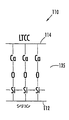
第2部材14はまた、図で形態を示したように、共にラミネートされる幾つかのLTCC層14a、14bを含むことが可能である。第2部材14はまた、図に示すように、実質的に廃熱を代表的に生成する絶縁ゲートバイポーラトランジスタ(IGBT:Insulated Gate Bipolar Transistor)又は他の集積回路等の、集積回路22を支える。第2部材はまた、図に示したワイヤ25を通って集積回路22の電気的接続24に接続される外部接続23を含むことが可能である。
【0006】
図2の拡大図に示すように、集積回路22は、第2部材14における受け側凹部27により支えられている。一連のマイクロ流体通路30は、冷却流体を供給するために集積回路22に隣接するLTCC部材14を通って供給されることが可能である。
【0007】
通常は、LTCC部材14とシリコン部材12は、図に示すように、接着層31により互いに接着される。一般に、熱可塑性及び/又は熱硬化性接着剤を用いる。また、金属層を用いることが可能である。残念ながら、接着層31は数々の問題点をもっている。一般に、接着層31は、シリコンとLTCCの間の界面において、完全な密封性を提供することはできない故に、冷却流体は損失することがあり得る。それに加えて、接着層31は、更にもう一つの熱を伝導する層としても機能することとなる。もちろん、一様であり、界面にはみ出さないか、そうでなければ、冷却流体の流れを遮断し、或いは制限するような接着層を提供することは困難かもしれない。換言すれば、そのような接着層31は、残念ながら、密封性が完全ではなく、一様ではない、部材との結合を提供するに過ぎない。
【0008】
Ohmanによる米国特許出願第5,443,890号明細書は、2つの隣接する部材間に形成されるマイクロ流体チャンネルのための漏れ防止シールを開示している。シーリング溝が提供され、それは、向かい合った部材の隣接する表面部分に対して押し付けられ、流体シーリング物質が満たされる。そのようなシーリング構造の提供には、付加的な製造工程が必要とされ、多くの応用に対して必ずしも適切とはいえない。
【0009】
(発明の概要)
上記背景技術に鑑みて、本発明の目的は、それ故、LTCCとシリコン部材とが互いに接合され、一様な接合を伴って気密封止を形成する方法及び関連する装置を提供することである。
【0010】
この目的及び他の目的、本発明にしたがった特徴及び優位性は、第1部材及び第2部材の対向表面が互いに接するように、第1部材及び第2部材を位置決めする段階から構成される電子装置の製造方法であって、第1部材はシリコンから構成され、第2部材は低温共焼成セラミック(LTCC)材料から構成される、方法により提供される。この方法はまた、密封封止を形成するために第1部材及び第2部材の対向表面を互いに陽極接合して接合する段階を含む。陽極接合による接合は、第1部材及び第2部材間の安全且つ一様な接合である。
【0011】
第1部材及び第2部材は、実質的に平面的な主要対向表面を有することが可能である。陽極接合による接合は、2つの異なる材料の熱膨張係数が異なることによって他の方法で生じ得る応力の影響を低減するために、これらの表面における一様な接合を提供する。
【0012】
陽極接合により接合する段階は、第1部材及び第2部材に亘って電圧を加える手順、第1部材及び第2部材の対向表面に圧力を加える手順、及び/又は第1部材及び第2部材を加熱する手順から構成される。この方法は又、第1部材及び第2部材の陽極接合による接合に先立った、第1部材及び第2部材の対向表面を清浄にする手順を含むことが可能である。
【0013】
この方法は、第1部材及び第2部材の少なくとも1つにおいて少なくとも1つの冷却構造を形成する手順を更に含むことが可能である。更に具体的には、少なくとも1つの冷却構造は、第1部材における少なくとも1つの第1マイクロ流体冷却構造と、少なくとも1つの第1マイクロ流体冷却構造と位置合わせされた第2部材における少なくとも1つの第2マイクロ流体冷却構造とから構成することが可能である。少なくとも1つの第1マイクロ流体冷却構造はエバポレータから構成されることが可能であり、少なくとも1つの第2マイクロ流体冷却構造は少なくとも1つのマイクロ流体通路から構成されることが可能である。陽極接合による接合は、その2つの部材間の気密封止を可能にし、他の方法では生じ得るその2つの部材間の界面における冷却流体の損失を低減するか、又はなくすことが可能である。
【0014】
この方法は、第2部材における少なくとも1つのマイクロ流体冷却通路に隣接するような、少なくとも1つの冷却構造に隣接する少なくとも1つの集積回路から構成される。前記少なくとも1つの集積回路は電気接続から構成されることが可能であり、第2部材は、少なくとも1つの集積回路の電気接続に接続される外部電気接続を支持することが可能である。
【0015】
代表的な電気装置のための陽極接合により接合する段階は、第1部材及び第2部材に亘って約500乃至1000Vの範囲内の電圧を印加する手順を含むことが可能である。同様に、陽極接合により接合する段階は、第1部材及び第2部材の対向表面に約1乃至20psiの範囲内の圧力を加える手順を含むことが可能である。このようなやり方に沿って、継続的に、陽極接合により接合する段階は、約100乃至150℃の範囲内の温度に第1部材及び第2部材を加熱する手順を含むことが可能である。
【0016】
本発明の他の特徴は、例えばマルチチップモジュール(MCM:Multi-Chip Module)又は他の類似するパッケージ集積回路のような電子装置に関連する。この電子装置は、シリコンから構成される第1部材と、低温共焼成セラミック(LTCC)材料から構成される第2部材とから構成される。更に、第1部材及び第2部材は、気密封止を形成するために共に陽極接合により接合される対向表面を有している。第1部材及び第2部材は、例えば、対向する略平面的な主要対向表面を有することが可能である。
【0017】
第1部材及び第2部材の少なくとも1つは少なくとも1つの冷却構造から構成されることが可能である。例えば、第1部材は、エバポレータのような、少なくとも1つの第1マイクロ流体冷却構造から構成されることが可能である。更に、第2部材は、第1部材の少なくとも1つの第1マイクロ流体冷却構造との位置合わせがなされた少なくとも1つの第2マイクロ流体冷却構造から構成されることが可能である。例えば、少なくとも1つの第2マイクロ流体冷却構造は、少なくとも1つのマイクロ流体通路から構成されることが可能である。
【0018】
電子装置はまた、第2部材の少なくとも1つの第2マイクロ流体冷却構造に隣接する少なくとも1つの集積回路を含むことが可能である。少なくとも1つの集積回路はまた、電気接続から構成されることが可能である。したがって、第2部材は、少なくとも1つの集積回路の電気接続に接続される外部電気接続から構成されることが可能である。
【0019】
(発明の詳細な説明)
本発明の好適な実施形態を示す添付の図を参照して、これから、本発明の実施形態について詳述することにする。しかしながら、本発明の実施形態は種々の異なる形態において実施することが可能であり、ここで述べる具体的に示す実施形態に限定すると解釈されるべきではない。正しくは、この開示が首尾一貫していて、当業者に本発明の主旨を十分に伝えることができるように、以下の実施形態について開示することとする。また、同様の符号は、一貫して同様の構成要素を示すこととする。
【0020】
はじめに、図3乃至7を参照しながら、本発明にしたがった電子装置及びその製造方法について説明する。特に、図3及び4に示すように、本発明にしたがった電子装置110の具体的な形態を示している。従来の接着層31が、ここで非常に詳細に述べるように、陽極接合により結合された海面135により置き換えられることにより、電子装置110は、図1及び2に示した先行技術の装置とは異なっている。
【0021】
電子装置110においては、図示したように、パッケージ111に単一の集積回路122が実装されているが、当業者は、本発明が他の電子装置に同様に適用可能であることを理解するであろう。例えば、その電子装置はMCM又は他の類似した装置であって、類似する実装パッケージに収容される1つ又はそれ以上の集積回路122を含む装置とすることも可能である。電子装置110は、図示したように、シリコンから構成される第1部材と、低温共焼成セラミック(LTCC:Low Temperature Co-fired Ceramic)材料から構成される第2部材とを含む。第1部材112及び第2部材114は、海面135において完全密封を形成するために、互いに陽極接合により接合される、向かい合う表面を有している。
【0022】
図で示した実施形態において、第1部材112及び第2部材114は、一般に、互いに陽極接合により接合される平面的な主要な対向表面を有している。第1部材112及び第2部材114のうち少なくとも1つは、当業者により評価されるであろう、少なくとも1つの冷却構造から構成されることが可能である。例えば、図に示した電子装置110のように、第1部材112は、図に示したエバポレータ116のような、少なくとも1つの第1マイクロ流体冷却構造を含む。
【0023】
第2部材114は、第1部材112の少なくとも1つの第1マイクロ流体冷却構造と位置合わせされた、少なくとも1つの第2マイクロ流体冷却構造を備えることが可能である。例えば、電子装置110の図に示した実施形態に置けるように、少なくとも1つの第2マイクロ流体冷却構造は、少なくとも1つのマイクロ流体通路130から構成されることが可能である。
【0024】
また、電子装置110は、図示したように、第2部材114のマイクロ流体通路130に隣接する集積回路122を含む。もちろん、他の実施形態においては、1つ以上の集積回路をパッケージ111に実装することが可能である。更に、光学/電子装置はまた、当業者に評価されるであろうように、以下に述べるが、実装且つ冷却されることが可能である。集積回路122はまた、図に示したように、そして当業者に評価されるであろうように、従来に技術を用いて、外部の電気接続123に引き出される電気接続124を備えている。
【0025】
当業者に評価されるであろうように、本発明の他の実施形態においては、集積回路122は、図示しないが、第2部材により支えられる外部の電気接続に接続される、バック接点層を備えることが可能である。更に、集積回路122は、他の実施形態において、フリップチップ接合を用いて、実装することが可能である。
【0026】
本発明の図示した電子装置110の他の要素は、図1及び2に示した電子装置の類似する要素と比較し易いように、符号の数字の増分を100として示している。更に、それらの共通要素は、ここで詳しく説明する必要はないと考える。
【0027】
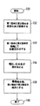
図5乃至7を参照して、本発明の実施形態にしたがった方法の特徴について、ここで更に特定して、詳細に説明することにする。この方法は、上記のように、電子装置110を製造するための方法である。図7のフローチャートに示すように、開始(ブロック150)から始まるこの方法は、ブロック152における、第1部材112及び第2部材114の対向表面を清浄及び調整する段階を含んでいる。調整は、各々の対向表面の表面粗さが所望の範囲内にあることを確実にするために、研磨又は他の技術を含むことが可能である。
【0028】
ブロック154において、この方法は、第1部材112及び第2部材114の研磨する手順を含んでおり、それ故、それらの対向表面は互いに接触可能である。上記のように、第1部材112はシリコンから構成され、第2部材はLTCC材料から構成されている。ブロック156において、第1部材112及び第2部材114の対向表面は、陽極接合を施されて互いに接合される。
【0029】
図5に図で示された装置を少し参照して、陽極接合による接合の実施形態について、更に説明する。第1部材112及び第2部材114は、装置140の上部電極142と下部電極141の間に位置合わせされることが可能である。下部電極141はまた、加熱サポート144により支持される。電源143を上部電極142及び株電極141に接続する。装置140は、第1部材112及び第2部材114の効果的な陽極接合による接合のために、必要な電圧、圧力及び温度範囲を提供することが可能である。
【0030】
図に示した電子装置110又はMCMのような代表的な電子装置のために、例えば、電源143は、第1部材112及び第2部材に亘って約500乃至1000Vの範囲内の電圧を供給することが可能である。同様に、この装置は、対向表面間の圧力が約1乃至20psiになるように、力を加えることが可能である。更に、加熱サポート144は、第1部材112及び第2部材114を、約100乃至150℃の範囲内の温度に加熱することが可能である。もちろん、本発明においては、他の電圧、圧力及び温度を検討し、当業者により評価されるであろうように、それらを他の装置のために用いることも可能である。陽極接合による接合(ブロック156)の後、接合された第1部材112及び第2部材114は清浄にされ、終了(ブロック160)の前に更に処理がなされる。
【0031】
上記のように、第1部材112及び第2部材114は、実質的に平面的な主要対向表面を有することが可能であり、それ故、陽極接合による接合は、2つのことなる材料の熱膨張係数の差により、他の方法では生じてしまうような応力の影響を低減することを可能にする、これらの表面における一様な接合を提供する。陽極接合による接合は、第1部材112及び第2部材114間の安全且つ一様な完全密封を提供し、他方、上記の、接着剤を用いることによりもたらされる不都合を克服することができる。
【0032】
この方法は、更に、第1部材112及び第2部材114の少なくとも1つにおいて、少なくとも1つの冷却構造を形成する手順を含むことが可能である。これらの冷却構造は、陽極接合による接合の前又は後に形成することが可能であり、或いは、それらの両方を陽極接合による接合の前又は後に形成することが可能である。この方法はまた、少なくとも1つの冷却構造に隣接する、即ち、第2部材4又はLTCC部材114における少なくとも1つのマイクロ流体冷却通路130に隣接する、少なくとも1つの集積回路122を位置決めする手順を含むことが可能である。
【0033】
陽極接合による接合は、2つの第1部材112及び第2部材114間の完全密封を好適に提供し、他の方法では生じてしまう2つの第1部材112及び第2部材114間の界面における冷却流体損失を著しく低減する又はなくすことができる。図6に図示するものが最も好適と考えられるが、陽極接合による接合は、第1部材112と第2部材の間の界面135において配位共有マトリクスの形成をもたらすものと考えられる。
【0034】
上記の詳細説明及び関連する図で開示した本発明が教示する特徴により、本発明について多くの修正及び変形が可能であることは、当業者には容易に理解されるであろう。したがって、本発明は開示された実施形態に限定されるものではなく、そのような他の修正及び実施形態は、本発明の請求項における主旨及び適用範囲に含むものと考える。
【図面の簡単な説明】
【図1】 先行技術にしたがった電子装置の模式的な断面図である。
【図2】 図1に示した電子装置の一部を拡大して示す図である。
【図3】 本発明にしたがった電子装置の模式的な断面図
【図4】 図3に示した電子装置の一部を拡大して示す図である。
【図5】 本発明にしたがった装置において製造された、図3に示すような電子装置の模式図である。
【図6】 図3に示す電子装置におけるような陽極接合により接合された界面の模式図である。
【図7】 本発明にしたがった方法を示すフローチャートである。[0001]
(Technical field)
The present invention relates to the field of electronic devices and manufacturing methods, and more particularly to such devices and manufacturing methods including integrated circuit packages.
[0002]
(Background technology)
Integrated circuits are widely used in many types of electronic devices. The integrated circuit includes a silicon substrate on which many active elements such as transistors are formed. Also, it is usually required to support one or more such integrated circuits and is housed in a package to allow protection and external electrical connections.
[0003]
In typical integrated circuits, as the density of active devices increases, the resulting heat loss becomes increasingly significant. Designers have developed cooling techniques for integrated circuits based on micro-electrochemical (MEM) technology.
[0004]
For example, as shown in FIG. 1, a prior art
[0005]
The second member 14 can also include
[0006]
As shown in the enlarged view of FIG. 2, the integrated
[0007]
Normally, the LTCC member 14 and the
[0008]
US Patent Application No. 5,443,890 to Ohman discloses a leak-proof seal for a microfluidic channel formed between two adjacent members. A sealing groove is provided that is pressed against an adjacent surface portion of the opposing member to fill the fluid sealing material. Providing such a sealing structure requires additional manufacturing steps and is not necessarily appropriate for many applications.
[0009]
(Summary of Invention)
In view of the above background art, it is therefore an object of the present invention to provide a method and related apparatus in which an LTCC and a silicon member are bonded together to form a hermetic seal with uniform bonding. .
[0010]
This and other objects, features and advantages in accordance with the present invention include an electronic component comprising positioning the first member and the second member such that the opposing surfaces of the first member and the second member are in contact with each other. A method of manufacturing an apparatus is provided by a method in which a first member is composed of silicon and a second member is composed of a low temperature co-fired ceramic (LTCC) material. The method also includes anodically bonding the opposing surfaces of the first member and the second member to each other to form a hermetic seal. The anodic bonding is a safe and uniform bonding between the first member and the second member.
[0011]
The first member and the second member can have a substantially planar main opposing surface. Anodic bonding provides a uniform bond at these surfaces to reduce the effects of stresses that may otherwise be caused by the different coefficients of thermal expansion of two different materials.
[0012]
The step of joining by anodic bonding includes a step of applying a voltage across the first member and the second member, a step of applying pressure to the opposing surfaces of the first member and the second member, and / or the first member and the second member. It consists of a heating procedure. The method can also include a step of cleaning the opposing surfaces of the first member and the second member prior to the anodic bonding of the first member and the second member.
[0013]
The method may further include the step of forming at least one cooling structure in at least one of the first member and the second member. More specifically, the at least one cooling structure includes at least one first microfluidic cooling structure in the first member and at least one first in the second member aligned with the at least one first microfluidic cooling structure. 2 microfluidic cooling structure. At least one first microfluidic cooling structure can be composed of an evaporator, and at least one second microfluidic cooling structure can be composed of at least one microfluidic passage. Bonding by anodic bonding allows a hermetic seal between the two members and can reduce or eliminate the loss of cooling fluid at the interface between the two members that may otherwise occur.
[0014]
The method consists of at least one integrated circuit adjacent to at least one cooling structure, such as adjacent to at least one microfluidic cooling passage in the second member. The at least one integrated circuit may comprise an electrical connection, and the second member may support an external electrical connection that is connected to the electrical connection of the at least one integrated circuit.
[0015]
Bonding by anodic bonding for a typical electrical device can include applying a voltage in the range of about 500 to 1000 V across the first member and the second member. Similarly, joining by anodic bonding can include applying a pressure in the range of about 1 to 20 psi to the opposing surfaces of the first member and the second member. Consistent with such a manner, the step of joining by anodic bonding can include a procedure of heating the first member and the second member to a temperature in the range of about 100 to 150 ° C.
[0016]
Another aspect of the present invention relates to electronic devices such as multi-chip modules (MCMs) or other similar packaged integrated circuits. The electronic device includes a first member made of silicon and a second member made of a low temperature co-fired ceramic (LTCC) material. Furthermore, the first member and the second member have opposing surfaces that are joined together by anodic bonding to form a hermetic seal. The first member and the second member can have, for example, opposing substantially planar main opposing surfaces.
[0017]
At least one of the first member and the second member can be composed of at least one cooling structure. For example, the first member can be composed of at least one first microfluidic cooling structure, such as an evaporator. Further, the second member can comprise at least one second microfluidic cooling structure that is aligned with at least one first microfluidic cooling structure of the first member. For example, the at least one second microfluidic cooling structure can be comprised of at least one microfluidic passage.
[0018]
The electronic device can also include at least one integrated circuit adjacent to the at least one second microfluidic cooling structure of the second member. The at least one integrated circuit can also consist of electrical connections. Thus, the second member can consist of an external electrical connection connected to the electrical connection of at least one integrated circuit.
[0019]
(Detailed description of the invention)
Reference will now be made in detail to embodiments of the present invention, examples of which are illustrated in the accompanying drawings that illustrate preferred embodiments of the present invention. However, embodiments of the invention may be implemented in a variety of different forms and should not be construed as limited to the specific embodiments set forth herein. Rather, the following embodiments are disclosed so that this disclosure is consistent and can fully convey the gist of the present invention to those skilled in the art. Moreover, the same code | symbol shall show the same component consistently.
[0020]
First, an electronic device and a manufacturing method thereof according to the present invention will be described with reference to FIGS. In particular, as shown in FIGS. 3 and 4, a specific form of
[0021]
In the
[0022]
In the illustrated embodiment, the
[0023]
The
[0024]
The
[0025]
As will be appreciated by those skilled in the art, in other embodiments of the present invention, integrated
[0026]
Other elements of the illustrated
[0027]
With reference to FIGS. 5 to 7, the features of the method according to embodiments of the present invention will now be further identified and described in detail. This method is a method for manufacturing the
[0028]
In block 154, the method includes a procedure for polishing the
[0029]
With reference to the apparatus shown in FIG. 5 for a while, an embodiment of bonding by anodic bonding will be further described. The
[0030]
For exemplary electronic devices such as the
[0031]
As described above, the
[0032]
The method may further include the step of forming at least one cooling structure in at least one of the
[0033]
Bonding by anodic bonding preferably provides a complete seal between the two
[0034]
It will be readily appreciated by those skilled in the art that many modifications and variations of the present invention are possible in light of the features taught by the invention disclosed in the foregoing detailed description and the associated figures. Accordingly, the present invention is not limited to the disclosed embodiments, and other such modifications and embodiments are considered within the spirit and scope of the claims of the present invention.
[Brief description of the drawings]
FIG. 1 is a schematic cross-sectional view of an electronic device according to the prior art.
2 is an enlarged view showing a part of the electronic device shown in FIG. 1;
3 is a schematic cross-sectional view of an electronic device according to the present invention. FIG. 4 is an enlarged view of a part of the electronic device shown in FIG.
5 is a schematic diagram of an electronic device as shown in FIG. 3 manufactured in a device according to the present invention.
6 is a schematic view of an interface bonded by anodic bonding as in the electronic device shown in FIG. 3;
FIG. 7 is a flow chart illustrating a method according to the present invention.
Claims (3)
第1部材及び第2部材は、第1マイクロ流体冷却構造及び第2マイクロ流体冷却構造のそれぞれを別個に有し、
前記第1部材及び前記第2部材のそれぞれの対向する面は互いに接し、前記第1マイクロ流体冷却構造及び前記第2マイクロ流体冷却構造の両方についての陽極接合により前記第1部材及び前記第2部材は前記第1マイクロ流体冷却構造と前記第2マイクロ流体冷却構造との間に形成される連通部分を有し、
前記第1部材は、シリコンから構成され、エバポレータを有する少なくとも1つの第1マイクロ流体冷却構造を有し、
前記第2部材は、低温共焼成セラミック(LTCC)材料から構成され、前記第1部材の前記少なくとも1つの第1マイクロ流体冷却構造と位置合わせされ且つ集積回路に隣接して備えられる、マイクロ流体冷却通路が形成される少なくとも1つの第2マイクロ流体冷却構造を有する、
ように、前記第1部材及び前記第2部材を位置決めする段階;並びに
前記第1部材と前記第2部材との間に気密封止部分を形成するように、前記第1部材及び前記第2部材の前記それぞれの対向する面を共に陽極接合により接合する段階;
を有することを特徴とする方法。A method of manufacturing an electronic device comprising:
The first member and the second member each have a first microfluidic cooling structure and a second microfluidic cooling structure separately,
The opposing surfaces of the first member and the second member are in contact with each other, and the first member and the second member are subjected to anodic bonding for both the first microfluidic cooling structure and the second microfluidic cooling structure. Has a communicating portion formed between the first microfluidic cooling structure and the second microfluidic cooling structure,
Wherein the first member is composed of silicon, having at least one first microfluidic cooling structure having an evaporator,
Said second member is composed of a low temperature co-fired ceramic (LTCC) material, it is provided adjacent to the at least one first microfluidic cooling structure and aligned and integrated circuit of the first member, the microfluidic cooling Having at least one second microfluidic cooling structure in which a passage is formed;
Positioning the first member and the second member; and forming a hermetic sealing portion between the first member and the second member. Joining the respective opposing surfaces together by anodic bonding;
A method characterized by comprising:
前記少なくとも1つの第2マイクロ流体冷却構造に隣接する少なくとも1つの集積回路;
を有する電子装置であって:
第1部材及び第2部材は、第1マイクロ流体冷却構造及び第2マイクロ流体冷却構造のそれぞれを別個に有し、
前記第1部材及び前記第2部材のそれぞれの対向する面は互いに接し、前記第1マイクロ流体冷却構造及び前記第2マイクロ流体冷却構造の両方についての陽極接合により前記第1部材及び前記第2部材は前記第1マイクロ流体冷却構造と前記第2マイクロ流体冷却構造との間に形成される連通部分を有する、
ように、前記第1部材及び前記第2部材は位置決めされる;
ことを特徴とする電子装置。A first member composed of silicon and having at least one first microfluidic cooling structure with an evaporator; composed of a low temperature co-fired ceramic (LTCC) material, and the at least one first microfluidic cooling of the first member A second member having at least one second microfluidic cooling structure in alignment with the structure and provided adjacent to the integrated circuit in which a microfluidic cooling passage is formed; and the at least one second microfluidic cooling structure At least one integrated circuit adjacent to;
An electronic device having:
The first member and the second member each have a first microfluidic cooling structure and a second microfluidic cooling structure separately,
The opposing surfaces of the first member and the second member are in contact with each other, and the first member and the second member are subjected to anodic bonding for both the first microfluidic cooling structure and the second microfluidic cooling structure. Has a communication portion formed between the first microfluidic cooling structure and the second microfluidic cooling structure,
As such, the first member and the second member are positioned;
An electronic device characterized by that.
Applications Claiming Priority (2)
| Application Number | Priority Date | Filing Date | Title |
|---|---|---|---|
| US09/741,754 US6809424B2 (en) | 2000-12-19 | 2000-12-19 | Method for making electronic devices including silicon and LTCC and devices produced thereby |
| PCT/US2001/046775 WO2002050888A2 (en) | 2000-12-19 | 2001-12-10 | Method for making electronic devices including silicon and ltcc |
Publications (3)
| Publication Number | Publication Date |
|---|---|
| JP2004537156A JP2004537156A (en) | 2004-12-09 |
| JP2004537156A5 JP2004537156A5 (en) | 2005-04-28 |
| JP4454226B2 true JP4454226B2 (en) | 2010-04-21 |
Family
ID=24982035
Family Applications (1)
| Application Number | Title | Priority Date | Filing Date |
|---|---|---|---|
| JP2002551895A Expired - Fee Related JP4454226B2 (en) | 2000-12-19 | 2001-12-10 | Method of manufacturing electronic device including silicon and LTCC, and electronic device manufactured thereby |
Country Status (7)
| Country | Link |
|---|---|
| US (2) | US6809424B2 (en) |
| EP (1) | EP1362368A2 (en) |
| JP (1) | JP4454226B2 (en) |
| KR (1) | KR100574582B1 (en) |
| CN (1) | CN1494739A (en) |
| AU (1) | AU2002225952A1 (en) |
| WO (1) | WO2002050888A2 (en) |
Families Citing this family (19)
| Publication number | Priority date | Publication date | Assignee | Title |
|---|---|---|---|---|
| US6976527B2 (en) * | 2001-07-17 | 2005-12-20 | The Regents Of The University Of California | MEMS microcapillary pumped loop for chip-level temperature control |
| JP3896840B2 (en) * | 2001-12-13 | 2007-03-22 | ソニー株式会社 | COOLING DEVICE, ELECTRONIC DEVICE DEVICE, AND COOLING DEVICE MANUFACTURING METHOD |
| US6741469B1 (en) * | 2003-02-07 | 2004-05-25 | Sun Microsystems, Inc. | Refrigeration cooling assisted MEMS-based micro-channel cooling system |
| WO2005006436A1 (en) * | 2003-07-08 | 2005-01-20 | Infineon Technologies Ag | Integrated coolant circuit arrangement, operating method and production method |
| US7199437B2 (en) * | 2004-01-20 | 2007-04-03 | Harris Corporation | Fabrication process for embedding optical band gap structures in a low temperature co-fired ceramic substrate |
| US7115182B2 (en) * | 2004-06-15 | 2006-10-03 | Agency For Science, Technology And Research | Anodic bonding process for ceramics |
| JP4375186B2 (en) * | 2004-09-30 | 2009-12-02 | 株式会社日立製作所 | Electronic device using anodic bonding structure |
| US7691723B2 (en) | 2005-01-07 | 2010-04-06 | Honeywell International Inc. | Bonding system having stress control |
| JP4740926B2 (en) | 2007-11-27 | 2011-08-03 | フェリカネットワークス株式会社 | Service providing system, service providing server, and information terminal device |
| US7622786B2 (en) * | 2007-12-28 | 2009-11-24 | Aptina Imaging Corporation | EMI shielding for imager devices |
| DE102008014619C5 (en) * | 2008-03-17 | 2015-06-25 | Friedrich-Schiller-Universität Jena | Adaptive mirror and method for its production |
| JP5175650B2 (en) * | 2008-08-06 | 2013-04-03 | ニッコー株式会社 | Porcelain capable of anodic bonding and composition for porcelain |
| JP5130151B2 (en) * | 2008-08-26 | 2013-01-30 | パナソニック株式会社 | Capacitive semiconductor physical quantity sensor manufacturing method and capacitive semiconductor physical quantity sensor |
| ATE554361T1 (en) * | 2009-04-28 | 2012-05-15 | Abb Research Ltd | HEAT PIPE WITH TWISTED TUBE |
| EP2246654B1 (en) * | 2009-04-29 | 2013-12-11 | ABB Research Ltd. | Multi-row thermosyphon heat exchanger |
| EP2328172B1 (en) * | 2009-10-02 | 2019-06-26 | Abb Research Ltd. | A power-electronic arrangement |
| US8179676B2 (en) * | 2010-07-21 | 2012-05-15 | Telefonaktiebolaget L M Ericsson (Publ) | Optical interconnects in cooling substrates |
| CN102815665A (en) * | 2011-06-07 | 2012-12-12 | 北京大学 | Interface method of micro-fluidic pipeline embedded in low-temperature co-fired ceramic substrate |
| KR101255935B1 (en) * | 2011-07-08 | 2013-04-23 | 삼성전기주식회사 | Power Module Package and Method for Manufacturing the same |
Family Cites Families (32)
| Publication number | Priority date | Publication date | Assignee | Title |
|---|---|---|---|---|
| US3540957A (en) | 1966-10-05 | 1970-11-17 | Texas Instruments Inc | Ceramic bonding |
| US3783218A (en) | 1972-01-12 | 1974-01-01 | Gen Electric | Electrostatic bonding process |
| JPS54131892A (en) | 1978-04-05 | 1979-10-13 | Hitachi Ltd | Semiconductor pressure converter |
| US4573067A (en) * | 1981-03-02 | 1986-02-25 | The Board Of Trustees Of The Leland Stanford Junior University | Method and means for improved heat removal in compact semiconductor integrated circuits |
| US4481497A (en) | 1982-10-27 | 1984-11-06 | Kulite Semiconductor Products, Inc. | Transducer structures employing ceramic substrates and diaphragms |
| US4452624A (en) | 1982-12-21 | 1984-06-05 | The United States Of America As Represented By The Secretary Of The Navy | Method for bonding insulator to insulator |
| EP0161740B1 (en) | 1984-05-09 | 1991-06-12 | Kabushiki Kaisha Toshiba | Method of manufacturing semiconductor substrate |
| SE9100392D0 (en) | 1991-02-08 | 1991-02-08 | Pharmacia Biosensor Ab | A METHOD OF PRODUCING A SEALING MEANS IN A MICROFLUIDIC STRUCTURE AND A MICROFLUIDIC STRUCTURE COMPRISING SUCH SEALING MEANS |
| DE69211074T2 (en) * | 1991-08-26 | 1996-10-02 | Sun Microsystems Inc | Process and apparatus for cooling multi-chip modules using the complete heat pipe technology |
| EP0539741B1 (en) | 1991-09-30 | 2003-01-15 | Canon Kabushiki Kaisha | Anodic bonding process with light irradiation |
| JPH05169666A (en) | 1991-12-25 | 1993-07-09 | Rohm Co Ltd | Manufacturing ink jet print head |
| US5318820A (en) * | 1992-09-24 | 1994-06-07 | Hughes Aircraft Company | HTCC/LTCC use of multiple ceramic tapes in high rate production |
| JP2533272B2 (en) | 1992-11-17 | 1996-09-11 | 住友電気工業株式会社 | Method for manufacturing semiconductor device |
| DE4311762C2 (en) | 1993-04-08 | 1995-02-02 | Josef Dr Kemmer | Method of connecting electrical contact points |
| US5493305A (en) | 1993-04-15 | 1996-02-20 | Hughes Aircraft Company | Small manufacturable array lattice layers |
| US5455385A (en) | 1993-06-28 | 1995-10-03 | Harris Corporation | Multilayer LTCC tub architecture for hermetically sealing semiconductor die, external electrical access for which is provided by way of sidewall recesses |
| DE69434104T2 (en) | 1993-08-09 | 2005-11-03 | Nippon Telegraph And Telephone Corp. | Opto-electronic hybrid integration platform and optical sub-module |
| EP0658937A1 (en) | 1993-12-08 | 1995-06-21 | Hughes Aircraft Company | Vertical IC chip stack with discrete chip carriers formed from dielectric tape |
| DE4408352C2 (en) * | 1994-03-12 | 1996-02-08 | Meinhard Prof Dr Knoll | Miniaturized substance-recognizing flow sensor and method for its production |
| US5585069A (en) | 1994-11-10 | 1996-12-17 | David Sarnoff Research Center, Inc. | Partitioned microelectronic and fluidic device array for clinical diagnostics and chemical synthesis |
| US5591679A (en) | 1995-04-12 | 1997-01-07 | Sensonor A/S | Sealed cavity arrangement method |
| JP3160796B2 (en) | 1995-05-30 | 2001-04-25 | 株式会社日立製作所 | Semiconductor pressure detector |
| US5611541A (en) * | 1995-08-24 | 1997-03-18 | Paino; Robert | Method of playing a ball game |
| JP3292798B2 (en) * | 1995-10-04 | 2002-06-17 | 三菱電機株式会社 | Semiconductor device |
| US5892279A (en) * | 1995-12-11 | 1999-04-06 | Northrop Grumman Corporation | Packaging for electronic power devices and applications using the packaging |
| JP3079983B2 (en) * | 1995-12-26 | 2000-08-21 | 株式会社日立製作所 | Semiconductor combustion pressure sensor |
| US5866469A (en) | 1996-06-13 | 1999-02-02 | Boeing North American, Inc. | Method of anodic wafer bonding |
| US5801442A (en) * | 1996-07-22 | 1998-09-01 | Northrop Grumman Corporation | Microchannel cooling of high power semiconductor devices |
| US6091146A (en) | 1997-12-09 | 2000-07-18 | Trw Inc. | Ceramic lid for large multi-chip modules |
| WO2001029890A2 (en) * | 1999-10-19 | 2001-04-26 | Imego Ab | Method relating to anodic bonding |
| US6232151B1 (en) * | 1999-11-01 | 2001-05-15 | General Electric Company | Power electronic module packaging |
| US6462410B1 (en) * | 2000-08-17 | 2002-10-08 | Sun Microsystems Inc | Integrated circuit component temperature gradient reducer |
-
2000
- 2000-12-19 US US09/741,754 patent/US6809424B2/en not_active Expired - Lifetime
-
2001
- 2001-12-10 CN CNA018221300A patent/CN1494739A/en active Pending
- 2001-12-10 WO PCT/US2001/046775 patent/WO2002050888A2/en active IP Right Grant
- 2001-12-10 JP JP2002551895A patent/JP4454226B2/en not_active Expired - Fee Related
- 2001-12-10 AU AU2002225952A patent/AU2002225952A1/en not_active Abandoned
- 2001-12-10 EP EP01995388A patent/EP1362368A2/en not_active Withdrawn
- 2001-12-10 KR KR1020037008195A patent/KR100574582B1/en active IP Right Grant
-
2004
- 2004-08-19 US US10/921,511 patent/US6987033B2/en not_active Expired - Lifetime
Also Published As
| Publication number | Publication date |
|---|---|
| US20020130408A1 (en) | 2002-09-19 |
| WO2002050888A2 (en) | 2002-06-27 |
| KR20040064602A (en) | 2004-07-19 |
| US20050019986A1 (en) | 2005-01-27 |
| CN1494739A (en) | 2004-05-05 |
| AU2002225952A1 (en) | 2002-07-01 |
| WO2002050888A3 (en) | 2003-08-07 |
| KR100574582B1 (en) | 2006-04-28 |
| JP2004537156A (en) | 2004-12-09 |
| US6987033B2 (en) | 2006-01-17 |
| US6809424B2 (en) | 2004-10-26 |
| EP1362368A2 (en) | 2003-11-19 |
Similar Documents
| Publication | Publication Date | Title |
|---|---|---|
| JP4454226B2 (en) | Method of manufacturing electronic device including silicon and LTCC, and electronic device manufactured thereby | |
| US6528878B1 (en) | Device for sealing and cooling multi-chip modules | |
| JP7021854B2 (en) | Electronic circuit package for electric power and its manufacturing method | |
| US10971430B2 (en) | Semiconductor device | |
| JP7482259B2 (en) | Power Semiconductor Modules | |
| US20230037380A1 (en) | Direct Liquid Cooling With O-Ring Sealing | |
| US20200312740A1 (en) | Low thermal resistance power module packaging | |
| JP7204919B2 (en) | Power module and manufacturing method thereof | |
| CN114097076A (en) | Semiconductor package, electronic device, and method for manufacturing semiconductor package | |
| CN105280564B (en) | Carrier, semiconductor module and preparation method thereof | |
| US6727585B2 (en) | Power device with a plastic molded package and direct bonded substrate | |
| JP7072624B1 (en) | Power semiconductor devices and methods for manufacturing power semiconductor devices | |
| US20240203817A1 (en) | Semiconductor apparatus, and manufacturing method therefor | |
| JP7482833B2 (en) | Semiconductor device and method for manufacturing the same | |
| US9812378B2 (en) | Packaging for high power integrated circuits and infrared emitter arrays | |
| TW202310245A (en) | Electronic assemblies with thermal interface structure | |
| JP2531125B2 (en) | IC chip carrier module | |
| JP2002134799A (en) | Silicon substrate, manufacturing method therefor, thermoelectric module, and semiconductor laser device | |
| JPH01293636A (en) | Airtight sealing chip carrier | |
| JPH01272140A (en) | Semiconductor device | |
| JPH04303950A (en) | Base plate for mounting semiconductor | |
| JPS62281452A (en) | Semiconductor module | |
| JP2005229058A (en) | Semiconductor device | |
| JPH05251599A (en) | Semiconductor chip module and its manufacture |
Legal Events
| Date | Code | Title | Description |
|---|---|---|---|
| A977 | Report on retrieval |
Free format text: JAPANESE INTERMEDIATE CODE: A971007 Effective date: 20060216 |
|
| A131 | Notification of reasons for refusal |
Free format text: JAPANESE INTERMEDIATE CODE: A131 Effective date: 20060228 |
|
| A601 | Written request for extension of time |
Free format text: JAPANESE INTERMEDIATE CODE: A601 Effective date: 20060525 |
|
| A602 | Written permission of extension of time |
Free format text: JAPANESE INTERMEDIATE CODE: A602 Effective date: 20060601 |
|
| A521 | Request for written amendment filed |
Free format text: JAPANESE INTERMEDIATE CODE: A523 Effective date: 20060823 |
|
| A02 | Decision of refusal |
Free format text: JAPANESE INTERMEDIATE CODE: A02 Effective date: 20061017 |
|
| A521 | Request for written amendment filed |
Free format text: JAPANESE INTERMEDIATE CODE: A523 Effective date: 20070115 |
|
| A911 | Transfer to examiner for re-examination before appeal (zenchi) |
Free format text: JAPANESE INTERMEDIATE CODE: A911 Effective date: 20070312 |
|
| A912 | Re-examination (zenchi) completed and case transferred to appeal board |
Free format text: JAPANESE INTERMEDIATE CODE: A912 Effective date: 20070406 |
|
| A521 | Request for written amendment filed |
Free format text: JAPANESE INTERMEDIATE CODE: A523 Effective date: 20090427 |
|
| A521 | Request for written amendment filed |
Free format text: JAPANESE INTERMEDIATE CODE: A523 Effective date: 20090817 |
|
| A521 | Request for written amendment filed |
Free format text: JAPANESE INTERMEDIATE CODE: A523 Effective date: 20091124 |
|
| A521 | Request for written amendment filed |
Free format text: JAPANESE INTERMEDIATE CODE: A523 Effective date: 20091124 |
|
| A521 | Request for written amendment filed |
Free format text: JAPANESE INTERMEDIATE CODE: A523 Effective date: 20090817 |
|
| A521 | Request for written amendment filed |
Free format text: JAPANESE INTERMEDIATE CODE: A523 Effective date: 20090427 |
|
| A01 | Written decision to grant a patent or to grant a registration (utility model) |
Free format text: JAPANESE INTERMEDIATE CODE: A01 |
|
| A61 | First payment of annual fees (during grant procedure) |
Free format text: JAPANESE INTERMEDIATE CODE: A61 Effective date: 20100202 |
|
| FPAY | Renewal fee payment (event date is renewal date of database) |
Free format text: PAYMENT UNTIL: 20130212 Year of fee payment: 3 |
|
| R150 | Certificate of patent or registration of utility model |
Free format text: JAPANESE INTERMEDIATE CODE: R150 |
|
| FPAY | Renewal fee payment (event date is renewal date of database) |
Free format text: PAYMENT UNTIL: 20140212 Year of fee payment: 4 |
|
| R250 | Receipt of annual fees |
Free format text: JAPANESE INTERMEDIATE CODE: R250 |
|
| R250 | Receipt of annual fees |
Free format text: JAPANESE INTERMEDIATE CODE: R250 |
|
| LAPS | Cancellation because of no payment of annual fees |