以下に、本発明の処理装置の一実施の形態の構成について図面を参照して説明する。本実施の形態では、略平板状(ディスク状)の着脱可能な被処理物としてディスク状記録媒体である光ディスクに情報を記録および読み出す処理装置としてのディスク装置を例示して説明するが、情報の読み出しあるいは記録のみでもよい。さらには、記録媒体に限らず、MD(Mini DisC)などのようにケース内にディスク状記録媒体が収容されたもの、鋼板など、いずれのものも対象とすることができる。なお、ディスク状記録媒体としては、光ディスクに限らず、磁気ディスク、光磁気ディスクなどの、いずれのディスク状記録媒体を対象とすることができる。また、ドライブ装置として、回転する光ディスクの記録面に沿って略径方向で光ピックアップを移動させる構成に限らず、例えば光ディスクを回転させずに記録面に沿って光ピックアップを移動させて、記録処理や読取処理を実施する構成などとしてもよい。
The configuration of an embodiment of the processing apparatus of the present invention will be described below with reference to the drawings. In the present embodiment, a disk device as a processing device for recording and reading information on and reading information from and on an optical disk, which is a disk-shaped recording medium, will be described as an example of a substantially flat (disc-shaped) removable object. Only reading or recording may be used. Furthermore, not only the recording medium, but also a disk-shaped recording medium housed in a case, such as MD (Mini Disc C), or a steel plate can be used. The disk-shaped recording medium is not limited to the optical disk, and any disk-shaped recording medium such as a magnetic disk or a magneto-optical disk can be used. Further, the drive device is not limited to the configuration in which the optical pickup is moved in a substantially radial direction along the recording surface of the rotating optical disc. For example, the optical pickup is moved along the recording surface without rotating the optical disc. Or a configuration for performing a reading process.
〔ディスク装置の構成〕
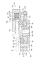
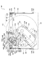
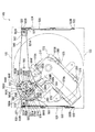
図1は、ディスク装置の概略構成を示す斜視図である。図2は、ディスク装置内部の概略構成を示す平面図である。図3は、下側筐体を上面側から見た平面図である。図4は、下側筐体の左側板部近傍の概略構成を示す断面図である。図5は、下側筐体を下面側から見た平面図である。図6は、ディスク装置内部のディスク保持機構および退避制御機構を取り外した状態の概略構成を示す平面図である。図7は、ディスク保持機構および退避制御機構の概略構成を示す平面図である。図8は、搬送手段の概略構成を示す部分断面図である。図9は、搬送基部の概略構成を示す図であり、(A)は平面図、(B)は側面図である。図10は、押圧手段の概略構成を示す図であり、(A)は平面図、(B)は側面図である。図11は、台座保持部の保持部を模式的に示す断面図である。図12は、駆動部の概略構成を示す平面図である。
[Disk device configuration]
FIG. 1 is a perspective view showing a schematic configuration of the disk device. FIG. 2 is a plan view showing a schematic configuration inside the disk device. FIG. 3 is a plan view of the lower housing as viewed from the upper surface side. FIG. 4 is a cross-sectional view showing a schematic configuration in the vicinity of the left side plate portion of the lower housing. FIG. 5 is a plan view of the lower housing as viewed from the lower surface side. FIG. 6 is a plan view showing a schematic configuration in a state where the disk holding mechanism and the retraction control mechanism inside the disk device are removed. FIG. 7 is a plan view showing a schematic configuration of the disk holding mechanism and the retraction control mechanism. FIG. 8 is a partial cross-sectional view showing a schematic configuration of the conveying means. FIG. 9 is a diagram showing a schematic configuration of the transport base, where (A) is a plan view and (B) is a side view. FIG. 10 is a diagram showing a schematic configuration of the pressing means, where (A) is a plan view and (B) is a side view. FIG. 11 is a cross-sectional view schematically showing the holding portion of the pedestal holding portion. FIG. 12 is a plan view showing a schematic configuration of the drive unit.
図1において、100はディスク装置で、このディスク装置100は、例えば車両などの移動体に搭載されるものである。このディスク装置100は、着脱可能に装着される略平板状である円板状の光ディスク1N(Nは1または2)に記録された情報を再生する再生処理、および、光ディスク1Nに情報を記録する記録処理を実施する。また、ディスク装置100は、例えば被処理物、および第1のディスク状記録媒体としての光ディスク11の再生中(以下、光ディスク11を再生ディスク11と適宜称す)に第2のディスク状記録媒体としての光ディスク12が挿入されると(以下、光ディスク12を交換ディスク12と適宜称す)、再生ディスク11を交換ディスク12に自動的に交換する。そして、ディスク装置100は、例えば金属製で内部空間を有する略四角箱状のケース体110を有している。
In FIG. 1, reference numeral 100 denotes a disk device, which is mounted on a moving body such as a vehicle. The disc device 100 reproduces information recorded on a disc-shaped optical disc 1N (N is 1 or 2) that is a substantially flat plate that is detachably mounted, and records information on the optical disc 1N. Perform the recording process. In addition, the disk device 100 can be used as a second disk-shaped recording medium, for example, during the reproduction of an object to be processed and the optical disk 11 as a first disk-shaped recording medium (hereinafter, the optical disk 11 is appropriately referred to as the reproduction disk 11). When the optical disk 12 is inserted (hereinafter, the optical disk 12 is appropriately referred to as a replacement disk 12), the playback disk 11 is automatically replaced with the replacement disk 12. The disk device 100 includes a substantially square box-shaped case body 110 made of, for example, metal and having an internal space.
ケース体110は、上面を開口する金属製の下側筐体120と、この下側筐体120の上面を閉塞する金属製の上側筐体130と、下側筐体120および上側筐体130の正面側に設けられる合成樹脂にて細長板状に形成された化粧板111と、を備えている。そして、化粧板111には、光ディスク1Nが挿通可能な長手方向に沿った細長スリット状の挿通口としてのディスク挿通口111Aが開口形成されている。また、ケース体110の化粧板111には、ケース体110内に挿入された再生ディスク11を排出する際に操作されるイジェクトボタン111Bなど、ディスク装置100全体の動作を設定するための図示しない各種操作ボタンや処理状態を表示により報知する表示パネルなどが適宜設けられている。
The case body 110 includes a metal lower housing 120 having an upper surface opened, a metal upper housing 130 that closes the upper surface of the lower housing 120, and the lower housing 120 and the upper housing 130. And a decorative board 111 formed in a long and thin plate shape with a synthetic resin provided on the front side. The decorative plate 111 is formed with a disc insertion port 111A as an elongated slit-shaped insertion port along the longitudinal direction through which the optical disc 1N can be inserted. In addition, the decorative plate 111 of the case body 110 includes various types (not shown) for setting the overall operation of the disk device 100, such as an eject button 111B that is operated when the playback disk 11 inserted into the case body 110 is ejected. An operation button and a display panel for notifying the processing state by display are appropriately provided.
下側筐体120は、図2に示すように、長方形平板状の底板部121を有している。この底板部121の短手方向の一側縁、すなわち底板部121の前面側には、前面板部122が略垂直に折曲形成されている。この前面板部122には、ディスク挿通口111Aに対応する図示しないスリット状の挿通孔が設けられ、化粧板111が取り付けられる。また、底板部121の短手方向の他側縁、すなわち底板部121の後面側には、前面板部122と同方向に略垂直に折曲されて前面板部122と対向する後面板部123が形成されている。さらに、底板部121の長手方向の一側縁には、略垂直に折曲された右側板部124が形成されている。この右側板部124は、前面板部122および後面板部123に略直交し、前面板部122から後面板部123に向かう前後方向が長手となるように形成されている。また、底板部121の長手方向の他側縁には、略垂直に折曲され、右側板部124と対向する左側板部125が形成されている。この左側板部125も、右側板部124と同様に、前面板部122および後面板部123に略直交し、前後方向が長手となるように形成される。そして、下側筐体120は、上面を開口した略箱状に折曲形成されている。
As shown in FIG. 2, the lower housing 120 has a rectangular flat plate-shaped bottom plate portion 121. A front plate 122 is bent substantially vertically on one side edge of the bottom plate 121 in the short direction, that is, on the front side of the bottom plate 121. The front plate portion 122 is provided with a slit-like insertion hole (not shown) corresponding to the disc insertion opening 111A, and the decorative plate 111 is attached to the front plate portion 122. Further, the other side edge of the bottom plate part 121 in the short side direction, that is, the rear surface side of the bottom plate part 121 is bent substantially perpendicularly in the same direction as the front plate part 122 and faces the front plate part 122. Is formed. Further, a right side plate portion 124 that is bent substantially vertically is formed on one side edge of the bottom plate portion 121 in the longitudinal direction. The right side plate portion 124 is formed so as to be substantially orthogonal to the front plate portion 122 and the rear plate portion 123 and to have a longitudinal direction from the front plate portion 122 toward the rear plate portion 123 as a longitudinal direction. Further, a left side plate part 125 that is bent substantially vertically and faces the right side plate part 124 is formed on the other side edge of the bottom plate part 121 in the longitudinal direction. Similarly to the right side plate portion 124, the left side plate portion 125 is also formed so as to be substantially orthogonal to the front plate portion 122 and the rear plate portion 123, and to have a longitudinal direction. And the lower housing | casing 120 is bend-formed by the substantially box shape which opened the upper surface.
また、右側板部124の上端側における後面板部123側および長手方向略中央には、長手方向に沿って開口形成された2つの図示しない爪挿入スリットが設けられている。さらに、右側板部124の上下方向の略中央における前面板部122側および後面板部123側には、長手方向に沿って開口形成された2つの図示しないねじ挿通スリットが開口形成されている。そして、左側板部125の上端側における前面板部122側および長手方向略中央には、右側板部124の爪挿通スリットと同様の爪挿通スリット125A(図4参照)が設けられている。さらに、左側板部125の上下方向略中央における前面板部122側および後面板部123側には、右側板部124のねじ挿通スリットと同様のねじ挿通スリット125B(図4参照)が開口形成されている。
Further, two claw insertion slits (not shown) that are open along the longitudinal direction are provided on the rear plate 123 side and the longitudinal center at the upper end side of the right side plate part 124. Furthermore, two screw insertion slits (not shown) that are open along the longitudinal direction are formed in the front plate portion 122 side and the rear plate portion 123 side at substantially the center in the vertical direction of the right side plate portion 124. A claw insertion slit 125 </ b> A (see FIG. 4) similar to the claw insertion slit of the right plate portion 124 is provided on the front plate portion 122 side and the longitudinal center at the upper end side of the left plate portion 125. Further, a screw insertion slit 125B (see FIG. 4) similar to the screw insertion slit of the right plate portion 124 is formed on the front plate portion 122 side and the rear plate portion 123 side at the substantially vertical center of the left plate portion 125. ing.
また、底板部121には、左側板部125側の前面側から底板部121の略中央位置に亘って長手状に開口形成された配置用窓部126が設けられている。そして、この配置用窓部126には、上面側に臨む状態に処理部としてのディスク処理部200が配設されている。
Further, the bottom plate portion 121 is provided with an arrangement window portion 126 that is formed in an opening shape in a longitudinal shape from the front surface side on the left plate portion 125 side to a substantially central position of the bottom plate portion 121. The placement window 126 is provided with a disk processing unit 200 as a processing unit facing the upper surface side.
ディスク処理部200は、軟質部材210Aを介して底板部121に配設された略矩形板状の台座部210を備えている。台座部210には、長手方向の一端側には、ディスク回転駆動手段220が配設されている。このディスク回転駆動手段220は、スピンドルモータである図示しない回転用電動モータと、この回転用電動モータの図示しない出力軸に一体的に設けられたディスク装着部としてのターンテーブル221と、を備えている。このターンテーブル221は、先端部が次第に径小となる軸支部221Aと、この軸支部221Aの周面にフランジ状に設けられた鍔部221Bと、軸支部221Aの周面から進退可能に設けられた図示しない係止爪部と、を備えている。そして、ディスク回転駆動手段220は、ターンテーブル221が底板部121の略中央に位置する状態で配設されている。
The disc processing unit 200 includes a substantially rectangular plate-like pedestal part 210 disposed on the bottom plate part 121 via a soft member 210A. The pedestal 210 is provided with a disk rotation driving means 220 on one end side in the longitudinal direction. The disk rotation driving means 220 includes a rotating electric motor (not shown) which is a spindle motor, and a turntable 221 as a disk mounting portion integrally provided on an output shaft (not shown) of the rotating electric motor. Yes. The turntable 221 is provided such that a shaft support portion 221A whose tip portion gradually decreases in diameter, a flange portion 221B provided in a flange shape on the peripheral surface of the shaft support portion 221A, and a forward and backward movement from the peripheral surface of the shaft support portion 221A. A locking claw portion (not shown). The disk rotation driving means 220 is arranged in a state where the turntable 221 is located at the approximate center of the bottom plate portion 121.
また、台座部210には、処理移動手段230が配設されている。この処理移動手段230は、台座部210に配設されたガイドレール231と、例えばステッピングモータである移動用電動モータ232と、を備えている。移動用電動モータ232に設けられたスクリュ232Aには、例えば一端側および他端側にスクリュ232Aと係合する係合溝および後述するリードスクリュ233の係合溝と係合する係合溝がそれぞれ設けられた図示しないシャフトが略直交に配設されている。そして、このシャフトの他端側には、係合溝と係合する螺旋状の係合溝233Aが外周面に設けられたリードスクリュ233が、ガイドレール231と略平行に配設されている。
Further, a processing moving means 230 is disposed on the pedestal portion 210. The processing moving means 230 includes a guide rail 231 disposed on the pedestal 210 and a moving electric motor 232 that is a stepping motor, for example. The screw 232A provided in the electric motor 232 for movement has, for example, an engagement groove that engages with the screw 232A and an engagement groove that engages with an engagement groove of a lead screw 233 described later on one end side and the other end side, respectively. The provided shaft (not shown) is arranged substantially orthogonally. On the other end side of the shaft, a lead screw 233 having a helical engagement groove 233A that engages with the engagement groove on the outer peripheral surface is disposed substantially parallel to the guide rail 231.
さらに、台座部210には、処理移動手段230に支持された情報処理部240が配設されている。この情報処理部240は、ガイドレール231およびリードスクリュ233間に架橋する状態で保持される移動保持部241を備えている。この移動保持部241には、ガイドレール231に移動可能に係合される図示しない係合部と、移動用電動モータ232の出力軸に連結されたリードスクリュ233の係合溝233Aに係合する図示しない爪部と、が備えられている。また、情報処理部240の移動保持部241には、図示しない制御回路部の制御により、光ディスク1Nの記録面に記録された各種情報を読み取って出力回路部へ出力する読取処理や、制御回路部からの各種情報を記録面に記録する記録処理を実施するための光ピックアップ250が配設されている。
Further, the pedestal 210 is provided with an information processing unit 240 supported by the processing moving unit 230. The information processing unit 240 includes a movement holding unit 241 that is held in a state of being bridged between the guide rail 231 and the lead screw 233. The moving holding portion 241 engages with an engaging portion (not shown) that is movably engaged with the guide rail 231 and an engaging groove 233A of a lead screw 233 connected to the output shaft of the moving electric motor 232. And a claw portion (not shown). The movement holding unit 241 of the information processing unit 240 includes a reading process for reading various information recorded on the recording surface of the optical disc 1N and outputting it to the output circuit unit under the control of a control circuit unit (not shown), and a control circuit unit. An optical pickup 250 is provided for performing a recording process for recording various information from the recording surface on the recording surface.
また、台座部210には、情報処理部240の移動に連動して、ターンテーブル221の係止爪部を軸支部221Aの外周面から進退させる図示しないディスク着脱機構部が設けられている。すなわち、ディスク着脱機構部は、情報処理部240の移動用電動モータ232に近接する方向への移動に連動し、軸支部221Aの外周面から進出する係止爪部が次第に軸支部221Aの外周面から後退する状態に移動させる。
In addition, the pedestal 210 is provided with a disk attachment / detachment mechanism (not shown) that moves the locking claw of the turntable 221 forward and backward from the outer peripheral surface of the shaft support 221 </ b> A in conjunction with the movement of the information processing unit 240. That is, the disk attaching / detaching mechanism portion is interlocked with the movement of the information processing portion 240 in the direction approaching the electric motor 232 for movement, and the locking claw portion that advances from the outer peripheral surface of the shaft supporting portion 221A gradually increases the outer peripheral surface of the shaft supporting portion 221A. Move to the state of retreating from.
さらに、台座部210には、長手方向に沿った側縁に沿って、長手方向に対して略直交する方向に突出する複数の台座固定片260が形成されている。これらの台座固定片260は、台座部210の前面側の側縁の両端側、および後面側の側縁の略中央位置に設けられている。なお、これらの台座部210は、台座部210の長手方向に沿った側縁に形成されていれば、その数や配置される位置、大きさは限定されない。
Further, the pedestal part 210 is formed with a plurality of pedestal fixing pieces 260 protruding in a direction substantially orthogonal to the longitudinal direction along the side edges along the longitudinal direction. These pedestal fixing pieces 260 are provided at both ends of the side edge on the front surface side of the pedestal portion 210 and at substantially the center position of the side edge on the rear surface side. In addition, as long as these base parts 210 are formed in the side edge along the longitudinal direction of the base part 210, the number, the position, and magnitude | size which are arrange | positioned are not limited.
そして、ケース体110の内部空間には、光ディスク1Nを昇降させるディスク昇降部300が設けられている。このディスク昇降部300は、略矩形枠状に形成され、ケース体110の内部空間で上下方向に昇降可能に配設された四角枠部材であるステージ310を有している。
In the internal space of the case body 110, a disk elevating unit 300 that elevates and lowers the optical disk 1N is provided. The disk lifting / lowering unit 300 includes a stage 310 that is a rectangular frame member that is formed in a substantially rectangular frame shape and is disposed so as to be vertically movable in the internal space of the case body 110.
ステージ310は、図7に示すように、略長方形平板状の前面部311と、前面部311の長手方向の一側縁に略垂直に設けられた右面部312と、前面部311の長手方向の他側縁に右面部312と同方向に略垂直に設けられた左面部313と、前面部311と略対向しかつ右面部312および左面部313の一側縁を連結する状態に設けられた後面部314と、にて略矩形枠状に形成されている。また、右面部312、左面部313、後面部314のそれぞれの下端には、左面部313、右面部312、前面部311に向けて例えば略板状に突出する図示しない、右下面部、左下面部、後下面部がそれぞれ設けられている。さらに、ステージ310には、後面部314近傍の上面の一部を閉塞する後上面部材315が設けられている。この後上面部材315は、右面部312近傍から前面部311に向けて略三角形板状に突出する右上隅面部316と、この右上隅面部316と一体的に設けられ左面部313近傍から前面部311に向けて右上隅面部316と同様に突出する左上隅面部317と、を備えている。
As shown in FIG. 7, the stage 310 includes a substantially rectangular flat plate-like front surface portion 311, a right surface portion 312 provided substantially perpendicular to one side edge of the front surface portion 311 in the longitudinal direction, and a longitudinal direction of the front surface portion 311. After the left surface portion 313 provided substantially perpendicular to the right surface portion 312 on the other side edge, and the front surface portion 311 and the one side edge of the right surface portion 312 and the left surface portion 313 are connected to each other. The surface portion 314 is formed in a substantially rectangular frame shape. Further, at the lower end of each of the right surface portion 312, the left surface portion 313, and the rear surface portion 314, a right lower surface portion and a left lower surface portion (not shown) projecting in a substantially plate shape toward the left surface portion 313, the right surface portion 312 and the front surface portion 311, for example. A rear lower surface portion is provided. Further, the stage 310 is provided with a rear upper surface member 315 that closes a part of the upper surface in the vicinity of the rear surface portion 314. The rear upper surface member 315 includes an upper right corner surface portion 316 that protrudes in a substantially triangular plate shape from the vicinity of the right surface portion 312 toward the front surface portion 311, and is provided integrally with the upper right corner surface portion 316 and from the vicinity of the left surface portion 313 to the front surface portion 311. And an upper left corner portion 317 that protrudes in the same manner as the upper right corner portion 316.
右面部312には、外面から突出する状態に設けられた2つの図示しない右昇降制御ピンが長手方向に並設されている。また、左面部313には、右昇降制御ピンと同様に設けられた2つの左昇降制御ピン313A(図4参照)が並設されている。そして、右上隅面部316の前面部311側には、略円形状のガイド軸孔316Aが開口形成されている。また、ガイド軸孔316Aの後面部314側には、中心がガイド軸孔316Aと略一致する略円弧状の円弧スリット316Bが開口形成されている。さらに、右上隅面部316の右面部312および後面部314の連結部近傍には、切欠部316Cが設けられている。また、この切欠部316Cの左面部313側には、図示しない右上ストッパ軸孔が開口形成されている。左上隅面部317におけるガイド軸孔316A、円弧スリット316B、切欠部316C、右上ストッパ軸孔に略対応する位置には、ガイド軸孔317A、円弧スリット317B、切欠部317C、図示しない左上ストッパ軸孔がそれぞれ設けられている。右下面部および左下面部におけるガイド軸孔316A,317A、右上ストッパ軸孔、左上ストッパ軸孔にそれぞれ略対応する位置には、図示しない、右下ガイド軸孔、左下ガイド軸孔、右下ストッパ軸孔、左下ストッパ軸孔が設けられている。そして、ステージ310には、ディスク保持機構320と、挿排検出部410と、退避制御機構420と、などが配設されている。
On the right surface portion 312, two right lifting control pins (not shown) provided so as to protrude from the outer surface are juxtaposed in the longitudinal direction. The left surface portion 313 is provided with two left lifting control pins 313A (see FIG. 4) provided in the same manner as the right lifting control pin. A substantially circular guide shaft hole 316A is formed in the upper right corner 316 on the front surface 311 side. In addition, a substantially arc-shaped arc slit 316B whose center substantially coincides with the guide shaft hole 316A is formed on the rear surface portion 314 side of the guide shaft hole 316A. Further, a notch 316 </ b> C is provided in the vicinity of the connecting portion between the right surface portion 312 and the rear surface portion 314 of the upper right corner surface portion 316. An upper right stopper shaft hole (not shown) is formed on the left surface 313 side of the notch 316C. A guide shaft hole 317A, an arc slit 317B, a notch 317C, and an upper left stopper shaft hole (not shown) are located at positions substantially corresponding to the guide shaft hole 316A, the arc slit 316B, the notch 316C, and the upper right stopper shaft hole in the upper left corner 317. Each is provided. The guide shaft holes 316A and 317A, the upper right stopper shaft hole, and the upper left stopper shaft hole in the right lower surface portion and the left lower surface portion respectively correspond to the lower right guide shaft hole, the lower left guide shaft hole, and the lower right stopper shaft. A hole and a lower left stopper shaft hole are provided. The stage 310 is provided with a disk holding mechanism 320, an insertion / ejection detection unit 410, a retraction control mechanism 420, and the like.
ディスク保持機構320は、光ディスク1Nを保持する。そして、ディスク保持機構320は、光ディスク1Nの周縁に接離可能にそれぞれ設けられた右ガイド330と、左ガイド380と、右ストッパ390と、左ストッパ400と、を備えている。なお、右ガイド330および左ガイド380は、略同一の構成を有しているため、略同一の部材については同一名称を付し説明を簡略化する。また、右ストッパ390および左ストッパ400についても、略同一の部材については同一名称を付し説明を簡略化する。さらに、右ガイド330および左ガイド380をまとめて表現する際には、各ガイド330,380と称して説明する。また、右ストッパ390および左ストッパ400をまとめて表現する際には、各ストッパ390,400と称して説明する。
The disk holding mechanism 320 holds the optical disk 1N. The disc holding mechanism 320 includes a right guide 330, a left guide 380, a right stopper 390, and a left stopper 400, which are provided so as to be able to come into contact with and separate from the periphery of the optical disc 1N. In addition, since the right guide 330 and the left guide 380 have substantially the same configuration, the same name is assigned to substantially the same member to simplify the description. Also, for the right stopper 390 and the left stopper 400, substantially the same members are given the same names to simplify the description. Further, when the right guide 330 and the left guide 380 are collectively expressed, they will be referred to as the guides 330 and 380, respectively. Further, when the right stopper 390 and the left stopper 400 are collectively expressed, they will be referred to as the stoppers 390 and 400, respectively.
右ガイド330は、例えば金属などにより平面略細長矩形状に形成され長手方向の一側縁側がステージ310の略中央側に位置する状態で配設されたアーム部材331を有している。このアーム部材331の長手方向の一端側には、図示しない下回動軸孔が開口形成されている。また、アーム部材331における下回動軸孔近傍の長手方向の他側縁には、上方に略直角に屈曲された後に一側縁側に略直角に屈曲された回動中心部331Aが一体的に形成されている。この回動中心部331Aおよびアーム部材331が形成する空間には、後述する図示しない装置制御部の制御により適宜回転されるシャフト332の一端側が配設される。このシャフト332の両端部にはそれぞれスクリュ332A,332Bが設けられている。また、回動中心部331Aの上面における下回動軸孔に略対向する位置には、下回動軸孔と略同一の上回動軸孔331A1が開口形成されている。そして、アーム部材331は、下回動軸孔、右下ガイド軸孔、ガイド軸孔316A、上回動軸孔331A1に挿通された略筒状の回転軸部333Aが回動可能に設けられている。この回転軸部333Aの内径断面は、円弧部と直線部とを有した形状に形成されている。また、回転軸部333Aの内径に断面形状が回転軸部333Aの筒の内径断面形状と略同一形状となる右ガイド回転軸333が挿通される。そして、アーム部材331は、この回転軸部333Aに回動自在に取り付けられる。なお、回転軸部333Aの内径断面の形状は、円形以外であればよく、例えば矩形状に形成されていてもよく、楕円形状に形成されていてもよい。さらに、アーム部材331は、例えば板ばねなどの図示しないガイド付勢部材によりステージ310の面方向略中央方向に回動する状態に付勢されている。また、回動中心部331Aの上面における一端には、上方に向けて舌片状に突出し円弧スリット316Bに挿通されるスイッチ動作爪331A2が設けられている。さらに、アーム部材331における回動中心部331Aよりも一端側には、下方に向けて突出する右ガイド係合ピン334が設けられている。
The right guide 330 has an arm member 331 that is formed in a substantially elongated rectangular shape with a metal or the like, for example, and is disposed in a state in which one side edge side in the longitudinal direction is located at a substantially central side of the stage 310. A lower rotation shaft hole (not shown) is formed at one end side in the longitudinal direction of the arm member 331. In addition, a rotation center portion 331A that is bent substantially upward at a right angle and then bent at a substantially right angle toward one side is integrally formed on the other side edge in the longitudinal direction near the lower rotation shaft hole in the arm member 331. Is formed. In the space formed by the rotation center portion 331A and the arm member 331, one end side of a shaft 332 that is appropriately rotated under the control of a device control unit (not shown) is disposed. Screws 332A and 332B are provided at both ends of the shaft 332, respectively. In addition, an upper rotation shaft hole 331A1 that is substantially the same as the lower rotation shaft hole is formed at a position substantially opposite to the lower rotation shaft hole on the upper surface of the rotation center portion 331A. The arm member 331 is provided with a substantially cylindrical rotation shaft portion 333A rotatably inserted in the lower rotation shaft hole, the lower right guide shaft hole, the guide shaft hole 316A, and the upper rotation shaft hole 331A1. Yes. The inner diameter cross section of the rotating shaft portion 333A is formed in a shape having an arc portion and a straight portion. Further, a right guide rotation shaft 333 having a cross-sectional shape substantially the same as the inner diameter cross-sectional shape of the cylinder of the rotation shaft portion 333A is inserted through the inner diameter of the rotation shaft portion 333A. The arm member 331 is rotatably attached to the rotating shaft portion 333A. In addition, the shape of the inner diameter cross section of the rotating shaft portion 333A may be other than a circle, and may be formed in, for example, a rectangular shape or an elliptical shape. Further, the arm member 331 is biased so as to rotate in a substantially central direction in the surface direction of the stage 310 by a guide biasing member (not shown) such as a leaf spring. Further, a switch operation claw 331A2 is provided at one end of the upper surface of the rotation center portion 331A so as to protrude upward in a tongue-like shape and to be inserted into the arc slit 316B. Furthermore, a right guide engagement pin 334 that protrudes downward is provided on one end side of the rotation center portion 331A of the arm member 331.
また、回動中心部331Aの回転軸部333Aの周面には、図示しない歯車が形成されている。そして、シャフト332の一端部に設けられるスクリュ332Bは、この回転軸部333Aの周面の歯車に係合されている。さらに、回転軸部333Aを貫通する右ガイド回転軸333は、上下方向に長手に形成され、下側端部が下側筐体120に回転可能に取り付けられている。そして、右ガイド回転軸333の下側端部には、右ガイド歯車333C(図6参照)が右ガイド回転軸333を軸心として設けられている。これにより、右ガイド歯車333Cに回転駆動力が伝達されて、回転すると、右ガイド回転軸333が回転され、この右ガイド回転軸333の回転により回転軸部333Aが回転する。そして、この回転軸部333Aからスクリュ332Bと介してシャフト332に回転駆動力が伝達され、シャフト332が回転する。
A gear (not shown) is formed on the peripheral surface of the rotation shaft portion 333A of the rotation center portion 331A. And the screw 332B provided in the one end part of the shaft 332 is engaged with the gearwheel of the surrounding surface of this rotating shaft part 333A. Further, the right guide rotation shaft 333 penetrating the rotation shaft portion 333A is formed in the vertical direction, and the lower end portion is rotatably attached to the lower housing 120. A right guide gear 333C (see FIG. 6) is provided at the lower end of the right guide rotation shaft 333 with the right guide rotation shaft 333 as an axis. Thereby, when the rotational driving force is transmitted to the right guide gear 333C and rotates, the right guide rotation shaft 333 is rotated, and the rotation shaft portion 333A is rotated by the rotation of the right guide rotation shaft 333. Then, a rotational driving force is transmitted from the rotary shaft portion 333A to the shaft 332 through the screw 332B, and the shaft 332 rotates.
また、アーム部材331は、一端部が回動中心部331Aに連結され、長手方向に伸びる断面略コ字状のシャフト配置部331Bを備えている。そして、シャフト配置部331Bおよび回動中心部331Aの上面側および下面側に挟まれて形成される空間には、シャフト332が配設される。さらに、シャフト配置部331Bの上面には、長手方向の長さがシャフト配置部331Bと略同一の略細長矩形板状を有する例えば樹脂製のガイド部材335が積層される状態で配設されている。このガイド部材335における一端側には、側面が光ディスク1Nの外周面に対応する形状に膨出するガイド部335Aが設けられている。
In addition, the arm member 331 includes a shaft arrangement portion 331B having a substantially U-shaped cross section that is connected at one end to the rotation center portion 331A and extends in the longitudinal direction. A shaft 332 is disposed in a space formed between the upper surface side and the lower surface side of the shaft arrangement portion 331B and the rotation center portion 331A. Further, on the upper surface of the shaft arrangement portion 331B, a guide member 335 made of, for example, resin having a substantially elongated rectangular plate shape whose length in the longitudinal direction is substantially the same as that of the shaft arrangement portion 331B is arranged. . On one end side of the guide member 335, a guide portion 335A whose side surface bulges into a shape corresponding to the outer peripheral surface of the optical disc 1N is provided.
さらに、アーム部材331の長手方向の他端側には、シャフト332の他端側に設けられたスクリュ332Aに噛合される状態でローラ駆動ギア336が設けられている。また、アーム部材331の他端側には、光ディスク1Nの周縁近傍部分に摺接しつつ光ディスク1Nをステージ310内部または外部に搬送する搬送手段340が設けられている。そして、搬送手段340は、図8、図9(A),(B)、および図10(A),(B)に示すように、搬送基部350と、案内手段360と、押圧手段370と、などを備えている。そして、アーム部材331は、円弧スリット316Bの長手方向両端およびスイッチ動作爪331A2の接触により回動が規制されている。さらに、アーム部材331における回動中心部331Aよりも一端側には、下方に向けて突出する右ガイド係合ピン334が設けられている。
Further, a roller driving gear 336 is provided on the other end side in the longitudinal direction of the arm member 331 in a state of being engaged with a screw 332A provided on the other end side of the shaft 332. Further, on the other end side of the arm member 331, a conveying unit 340 is provided which conveys the optical disc 1N to the inside or outside of the stage 310 while being in sliding contact with the peripheral portion of the optical disc 1N. And as shown in FIG. 8, FIG. 9 (A), (B), and FIG. 10 (A), (B), the conveyance means 340 includes the conveyance base 350, the guide means 360, the pressing means 370, Etc. The rotation of the arm member 331 is restricted by the contact between the longitudinal ends of the arc slit 316B and the switch operation claw 331A2. Furthermore, a right guide engagement pin 334 that protrudes downward is provided on one end side of the rotation center portion 331A of the arm member 331.
また、アーム部材331は、一端部が回動中心部331Aに連結され、長手方向に伸びる断面略コ字状のシャフト配置部331Bを備えている。そして、シャフト配置部331Bおよび回動中心部331Aの上面側および下面側に挟まれて形成される空間には、シャフト332が配設される。さらに、シャフト配置部331Bの上面には、長手方向の長さがシャフト配置部331Bと略同一の略細長矩形板状を有する例えば樹脂製のガイド部材335が積層される状態で配設されている。このガイド部材335における一端側には、側面が光ディスク1Nの外周面に対応する形状に膨出するガイド部335Aが設けられている。
The arm member 331 includes a shaft arrangement portion 331B having a substantially U-shaped cross section extending in the longitudinal direction and having one end connected to the rotation center portion 331A. A shaft 332 is disposed in a space formed between the upper surface side and the lower surface side of the shaft arrangement portion 331B and the rotation center portion 331A. Further, on the upper surface of the shaft arrangement portion 331B, for example, a resin guide member 335 having a substantially elongated rectangular plate shape whose length in the longitudinal direction is substantially the same as that of the shaft arrangement portion 331B is arranged. . On one end side of the guide member 335, a guide portion 335A whose side surface bulges into a shape corresponding to the outer peripheral surface of the optical disc 1N is provided.
さらに、アーム部材331の長手方向の他端側には、シャフト332の他端側に設けられたスクリュ332Aに噛合される状態でローラ駆動ギア336が設けられている。また、アーム部材331の他端側には、光ディスク1Nの周縁近傍部分に摺接しつつ光ディスク1Nをステージ310内部または外部に搬送する搬送手段340が設けられている。そして、搬送手段340は、図8ないし図10に示すように、搬送基部350と、案内手段360と、押圧手段370と、などを備えている。
Further, a roller driving gear 336 is provided on the other end side in the longitudinal direction of the arm member 331 in a state of being engaged with a screw 332A provided on the other end side of the shaft 332. Further, on the other end side of the arm member 331, a conveying unit 340 is provided which conveys the optical disc 1N to the inside or outside of the stage 310 while being in sliding contact with the peripheral portion of the optical disc 1N. As shown in FIGS. 8 to 10, the transport unit 340 includes a transport base 350, a guide unit 360, a pressing unit 370, and the like.
搬送基部350は、図8および図9に示すように、例えば金属などにより略円板状に形成された搬送台座351を有している。搬送台座351の平面方向の略中央には、中心軸が平面に対して傾斜する状態で突出する略円柱状の軸部352が一体的に設けられている。また、軸部352の面方向略中央には、軸が搬送台座351の面と略直交するとともに、アーム部材331の他端側に突出される図示しない軸が嵌挿される挿通部352Aが穿設されている。そして、搬送台座351は、この挿通部352Aに挿通された軸を中心にアーム部材331に対して回動可能に配設される。また、搬送台座351における軸部352の傾斜方向側の端部には、上方に向けて略矩形板状に立ち上がる立上部353が設けられている。立上部353の下部には、搬送台座351の面外方向に突出する2つの下爪部354が所定間隔離れた状態で並設されている。また、立上部353の上部における下爪部354の間に対応する位置には、下爪部354と略同一形状を有する2つの上爪部355が所定間隔離れた状態で並設されている。さらに、立上部353の上部には、搬送台座351の面内方向に突出する略リング状の本体リング部356が設けられている。そして、本体リング部356の上面における立上部353と略対向する端部には、上方へ向け突出する挿通部材357が設けられている。この挿通部材357は、本体リング部356の上面から突出し外周面が搬送台座351の面内方向に位置する略円弧板状の円弧板部357Aを有している。この円弧板部357Aの上端には、円弧板部357Aの上面を閉塞する略半円板状の閉塞部357Bが設けられている。
As shown in FIGS. 8 and 9, the transport base 350 has a transport base 351 that is formed in a substantially disk shape from, for example, metal. A substantially cylindrical shaft portion 352 that protrudes in a state in which the central axis is inclined with respect to the plane is integrally provided at substantially the center in the planar direction of the transport base 351. In addition, an insertion portion 352A into which a shaft (not shown) that projects from the other end side of the arm member 331 is inserted is drilled at a substantially central portion in the surface direction of the shaft portion 352 and the shaft is substantially orthogonal to the surface of the transport base 351. Has been. The transport base 351 is disposed so as to be rotatable with respect to the arm member 331 around an axis inserted through the insertion portion 352A. In addition, a rising portion 353 that rises upward in a substantially rectangular plate shape is provided at the end of the shaft portion 352 on the side of the inclined direction of the transport base 351. Two lower claw portions 354 projecting in the out-of-plane direction of the transport base 351 are juxtaposed at a lower portion of the upright portion 353 with a predetermined distance therebetween. Further, two upper claw portions 355 having substantially the same shape as the lower claw portion 354 are juxtaposed at a position corresponding to a position between the lower claw portions 354 in the upper portion of the upright portion 353 with a predetermined distance therebetween. Furthermore, a substantially ring-shaped main body ring portion 356 that protrudes in the in-plane direction of the transport base 351 is provided on the upper portion of the upright portion 353. An insertion member 357 that protrudes upward is provided at an end portion of the upper surface of the main body ring portion 356 that is substantially opposite to the raised portion 353. The insertion member 357 has a substantially arcuate plate-shaped arc plate portion 357 A that protrudes from the upper surface of the main body ring portion 356 and whose outer peripheral surface is located in the in-plane direction of the transport base 351. At the upper end of the arc plate portion 357A, a substantially semi-disc-shaped closing portion 357B that closes the upper surface of the arc plate portion 357A is provided.
案内手段360は、図8に示すように、搬送台座351の軸部352に挿通される孔部361Aを略中央に備えた歯車361を有している。この歯車361は、ローラ駆動ギア336が噛合される状態で軸部352に回転自在に軸支されている。また、歯車361の軸方向の一面には、歯車361の外径より小さい外径を有し略円筒状に突出するゴムリング嵌合部362が設けられている。ゴムリング嵌合部362の外周面には、例えばシリコンゴムなどにより略環状に形成されたゴムリング363が嵌合されている。このゴムリング363は、本体リング部356の内径よりも小さい外径を有するとともに、軸方向の一端面である上面が本体リング部356の上面から突出する厚さ寸法に形成されている。ここで、上述したように、搬送台座351の軸部352の軸が傾斜しているため、ゴムリング363は、上面が本体リング部356の上面に対して傾斜する状態に設けられる。
As shown in FIG. 8, the guide unit 360 includes a gear 361 provided with a hole 361 </ b> A that is inserted through the shaft 352 of the transport base 351 at a substantially center. The gear 361 is rotatably supported on the shaft portion 352 in a state where the roller drive gear 336 is engaged. A rubber ring fitting portion 362 having an outer diameter smaller than the outer diameter of the gear 361 and protruding in a substantially cylindrical shape is provided on one surface of the gear 361 in the axial direction. A rubber ring 363 formed in a substantially annular shape by, for example, silicon rubber or the like is fitted to the outer peripheral surface of the rubber ring fitting portion 362. The rubber ring 363 has an outer diameter smaller than the inner diameter of the main body ring portion 356, and is formed with a thickness dimension such that an upper surface that is one end surface in the axial direction protrudes from the upper surface of the main body ring portion 356. Here, as described above, since the shaft of the shaft portion 352 of the transport base 351 is inclined, the rubber ring 363 is provided in a state where the upper surface is inclined with respect to the upper surface of the main body ring portion 356.
押圧手段370は、図8および図10に示すように、例えば樹脂材などにより内径が本体リング部356の外径よりも大きい略リング状に形成された押圧リング部371を有している。この押圧リング部371の一端側の円弧には、下方へ向けて膨出する膨出部371Aが設けられている。そして、この膨出部371Aの円弧方向の略中央には、搬送台座351の下爪部354および上爪部355の間隔と略同一の直径を有する略丸棒状の2つの回動軸部371Bが、所定間隔離れた状態で設けられている。また、押圧リング部371には、膨出部371Aに対して反対側となる略直径方向の位置に、円弧板部357Aの略円弧と略一致する円弧を有する略半円板状の半円膨出部371Cが面内方向へ向けて膨出する状態で設けられている。さらに、押圧リング部371には、膨出部371Aに対して反対側となる略直径方向の位置に、押圧リング部371の一面側となる上方に向けて略台形柱状に突出する台形柱部372が形成されている。この台形柱部372の略中央には、円弧が押圧リング部371の他端側に位置する平面略半円状の半円溝部372Aが設けられている。ここで、押圧リング部371における半円溝部372Aの底面に対応する部分は、押圧ばね374(図8参照)が載置されるばね載置部371Dとされている。また、半円溝部372Aに略対向する位置には、円弧板部357Aの断面よりも大きい略円弧状の円弧板挿通孔372Bが開口形成されている。さらに、台形柱部372における略台形状の底辺の両端に対応する部分には、押圧リング部371の一端側へ向けて突出する突出部372C,372Dがそれぞれ設けられている。また、台形柱部372の上部には、押圧リング部371の面方向略中央にかけて略台形板状に突出する押圧片373が設けられている。この押圧片373は、先端にしたがって薄くなる形状に形成されている。すなわち、押圧片373には、押圧リング部371の他面側となる下面には、膨出部371A側に向く平面となる傾斜した傾斜面373Aを有している。
As shown in FIGS. 8 and 10, the pressing unit 370 has a pressing ring portion 371 formed in a substantially ring shape whose inner diameter is larger than the outer diameter of the main body ring portion 356 by, for example, a resin material. A bulging portion 371 </ b> A that bulges downward is provided on an arc on one end side of the pressing ring portion 371. At the approximate center in the arc direction of the bulging portion 371A, there are two substantially round rod-shaped rotating shaft portions 371B having substantially the same diameter as the distance between the lower claw portion 354 and the upper claw portion 355 of the transport base 351. , Provided at a predetermined interval. In addition, the pressing ring portion 371 has a substantially semicircular plate-like semicircular bulge having an arc that substantially coincides with the substantially circular arc of the arc plate portion 357A at a position in a substantially diametrical direction opposite to the bulging portion 371A. The protruding portion 371C is provided in a state of bulging in the in-plane direction. Further, the pressing ring portion 371 has a trapezoidal column portion 372 that protrudes in a substantially trapezoidal column shape toward the upper side that is one surface side of the pressing ring portion 371 at a position in a substantially diametric direction that is opposite to the bulging portion 371A. Is formed. Near the center of the trapezoidal column portion 372, a semicircular groove portion 372A having a substantially semi-planar shape in which an arc is located on the other end side of the pressing ring portion 371 is provided. Here, a portion of the pressing ring portion 371 corresponding to the bottom surface of the semicircular groove portion 372A is a spring mounting portion 371D on which the pressing spring 374 (see FIG. 8) is mounted. In addition, an arc plate insertion hole 372B having a substantially arc shape larger than the cross section of the arc plate portion 357A is formed at a position substantially opposite to the semicircular groove portion 372A. Furthermore, protrusions 372 </ b> C and 372 </ b> D that protrude toward one end side of the pressing ring portion 371 are provided at portions corresponding to both ends of the substantially trapezoidal base of the trapezoidal column portion 372. In addition, a pressing piece 373 that protrudes in a substantially trapezoidal plate shape is provided on the upper portion of the trapezoidal column portion 372 toward the approximate center in the surface direction of the pressing ring portion 371. The pressing piece 373 is formed in a shape that becomes thinner according to the tip. That is, the pressing piece 373 has an inclined surface 373 </ b> A that is a flat surface facing the bulging portion 371 </ b> A on the lower surface that is the other surface side of the pressing ring portion 371.
そして、押圧リング部371は、図10に示すように、回動軸部371Bが下爪部354および上爪部355の間に配設されかつ円弧板挿通孔372Bに挿通部材357が挿通され、回動軸部371Bを中心に所定距離だけ回動可能に配設される。このとき、押圧片373およびゴムリング363の間には、押圧片373の傾斜面373Aと傾斜するゴムリング363の上面とにより、押圧片373の基端側にしたがって幅が狭くなる隙間部Pが形成される。そして、この隙間部Pに光ディスク1Nの周縁部が挿入される状態に保持されて案内される。さらに、閉塞部357Bと、半円膨出部371Cおよびばね載置部371Dと、の間には、押圧ばね374が載置される。この押圧ばね374の付勢力により、半円膨出部371Cおよびばね載置部371Dが下方に付勢されて、押圧リング部371が下方に回動される。そして、押圧リング部371が下方に回動されると、押圧手段370は、押圧片373にて、隙間部Pに挿入された光ディスク1Nをゴムリング363の方向へ押圧する。
As shown in FIG. 10, in the pressing ring portion 371, the rotation shaft portion 371B is disposed between the lower claw portion 354 and the upper claw portion 355, and the insertion member 357 is inserted into the arc plate insertion hole 372B. It is disposed so as to be rotatable by a predetermined distance around the rotation shaft portion 371B. At this time, between the pressing piece 373 and the rubber ring 363, there is a gap portion P whose width becomes narrower toward the base end side of the pressing piece 373 due to the inclined surface 373A of the pressing piece 373 and the upper surface of the inclined rubber ring 363. It is formed. Then, the gap P is held and guided in a state where the peripheral edge of the optical disc 1N is inserted. Further, a pressing spring 374 is placed between the closing portion 357B, the semicircular bulging portion 371C, and the spring placement portion 371D. Due to the urging force of the pressing spring 374, the semicircular bulging portion 371C and the spring mounting portion 371D are urged downward, and the pressing ring portion 371 is rotated downward. When the pressing ring portion 371 is rotated downward, the pressing means 370 presses the optical disc 1N inserted into the gap portion P with the pressing piece 373 toward the rubber ring 363.
左ガイド380は、図7に示すように、アーム部材331と略同一形状に形成され長手方向の一側縁がステージ略中央側に位置する状態に配設されたアーム部材381を有している。このアーム部材381には、図示しない下回動軸孔と、上回動軸孔381A1を有する回動中心部381Aと、が設けられている。そして、アーム部材381は、下回動軸孔、左下ガイド軸孔、ガイド軸孔317A、上回動軸孔381A1に挿通された左ガイド回動軸382を中心に回動可能に設けられている。さらに、アーム部材381は、図示しないガイド付勢部材によりステージ310の面方向略中央方向に回動する状態に付勢されている。また、回動中心部381Aには、円弧スリット317Bに挿通されるスイッチ動作爪381A2が設けられている。さらに、アーム部材381の一端側には、下方に向けて突出する左ガイド係合ピン383が設けられている。また、アーム部材381には、シャフト配置部331Bと略同一に屈曲形成された屈曲部381Bが設けられている。そして、この屈曲部381Bの上面には、一端側にガイド部384Aを有するガイド部材384が積層される状態で配設されている。また、ガイド部材384の先端側には、ステージ310の面方向中央側が開口する断面略コ字状に一体形成され、光ディスク1Nの周縁近傍部分が係合されるディスク係合部384Bが設けられている。このディスク係合部384Bは、右ガイド330の搬送手段340における隙間部Pと同様の凹溝384Cが右ガイド330との対向方向側に開口する状態に設けられ、断面略コ字状に形成されている。なお、凹溝384Cは、中央部が円弧状に膨出する状態に形成されている。
As shown in FIG. 7, the left guide 380 includes an arm member 381 that is formed in substantially the same shape as the arm member 331 and is disposed in a state in which one side edge in the longitudinal direction is positioned on the substantially central side of the stage. . The arm member 381 is provided with a lower rotation shaft hole (not shown) and a rotation center portion 381A having an upper rotation shaft hole 381A1. The arm member 381 is provided so as to be rotatable about a left guide rotation shaft 382 inserted through the lower rotation shaft hole, the lower left guide shaft hole, the guide shaft hole 317A, and the upper rotation shaft hole 381A1. . Furthermore, the arm member 381 is urged by a guide urging member (not shown) so as to rotate in a substantially central direction in the surface direction of the stage 310. In addition, a switch operation claw 381A2 that is inserted through the arc slit 317B is provided in the rotation center portion 381A. Further, a left guide engagement pin 383 that protrudes downward is provided on one end side of the arm member 381. Further, the arm member 381 is provided with a bent portion 381B which is formed to be bent substantially the same as the shaft arrangement portion 331B. A guide member 384 having a guide portion 384A on one end side is disposed on the upper surface of the bent portion 381B. Further, a disc engaging portion 384B is integrally formed on the front end side of the guide member 384 so as to be integrally formed in a substantially U-shaped cross section that opens at the center in the surface direction of the stage 310, and engages with a peripheral portion of the optical disc 1N. Yes. The disk engaging portion 384B is provided in a state where a concave groove 384C similar to the gap portion P in the conveying means 340 of the right guide 330 is opened in a direction facing the right guide 330, and is formed in a substantially U-shaped cross section. ing. The concave groove 384C is formed in a state where the central portion bulges in an arc shape.
右ストッパ390は、例えば金属などにより平面略細長矩形状に形成され長手方向の一側縁がステージ310の略中央側に位置する状態に配設されたアーム部材391を有している。このアーム部材391は、右ガイド330のアーム部材331よりも下方に位置する状態で配設されている。また、アーム部材391の長手方向の一端側には、図示しない下回動軸孔が開口形成されている。さらに、アーム部材391における一端側の長手方向の他側縁には、回動中心部331Aと同様に屈曲形成された回動中心部391Aが設けられている。この回動中心部391Aの上面における下回動軸孔に略対向する位置には、上回動軸孔391A1が開口形成されている。そして、アーム部材391は、右下ストッパ軸孔、下回動軸孔、上回動軸孔A1、右上ストッパ軸孔に挿通された右ストッパ回動軸392を中心に回動可能に設けられている。さらに、アーム部材391は、図示しないストッパ付勢部材によりステージ310の面方向略中央方向に回動する状態に付勢されている。また、回動中心部391Aの上面における一端には、上方に向けて舌片状に突出し切欠部316Cに挿通されるスイッチ動作爪391A2が設けられている。
The right stopper 390 has an arm member 391 that is formed in a substantially elongated rectangular shape with a metal or the like, for example, and is disposed in a state in which one side edge in the longitudinal direction is located on the substantially central side of the stage 310. The arm member 391 is disposed in a state positioned below the arm member 331 of the right guide 330. Further, a lower rotation shaft hole (not shown) is formed at one end side in the longitudinal direction of the arm member 391. Further, a rotation center portion 391A that is bent and formed similarly to the rotation center portion 331A is provided at the other side edge in the longitudinal direction on one end side of the arm member 391. An upper rotation shaft hole 391A1 is formed at a position substantially opposed to the lower rotation shaft hole on the upper surface of the rotation center portion 391A. The arm member 391 is provided so as to be rotatable around a right stopper rotation shaft 392 inserted through the lower right stopper shaft hole, the lower rotation shaft hole, the upper rotation shaft hole A1, and the upper right stopper shaft hole. Yes. Further, the arm member 391 is urged by a stopper urging member (not shown) so as to rotate in a substantially central direction in the surface direction of the stage 310. In addition, a switch operation claw 391A2 is provided at one end of the upper surface of the rotation center portion 391A so as to protrude upward in a tongue-like shape and to be inserted into the notch 316C.
また、アーム部材391の一端側の一側縁には、面方向に沿って略三角形板状に突出された三角突出部391Bが設けられている。この三角突出部391Bの先端には、下方に向けて突出する右ストッパ係合ピン393が設けられている。また、三角突出部391Bの略中央には、略四角形状に開口形成され右ガイド係合ピン334が移動可能に挿通されるピン挿通孔391B1が開口形成されている。このピン挿通孔391B1は、挿入された光ディスク1Nによる付勢により右ガイド330が回動された際に、右ガイド係合ピン334が一体的に移動することを妨げない形状に形成されている。さらに、アーム部材391の長手方向の他端側には、例えば略細長矩形板状を有する樹脂製のストッパ部材394が積層される状態で配設されている。そして、ストッパ部材394の他端側には、ステージ310の面方向中央側が開口する断面略コ字状に一体形成され光ディスク1Nの周縁近傍が係合されるディスク係合部394Aが設けられている。
Further, one side edge of one end side of the arm member 391 is provided with a triangular protrusion 391B that protrudes in a substantially triangular plate shape along the surface direction. A right stopper engaging pin 393 that protrudes downward is provided at the tip of the triangular protrusion 391B. In addition, a pin insertion hole 391B1 is formed in the substantially center of the triangular protrusion 391B. The pin insertion hole 391B1 is formed in an approximately square shape and the right guide engagement pin 334 is movably inserted. The pin insertion hole 391B1 is formed in a shape that does not prevent the right guide engagement pin 334 from moving integrally when the right guide 330 is rotated by the urging force of the inserted optical disk 1N. Further, a resin stopper member 394 having, for example, a substantially elongated rectangular plate shape is disposed on the other end side in the longitudinal direction of the arm member 391 in a stacked state. On the other end side of the stopper member 394, there is provided a disk engaging portion 394A that is integrally formed in a substantially U-shaped cross section that opens at the center in the surface direction of the stage 310 and that engages with the vicinity of the periphery of the optical disk 1N. .
左ストッパ400は、図7に示すように、アーム部材391と略同一形状に形成され長手方向の一端縁がステージ310の略中央側に位置する状態に配設されたアーム部材401を有している。このアーム部材401は、左ガイド380のアーム部材381よりも下方に位置する状態で配設され、図示しない下回動軸孔と、上回動軸孔401A1を有する回動中心部401Aと、を備えている。そして、アーム部材401は、左下ストッパ軸孔、下回動軸孔、上回動軸孔401A1、左上ストッパ軸孔に挿通された左ストッパ回動軸402を中心に回動可能に設けられている。さらに、アーム部材401は、図示しないストッパ付勢部材によりステージ310の面方向略中央方向に回動する状態に付勢されている。また、回動中心部401Aには、切欠部317Cに挿通されるスイッチ動作爪401A2が設けられている。さらに、アーム部材401には、左ストッパ係合ピン403およびピン挿通孔401B1を有する三角突出部401Bが設けられている。ピン挿通孔401B1は、光ディスク1Nにより左ガイド380が回動された際に、左ガイド係合ピン383が一体的に移動することを妨げない形状に形成されている。また、アーム部材401には、ディスク係合部404Aを有するストッパ部材404が積層される状態で配設されている。
As shown in FIG. 7, the left stopper 400 has an arm member 401 that is formed in substantially the same shape as the arm member 391 and is arranged in a state where one end edge in the longitudinal direction is positioned on the substantially central side of the stage 310. Yes. The arm member 401 is disposed below the arm member 381 of the left guide 380, and includes a lower rotation shaft hole (not shown) and a rotation center portion 401A having an upper rotation shaft hole 401A1. I have. The arm member 401 is provided so as to be rotatable about a left stopper rotation shaft 402 inserted through the lower left stopper shaft hole, the lower rotation shaft hole, the upper rotation shaft hole 401A1, and the upper left stopper shaft hole. . Furthermore, the arm member 401 is urged by a stopper urging member (not shown) so as to rotate in a substantially central direction in the surface direction of the stage 310. In addition, the rotation center portion 401A is provided with a switch operation claw 401A2 inserted through the notch portion 317C. Further, the arm member 401 is provided with a triangular protrusion 401B having a left stopper engaging pin 403 and a pin insertion hole 401B1. The pin insertion hole 401B1 is formed in a shape that does not prevent the left guide engagement pin 383 from moving integrally when the left guide 380 is rotated by the optical disc 1N. Further, a stopper member 404 having a disk engaging portion 404A is disposed on the arm member 401 in a stacked state.
挿排検出部410は、光ディスク1Nの挿入や排出(以下、挿入および排出をまとめて説明する際には、挿排と適宜称す)を検出する。そして、挿排検出部410は、右上隅面部316および左上隅面部317のそれぞれの上面に配設された回路部411,414を有している。回路部411は、装置制御部に接続されている。この回路部411には、右ガイド330の回動に伴う光ディスク1Nの挿排状態を検出する右ガイド検出部412と、右ストッパ390の回動に伴う光ディスク1Nの挿排状態を検出する右ストッパ検出部413と、が配設されている。右ガイド検出部412、右ストッパ検出部413は、一面にスイッチ動作爪331A2,391A2の接触により進退する進退部412A,413Aを有し、この進退部412A,413Aの進退状態で光ディスク1Nの挿排状態を検出して、その旨の信号を回路部411を介して装置制御部へ適宜出力する。回路部414には、光ディスク1Nの挿排状態をそれぞれ検出する左ガイド検出部415と、左ストッパ検出部416と、が配設されている。そして、左ガイド検出部415、左ストッパ検出部416は、スイッチ動作爪381A2,401A2の接触に対応する進退部415A,416Aの進退状態で光ディスク1Nの挿排状態を検出して、その旨の信号を回路部414を介して装置制御部へ適宜出力する。
The insertion / ejection detection unit 410 detects insertion or ejection of the optical disc 1N (hereinafter, appropriately referred to as insertion / ejection when the insertion and ejection are collectively described). The insertion / extraction detection unit 410 includes circuit units 411 and 414 disposed on the upper surfaces of the upper right corner portion 316 and the upper left corner portion 317, respectively. The circuit unit 411 is connected to the device control unit. The circuit unit 411 includes a right guide detection unit 412 that detects an insertion / ejection state of the optical disc 1N as the right guide 330 rotates, and a right stopper that detects an insertion / ejection state of the optical disc 1N as the right stopper 390 rotates. And a detection unit 413. The right guide detection unit 412 and the right stopper detection unit 413 include advance / retreat units 412A and 413A that advance and retreat by contact of the switch operation claws 331A2 and 391A2, and the optical disc 1N is inserted and ejected in the advance / retreat state of the advance / retreat units 412A and 413A. The state is detected, and a signal to that effect is appropriately output to the apparatus control unit via the circuit unit 411. The circuit unit 414 is provided with a left guide detection unit 415 and a left stopper detection unit 416 that detect the insertion / ejection state of the optical disc 1N, respectively. Then, the left guide detection unit 415 and the left stopper detection unit 416 detect the insertion / ejection state of the optical disc 1N in the advance / retreat state of the advance / retreat units 415A, 416A corresponding to the contact of the switch operation claws 381A2, 401A2, and a signal to that effect Is appropriately output to the apparatus control unit via the circuit unit 414.
待避制御機構420は、右ガイド330、左ガイド380、右ストッパ390および左ストッパ400をステージ310の面外方向へ適宜待避させる。具体的には、右ガイド330、左ガイド380、右ストッパ390および左ストッパ400は、待避位置と待機位置とに移動される。待避位置は、右ガイド330、左ガイド380、右ストッパ390および左ストッパ400の先端側をステージ310の内周面側に向けて回動させ、ディスク処理部200のターンテーブル221に軸支された光ディスク1Nに対して、平面視で右ガイド330、左ガイド380、右ストッパ390および左ストッパ400が重ならない位置である。また、待機位置は、右ガイド330、左ガイド380、右ストッパ390および左ストッパ400の先端側をステージ310の中央側へ移動させた位置である。この待避制御機構420は、右待避制御板421と、左待避制御板422と、待避制御歯車423と、などを備えている。なお、右待避制御板421および左待避制御板422は、略同一の構成を有しているため、略同一の部材については同一名称を付し説明を簡略化する。
The retract control mechanism 420 appropriately retracts the right guide 330, the left guide 380, the right stopper 390, and the left stopper 400 in the out-of-plane direction of the stage 310. Specifically, the right guide 330, the left guide 380, the right stopper 390, and the left stopper 400 are moved to the standby position and the standby position. The retracted position was pivotally supported on the turntable 221 of the disk processing unit 200 by rotating the distal ends of the right guide 330, the left guide 380, the right stopper 390, and the left stopper 400 toward the inner peripheral surface of the stage 310. It is a position where the right guide 330, the left guide 380, the right stopper 390, and the left stopper 400 do not overlap with the optical disc 1N in plan view. Further, the standby position is a position where the distal ends of the right guide 330, the left guide 380, the right stopper 390, and the left stopper 400 are moved to the center side of the stage 310. The save control mechanism 420 includes a right save control plate 421, a left save control plate 422, a save control gear 423, and the like. In addition, since the right evacuation control board 421 and the left evacuation control board 422 have substantially the same configuration, the same names are assigned to the substantially identical members to simplify the description.
右退避制御板421は、図7に示すように、例えば金属などにより略矩形板状に形成され、後面部314側に長手方向がステージ310の左右方向と略一致する状態に配設された制御板中央部421Aを有している。この制御板中央部421Aにおける右面部312側および左面部313側には、後下面部から突出するピン318Aが摺動可能に係合されるピン係合スリット421A1が開口形成されている。また、制御板中央部421Aの左面部313側の側縁には、略矩形板状に突出し前面部311側の側縁に退避制御歯車423が噛合される噛合溝421B1が形成された噛合部421Bが設けられている。
As shown in FIG. 7, the right retraction control plate 421 is formed in a substantially rectangular plate shape, for example, with metal or the like, and is disposed on the rear surface portion 314 side in a state where the longitudinal direction substantially coincides with the left-right direction of the stage 310. It has a plate center part 421A. A pin engagement slit 421A1 in which a pin 318A protruding from the rear lower surface portion is slidably engaged is formed on the right surface portion 312 side and the left surface portion 313 side of the control plate central portion 421A. Further, a meshing portion 421B having a meshing groove 421B1 that protrudes in a substantially rectangular plate shape and meshes with the retraction control gear 423 on the side edge on the front surface 311 side is formed on the side edge on the left surface portion 313 side of the control plate central portion 421A. Is provided.
さらに、制御板中央部421Aの右面部312側には、前面部311側へ向けて略台形板状に突出する台形突出部421Cが設けられている。この台形突出部421Cの略中央には、右ガイド係合ピン334が摺動可能に係合される略三角形状のピン係合孔421C1が開口形成されている。このピン係合孔421C1は、右退避制御板421が左面部313側に移動された際に、右ガイド330をガイド付勢部材の付勢力に反して右面部312側へ回動させる状態に右ガイド係合ピン334を摺動させ、右面部312側に移動された際に、ガイド付勢部材により左面部313側に回動させる状態に右ガイド係合ピン334を摺動させる形状に形成されている。さらに、ピン係合孔421C1は、右退避制御板421が右面部312に最も近接している状態で光ディスク1Nにより右ガイド330が回動された際に、右ガイド係合ピン334が一体的に移動することを妨げない形状に形成されている。
Furthermore, a trapezoidal protruding portion 421C that protrudes in a substantially trapezoidal plate shape toward the front surface 311 side is provided on the right surface portion 312 side of the control plate central portion 421A. A substantially triangular pin engagement hole 421C1 into which the right guide engagement pin 334 is slidably engaged is formed in the approximate center of the trapezoidal protrusion 421C. This pin engagement hole 421C1 is positioned so that when the right retraction control plate 421 is moved to the left surface portion 313, the right guide 330 is rotated to the right surface portion 312 side against the urging force of the guide urging member. When the guide engagement pin 334 is slid and moved to the right surface portion 312 side, the right guide engagement pin 334 is slid in a state of being rotated to the left surface portion 313 side by the guide urging member. ing. Further, the pin engagement hole 421C1 is formed so that the right guide engagement pin 334 is integrally formed when the right guide 330 is rotated by the optical disc 1N with the right retraction control plate 421 closest to the right surface portion 312. It is formed in a shape that does not hinder movement.
また、台形突出部421Cにおける右面部312側の隅部には、前面部311側に突出した後に左面部313側に略直角に突出する形状に形成され右ストッパ係合ピン393が摺動可能に係合されるピン係合部421Dが設けられている。このピン係合部421Dは、右退避制御板421が左面部313側に移動された際に右ストッパ390をストッパ付勢部材の付勢力に反して後面部314側へ回動させる状態に右ストッパ係合ピン393を摺動させ、右面部312側に移動された際にストッパ付勢部材により前面部311側に回動させる状態に右ストッパ係合ピン393を摺動させる形状に形成されている。さらに、ピン係合部421Dは、右退避制御板421が右面部312に最も近接している状態で光ディスク1Nにより右ストッパ390が回動された際に、右ストッパ係合ピン393が一体的に移動することを妨げない形状に形成されている。そして、右退避制御板421は、装置制御部の制御により右面部312側または左面部313側に適宜移動される。
Further, the corner of the trapezoidal protrusion 421C on the right surface portion 312 side is formed in a shape that protrudes to the left surface portion 313 side after protruding to the front surface portion 311 side, and the right stopper engaging pin 393 is slidable. A pin engaging portion 421D to be engaged is provided. The pin engaging portion 421D is configured so that when the right retraction control plate 421 is moved to the left surface portion 313, the right stopper 390 is rotated to the rear surface portion 314 side against the urging force of the stopper urging member. When the engagement pin 393 is slid and moved to the right surface 312 side, the right stopper engagement pin 393 is slid in a state of being rotated to the front surface 311 side by the stopper urging member. . Further, the pin engaging portion 421D has the right stopper engaging pin 393 integrally formed when the right stopper 390 is rotated by the optical disc 1N with the right retraction control plate 421 closest to the right surface portion 312. It is formed in a shape that does not hinder movement. The right retraction control plate 421 is appropriately moved to the right surface portion 312 side or the left surface portion 313 side under the control of the apparatus control unit.
左退避制御板422は、略矩形板状に形成され、右退避制御板421から所定間隔離れた前面部311側に長手方向がステージ310の左右方向と略一致する状態に配設された制御板中央部422Aを有している。この制御板中央部422Aにおける左面部313側には、左ガイド係合ピン383が摺動可能に係合される略三角形状のピン係合孔422A1が開口形成されている。このピン係合孔422A1は、左退避制御板422が右面部312側に移動された際に左ガイド380をガイド付勢部材の付勢力に反して左面部313側へ回動させ、左面部313側に移動された際にガイド付勢部材の付勢力により右面部312側に回動させる形状に形成されている。さらに、ピン係合孔422A1は、左退避制御板422が左面部313に最も近接している状態で光ディスク1Nにより左ガイド380が回動された際に、左ガイド係合ピン383が一体的に移動することを妨げない形状に形成されている。また、制御板中央部422Aの右面部312側の側縁には、略矩形板状に突出し後面部314側の側縁に退避制御歯車423が噛合される噛合溝422B1が形成された噛合部422Bが設けられている。この噛合部422Bには、後下面部から突出するピン318Bが摺動可能に係合されるピン係合スリット422B2が開口形成されている。
The left retraction control plate 422 is formed in a substantially rectangular plate shape, and is disposed on the front surface portion 311 side spaced apart from the right retraction control plate 421 in a state where the longitudinal direction substantially coincides with the left-right direction of the stage 310. A central portion 422A is provided. A substantially triangular pin engagement hole 422A1 in which the left guide engagement pin 383 is slidably engaged is formed on the left surface portion 313 side of the control plate center portion 422A. The pin engagement hole 422A1 rotates the left guide 380 toward the left surface portion 313 against the urging force of the guide urging member when the left retraction control plate 422 is moved toward the right surface portion 312. When it is moved to the side, it is formed in a shape that is rotated to the right surface portion 312 side by the urging force of the guide urging member. Further, the pin engagement hole 422A1 is formed so that the left guide engagement pin 383 is integrally formed when the left guide 380 is rotated by the optical disc 1N in a state where the left retraction control plate 422 is closest to the left surface portion 313. It is formed in a shape that does not hinder movement. Further, a meshing portion 422B having a meshing groove 422B1 that protrudes in a substantially rectangular plate shape and meshes with the retraction control gear 423 on the side edge on the rear surface portion 314 side is formed on the side edge on the right surface portion 312 side of the control plate center portion 422A. Is provided. The engagement portion 422B is formed with a pin engagement slit 422B2 in which a pin 318B protruding from the rear lower surface portion is slidably engaged.
さらに、制御板中央部422Aにおける左面部313側には、後面部314側の側縁から略矩形板状に突出する矩形突出部422Cが設けられている。この矩形突出部422Cには、ピン318Bが摺動可能に係合されるピン係合スリット422C1が開口形成されている。また、制御板中央部422Aにおける左面部313側には、前面部311側の側縁から前面部311側に突出した後に右面部312側に略直角に突出する形状に形成され左ストッパ係合ピン403が摺動可能に係合されるピン係合部422Dが設けられている。このピン係合部422Dは、左退避制御板422が右面部312側に移動された際に左ストッパ400をストッパ付勢部材の付勢力に反して後面部314側へ回動させ、左面部313側に移動された際にストッパ付勢部材の付勢力により前面部311側に回動させる形状に形成されている。また、ピン係合部422Dは、左退避制御板422が左面部313に最も近接している状態で光ディスク1Nにより左ストッパ400が回動された際に、左ストッパ係合ピン403が一体的に移動することを妨げない形状に形成されている。
Further, a rectangular protruding portion 422C that protrudes in a substantially rectangular plate shape from a side edge on the rear surface portion 314 side is provided on the left surface portion 313 side in the control plate center portion 422A. A pin engagement slit 422C1 into which the pin 318B is slidably engaged is formed in the rectangular protrusion 422C. Further, a left stopper engaging pin is formed on the left surface portion 313 side of the control plate central portion 422A so as to protrude from the side edge on the front surface portion 311 side to the front surface portion 311 side and then protrude substantially perpendicularly to the right surface portion 312 side. A pin engaging portion 422D that is slidably engaged with 403 is provided. The pin engaging portion 422D rotates the left stopper 400 toward the rear surface portion 314 against the urging force of the stopper urging member when the left retraction control plate 422 is moved toward the right surface portion 312. When it is moved to the side, it is formed in a shape that is rotated to the front surface portion 311 side by the biasing force of the stopper biasing member. Further, the pin engaging portion 422D has the left stopper engaging pin 403 integrally formed when the left stopper 400 is rotated by the optical disc 1N with the left retraction control plate 422 closest to the left surface portion 313. It is formed in a shape that does not hinder movement.
退避制御歯車423は、上述したように右退避制御板421の噛合溝421B1および左退避制御板422の噛合溝422B1に噛合された状態で配設されている。この退避制御歯車423は、右退避制御板421が例えば左面部313側に移動されると左回りに回転され左退避制御板422を右面部312側へ移動させる。すなわち、右退避制御板421および左退避制御板422は、相対的に近接あるいは離間する方向で同等に移動する状態となる。具体的には、右退避制御板421および左退避制御板422の相対的な近接方向への移動により、右ガイド330、左ガイド380、右ストッパ390および左ストッパ400が待避位置となり、右退避制御板421および左退避制御板422の相対的な近接方向への移動により、右ガイド330、左ガイド380、右ストッパ390および左ストッパ400が待機位置となる。
As described above, the retraction control gear 423 is disposed in a state of being engaged with the engagement groove 421B1 of the right retraction control plate 421 and the engagement groove 422B1 of the left retraction control plate 422. The retraction control gear 423 rotates counterclockwise when the right retraction control plate 421 is moved to the left surface portion 313 side, for example, and moves the left retraction control plate 422 to the right surface portion 312 side. That is, the right retraction control plate 421 and the left retraction control plate 422 are in a state of moving equally in directions that are relatively close to or away from each other. Specifically, the right guide 330, the left guide 380, the right stopper 390, and the left stopper 400 are moved to the retracted position by the relative movement of the right retraction control plate 421 and the left retraction control plate 422, and the right retraction control is performed. Due to the relative movement of the plate 421 and the left retraction control plate 422, the right guide 330, the left guide 380, the right stopper 390, and the left stopper 400 become standby positions.
また、下側筐体120には、図2ないし図5に示すように、ディスク昇降部300の昇降状態を制御する昇降制御機構500が設けられている。この昇降制御機構500は、右側板部124および右面部312の間でケース体110の前後方向に移動可能に配設された薄板部材である右昇降制御板520と、左側板部125および左面部313の間でケース体110の前後方向に移動可能に配設された薄板部材である左昇降制御板530と、右昇降制御板520および左昇降制御板530の移動状態を制御する移動制御部540と、などを備えている。なお、右昇降制御板520および左昇降制御板530は、略同一の構成を有しているため、略同一の部材については同一名称を付し説明を簡略化する。
Further, as shown in FIGS. 2 to 5, the lower housing 120 is provided with a lift control mechanism 500 that controls the lift state of the disk lift unit 300. The lift control mechanism 500 includes a right lift control plate 520, which is a thin plate member disposed so as to be movable in the front-rear direction of the case body 110 between the right plate portion 124 and the right surface portion 312, and the left plate portion 125 and the left surface portion. The left elevating control plate 530, which is a thin plate member disposed so as to be movable in the front-rear direction of the case body 110 between 313, and a movement control unit 540 that controls the moving states of the right elevating control plate 520 and the left elevating control plate 530. And so on. In addition, since the right raising / lowering control board 520 and the left raising / lowering control board 530 have the substantially same structure, about the same member, the same name is attached | subjected and description is simplified.
左昇降制御板530の下端縁における後面板部123側には、図4および図6に示すように、下側筐体120の内部側へ向けて略直角に折曲形成された舌片状の左制御板連結部531が一体的に設けられている。この左制御板連結部531における先端から略中央にかけての部分には、後述するバーリング孔部563Aが移動可能に係合される切欠部531Aが形成されている。また、左昇降制御板530の前面板部122側および後面板部123側の側縁には、それぞれ面外方向へ向けて舌片状に突出形成され略中央にねじ孔532Aを有する移動規制部532が設けられている。これら移動規制部532のねじ孔532Aには、ねじ挿通スリット125Bを介してねじ532Bが挿通される。
As shown in FIG. 4 and FIG. 6, a tongue-like piece that is bent at a substantially right angle toward the inner side of the lower housing 120 is formed on the rear plate portion 123 side at the lower end edge of the left lifting control plate 530. A left control plate connecting portion 531 is integrally provided. A cutout portion 531A to which a burring hole portion 563A described later is movably engaged is formed at a portion from the front end to the approximate center of the left control plate connecting portion 531. Further, a movement restricting portion that is formed to protrude in the shape of a tongue piece toward the out-of-plane direction and has a screw hole 532A at the substantially center on the side edges of the left elevation control plate 530 on the front plate portion 122 side and the rear plate portion 123 side. 532 is provided. The screws 532B are inserted into the screw holes 532A of the movement restricting portions 532 through the screw insertion slits 125B.
さらに、左昇降制御板530の上端縁における長手方向略中央および前面板部122側には、それぞれ上方へ向けて舌片状に突出形成された爪部533が設けられている。この爪部533は、左昇降制御板530の上端縁から上方へ向けて突出する爪基端部533Aを有している。そして、この爪基端部533Aの先端には、左昇降制御板530の外面方向へ向けて略直角に折曲形成された爪中間部533Bが一体的に形成されている。さらに、爪中間部533Bの先端には、上方へ向けて略直角に折曲形成された爪先端部533Cが一体的に形成されている。そして、爪部533は、爪挿通スリット125Aに爪中間部533Bが支持される状態で摺動可能に挿通される。また、それぞれの爪部533の爪中間部533Bから左昇降制御板530の下端縁近傍にかけての部分には、左昇降制御ピン313Aが摺動可能に挿通される左カム溝534が開口形成されている。この左カム溝534は、左昇降制御板530が下側筐体120の前面板部122側に位置する際にステージ310を下側筐体120における下方位置に位置させ、前後方向略中央に位置する際にステージ310を上下方向略中央位置に位置させ、後面板部123側に位置する際にステージ310を上方位置に位置させる形状に形成されている。ここで、下側筐体120における下方位置は、光ディスク1Nをターンテーブル221に装着する装着位置に対応している。また、略中央位置は、光ディスク1Nがディスク挿通口111Aを介して挿排される挿排位置に対応している。なお、この挿排位置は、光ディスク1Nの読取処理や記録処理を実施する再生位置でもある。さらに、上方位置は、光ディスク1Nを後述する仮固定部に仮固定する仮固定位置に対応している。
Further, a claw portion 533 is formed on the upper edge of the left lifting control plate 530 at the substantially longitudinal center and on the front plate portion 122 side so as to protrude upward in a tongue-like shape. The claw portion 533 has a claw base end portion 533A that protrudes upward from the upper end edge of the left lifting control plate 530. A claw intermediate portion 533B that is bent at a substantially right angle toward the outer surface of the left lift control plate 530 is integrally formed at the tip of the claw base end portion 533A. Further, a claw tip portion 533C that is bent at a substantially right angle upward is integrally formed at the tip of the claw intermediate portion 533B. And the nail | claw part 533 is slidably penetrated in the state in which the nail | claw intermediate | middle part 533B is supported by 125A of nail | claw penetration slits. Further, a left cam groove 534 through which the left elevating control pin 313A is slidably inserted is formed in a portion from the nail intermediate portion 533B of each claw portion 533 to the vicinity of the lower end edge of the left elevating control plate 530. Yes. The left cam groove 534 positions the stage 310 at a lower position in the lower housing 120 when the left elevating control plate 530 is positioned on the front plate portion 122 side of the lower housing 120, and is positioned at a substantially center in the front-rear direction. In this case, the stage 310 is positioned at a substantially central position in the vertical direction, and the stage 310 is positioned at an upper position when positioned on the rear plate portion 123 side. Here, the lower position in the lower housing 120 corresponds to the mounting position at which the optical disk 1N is mounted on the turntable 221. The substantially center position corresponds to the insertion / ejection position at which the optical disc 1N is inserted / extracted through the disc insertion port 111A. This insertion / ejection position is also a reproduction position where the reading process and the recording process of the optical disc 1N are performed. Further, the upper position corresponds to a temporary fixing position where the optical disk 1N is temporarily fixed to a temporary fixing portion described later.
右昇降制御板520の下端縁における後面板部123側には、下側筐体120の内部側へ向けて略直角に折曲形成され切欠部521Aを有する右制御板連結部521が一体的に設けられている。また、右昇降制御板520の前面板部122側および後面板部123側の側縁には、それぞれねじ522Bが挿通される図示しないねじ孔を有する移動規制部522が設けられている。さらに、右昇降制御板520の上端縁における長手方向略中央および後面板部123側には、爪部523が設けられている。また、爪中間部533Bから右昇降制御板520の下端縁近傍にかけての部分には、右昇降制御ピンが摺動可能に挿通される図示しない右カム溝が開口形成されている。この右カム溝は、右昇降制御板520が下側筐体120の後面板部123側に位置する際にステージ310を下方位置に位置させ、前後方向略中央に位置する際にステージ310を上下方向略中央位置に位置させ、前面板部122側に位置する際にステージ310を上方位置に位置させる形状に形成されている。なお、右昇降制御ピン、左昇降制御ピン313A、右カム溝、左カム溝534にて、本発明のカム部が構成されている。
A right control plate connecting portion 521 that is bent at a substantially right angle toward the inner side of the lower housing 120 and has a notch portion 521A is integrally formed on the rear plate portion 123 side at the lower end edge of the right lifting control plate 520. Is provided. Further, movement restriction portions 522 having screw holes (not shown) through which screws 522B are respectively inserted are provided on the side edges of the right elevation control plate 520 on the front plate portion 122 side and the rear plate portion 123 side. Furthermore, a claw portion 523 is provided on the upper edge of the right elevation control plate 520 at the substantially longitudinal center and the rear plate portion 123 side. Further, a right cam groove (not shown) through which the right elevating control pin is slidably inserted is formed in a portion from the claw intermediate portion 533B to the vicinity of the lower end edge of the right elevating control plate 520. The right cam groove positions the stage 310 in the lower position when the right elevating control plate 520 is positioned on the rear plate portion 123 side of the lower housing 120, and moves the stage 310 up and down when positioned in the approximate center in the front-rear direction. The stage 310 is positioned at a substantially central position in the direction, and the stage 310 is positioned at the upper position when positioned on the front plate 122 side. Note that the right elevating control pin, the left elevating control pin 313A, the right cam groove, and the left cam groove 534 constitute the cam portion of the present invention.
(移動制御部の構成)
移動制御部540は、図3および図5に示すように、動力伝達部550と、回動部材560と、切替手段としての台座保持部570と、駆動伝達部としての台座移動部580と、などを備えている。動力伝達部550は、回動部材560の回動状態を制御する。そして、動力伝達部550は、第1の動力伝達部551と、第2の動力伝達部552と、第3の動力伝達部553と、などを備えている。
(Configuration of movement control unit)
3 and 5, the movement control unit 540 includes a power transmission unit 550, a rotation member 560, a base holding unit 570 as a switching unit, a base movement unit 580 as a drive transmission unit, and the like. It has. The power transmission unit 550 controls the turning state of the turning member 560. The power transmission unit 550 includes a first power transmission unit 551, a second power transmission unit 552, a third power transmission unit 553, and the like.
第1の動力伝達部551は、軸方向が底板部121の左右方向に略一致する状態で軸を中心に回転可能に配設されたシャフト551Aを有している。このシャフト551Aの右側板部124側および左側板部125側のそれぞれ端部には、スクリュ551Bおよびスクリュ551Cが一体的に設けられている。そして、シャフト551Aは、装置制御部の制御により後述する駆動部700から駆動力が伝達され、適宜回転される。
The first power transmission unit 551 has a shaft 551 </ b> A that is disposed to be rotatable about an axis in a state where the axial direction substantially coincides with the left-right direction of the bottom plate part 121. A screw 551B and a screw 551C are integrally provided at each end of the shaft 551A on the right side plate portion 124 side and the left side plate portion 125 side. The shaft 551A is appropriately rotated by receiving a driving force from a driving unit 700 described later under the control of the device control unit.
第2の動力伝達部552は、スクリュ551Cに噛合される状態で上下方向と略一致する軸552Aを中心に回転可能に配設された歯車552Bを有している。
The second power transmission unit 552 has a gear 552B that is rotatably disposed around a shaft 552A that is substantially coincident with the vertical direction when meshed with the screw 551C.
第3の動力伝達部553は、図2、図3、図5、および図6に示すように、歯車552Bが噛合される状態で、底板部121に略直交する回転軸553Aを中心に回転可能に配設された歯車553Bを有している。この歯車553Bは、下面が底板部121の下面側から臨む状態に保持されている。そして、歯車553Bの下面には、底板部121から突出する略U字板状を有する回動制御部材553Cが設けられている。この回動制御部材553Cは、回転軸553Aを中心とし径寸法が歯車553Bよりも小さい第1の仮想円の一部の外形と略一致するU字円弧部553C1を有して形成されている。また、歯車553Bの下面における回動制御部材553Cの略U字状の開口側、すなわちU字円弧部553C1の両端部を結ぶ弦部553C2側の外縁近傍には、底板部121から突出する回動制御ピン553Dが設けられている。この回動制御ピン553Dは、歯車553Bが回転した際に回転軸553Aを中心とし第1の仮想円よりも大きい第2の仮想円を描く位置に設けられている。
As shown in FIGS. 2, 3, 5, and 6, the third power transmission unit 553 can rotate around a rotation shaft 553 </ b> A that is substantially orthogonal to the bottom plate portion 121 in a state where the gear 552 </ b> B is engaged. Has a gear 553B disposed on the surface. The gear 553 </ b> B is held such that the lower surface faces the lower surface side of the bottom plate part 121. A rotation control member 553C having a substantially U-shaped plate protruding from the bottom plate portion 121 is provided on the lower surface of the gear 553B. The rotation control member 553C is formed to have a U-shaped arc portion 553C1 that substantially coincides with the outer shape of a part of the first imaginary circle whose center is the rotation shaft 553A and whose diameter is smaller than that of the gear 553B. Further, the rotation that protrudes from the bottom plate 121 on the substantially U-shaped opening side of the rotation control member 553C on the lower surface of the gear 553B, that is, in the vicinity of the outer edge on the string portion 553C2 side that connects both ends of the U-shaped arc portion 553C1. A control pin 553D is provided. The rotation control pin 553D is provided at a position that draws a second virtual circle that is larger than the first virtual circle around the rotation shaft 553A when the gear 553B rotates.
回動部材560は、例えば金属などにより略細長矩形板状に形成されている。この回動部材560は、長手方向の略中央から一端側へ向けて幅が狭くなり、他端側へ向けて幅が広くなった後に狭くなる形状に形成されている。また、回動部材560は、底板部121における後面側の下面にかつ長手方向の略中央の回動軸561を中心に回動可能に配設されている。さらに、回動部材560における長手方向の一端および他端には、面外方向に舌片状に突出形成された回動連結部562,563がそれぞれ設けられている。回動連結部562,563の略中央には、周縁が下方に向けて突出する状態に形成されたねじ孔部562A,563Aが設けられている。そして、これらねじ孔部562A,563Aは、右制御板連結部521の切欠部521Aおよび左制御板連結部531の切欠部531Aにそれぞれ係合される。
The rotating member 560 is formed in a substantially elongated rectangular plate shape with, for example, metal. The rotating member 560 is formed in a shape that becomes narrower toward the one end side from the approximate center in the longitudinal direction and then becomes narrower after the width becomes wider toward the other end side. Further, the rotation member 560 is disposed on the lower surface of the rear surface side of the bottom plate portion 121 and is rotatable about a rotation shaft 561 that is substantially in the center in the longitudinal direction. Further, at one end and the other end of the rotating member 560 in the longitudinal direction, there are provided rotating connecting portions 562 and 563 that are formed to protrude in the form of tongues in the out-of-plane direction. Screw hole portions 562A and 563A formed so that the peripheral edge protrudes downward are provided at substantially the center of the rotation connecting portions 562 and 563. The screw hole portions 562A and 563A are respectively engaged with the notch portion 521A of the right control plate connecting portion 521 and the notch portion 531A of the left control plate connecting portion 531.
さらに、回動部材560における長手方向略中央および回動連結部563の間には、回動制御部材553Cが適宜当接されたり回動制御ピン553Dが適宜係合されたりする回動制御孔564が開口形成されている。この回動制御孔564の回動連結部563側には、第2の仮想円の円弧と略一致する円弧部564Aが形成されている。この円弧部564Aと略対向する位置には、第1の仮想円の円弧と略一致する形状を有しステージ310が挿排位置に位置する際に回動制御部材553CのU字円弧部553C1が当接される挿排当接部564Bが形成されている。また、挿排当接部564Bの後面板部123側端部には、回動軸561方向に延びる形状を有し、ステージ310が装着位置に位置する際に回動制御ピン553Dが係合される装着係合部564Cが形成されている。さらに、円弧部564Aの後面側端部には、第1の仮想円と略同一の図示しない仮想円の円弧と略一致する形状を有しステージ310が装着位置に位置する際に回動制御部材553Cが当接される装着当接部564Dが形成されている。そして、装着当接部564Dの回動連結部562側の端部は、円弧部564A方向へ向けて略直線状に延びる連結部564Eを介して、装着係合部564Cの基端に連結されている。また、円弧部564Aおよび挿排当接部564Bの前面部311側端部には、円弧部564Aおよび挿排当接部564Bの略中央を結ぶ仮想線を中心に、装着係合部564C、装着当接部564D、連結部564Eと略線対称に設けられた仮固定係合部564F、仮固定当接部564G、連結部564Hがそれぞれ形成されている。
Further, a rotation control hole 564 in which the rotation control member 553C is appropriately brought into contact or the rotation control pin 553D is appropriately engaged between the substantially central portion in the longitudinal direction of the rotation member 560 and the rotation connecting portion 563. Is formed as an opening. An arc portion 564A that substantially coincides with the arc of the second virtual circle is formed on the rotation connecting portion 563 side of the rotation control hole 564. The U-shaped arc portion 553C1 of the rotation control member 553C has a shape substantially coinciding with the arc of the first virtual circle at a position substantially opposite to the arc portion 564A when the stage 310 is positioned at the insertion / ejection position. An insertion / extraction contact portion 564B to be contacted is formed. Further, the rear plate portion 123 side end portion of the insertion / ejection contact portion 564B has a shape extending in the direction of the rotation shaft 561, and the rotation control pin 553D is engaged when the stage 310 is located at the mounting position. A mounting engagement portion 564C is formed. Further, the rear surface side end portion of the arc portion 564A has a shape substantially coincident with an arc of a virtual circle (not shown) that is substantially the same as the first virtual circle, and the rotation control member when the stage 310 is positioned at the mounting position. A mounting contact portion 564D with which 553C contacts is formed. The end of the mounting contact portion 564D on the side of the rotation connecting portion 562 is connected to the base end of the mounting engaging portion 564C via a connecting portion 564E extending substantially linearly toward the arc portion 564A. Yes. In addition, the mounting engagement portion 564C and the mounting engagement portion 564C are mounted on the front surface 311 side end of the arc portion 564A and the insertion / ejection contact portion 564B, with a virtual line connecting the approximate centers of the arc portion 564A and the insertion / ejection contact portion 564B A temporary fixing engaging portion 564F, a temporary fixing abutting portion 564G, and a connecting portion 564H provided substantially in line symmetry with the contact portion 564D and the connecting portion 564E are formed.
台座保持部570は、回動部材560の回動制御孔564の動力伝達部550側に形成される台座駆動伝達部571と、配置用窓部126の開口領域を配置用窓部126の長手方向に沿って往復移動可能に設けられる固定手段としての保持部572と、などを備えている。これらの台座駆動伝達部571と保持部572とは、連結部573により連結されて一体形成されている。
The pedestal holding portion 570 has a pedestal drive transmission portion 571 formed on the power transmission portion 550 side of the rotation control hole 564 of the rotation member 560 and an opening area of the arrangement window portion 126 in the longitudinal direction of the arrangement window portion 126. And a holding portion 572 as a fixing means provided so as to be reciprocally movable. The pedestal drive transmission portion 571 and the holding portion 572 are integrally formed by being connected by a connecting portion 573.
台座駆動伝達部571は、金属製の略平板状部材であり、配置用窓部126の長手方向に対して略直交する方向が長手となる形状に形成されている。また、この台座駆動伝達部571は、回動部材560、動力伝達部550の歯車553B、および570の上面側に配置される。そして、台座駆動伝達部571の回動制御孔564側は、第1の仮想円に重なる部分が円弧状に切り欠かれて形成されている。また、台座駆動伝達部571には、回動部材560の回動制御孔564と回動連結部563との間において、略V字状に開口形成される係合溝としてのV字孔574が形成されている。このV字孔574は、V字の両端を結ぶ線分、すなわちV字の開口を結ぶ直線が配置用窓部126の長手方向に対して略直交する状態に形成される。また、このV字孔574は、V字の開口から左側板部125側に斜線部が互いに近接する方向に延びて略ハ字状に形成されている。そして、V字孔574は、このV字孔574の互いに交差する斜線部のV字後面側の端部には、略直線状の係止部としての後面側係止部574AがV字孔574に連結して開口形成されている。また、V字孔574の互いに交差する斜線部のV字前面側の端部には、略直線状の係止部としての前面側係止部574BがV字孔574に連結して開口形成されている。さらに、V字孔574には、後面側係止部574Aおよび前面側係止部574Bを結ぶ中央がV字孔574内に向かう方向に突出した曲線状の曲線部574Cが形成されている。
The pedestal drive transmission portion 571 is a metal substantially flat plate-like member, and is formed in a shape in which a direction substantially orthogonal to the longitudinal direction of the placement window portion 126 is a longitudinal direction. The pedestal drive transmission unit 571 is disposed on the upper surface side of the rotation member 560, the gears 553B of the power transmission unit 550, and 570. And the rotation control hole 564 side of the base drive transmission part 571 is formed by notching the part which overlaps with a 1st virtual circle in circular arc shape. Further, the pedestal drive transmission portion 571 has a V-shaped hole 574 as an engaging groove formed in a substantially V shape between the rotation control hole 564 and the rotation connecting portion 563 of the rotation member 560. Is formed. The V-shaped hole 574 is formed so that a line segment connecting both ends of the V-shape, that is, a straight line connecting the V-shaped openings is substantially orthogonal to the longitudinal direction of the placement window 126. Further, the V-shaped hole 574 is formed in a substantially C shape by extending the hatched portions from the V-shaped opening toward the left side plate portion 125 toward each other. The V-shaped hole 574 has a V-shaped hole 574 having a rear surface side locking portion 574A as a substantially linear locking portion at the end of the V-shaped rear surface side of the shaded portion intersecting the V-shaped hole 574. And an opening is formed. Further, a front-side locking portion 574B as a substantially linear locking portion is connected to the V-shaped hole 574 at an end portion on the V-shaped front side of the shaded portion where the V-shaped hole 574 intersects with each other. ing. Further, the V-shaped hole 574 is formed with a curved curved portion 574C in which the center connecting the rear side locking portion 574A and the front side locking portion 574B protrudes in the direction toward the V-shaped hole 574.
保持部572は、連結部573により台座駆動伝達部571よりも下面側に連結されて配設され、配置用窓部126の下面側に臨む状態に配設される。保持部572は、配置用窓部126と略同様に底板部121の左側板部125の前面側から底板部121の略中央位置に向かって長手形状となる略平板状に形成されている。そして、保持部572の長手方向に沿った一側縁側の両端側には、長手方向に沿って開口形成されたガイド開口溝572Aが設けられている。このガイド開口溝572A溝には、例えば底板部121から上面側に突出する係止ピン572Dが下面側から係止され、保持部572の移動方向が規制される。
The holding portion 572 is arranged to be connected to the lower surface side of the pedestal drive transmission portion 571 by the connecting portion 573 and arranged to face the lower surface side of the arrangement window portion 126. The holding portion 572 is formed in a substantially flat plate shape that has a longitudinal shape from the front surface side of the left side plate portion 125 of the bottom plate portion 121 toward a substantially central position of the bottom plate portion 121 in the same manner as the placement window portion 126. And the guide opening groove | channel 572A opened along the longitudinal direction is provided in the both ends of the one side edge side along the longitudinal direction of the holding | maintenance part 572. As shown in FIG. In this guide opening groove 572A groove, for example, a locking pin 572D protruding from the bottom plate 121 to the upper surface side is locked from the lower surface side, and the moving direction of the holding portion 572 is restricted.
さらに、保持部572の長手方向に沿った他側縁の一端部には、移動規制ガイド溝572Bが開口形成されている。この移動規制ガイド溝572Bは、保持部572の長手方向に対して傾斜する方向に形成されている。そして、この移動規制ガイド溝572Bには、底板部121に回動可能に取り付けられた台座移動規制板576の一端部が係止される。
Further, a movement restricting guide groove 572B is formed at one end of the other side edge along the longitudinal direction of the holding portion 572. The movement restriction guide groove 572 </ b> B is formed in a direction inclined with respect to the longitudinal direction of the holding portion 572. The movement restriction guide groove 572B is engaged with one end of a pedestal movement restriction plate 576 that is rotatably attached to the bottom plate portion 121.
台座移動規制板576は、略平板状の金属製部材であり、係止部576Aと、台座規制部576Bと、を備えている。また、台座移動規制板576は、係止部576Aと台座規制部576Bとが、略直交する状態で連結され、この連結位置において、底板部121に上面側から回動可能にねじ止めされる。
The pedestal movement restricting plate 576 is a substantially flat metal member, and includes a locking portion 576A and a pedestal restricting portion 576B. In addition, the base movement restricting plate 576 is connected in a state where the locking portion 576A and the base restricting portion 576B are substantially orthogonal to each other, and is screwed to the bottom plate portion 121 so as to be rotatable from the upper surface side at this connection position.
台座移動規制板576の係止部576Aには、先端部に上面側に突出するピン576Cが形成されている。そして、係止部576Aは、保持部572の下面側に伸びて、ピン576Cが移動規制ガイド溝572Bに下面側から係止される。そして、台座移動規制板756の台座規制部576Bの先端部には、保持部572の長手方向の一端部に対向して立ち上がる立上規制部576Dが形成されている。これにより、台座移動規制板576は、保持部572が長手方向に沿って底板部121の略中央側に向かって移動すると、台座規制部576Bが台座部210に向かう方向に回動し、所定の位置で台座部210の端部に当接することで、保持部572の移動距離が規制される。
A pin 576 </ b> C that protrudes on the upper surface side is formed at the distal end portion of the locking portion 576 </ b> A of the base movement restriction plate 576. The locking portion 576A extends to the lower surface side of the holding portion 572, and the pin 576C is locked to the movement restriction guide groove 572B from the lower surface side. A rising restriction portion 576D is formed at the tip of the pedestal restricting portion 576B of the pedestal movement restricting plate 756 so as to be opposed to one end portion in the longitudinal direction of the holding portion 572. As a result, when the holding portion 572 moves toward the substantially center side of the bottom plate portion 121 along the longitudinal direction, the pedestal restricting portion 576B rotates in the direction toward the pedestal portion 210, and a predetermined movement is performed. The movement distance of the holding part 572 is regulated by contacting the end of the pedestal part 210 at the position.
また、台座保持部570には、台座駆動伝達部571の前面側の側縁、および保持部572の前面側の長手方向に沿った側縁の長手方向両端側に、図11に示すような立上片575が形成されている。そして、この立上片575には、右側板部124の後面側に向かって開口する固定溝としての係止ガイド溝575Aが切り欠かれて形成されている。また、この係止ガイド溝575Aには、上面側から右側板部124の後面側に向かって下方に傾斜するテーパ部575Bが形成されている。さらに、係止ガイド溝575A上面側端部には、左側板部125の前面側に向かって略直線状溝に形成された、台座固定片260が係止される固定係止部としての台座係止部575Cが設けられている。この係止ガイド溝575Aには、台座部210の台座固定片260が挿通される。そして、保持部572が長手方向に沿って右側板部124の後面側に向かって移動すると、台座固定片260がテーパ部575Bに沿って上面側に移動し、台座係止部575Cに係止され、台座部210が所定の高さ位置でロックされる。
Further, the pedestal holding portion 570 is provided with a standing edge as shown in FIG. 11 on the side edge on the front side of the pedestal drive transmission portion 571 and on both longitudinal ends of the side edge along the longitudinal direction on the front side of the holding portion 572. An upper piece 575 is formed. The rising piece 575 is formed with a notch locking guide groove 575A as a fixing groove that opens toward the rear surface side of the right side plate portion 124. In addition, the locking guide groove 575A is formed with a tapered portion 575B that is inclined downward from the upper surface side toward the rear surface side of the right side plate portion 124. Further, a pedestal engagement as a fixed locking portion, which is formed in a substantially linear groove toward the front surface side of the left side plate portion 125, is fixed to the locking guide groove 575A on the upper surface side end portion. A stop portion 575C is provided. The pedestal fixing piece 260 of the pedestal part 210 is inserted through the locking guide groove 575A. When the holding portion 572 moves toward the rear surface side of the right side plate portion 124 along the longitudinal direction, the pedestal fixing piece 260 moves to the upper surface side along the tapered portion 575B and is locked by the pedestal locking portion 575C. The pedestal 210 is locked at a predetermined height position.
台座移動部580は、金属製の略平板状部材で、略扇形状に形成されている。この台座移動部580は、回動制御孔564の左側板部125側において、底板部121と台座保持部570の台座駆動伝達部571との間に配設される。そして、台座移動部580は、扇の中心角となる位置(支点としての回動中心位置580A)において、底板部121に回動自在に軸支されている。
The pedestal moving part 580 is a substantially flat plate-like member made of metal and is formed in a substantially fan shape. The pedestal moving part 580 is disposed between the bottom plate part 121 and the pedestal drive transmission part 571 of the pedestal holding part 570 on the left side plate part 125 side of the rotation control hole 564. The pedestal moving part 580 is pivotally supported by the bottom plate part 121 at a position (rotation center position 580A as a fulcrum) that is the central angle of the fan.
また、台座移動部580の扇円弧の両端部には、上面側の台座駆動伝達部571のV字孔574内に突出する移動伝達部を構成する係合部としての突出ピン581A、581Bが設けられている。これらの突出ピン581A,581Bは、それぞれV字孔574の後面側係止部574A、前面側係止部574Bに係合可能に設けられている。そして、これらの突出ピン581A,581Bの間には、扇の円弧に沿って、円弧状の円弧溝部581Cが形成されている。この円弧溝部581Cには、例えば底板部121から上面側に向かって突出して形成される図示しないピンが係合され、台座移動部580の回動方向、および回動範囲を規制している。またこれらの突出ピン581A,581Bは、回動中心位置580Aから後述するピン係止溝582Aの基端部までの径寸法よりも径大となる位置に形成されている。これにより、ピン係止溝582Aの回転移動距離に対して、突出ピン581A、581Bの回転移動距離が大きくなる。
In addition, projecting pins 581A and 581B are provided at both ends of the fan arc of the pedestal moving part 580 as engaging parts that constitute a movement transmitting part that protrudes into the V-shaped hole 574 of the pedestal drive transmitting part 571 on the upper surface side. It has been. These protruding pins 581A and 581B are provided so as to be able to engage with the rear side locking portion 574A and the front side locking portion 574B, respectively, of the V-shaped hole 574. And between these protrusion pins 581A and 581B, the circular arc-shaped groove part 581C is formed along the circular arc of a fan. For example, a pin (not shown) that protrudes from the bottom plate portion 121 toward the upper surface side is engaged with the arc groove portion 581 </ b> C, thereby restricting the turning direction and turning range of the base moving portion 580. Further, these projecting pins 581A and 581B are formed at positions that are larger in diameter than the diameter from a rotation center position 580A to a base end portion of a pin locking groove 582A described later. Accordingly, the rotational movement distances of the projecting pins 581A and 581B are increased with respect to the rotational movement distance of the pin locking groove 582A.
さらに、台座移動部580には、回動中心位置580Aから扇の円弧が形成される方向とは反対側方向に、移動駆動部としてのピン係止部582が回動制御孔564に向かって突出して形成されている。このピン係止部582の略中心には、回動中心位置580Aに向かう径方向に伸びるピン係止溝582Aが形成されている。このピン係止溝582Aは開口から台座移動部580の回動中心位置580Aに向かって延びて形成され、基端部が回動中心位置580Aの近傍に達する。そして、台座移動部580の回動時には、ピン係止溝582Aの基端部に回動制御ピン553Dが挿通される。さらに、ピン係止部582のピン係止溝582Aの側方には、第1の仮想円に沿った円弧状の円弧部582B,582Cが形成される。また、台座移動部580は、突出ピン581BがV字孔574の前面側係止部574Bに係止されている状態において、ピン係止部582の右側の円弧部582Bが回動制御部材553CのU字円弧部553C1に当接される状態に回動される。この時、ピン係止溝582Aの先端部は、第2の仮想円の装着当接部564D側の円周上に位置し、略後面側に向かって開口する状態となる。一方、台座移動部580は、突出ピン581AがV字孔574の後面側係止部574Aに係止されている状態では、ピン係止部582の左側の円弧部582Cが回動制御部材553CのU字円弧部553C1に当接される状態に回動される。この時、ピン係止溝582Aの先端部は、第2の仮想円の仮固定当接部564G側の円周上に配置され、略前面側に向かってか開口する状態となる。
Further, on the base moving part 580, a pin locking part 582 as a movement driving part protrudes toward the rotation control hole 564 in a direction opposite to the direction in which the circular arc of the fan is formed from the rotation center position 580A. Is formed. A pin locking groove 582A extending in the radial direction toward the rotation center position 580A is formed substantially at the center of the pin locking portion 582. The pin locking groove 582A is formed to extend from the opening toward the rotation center position 580A of the pedestal moving unit 580, and the base end portion reaches the vicinity of the rotation center position 580A. Then, when the pedestal moving part 580 is rotated, the rotation control pin 553D is inserted into the base end part of the pin locking groove 582A. Further, arc-shaped arc portions 582B and 582C along the first virtual circle are formed on the side of the pin locking groove 582A of the pin locking portion 582. Further, in the state where the projecting pin 581B is locked to the front side locking portion 574B of the V-shaped hole 574, the pedestal moving portion 580 has a circular arc portion 582B on the right side of the pin locking portion 582 of the rotation control member 553C. It is rotated so as to be in contact with the U-shaped arc portion 553C1. At this time, the tip end portion of the pin locking groove 582A is located on the circumference on the mounting contact portion 564D side of the second virtual circle, and is in a state of opening toward the substantially rear surface side. On the other hand, in the state where the protruding pin 581A is locked to the rear surface side locking portion 574A of the V-shaped hole 574, the arcuate portion 582C on the left side of the pin locking portion 582 is connected to the rotation control member 553C. It is rotated so as to be in contact with the U-shaped arc portion 553C1. At this time, the tip end portion of the pin locking groove 582A is arranged on the circumference of the second virtual circle on the temporary fixing contact portion 564G side, and is in a state of opening toward or substantially toward the front side.
また、昇降制御機構500は、ステージ310の昇降移動に連動して、ターンテーブル221の係止爪部を軸支部221Aの外周面から進退させる図示しないディスク挿脱機構部が連結されている。すなわち、ディスク挿脱機構部は、ステージ310がディスク挿通口111Aに対応する挿排位置から下方の装着位置へ移動させる際に連動し、軸支部221Aの外周面から進出する係止爪部が次第に軸支部221Aの外周面から後退する状態に移動させる。さらに、昇降制御機構500は、ステージ310の昇降移動に連動し、ディスク処理部200を固定および解除、すなわち台座部210の移動規制および規制解除をする図示しないロック機構部が連結されている。すなわち、ロック機構部は、ステージ310がディスク挿通口111Aに対応する挿排位置から下方の装着位置へ移動させる際に連動し、台座部210が軟質部材にて底板部121に支持される規制解除状態から固定して移動規制する状態に動作する。
The lift control mechanism 500 is connected to a disk insertion / removal mechanism (not shown) that moves the locking claw of the turntable 221 forward and backward from the outer peripheral surface of the shaft support 221 </ b> A in conjunction with the vertical movement of the stage 310. In other words, the disk insertion / removal mechanism is interlocked when the stage 310 is moved from the insertion / ejection position corresponding to the disk insertion port 111A to the lower mounting position, and the locking claw that advances from the outer peripheral surface of the shaft support 221A gradually. It moves to the state which retracts from the outer peripheral surface of 221 A of axial support parts. Further, the elevation control mechanism 500 is connected to a lock mechanism unit (not shown) that locks and releases the disk processing unit 200, that is, restricts movement of the pedestal unit 210 and cancels the regulation, in conjunction with the up-and-down movement of the stage 310. That is, the lock mechanism unit is interlocked when the stage 310 is moved from the insertion / ejection position corresponding to the disk insertion port 111A to the lower mounting position, and the restriction is released so that the pedestal unit 210 is supported by the bottom plate unit 121 by the soft member. It operates from a state to a state where movement is restricted and fixed.
一方、ケース体110の上側筐体130の略中央には、光ディスク1Nを着脱可能に一時的に固定する、すなわち仮固定する図示しない仮固定部が設けられている。この仮固定部は、例えば、昇降制御機構500に連結された図示しないディスク係脱機構部により、ステージ310の昇降移動に連動して仮固定あるいは仮固定状態の解除動作をする。すなわち、仮固定部は、ステージ310が上方の仮固定位置に移動した際に、搬送される光ディスク1Nを軸支し、軸支していた光ディスク1Nをディスク保持機構320に受け渡し可能に動作する。
On the other hand, a temporary fixing portion (not shown) for temporarily fixing the optical disc 1N so as to be detachable, that is, temporarily fixing, is provided at the approximate center of the upper housing 130 of the case body 110. For example, the temporary fixing unit performs a temporary fixing or releasing operation of the temporarily fixed state in conjunction with the vertical movement of the stage 310 by a disk engaging / disengaging mechanism unit (not shown) connected to the vertical control mechanism 500. That is, when the stage 310 moves to the upper temporary fixing position, the temporary fixing unit operates so that the optical disk 1N to be conveyed is pivoted and the optical disk 1N that has been pivotally supported can be delivered to the disk holding mechanism 320.
また、ケース体110における例えば下側筐体120の下方には、ディスク装置100全体の動作を制御する図示しない装置制御部が配設されている。この装置制御部により制御される動作としては、光ディスク1Nの再生や記録の処理動作、光ディスク1Nの挿排動作、光ディスク1Nの装着動作や仮固定動作、右ガイド330などの退避動作、ステージ310の昇降動作などが例示できるがこれらに限られない。
次に、前述した搬送手段340、退避制御機構420、および昇降制御機構500に駆動させるための駆動力を発生させ、各機構に駆動力を伝達する駆動部700について説明する。
In addition, a device control unit (not shown) that controls the operation of the entire disk device 100 is disposed, for example, below the lower housing 120 in the case body 110. The operations controlled by the apparatus control unit include reproduction and recording processing of the optical disc 1N, insertion / ejection operation of the optical disc 1N, mounting and temporary fixing operation of the optical disc 1N, retraction operation of the right guide 330, etc. Examples of such operations include, but are not limited to, lifting and lowering operations.
Next, a description will be given of the driving unit 700 that generates a driving force for driving the transport unit 340, the retraction control mechanism 420, and the elevation control mechanism 500 described above and transmits the driving force to each mechanism.
駆動部700は、図2および図6に示すように、ディスク装置100の底面の、ディスク処理機構が配設される側とは反対側のスペースで、ディスク処置機構に重ならない位置に設けられている。この駆動部700は、駆動力発生装置としてのモータ710の駆動力を各駆動機構、すなわち搬送手段340、退避制御機構420、および移動制御部540に伝達する。そして、この駆動部700は、図12に示すように、略平板状の駆動台座部701を備え、この駆動台座部701にモータ710と、駆動切替装置を構成する駆動歯車部720と、駆動切替装置を構成する駆動力伝達機構730と、ギア台座駆動部740と、ギア切替部750と、が設けられている。なお、本実施の形態では、駆動部700のギア切替部750が後面側に位置する構成を示すが、駆動部700の配置方向は特に限定されない。例えばギア切替部750が前面側に設けられる構成としてもよい。なお、駆動歯車部720および駆動力伝達機構730にて本発明の駆動切替装置が構成される。
As shown in FIGS. 2 and 6, the drive unit 700 is provided in a space on the opposite side of the bottom surface of the disk device 100 from the side on which the disk processing mechanism is disposed, so as not to overlap the disk processing mechanism. Yes. The driving unit 700 transmits the driving force of a motor 710 as a driving force generating device to each driving mechanism, that is, the transport unit 340, the retraction control mechanism 420, and the movement control unit 540. As shown in FIG. 12, the drive unit 700 includes a substantially flat drive pedestal 701. The drive pedestal 701 includes a motor 710, a drive gear unit 720 constituting a drive switching device, and drive switching. A driving force transmission mechanism 730, a gear pedestal driving unit 740, and a gear switching unit 750 constituting the apparatus are provided. In the present embodiment, the gear switching unit 750 of the driving unit 700 is disposed on the rear side, but the arrangement direction of the driving unit 700 is not particularly limited. For example, the gear switching unit 750 may be provided on the front side. The drive gear unit 720 and the drive force transmission mechanism 730 constitute the drive switching device of the present invention.
駆動台座部701は、長手状に形成された金属製の略平板状部材である。この駆動台座部701は、ディスク装置100のディスク挿入方向に対して長手となる状態に、下側筐体120に固定されている。この駆動台座部701のディスク装置100の後面板部123側、すなわち後面側の端部に後述するギア切替部750の歯車列753が回転可能に設けられている。また、駆動台座部701の後面側の端部には、駆動台座部701を下側筐体120の底板部121に固定する固定部707が2ヶ所形成され、この固定部707を下側筐体120に例えばねじ止めなどすることにより駆動台座部701が底板部121に固定される。
The drive pedestal 701 is a substantially flat metal member formed in a longitudinal shape. The drive pedestal 701 is fixed to the lower housing 120 so as to be long in the disk insertion direction of the disk device 100. A gear train 753 of a gear switching unit 750 described later is rotatably provided at the rear plate portion 123 side of the disk unit 100 of the drive base portion 701, that is, an end portion on the rear surface side. In addition, two fixing portions 707 for fixing the driving pedestal portion 701 to the bottom plate portion 121 of the lower housing 120 are formed at the rear surface side end portion of the driving pedestal portion 701. The drive pedestal portion 701 is fixed to the bottom plate portion 121 by, for example, screwing to 120.
また、駆動台座部701の略中心部には、一部が上面側に立ち上がったモータ取付部702が形成されている。このモータ取付部702には、モータ710が取り付けられる。
In addition, a motor mounting portion 702 that partially rises on the upper surface side is formed at a substantially central portion of the drive base portion 701. A motor 710 is attached to the motor attachment portion 702.
さらに、駆動台座部701のモータ取付部702の後面側には、長手方向に略直交する幅方向における略中心位置に駆動歯車部720およびギア切替部750の伝達先切替制御部を構成するギア台座部751が設けられる主軸孔703が形成されている。また、この主軸孔703から駆動台座部701の長手方向に対して直交する2方向、すなわち、両側方に所定寸法だけ離間した位置には、開口部703Aが形成されている。そして、これらの開口部703Aの側方から主軸孔703に向かって爪部703Bが突出して形成されている。また、爪部703Bは、基端部が駆動台座部701の面から上面側に立ち上がって形成され、駆動台座部701の面から所定の寸法だけ上面側に突出して形成されている。そして、この爪部703Bには、ギア切替部750のギア台座部751が回動可能に保持される。さらに、駆動台座部701には、主軸孔703を中心とした所定の径寸法だけ離間した位置に、主軸孔703を中心とする円弧状のガイド孔部704が形成されている。このガイド孔部704は、駆動台座部701の上面側と下面側を連通して形成されている。
Further, on the rear surface side of the motor mounting portion 702 of the drive base portion 701, a gear base that constitutes a transmission destination switching control portion of the drive gear portion 720 and the gear switching portion 750 at a substantially central position in the width direction substantially orthogonal to the longitudinal direction. A main shaft hole 703 in which the portion 751 is provided is formed. In addition, an opening 703A is formed in two directions orthogonal to the longitudinal direction of the drive pedestal 701 from the main shaft hole 703, that is, at positions separated by a predetermined dimension on both sides. A claw portion 703B is formed so as to protrude from the side of the opening 703A toward the main shaft hole 703. The claw portion 703B is formed such that a base end portion rises from the surface of the drive base portion 701 to the upper surface side, and protrudes from the surface of the drive base portion 701 to the upper surface side by a predetermined dimension. The claw portion 703B holds the gear pedestal portion 751 of the gear switching portion 750 so as to be rotatable. Further, an arcuate guide hole 704 centered on the main shaft hole 703 is formed in the drive base portion 701 at a position separated by a predetermined diameter centered on the main shaft hole 703. The guide hole portion 704 is formed by communicating the upper surface side and the lower surface side of the drive base portion 701.
そして、駆動台座部701の前面側には、この駆動台座部701の一側面から駆動台座部701の長手方向に対して略直交する方向に向かって略U字状に切り欠かれたU字開口部705が形成されている。そして、このU字開口部705が形成される一側面には、このU字開口部705を跨いで一対の立上部705Aが立ち上がって形成され、これらの一対の立上部705Aの上面側を連結する連結橋部706が駆動台座部701に一体形成されている。さらに、この連結橋部706は、U字開口部705側に突出する略V字状の軸支片706Aが形成されている。
A U-shaped opening cut out in a substantially U shape from one side surface of the drive pedestal 701 toward the direction substantially perpendicular to the longitudinal direction of the drive pedestal 701 is formed on the front side of the drive pedestal 701. A portion 705 is formed. A pair of upright portions 705A are formed so as to straddle the U-shaped opening portion 705 on one side surface where the U-shaped opening portion 705 is formed, and the upper surface sides of the pair of upright portions 705A are connected. A connecting bridge portion 706 is integrally formed with the drive base portion 701. Further, the connecting bridge portion 706 is formed with a substantially V-shaped shaft support piece 706A protruding toward the U-shaped opening 705 side.
モータ取付部702は、中心が略U字状に切り欠かれた切欠部を有している。そして、この切欠部にモータ710の回転軸を貫通させた状態で、モータ710の一面がモータ取付部702に当接され、例えばねじ止めなどされることでモータ710が固定されている。また、モータ710の回転軸の先端には、スクリュ状に形成されたモータスクリュ歯車711が取り付けられている。モータ710は、図示しない制御回路部に電気的に接続され、この制御回路部の制御によりモータスクリュ歯車711を適宜正転反転させる。
The motor mounting portion 702 has a cutout portion whose center is cut out in a substantially U shape. The motor 710 is fixed by, for example, screwing the one surface of the motor 710 in contact with the motor mounting portion 702 in a state where the rotation shaft of the motor 710 is passed through the notch. In addition, a motor screw gear 711 formed in a screw shape is attached to the tip of the rotating shaft of the motor 710. The motor 710 is electrically connected to a control circuit unit (not shown), and appropriately reverses the motor gear wheel 711 under the control of the control circuit unit.
駆動歯車部720は、前述したように主軸孔703に回転可能に設けられている。駆動歯車部720は、回転軸となる主軸722と、この主軸722を回転軸として回転する駆動歯車721と、駆動歯車721の上方に主軸722に中心が支持される誘導部材723と、を備えている。
The drive gear portion 720 is rotatably provided in the main shaft hole 703 as described above. The drive gear unit 720 includes a main shaft 722 serving as a rotation shaft, a drive gear 721 that rotates about the main shaft 722 as a rotation shaft, and a guide member 723 that is supported by the main shaft 722 above the drive gear 721. Yes.
主軸722は、主軸孔703の孔径と略同一径寸法に形成される金属軸であり、主軸孔703に回転可能に固定される。そして、主軸722は駆動歯車721および誘導部材723を貫通し、これらの駆動歯車721および誘導部材723を回転可能に支持している。
The main shaft 722 is a metal shaft having a diameter substantially the same as the hole diameter of the main shaft hole 703 and is rotatably fixed to the main shaft hole 703. The main shaft 722 passes through the drive gear 721 and the guide member 723, and rotatably supports the drive gear 721 and the guide member 723.
駆動歯車721は、主軸孔703の軸中心位置に、回転可能に設けられている。なお、本実施の形態では、駆動歯車721が主軸孔703に対して回転可能に設けられる例を示すが、主軸722が主軸孔703に回転可能に取り付けられている構成としてもよく、この場合駆動歯車721が主軸孔703とともに回転する構成としてもよい。
The drive gear 721 is rotatably provided at the axial center position of the main shaft hole 703. In this embodiment, an example in which the drive gear 721 is rotatably provided with respect to the main shaft hole 703 is shown. However, a configuration in which the main shaft 722 is rotatably attached to the main shaft hole 703 may be used. The gear 721 may be configured to rotate together with the main shaft hole 703.
駆動歯車721の上面側の半周部分には、駆動歯車721の周縁部に沿って上面側に立ち上がる規制壁部724が形成されている。また、駆動歯車721の上面には、駆動歯車721を貫通する主軸722を中心軸として、主軸722から規制壁部724までの径寸法よりも径小となる円柱部725が形成されている。そして、これらの規制壁部724および円柱部725の間には、所定の幅寸法の溝部726が形成される。
A regulation wall portion 724 that rises on the upper surface side along the peripheral edge portion of the drive gear 721 is formed in a half-circumferential portion on the upper surface side of the drive gear 721. Further, on the upper surface of the drive gear 721, a cylindrical portion 725 having a diameter smaller than the diameter from the main shaft 722 to the restriction wall portion 724 is formed with the main shaft 722 passing through the drive gear 721 as the central axis. A groove portion 726 having a predetermined width is formed between the restriction wall portion 724 and the cylindrical portion 725.
主軸722の駆動歯車721の上面側で支持される誘導部材723は、例えばアルミなどの金属にて形成されている。この誘導部材723は、略円盤状に形成され、円盤の中心には、主軸722を貫通する孔部が形成されている。そして、誘導部材723は、この孔部に主軸722が貫通されて回転可能に支持されている。また、誘導部材723の一部には、周縁部から、孔部の中心からの距離が円柱部725の径寸法と略同一寸法となる位置までを切り欠いた切欠き部727が形成されている。そして、この切欠き部727には、誘導部材723の周縁部に沿って、駆動歯車721の規制壁部724の壁の厚み寸法と略同一幅寸法の帯状の規制円弧部727Aが、円弧状に所定寸法だけ突出して形成されている。また、駆動歯車721の回転により駆動歯車721の上面側の設けられる規制壁部724が切欠き部727の開口を通過することで、この切欠き部727の開口が開閉される。この規制円弧部727Aは、誘導部材723を上面側から見たときに切欠き部727の周縁一端部から時計方向に向かって突出している。
The guide member 723 supported on the upper surface side of the drive gear 721 of the main shaft 722 is formed of a metal such as aluminum, for example. The guide member 723 is formed in a substantially disk shape, and a hole that penetrates the main shaft 722 is formed in the center of the disk. The guide member 723 is rotatably supported with the main shaft 722 passing through the hole. In addition, a notch portion 727 is formed in a part of the guide member 723 by notching from the peripheral portion to a position where the distance from the center of the hole portion is approximately the same as the diameter of the cylindrical portion 725. . The cutout portion 727 has a strip-shaped regulation arc portion 727A having a width substantially the same as the thickness dimension of the regulation wall portion 724 of the drive gear 721 along the peripheral edge portion of the guide member 723. It protrudes by a predetermined dimension. In addition, the restriction wall 724 provided on the upper surface side of the drive gear 721 passes through the opening of the notch 727 by the rotation of the drive gear 721, so that the opening of the notch 727 is opened and closed. When the guide member 723 is viewed from the upper surface side, the regulation arc portion 727A protrudes in the clockwise direction from one end of the peripheral edge of the notch 727.
さらに、誘導部材723には、周方向沿って長手状の溝が形成されている。そして、この溝の一端部には、溝の長手方向に向かって突出する回転補助片728が形成されている。この回転補助片728は、上面側から見て反時計回りに突出するように形成されている。また、この回転補助片728の先端部は、誘導部材723の内径側に突出する摺接部728Aが形成されている。摺接部728Aは、下面側に略く字状に折り曲げ形成され、このく字状部分が駆動歯車721の円柱部725の上面側周縁部に当接している。
Further, the guide member 723 is formed with a longitudinal groove along the circumferential direction. A rotation assisting piece 728 that protrudes in the longitudinal direction of the groove is formed at one end of the groove. The rotation assisting piece 728 is formed so as to protrude counterclockwise when viewed from the upper surface side. Further, a sliding contact portion 728 </ b> A that protrudes toward the inner diameter side of the guide member 723 is formed at the distal end portion of the rotation assisting piece 728. The sliding contact portion 728 </ b> A is formed to be bent in a substantially square shape on the lower surface side, and this rectangular portion is in contact with the upper surface side peripheral portion of the columnar portion 725 of the drive gear 721.
そして、主軸722の誘導部材723の上面側には例えばCリングなどの図示しない止め部材が設けられている。この止め部材は、誘導部材723を主軸722の所定の高さ位置に保持しているとともに誘導部材723の抜け落ちを防止している。また、この止め部材により誘導部材723の周縁部が板ばねとして機能し、摺接部728Aを円柱部725側に付勢する。これにより、駆動歯車721が回転すると誘導部材723も摺接部728Aと円柱部725との摩擦により駆動歯車721の回転方向と同方向に回転する。
A stop member (not shown) such as a C ring is provided on the upper surface side of the guide member 723 of the main shaft 722. The stop member holds the guide member 723 at a predetermined height position of the main shaft 722 and prevents the guide member 723 from falling off. Further, the peripheral portion of the guide member 723 functions as a leaf spring by this stop member, and the sliding contact portion 728A is urged toward the cylindrical portion 725 side. As a result, when the drive gear 721 rotates, the guide member 723 also rotates in the same direction as the rotation direction of the drive gear 721 due to friction between the sliding contact portion 728A and the cylindrical portion 725.
そして、駆動台座部701のモータ710と駆動歯車部720との間には、モータ710の駆動力を駆動歯車部720に伝達する駆動力伝達機構730が設けられている。駆動力伝達機構730は、モータ710のモータスクリュ歯車711に噛合する第一駆動伝達歯車731と、第一駆動伝達歯車731に噛合する第二駆動伝達歯車732と、第二駆動伝達歯車732に噛合して駆動歯車721に駆動力を伝達可能な第三駆動伝達歯車733と、を備えている。
A driving force transmission mechanism 730 that transmits the driving force of the motor 710 to the driving gear portion 720 is provided between the motor 710 and the driving gear portion 720 of the driving base portion 701. The driving force transmission mechanism 730 meshes with the first drive transmission gear 731 that meshes with the motor gear 711 of the motor 710, the second drive transmission gear 732 that meshes with the first drive transmission gear 731, and the second drive transmission gear 732. And a third drive transmission gear 733 capable of transmitting a driving force to the drive gear 721.
第一駆動伝達歯車731は、駆動台座部701に軸心を中心として回転可能に軸支されている。この第一駆動伝達歯車731は、モータ710の駆動により回転するモータスクリュ歯車711に噛合し、モータ710の駆動力により回転する。そして、このモータ710の駆動力を第二駆動伝達歯車732に伝達する。
The first drive transmission gear 731 is pivotally supported by the drive base 701 so as to be rotatable about the axis. The first drive transmission gear 731 meshes with a motor gear 711 that rotates by driving of the motor 710, and rotates by the driving force of the motor 710. Then, the driving force of the motor 710 is transmitted to the second drive transmission gear 732.
第二駆動伝達歯車732は、第一駆動伝達歯車731と同様に駆動台座部701に回転可能に軸支されている。また、この第二駆動伝達歯車732の軸心が保持される駆動台座部701とは反対側となる先端部には、駆動伝達移動手段を構成する回転切替板734が第二駆動伝達歯車732の軸心に対して回動可能に取り付けられている。
Similar to the first drive transmission gear 731, the second drive transmission gear 732 is rotatably supported by the drive base 701. Further, a rotation switching plate 734 constituting drive transmission moving means is provided at the tip of the second drive transmission gear 732 opposite to the drive base portion 701 where the axis of the second drive transmission gear 732 is held. It is attached so as to be rotatable with respect to the shaft center.
回転切替板734は、一端部が第二駆動伝達歯車732の軸に回動可能に取り付けられて、長手方向を有する平板状部材である。また、回転切替板734は、第二駆動伝達歯車732が時計回りに回転すると、この回転摩擦力により時計回りに付勢力を受け、時計回りに回動される。一方、第二駆動伝達歯車732が反時計回りに回転すると、この回転摩擦力により反時計回りに付勢力を受け、反時計回りに回動される。
The rotation switching plate 734 is a flat plate member having one end portion rotatably attached to the shaft of the second drive transmission gear 732 and having a longitudinal direction. Further, when the second drive transmission gear 732 rotates clockwise, the rotation switching plate 734 receives a biasing force clockwise by this rotational frictional force and rotates clockwise. On the other hand, when the second drive transmission gear 732 rotates counterclockwise, it receives a biasing force counterclockwise by this rotational frictional force and rotates counterclockwise.
この回転切替板734の他端部には、下面側に突出する係合ピン735が取り付けられている。また、回転切替板734の第二駆動伝達歯車732の軸が取り付けられる位置と、係合ピン735との間には、第二駆動伝達歯車732に噛合される第三駆動伝達歯車733が回転自在に軸支されている。この第三駆動伝達歯車733と回転切替板734との間には、図示しないコイルばねが第三駆動伝達歯車733と同軸上に設けられている。このコイルばねは、第三駆動伝達歯車733を下面側に付勢して、第三駆動伝達歯車733の高さ位置を、駆動歯車721および後述するギア台座駆動部740のギア台座駆動歯車741と同一高さに保持している。さらに、回転切替板734の一部は、幅広に形成されており、この幅広部分に第二駆動伝達歯車732の軸心を中心とした円弧状のガイド溝736が形成されている。このガイド溝736には、駆動台座部701に立設される回動規制ピン736Aが係合されている。これにより、回転切替板734は、ガイド溝736に回動規制ピン736Aが係合される範囲内で回動範囲が規制される。
An engagement pin 735 that protrudes on the lower surface side is attached to the other end of the rotation switching plate 734. Further, the third drive transmission gear 733 meshed with the second drive transmission gear 732 is freely rotatable between the position where the shaft of the second drive transmission gear 732 of the rotation switching plate 734 is attached and the engagement pin 735. Is pivotally supported. A coil spring (not shown) is provided coaxially with the third drive transmission gear 733 between the third drive transmission gear 733 and the rotation switching plate 734. This coil spring urges the third drive transmission gear 733 to the lower surface side so that the height position of the third drive transmission gear 733 is adjusted to the drive gear 721 and a gear pedestal drive gear 741 of the gear pedestal drive unit 740 described later. It is held at the same height. Furthermore, a part of the rotation switching plate 734 is formed wide, and an arcuate guide groove 736 centering on the axis of the second drive transmission gear 732 is formed in the wide portion. The guide groove 736 is engaged with a rotation restricting pin 736 </ b> A that is erected on the drive base 701. Thereby, the rotation range of the rotation switching plate 734 is restricted within a range in which the rotation restriction pin 736A is engaged with the guide groove 736.
ここで、モータ710の駆動力により第二駆動伝達歯車732が上面側から見て半時計周りに回転されると、上述したように第二駆動伝達歯車732の回転摩擦力により回転切替板734も反時計回りに回動される。この時、第二駆動伝達歯車732に噛合される第三駆動伝達歯車733は、駆動歯車721に噛合され、第二駆動伝達歯車732から伝達されたモータ710の駆動力を駆動歯車721に伝達する。また、係合ピン735は、誘導部材723の切欠き部727に係合されるとともに、駆動歯車721の上面側の円柱部725に近接または当接して配置される。また、駆動歯車721の回転により規制壁部724が係合ピン735に対向する位置まで回転したとしても、係合ピン735は、規制壁部724と円柱部725との間の溝部を通過して規制壁部724の回転を阻害しない。
Here, when the second drive transmission gear 732 is rotated counterclockwise by the driving force of the motor 710 as viewed from above, the rotation switching plate 734 is also rotated by the rotational frictional force of the second drive transmission gear 732 as described above. It is rotated counterclockwise. At this time, the third drive transmission gear 733 meshed with the second drive transmission gear 732 is meshed with the drive gear 721 and transmits the driving force of the motor 710 transmitted from the second drive transmission gear 732 to the drive gear 721. . The engaging pin 735 is engaged with the notch 727 of the guide member 723 and is disposed close to or in contact with the cylindrical portion 725 on the upper surface side of the drive gear 721. Further, even if the restriction wall 724 is rotated to a position facing the engagement pin 735 by the rotation of the drive gear 721, the engagement pin 735 passes through the groove between the restriction wall 724 and the cylindrical part 725. The rotation of the restriction wall 724 is not hindered.
そして、モータ710の駆動力により第二駆動伝達歯車732が上面側から見て時計回りに回転されると、回転切替板734も時計回りへの回転摩擦力を受ける。この時、駆動歯車721の上面において、主軸722から係合ピン735の方向に規制壁部724が位置する場合、すなわち、切欠き部727の開口が規制壁部724により閉口されている場合、係合ピン735は規制壁部724に移動を規制され、誘導部材723の切欠き部727から係合されたままの状態、すなわちロック状態となり、回転切替板734は回動しない。また、さらに第二駆動伝達歯車732を時計回りに回転させると、駆動歯車721も時計回りに回転され、規制壁部724も時計回りに回転する。このとき、駆動歯車721の上面側の誘導部材723も、摺接部728Aと円柱部725との摩擦により時計回りに回転する。これにより、係合ピン735は、誘導部材723の切欠き部727の規制円弧部727Aが形成される端部側に相対的に移動し、規制円弧部727Aと円柱部725との間で係止される。
When the second drive transmission gear 732 is rotated clockwise as viewed from the upper surface side by the driving force of the motor 710, the rotation switching plate 734 also receives a clockwise rotational frictional force. At this time, when the restriction wall 724 is located on the upper surface of the drive gear 721 in the direction from the main shaft 722 to the engagement pin 735, that is, when the opening of the notch 727 is closed by the restriction wall 724. The movement of the coupling pin 735 is restricted by the restricting wall portion 724 and remains engaged from the notch 727 of the guide member 723, that is, the locked state, and the rotation switching plate 734 does not rotate. Further, when the second drive transmission gear 732 is further rotated clockwise, the drive gear 721 is also rotated clockwise, and the restriction wall portion 724 is also rotated clockwise. At this time, the guide member 723 on the upper surface side of the drive gear 721 also rotates clockwise due to friction between the sliding contact portion 728A and the cylindrical portion 725. As a result, the engagement pin 735 moves relatively to the end side where the regulation arc portion 727A of the notch 727 of the guide member 723 is formed, and is locked between the regulation arc portion 727A and the column portion 725. Is done.
一方、駆動歯車721の上面に主軸722から係合ピン735の方向に規制壁部724が位置しない場合、すなわち、切欠き部727が開口されている場合、第二駆動伝達歯車732が時計回りに回転されると、回転切替板734も時計回りへの回転摩擦力を受ける。これにより、係合ピン735は、誘導部材723の切欠き部727から外れ、回転切替板734は時計回りへ回動される。そして、第三駆動伝達歯車733は、駆動歯車721から離れ、後述するギア台座駆動部740のギア台座駆動歯車741に噛合される。
On the other hand, when the restriction wall portion 724 is not positioned on the upper surface of the drive gear 721 in the direction from the main shaft 722 to the engagement pin 735, that is, when the notch portion 727 is opened, the second drive transmission gear 732 is rotated clockwise. When rotated, the rotation switching plate 734 also receives a rotational frictional force in the clockwise direction. As a result, the engagement pin 735 is detached from the notch 727 of the guide member 723, and the rotation switching plate 734 is rotated clockwise. The third drive transmission gear 733 is separated from the drive gear 721 and meshed with a gear pedestal drive gear 741 of a gear pedestal drive unit 740 described later.
また、駆動歯車721の近傍、例えば駆動台座部701の駆動歯車721の側方には、規制壁部724の位置を検出する図示しないセンサが設けられている。なお、センサとしては、特に限定されず、例えば赤外線センサやフォトセンサなどの光センサの他、マイクロ波センサや、磁気センサなどを用いてもよい。このセンサは、図示しない制御回路に接続され、規制壁部724の位置に関する検出信号を適宜制御回路に出力する。そして、制御回路にて、モータ710を回転させて所定の駆動力を所定の歯車に伝達する際に、このセンサにて検出された規制壁部724、規制円弧部727A、および係合ピン735の位置に基づいて、モータ710の回転方向を制御する。例えばモータ710の駆動力の伝達先を駆動歯車721からギア台座駆動歯車741に切り替える際に、センサにて規制壁部724が主軸722から係合ピン735の方向に位置すると検出されると、制御回路の制御により駆動歯車721は、反時計回りに所定角度回転される。そして、センサにて主軸722から係合ピン735の方向に規制壁部724および誘導部材723の規制円弧部727Aが位置しないことを検出されると、第二駆動伝達歯車732を時計回りに回転させて回転切替板734をギア台座駆動部740側に回動させ、第三駆動伝達歯車733をギア台座駆動歯車741に噛合させる。
Further, a sensor (not shown) for detecting the position of the restriction wall 724 is provided in the vicinity of the drive gear 721, for example, on the side of the drive gear 721 of the drive base 701. In addition, it does not specifically limit as a sensor, For example, you may use a microwave sensor, a magnetic sensor, etc. other than optical sensors, such as an infrared sensor and a photo sensor. This sensor is connected to a control circuit (not shown) and appropriately outputs a detection signal related to the position of the restriction wall 724 to the control circuit. When the control circuit rotates the motor 710 to transmit a predetermined driving force to a predetermined gear, the restriction wall 724, the restriction arc 727A, and the engagement pin 735 detected by the sensor are detected. Based on the position, the rotation direction of the motor 710 is controlled. For example, when the transmission destination of the driving force of the motor 710 is switched from the driving gear 721 to the gear pedestal driving gear 741, if the sensor detects that the restriction wall 724 is located in the direction from the main shaft 722 to the engaging pin 735, the control is performed. The drive gear 721 is rotated by a predetermined angle counterclockwise by the control of the circuit. When the sensor detects that the restriction wall portion 724 and the restriction arc portion 727A of the guide member 723 are not positioned in the direction from the main shaft 722 to the engagement pin 735, the second drive transmission gear 732 is rotated clockwise. Then, the rotation switching plate 734 is rotated to the gear pedestal drive unit 740 side, and the third drive transmission gear 733 is engaged with the gear pedestal drive gear 741.
ギア台座駆動部740は、駆動台座部701の前面側に設けられ、後述するギア切替部750のギア台座部751を駆動させる。ギア台座駆動部740は、ギア台座駆動歯車741と、を備えている。
The gear pedestal driving unit 740 is provided on the front side of the drive pedestal 701 and drives a gear pedestal 751 of a gear switching unit 750 described later. The gear pedestal drive unit 740 includes a gear pedestal drive gear 741.
ギア台座駆動歯車741は、駆動台座部701の軸支片706AのV字先端部から、軸支片706Aの下面側に向かって回転可能に軸支される。ギア台座駆動歯車741は、前述したように、回転切替板734が上面側から見て時計回りに回転した際に、第三駆動伝達歯車733と噛合し、第三駆動伝達歯車733から伝達されるモータ710の駆動力により回転される。また、このギア台座駆動歯車741の下面側の周縁部には、下方に突出する側方向ガイドピン741Aが設けられている。
The gear pedestal drive gear 741 is rotatably supported from the V-shaped tip of the shaft support piece 706A of the drive base portion 701 toward the lower surface side of the shaft support piece 706A. As described above, the gear pedestal drive gear 741 meshes with the third drive transmission gear 733 and is transmitted from the third drive transmission gear 733 when the rotation switching plate 734 rotates clockwise as viewed from the upper surface side. It is rotated by the driving force of the motor 710. Further, a side guide pin 741A that protrudes downward is provided at the peripheral portion on the lower surface side of the gear pedestal driving gear 741.
ギア台座駆動板742は、駆動台座部701およびギア台座駆動歯車741の下面側に設けられる。このギア台座駆動板742は、駆動台座部701の長手方向に沿って長手状に形成される略矩形状の金属製の平板状部材である。このギア台座駆動板742の略中心位置には、長手方向に略直交する側方向に長手状の側方向ガイド溝743が形成されている。この側方向ガイド溝743には、ギア台座駆動歯車741の下面側に突出する側方向ガイドピン741Aが係合される。
The gear pedestal drive plate 742 is provided on the lower surface side of the drive pedestal portion 701 and the gear pedestal drive gear 741. The gear pedestal drive plate 742 is a substantially rectangular metal plate-like member formed in a longitudinal shape along the longitudinal direction of the drive pedestal portion 701. A longitudinal side guide groove 743 is formed at a substantially central position of the gear pedestal driving plate 742 in a lateral direction substantially orthogonal to the longitudinal direction. The lateral guide groove 743 is engaged with a lateral guide pin 741A that projects to the lower surface side of the gear pedestal drive gear 741.
また、ギア台座駆動板742の長手方向の両端部には、縦方向ガイド溝744が形成されている。この縦方向ガイド溝744は、このギア台座駆動板742の長手方向と略平行、すなわち側方向ガイド溝743の長手方向に対して略直交する方向に長手状となるように形成される。そして、これらの縦方向ガイド溝744には、駆動台座部701の下面側から下方側に突出する縦方向ガイドピン744A,744Bが係合される。この縦方向ガイドピン744Aは、駆動台座部701のU字開口部705が形成される一側面の、U字開口部705より後面側に設けられている。また、縦方向ガイドピン744Bは、駆動台座部701のU字開口部705よりも他端部側で、側方向における略中央位置に設けられている。そして、これらの縦方向ガイドピン744A,744Bの下方側先端部は、他の部分より若干径大に形成されており、これらの縦方向ガイドピン744A,744Bの先端部と駆動台座部701の下面側とにより、ギア台座駆動板742が長手方向に往復移動可能に挟持されている。
Further, longitudinal guide grooves 744 are formed at both ends in the longitudinal direction of the gear pedestal driving plate 742. The longitudinal guide groove 744 is formed to be substantially parallel to the longitudinal direction of the gear pedestal driving plate 742, that is, to be longitudinal in a direction substantially orthogonal to the longitudinal direction of the side guide groove 743. The vertical guide grooves 744 engage with the vertical guide pins 744A and 744B protruding downward from the lower surface side of the drive base portion 701. The vertical guide pin 744 </ b> A is provided on the rear side of the U-shaped opening 705 on one side surface where the U-shaped opening 705 of the drive base 701 is formed. Further, the vertical guide pin 744 </ b> B is provided at a substantially central position in the side direction on the other end side of the U-shaped opening 705 of the drive base 701. The lower end portions of the vertical guide pins 744A and 744B are formed slightly larger in diameter than the other portions. The front end portions of the vertical guide pins 744A and 744B and the lower surface of the drive base portion 701 are formed. The gear pedestal drive plate 742 is held by the side so as to be reciprocally movable in the longitudinal direction.
さらに、ギア台座駆動板742の駆動台座部701のガイド孔部704が形成される位置の下面側と対向する位置には、ギア台座ガイド溝745が形成されている。このギア台座ガイド溝745は、駆動台座部701に設けられるガイド孔部704の径方向と略同一方向に長手となるように、ギア台座駆動板742の長手方向に対して傾斜する方向に形成されている。また、ギア台座ガイド溝745は、ギア台座駆動板742を長手方向に往復移動させた際に、ガイド孔部704とギア台座ガイド溝745との重なる部分がガイド孔部704の両端部間を往復する長さに形成されている。さらに、ギア台座ガイド溝745には、後面側の端部、略中心位置、および前面側の端部に、それぞれギア台座駆動板742の長手方向と平行となる直線状の第一係合部745A、第二係合部745B、および第三係合部745Cが形成されている。そして、ギア台座ガイド溝745には、駆動台座部701の主軸孔703の上面側に設けられる後述するギア切替部のギア台座部751から下面側に突出するギア台座ガイドピン751Aが、ガイド孔部704を介して係合されている。
Further, a gear pedestal guide groove 745 is formed at a position facing the lower surface side of the position where the guide hole 704 of the drive pedestal 701 of the gear pedestal drive plate 742 is formed. The gear pedestal guide groove 745 is formed in a direction inclined with respect to the longitudinal direction of the gear pedestal driving plate 742 so as to be longitudinal in substantially the same direction as the radial direction of the guide hole 704 provided in the drive pedestal 701. ing. Further, the gear pedestal guide groove 745 reciprocates between both ends of the guide hole 704 so that the portion where the guide hole 704 and the gear pedestal guide groove 745 overlap when the gear pedestal drive plate 742 is reciprocated in the longitudinal direction. It is formed to the length to be. Further, the gear pedestal guide groove 745 includes a linear first engagement portion 745A that is parallel to the longitudinal direction of the gear pedestal drive plate 742 at the rear end, the substantially central position, and the front end. A second engagement portion 745B and a third engagement portion 745C are formed. In the gear base guide groove 745, a gear base guide pin 751A that protrudes from the gear base portion 751 of the gear switching portion described later provided on the upper surface side of the main shaft hole 703 of the drive base portion 701 to the lower surface side is provided in the guide hole portion. 704 is engaged.
ギア切替部750は、モータ710の駆動力を各駆動機構に伝達する。このギア切替部750は、ギア台座部751と、首振台座部752と、歯車列753と、係合板754と、を備えて構成されている。
The gear switching unit 750 transmits the driving force of the motor 710 to each driving mechanism. The gear switching portion 750 includes a gear pedestal portion 751, a swing pedestal portion 752, a gear train 753, and an engagement plate 754.
ギア台座部751は、略円盤状の金属製部材であり、中心軸が駆動台座部701の主軸孔703に、駆動台座部701と駆動歯車部720の駆動歯車721との間に回転可能に取りけられる。また、ギア台座部751の上面側の周縁部には、駆動台座部701の開口部703Aから突出形成された爪部703Bが係合され、回転によるぐらつきなどを防止している。さらに、ギア台座部751の下面側で、駆動台座部701のガイド孔部704に対向する位置には、下面側にギア台座ガイドピン751Aが設けられている。このギア台座ガイドピン751Aは、前述したように、ガイド孔部704を介してギア台座ガイド溝745に係合されている。そして、ギア台座ガイドピン751Aは、ギア台座駆動板742の長手方向への移動に応じて、ガイド孔部704、およびギア台座ガイド溝745の両端間を移動し、ギア台座部751を主軸孔703を中心として回動させる。
The gear pedestal 751 is a substantially disk-shaped metal member, and the central axis is rotatably disposed between the drive pedestal 701 and the drive gear 721 of the drive gear 720 in the main shaft hole 703 of the drive pedestal 701. You can Further, a claw portion 703B protruding from the opening 703A of the drive pedestal portion 701 is engaged with the peripheral portion on the upper surface side of the gear pedestal portion 751 to prevent wobbling due to rotation. Further, a gear base guide pin 751A is provided on the lower surface side of the gear base portion 751 at a position facing the guide hole 704 of the drive base portion 701 on the lower surface side. The gear pedestal guide pin 751A is engaged with the gear pedestal guide groove 745 through the guide hole 704 as described above. The gear pedestal guide pin 751A moves between both ends of the guide hole 704 and the gear pedestal guide groove 745 in accordance with the movement of the gear pedestal driving plate 742 in the longitudinal direction, and the gear pedestal 751 is moved through the main shaft hole 703. Rotate around the center.
また、ギア台座部751の軸心を中心としてギア台座ガイドピン751Aの反対側の上面には、首振台座部752が回転可能に軸支されている。また、ギア台座部751の首振台座部752が配置される位置から、ギア台座部751の略接線方向、すなわちギア台座部751の中心位置から首振台座部752に向かう径方向に対して略直交する方向に所定寸法だけ離れた首振台座部752を挟む2位置には、それぞれ上面側に立ち上がる支持棒751C,751Dが形成されている。
A swinging pedestal 752 is rotatably supported on the upper surface of the gear pedestal 751A on the opposite side of the gear pedestal 751 as the center. In addition, from the position where the swing pedestal 752 of the gear pedestal 751 is disposed, the tangential direction of the gear pedestal 751, that is, the radial direction from the center position of the gear pedestal 751 toward the swing pedestal 752. Support rods 751 </ b> C and 751 </ b> D that rise on the upper surface side are formed at two positions sandwiching the swing base portion 752 that is separated by a predetermined dimension in the orthogonal direction.
首振台座部752は、長手方向を有する金属製部材であり、一端部に首振台座部752を貫通する図示しない軸孔が形成されている。そして、この軸孔に図示しない軸棒を貫通され、この軸棒をギア台座部751に回転可能に配設することで、首振台座部752を回動自在に保持している。また、この軸棒の軸心を回転軸とし、駆動歯車部720の駆動歯車721に噛合する伝達移動制御部を構成する第一係合歯車752Aが回転可能に取り付けられている。一方、首振台座部752の他端部には、第一係合歯車752Aに噛合する第二係合歯車752Bが首振台座部752に回転可能に軸支されている。また、この第二係合歯車752Bを軸支する軸は、首振台座部752の下面側に所定寸法だけ突出して首振台座部752に配設されている。この所定寸法とは、例えば、後述する係合板754の厚み寸法と略同一に設定されている。
The swing base portion 752 is a metal member having a longitudinal direction, and a shaft hole (not shown) penetrating the swing base portion 752 is formed at one end portion. A shaft rod (not shown) is passed through the shaft hole, and the shaft rod is rotatably disposed on the gear pedestal portion 751 to hold the swing pedestal portion 752 so as to be rotatable. A first engagement gear 752A that constitutes a transmission movement control unit that meshes with the drive gear 721 of the drive gear unit 720 is rotatably attached with the shaft center of the shaft rod as a rotation axis. On the other hand, a second engagement gear 752B that meshes with the first engagement gear 752A is rotatably supported on the swing base portion 752 at the other end of the swing base portion 752. Further, the shaft that pivotally supports the second engagement gear 752 </ b> B protrudes from the lower surface side of the swing base portion 752 by a predetermined dimension and is disposed on the swing base portion 752. For example, the predetermined dimension is set to be substantially the same as a thickness dimension of an engagement plate 754 described later.
そして、首振台座部752の両側面には、上面側に立ち上がって形成される支持棒752C,752Dが設けられている。これらの支持棒752C,752Dは、支持棒752C,752Dを結ぶ直線が、第一係合歯車752Aの軸心、および第二係合歯車752Bの軸心を結ぶ線分(以後、首振方向線と称す)に略直交する位置に設けられている。また、支持棒752C,752Dは、ギア台座部751の径方向と首振方向線の方向とが略同一方向となるとき、ギア台座部751の支持棒751C,751Dを結ぶ直線状と支持棒752C,752Dを結ぶ直線とが略同一直線となる状態に配置される。すなわち、ギア台座部751の径方向と首振方向線の方向とが略同一方向となるとき、支持棒751C,751D,752C,752Dが略同一直線上に配置される。
Further, support rods 752C and 752D which are formed to rise to the upper surface side are provided on both side surfaces of the swing base portion 752. These support rods 752C and 752D have a line segment connecting the support rods 752C and 752D and connecting the shaft center of the first engagement gear 752A and the shaft center of the second engagement gear 752B (hereinafter referred to as the oscillation direction line). It is provided at a position substantially orthogonal to. Further, the support rods 752C and 752D have a linear shape connecting the support rods 751C and 751D of the gear pedestal portion 751 and the support rod 752C when the radial direction of the gear pedestal portion 751 and the direction of the swing direction line are substantially the same direction. , 752D are arranged so as to be substantially the same straight line. That is, when the radial direction of the gear pedestal 751 and the direction of the swing direction line are substantially the same direction, the support rods 751C, 751D, 752C, and 752D are arranged on substantially the same straight line.
また、首振台座部752には、第一係合歯車752Aの上部側に図示しないばね固定部が設けられている。ばね固定部は、略円筒状の部材であり、前述した首振台座部752の一端部に設けられる軸棒の先端部に固定される。また、ばね固定部の両端には、径方向に突出するフランジ部が形成され、これらのフランジ部に挟まれる位置にトーションスプリング752Fが設けられている。トーションスプリング752Fは、コイルと、コイルの両端から延びる2本の直線部と、を有し、これらの2本の直線部がそれぞれ後面側に付勢される。そして、このトーションスプリング752Fの一方の直線部は、支持棒751C,752Cの前面側に配置され、他方の直線部は、支持棒751D,752Dの前面側に配置される。そして、トーションスプリング752Fは、首振台座部752の首振方向線の方向がギア台座部751の径方向と同一方向になるように付勢する。つまり、首振台座部752の首振方向線の方向とギア台座部751の径方向が同一方向の状態では、トーションスプリング752Fの一方の直線部が支持棒751C,752Cに当接し、トーションスプリング752Fの他方の直線部が支持棒751D,752Dに当接している。この状態から、例えば、首振台座部752を、第一係合歯車752Aの軸心を中心として支持棒751C,752C側に回動した場合、トーションスプリング752Fの一方の直線部は、支持棒752Cと支持棒751Cが同一直線上となるように支持棒752Cが支持棒752Dに近接する方向に付勢する。
The swing base portion 752 is provided with a spring fixing portion (not shown) on the upper side of the first engagement gear 752A. The spring fixing portion is a substantially cylindrical member, and is fixed to the tip end portion of the shaft rod provided at one end portion of the swing base portion 752 described above. Further, flange portions protruding in the radial direction are formed at both ends of the spring fixing portion, and a torsion spring 752F is provided at a position sandwiched between these flange portions. The torsion spring 752F has a coil and two straight portions extending from both ends of the coil, and these two straight portions are respectively urged toward the rear side. One linear portion of the torsion spring 752F is disposed on the front side of the support rods 751C and 752C, and the other linear portion is disposed on the front side of the support rods 751D and 752D. The torsion spring 752F biases the direction of the swing direction line of the swing base portion 752 to be the same direction as the radial direction of the gear base portion 751. That is, in the state where the direction of the swing direction of the swing pedestal 752 and the radial direction of the gear pedestal 751 are the same, one linear portion of the torsion spring 752F abuts on the support rods 751C and 752C, and the torsion spring 752F The other straight line portion of this is in contact with the support rods 751D and 752D. From this state, for example, when the swing base portion 752 is rotated toward the support rods 751C and 752C around the axis of the first engagement gear 752A, one linear portion of the torsion spring 752F is supported by the support rod 752C. The support rod 752C is biased in the direction approaching the support rod 752D so that the support rod 751C is on the same straight line.
さらに、首振台座部752には、第二係合歯車752Bの両側方には、首振方向線に対して略直交する位置に押出ピン752Eが下面側に突出して形成されている。この押出ピン752Eは、係合板754の厚み寸法と略同一寸法だけ突出して形成されている。そして、首振台座部752が第一係合歯車752Aを中心に回動する際、押出ピン752Eは係合板754の側縁に当接し、係合板754を後面方向に押圧する。
Further, on the swing base portion 752, on both sides of the second engagement gear 752B, push pins 752E are formed so as to protrude to the lower surface side at positions substantially orthogonal to the swing direction line. The push pin 752E is formed so as to protrude by substantially the same dimension as the thickness dimension of the engagement plate 754. When the swing base portion 752 rotates about the first engagement gear 752A, the push pin 752E contacts the side edge of the engagement plate 754 and presses the engagement plate 754 in the rear surface direction.
歯車列753は、駆動台座部701の後面側に設けられる。この歯車列753は、第一歯車753Aと、第二歯車753Bと、第三歯車753Cと、を備えている。これらの第一歯車753A、第二歯車753B、および第三歯車753Cは、それぞれ、ギア台座部の中心点から所定の径寸法位置に配設されている。
The gear train 753 is provided on the rear surface side of the drive base 701. The gear train 753 includes a first gear 753A, a second gear 753B, and a third gear 753C. The first gear 753A, the second gear 753B, and the third gear 753C are respectively disposed at predetermined radial dimension positions from the center point of the gear pedestal portion.
第一歯車753Aは、ギア台座ガイドピン751Aがギア台座ガイド溝745の第一係合部745Aの位置に係合され、首振台座部752の首振方向線がギア台座部751の径方向と略同一方向となるときに、首振台座部752の第二係合歯車752Bと噛合する。この第一歯車753Aは、下側筐体120の底板部121の右側板部124側に回転可能に設けられる第一伝達歯車753A1に噛合される。また、第1伝達歯車753A1は、前述した右ガイド回転軸333の下側端部に設けられた右ガイド歯車333Cに噛合されている。そして、第一歯車753Aは、駆動歯車721から第一係合歯車752A、第二係合歯車752Bを介して伝達される回転駆動力を、第一伝達歯車753A1、右ガイド歯車333C、右ガイド回転軸333、シャフト332を介して搬送手段340に伝達する。
In the first gear 753A, the gear pedestal guide pin 751A is engaged with the position of the first engagement portion 745A of the gear pedestal guide groove 745, and the oscillating direction line of the swing pedestal portion 752 is the same as the radial direction of the gear pedestal portion 751. When they are in substantially the same direction, they mesh with the second engagement gear 752B of the swing base portion 752. The first gear 753A meshes with a first transmission gear 753A1 that is rotatably provided on the right plate portion 124 side of the bottom plate portion 121 of the lower housing 120. The first transmission gear 753A1 is meshed with a right guide gear 333C provided at the lower end of the right guide rotation shaft 333 described above. The first gear 753A transmits the rotational driving force transmitted from the drive gear 721 via the first engagement gear 752A and the second engagement gear 752B to the first transmission gear 753A1, the right guide gear 333C, and the right guide rotation. This is transmitted to the conveying means 340 via the shaft 333 and the shaft 332.
第二歯車753Bは、ギア台座ガイドピン751Aがギア台座ガイド溝745の第二係合部745Bの位置に係合され、首振台座部752の首振方向線がギア台座部751の径方向と略同一方向となるときに、首振台座部752の第二係合歯車752Bと噛合する。また、この第2歯車753Bは、下側筐体120の底板部121に回転可能に設けられた駆動伝達シャフト753B1の一端部に設けられたスクリュ753B2に噛合される。この駆動伝達シャフト753B1は、他端部にもスクリュ753B3が形成され、このスクリュ753B3は、底板部121に回転可能に軸支される退避伝達歯車753B4に噛合される。さらに、この退避伝達歯車753B4の下面側には、ピニオン753B5が一体形成されており、このピニオン753B5は、退避制御機構420の下部退避制御板424に形成されるラック424Aに噛合されている。そして、第二歯車753Bは、駆動歯車721から第一係合歯車752A、第二係合歯車752Bを介して伝達される回転駆動力を、駆動伝達シャフト753B1、退避伝達歯車753B4、ピニオン753B5を介して退避制御機構420に伝達する。
In the second gear 753B, the gear pedestal guide pin 751A is engaged with the position of the second engagement portion 745B of the gear pedestal guide groove 745, and the oscillation direction line of the oscillation pedestal portion 752 is the same as the radial direction of the gear pedestal portion 751. When they are in substantially the same direction, they mesh with the second engagement gear 752B of the swing base portion 752. The second gear 753B meshes with a screw 753B2 provided at one end of a drive transmission shaft 753B1 rotatably provided on the bottom plate portion 121 of the lower housing 120. The drive transmission shaft 753B1 is also formed with a screw 753B3 at the other end, and the screw 753B3 is meshed with a retraction transmission gear 753B4 that is rotatably supported by the bottom plate portion 121. Further, a pinion 753B5 is integrally formed on the lower surface side of the retracting transmission gear 753B4, and the pinion 753B5 is engaged with a rack 424A formed on the lower retracting control plate 424 of the retracting control mechanism 420. The second gear 753B transmits the rotational driving force transmitted from the drive gear 721 via the first engagement gear 752A and the second engagement gear 752B via the drive transmission shaft 753B1, the retracting transmission gear 753B4, and the pinion 753B5. To the retraction control mechanism 420.
第三歯車753Cは、ギア台座ガイドピン751Aがギア台座ガイド溝745の第三係合部745Cの位置で係合され、首振台座部752の首振方向線がギア台座部751の径方向と略同一方向となるときに、首振台座部752の第二係合歯車752Bと噛合する。この第三歯車753Cは、駆動台座部701に回転可能に軸支される第四歯車753C1に噛合され、さらに第四歯車753C1は、駆動台座部701に回転可能に軸支される第五歯車753C2に噛合される。また、第5歯車753C2は、移動制御部540の動力伝達部550のシャフト551Aのスクリュ551Bに噛合される。そして、第三歯車753Cは、駆動歯車721から第一係合歯車752A、第二係合歯車752Bを介して伝達される回転駆動力を、第四歯車753C1、第五歯車753C2、動力伝達部550を介して移動制御部540に伝達する。
In the third gear 753C, the gear pedestal guide pin 751A is engaged at the position of the third engagement portion 745C of the gear pedestal guide groove 745. When they are in substantially the same direction, they mesh with the second engagement gear 752B of the swing base portion 752. The third gear 753C is engaged with a fourth gear 753C1 that is rotatably supported by the drive pedestal portion 701, and the fourth gear 753C1 is a fifth gear 753C2 that is rotatably supported by the drive pedestal portion 701. Bite. The fifth gear 753C2 is meshed with the screw 551B of the shaft 551A of the power transmission unit 550 of the movement control unit 540. The third gear 753C transmits the rotational driving force transmitted from the drive gear 721 via the first engagement gear 752A and the second engagement gear 752B to the fourth gear 753C1, the fifth gear 753C2, and the power transmission unit 550. Is transmitted to the movement control unit 540.
係合板754は、金属製の略平板状部材であり、ギア台座部751と略同一面上で、歯車列753の第一歯車753A、第二歯車753B、第三歯車753Cの下面側と駆動台座部701との間に設けられる。また、係合板754の前面側縁は、ギア台座部751の中心位置から所定径寸法の円弧状に形成されている。そして、係合板754の前面側縁には、第一歯車753Aの軸心、第二歯車753Bの軸心、および第三歯車753Cの軸心と、ギア台座部751の中心とを結ぶ直線上に、それぞれ第一係合溝754A、第二係合溝754B、第三係合溝754Cが形成されている。これらの第一係合溝754A、第二係合溝754B、および第三係合溝754Cは、第一歯車753A、第二歯車753B、および第三歯車753Cのそれぞれの軸心とギア台座部751の軸心とを結ぶ直線、すなわち第二係合歯車752Bの接離方向上に沿って凹溝状に切り欠き形成されている。そして、これらの第一係合溝754A、第二係合溝754B、および第三係合溝754Cは、首振台座部752の首振方向線の方向とギア台座部751の径方向とが同一方向であるとともに、首振方向線の延長上に第一歯車753A、第二歯車753B、第三歯車753Cが位置するときに、それぞれ第二係合歯車752Bの軸と係合可能となっている。
The engagement plate 754 is a substantially flat plate member made of metal, and on the substantially same plane as the gear pedestal 751, on the lower surface side of the first gear 753A, the second gear 753B, and the third gear 753C of the gear train 753 and the drive pedestal. It is provided between the unit 701. The front side edge of the engagement plate 754 is formed in an arc shape having a predetermined diameter from the center position of the gear pedestal 751. The front side edge of the engagement plate 754 is on a straight line connecting the axis of the first gear 753A, the axis of the second gear 753B, the axis of the third gear 753C, and the center of the gear pedestal 751. A first engagement groove 754A, a second engagement groove 754B, and a third engagement groove 754C are formed. The first engagement groove 754A, the second engagement groove 754B, and the third engagement groove 754C have the shaft centers and the gear pedestal portions 751 of the first gear 753A, the second gear 753B, and the third gear 753C, respectively. A notch is formed in the shape of a concave groove along a straight line connecting to the axial center of the second engaging gear 752B. In the first engagement groove 754A, the second engagement groove 754B, and the third engagement groove 754C, the direction of the oscillation direction line of the oscillation base portion 752 and the radial direction of the gear base portion 751 are the same. When the first gear 753A, the second gear 753B, and the third gear 753C are positioned on the extension of the swing direction line, they can be engaged with the shaft of the second engagement gear 752B. .
また、係合板754の後面側の略中央部には、トーションばね754Dの一端部が取り付けられ、このトーションばね754Dの他端部は駆動台座部701の後面側の端部に立ち上がって形成されるばね止め部708に係止されている。そして、係合板754は、このトーションばね754Dにより前面側に付勢される。ただし、このトーションばね754Dによる付勢力は、首振台座部752に設けられるトーションスプリング752Fよりも弱く設定されている。
Further, one end portion of a torsion spring 754D is attached to a substantially central portion on the rear surface side of the engagement plate 754, and the other end portion of the torsion spring 754D is formed to rise to an end portion on the rear surface side of the drive base portion 701. It is locked to the spring stopper 708. The engagement plate 754 is biased to the front side by the torsion spring 754D. However, the urging force by the torsion spring 754D is set to be weaker than that of the torsion spring 752F provided in the swing base portion 752.
〔ディスク装置の動作〕
次に、ディスク装置100の動作を図面を参照して説明する。
[Disk unit operation]
Next, the operation of the disk device 100 will be described with reference to the drawings.
(駆動歯車部およびギア台座駆動部の駆動切替動作)
まず、ディスク装置100の駆動部700の動作における駆動歯車部720およびギア台座駆動部740の駆動切替動作について、図13ないし図17に基づいて説明する。図13は、モータ710を正転させた際の駆動部700の一状態を示す平面図である。図14は、図13においてモータ710をさらに回転させた際の駆動部700の一状態を示す平面図である。図15は、図13においてモータ710をさらに回転させた際の駆動部700の他の一状態を示す平面図である。図16は、図15においてモータ710をさらに回転させた際の駆動部700の状態を示す平面図である。図17は、図16においてモータ710をさらに回転させた際の駆動部700の状態を示す平面図である。
(Drive switching operation of drive gear and gear pedestal drive)
First, the drive switching operation of the drive gear unit 720 and the gear base drive unit 740 in the operation of the drive unit 700 of the disk device 100 will be described with reference to FIGS. FIG. 13 is a plan view showing one state of the drive unit 700 when the motor 710 is rotated forward. FIG. 14 is a plan view showing one state of drive unit 700 when motor 710 is further rotated in FIG. FIG. 15 is a plan view showing another state of drive unit 700 when motor 710 is further rotated in FIG. FIG. 16 is a plan view showing a state of drive unit 700 when motor 710 is further rotated in FIG. FIG. 17 is a plan view showing a state of drive unit 700 when motor 710 is further rotated in FIG.
駆動部700は、図示しない制御回路部の制御により正転または反転し、モータスクリュ歯車711を所定の方向に回転させる。そして、モータ710によりモータスクリュ歯車711を正転させると、第一駆動伝達歯車731および第三駆動伝達歯車733は上面側から見て時計回り(図13において矢印で示す)に回転し、第二駆動伝達歯車732は上面側から見て反時計回りに回転される。また、回転切替板734は、第二駆動伝達歯車732の回転により時計回りに回転摩擦力を受ける。さらに、この回転切替板734の回転により、係合ピン735は、駆動歯車部720側に向かって移動し、切欠き部727に係合される。これにより第三駆動伝達歯車733は駆動歯車721に噛合され、駆動歯車721を反時計回りに回転させる。
The drive unit 700 rotates forward or reversely under the control of a control circuit unit (not shown), and rotates the motor task gear 711 in a predetermined direction. Then, when the motor task gear 711 is rotated forward by the motor 710, the first drive transmission gear 731 and the third drive transmission gear 733 rotate clockwise (indicated by arrows in FIG. 13) when viewed from the upper surface side, The drive transmission gear 732 is rotated counterclockwise when viewed from the upper surface side. Further, the rotation switching plate 734 receives a rotational frictional force clockwise by the rotation of the second drive transmission gear 732. Further, due to the rotation of the rotation switching plate 734, the engagement pin 735 moves toward the drive gear portion 720 side and is engaged with the notch portion 727. As a result, the third drive transmission gear 733 is engaged with the drive gear 721 and rotates the drive gear 721 counterclockwise.
この状態において、さらにモータスクリュ歯車711が正転させると、誘導部材723も、回転補助片728の摺接部728Aが駆動歯車721の円柱部725に摺接するため、円柱部725の回転による回転摩擦力により反時計回りに回転する。この後、誘導部材723は、切欠き部727の規制円弧部727Aが設けられない側の端部に係合ピン735が当接する位置にて静止する。このように、係合ピン735が切欠き部727に係合している状態では、モータ710によりモータスクリュ歯車711が正転させられると、駆動歯車721は反時計回りに回転する。
In this state, when the motor task gear 711 is further rotated in the forward direction, the sliding contact portion 728A of the rotation assisting piece 728 is also in sliding contact with the column portion 725 of the drive gear 721. It rotates counterclockwise by force. Thereafter, the guide member 723 stops at a position where the engagement pin 735 contacts the end portion of the cutout portion 727 where the regulation arc portion 727A is not provided. As described above, in a state where the engagement pin 735 is engaged with the notch 727, when the motor task gear 711 is rotated forward by the motor 710, the drive gear 721 rotates counterclockwise.
そして、制御回路部にて例えば搬送手段340から退避制御機構420または移動制御部540に駆動力の伝達先を変える旨の信号が出力されると、駆動部700の図示しないセンサは、駆動歯車721の規制壁部724、誘導部材723の規制円弧部727A、および係合ピン735の位置を検出し、適宜制御回路部に出力する。そして、制御回路部は、センサにて切欠き部727が開口されていることが検出されると、図15に示すように、モータ710の駆動回転方向を反転させる。一方、センサにて駆動歯車721の軸心から係合ピン735に向かう径方向に規制壁部724が位置し、切欠き部727が規制壁部724により閉塞されていることが検出されると、制御回路部は、モータ710を正転させて駆動歯車721を所定角度だけ反時計回りに回転させて、切欠き部727が開口される移動状態にする。この状態で、モータ710の駆動回転方向が反転すると、駆動力伝達機構730の第二駆動伝達歯車732が時計回りに回転されるため、回転切替板734は、第二駆動伝達歯車732の回転摩擦力を受けて時計回りに回動する。そして、第三駆動伝達歯車733がギア台座駆動歯車741に噛合され、ギア台座駆動部740にモータ710の駆動力が伝達される。
Then, when a signal to change the transmission destination of the driving force is output from the transport unit 340 to the retraction control mechanism 420 or the movement control unit 540, for example, a sensor (not shown) of the driving unit 700 causes the driving gear 721 to move. The positions of the restriction wall portion 724, the restriction arc portion 727A of the guide member 723, and the engagement pin 735 are detected and output to the control circuit portion as appropriate. Then, when it is detected by the sensor that the notch 727 is opened, the control circuit unit reverses the driving rotation direction of the motor 710 as shown in FIG. On the other hand, when it is detected by the sensor that the restriction wall portion 724 is located in the radial direction from the axis of the drive gear 721 toward the engagement pin 735 and the notch portion 727 is closed by the restriction wall portion 724, The control circuit unit rotates the motor 710 in the normal direction to rotate the drive gear 721 counterclockwise by a predetermined angle, so that the notch 727 is opened. In this state, when the drive rotation direction of the motor 710 is reversed, the second drive transmission gear 732 of the drive force transmission mechanism 730 is rotated clockwise, so that the rotation switching plate 734 is rotated by the rotational friction of the second drive transmission gear 732. Turns clockwise in response to force. The third drive transmission gear 733 is engaged with the gear pedestal drive gear 741, and the driving force of the motor 710 is transmitted to the gear pedestal drive unit 740.
一方、例えば移動制御部540の移動方向を反転動作させる場合などのように、駆動歯車721の回転を反転させる必要がある場合、制御回路部は、センサにて規制壁部724、切欠き部727、および係合ピン735の位置を検出させる。そして、制御回路部は、センサにて駆動歯車721の軸心から係合ピン735に向かう径方向に規制壁部724が位置し、切欠き部727が規制壁部724により閉塞されていることが検出されると、図16に示すように、モータ710の駆動回転方向を反転させる。なお、制御回路部は、センサにて切欠き部727が開口されていることが検出されると、モータ710を正転させて駆動歯車721を反時計回りに所定角度だけ回転させて、規制壁部724が閉口される状態に駆動歯車721を駆動させる。この状態でモータ710をさらに反転させ、駆動歯車721を時計回りに回転させると、誘導部材723も摺接部728Aと円柱部725との摩擦により時計回りに回転し、係合ピン735は切欠き部727の規制円弧部727Aと円柱部725との間に係止される(図17参照)。この状態では、係合ピン735は規制円弧部727Aと円柱部725に挟まれて係合されるため、回転切替板734は時計回りに回動しない。これにより、第三駆動伝達歯車733が駆動歯車721に噛合された状態で保持される当接状態となり、モータ710の反転方向の駆動力は、駆動歯車721に伝達され、駆動歯車721は時計回りに回転可能となる。
On the other hand, when the rotation of the drive gear 721 needs to be reversed, for example, when the movement direction of the movement control unit 540 is reversed, the control circuit unit uses a sensor to control the restriction wall 724 and the notch 727. And the position of the engaging pin 735 are detected. In the control circuit unit, the restriction wall 724 is positioned in the radial direction from the axis of the drive gear 721 toward the engagement pin 735 by the sensor, and the notch 727 is closed by the restriction wall 724. When detected, as shown in FIG. 16, the driving rotation direction of the motor 710 is reversed. When the sensor detects that the notch 727 is opened by the sensor, the control circuit unit rotates the motor 710 in the normal direction and rotates the drive gear 721 counterclockwise by a predetermined angle, thereby restricting the restriction wall. The drive gear 721 is driven so that the part 724 is closed. In this state, when the motor 710 is further reversed and the drive gear 721 is rotated clockwise, the guide member 723 is also rotated clockwise by the friction between the sliding contact portion 728A and the cylindrical portion 725, and the engagement pin 735 is notched. It is locked between the restricting arc portion 727A of the portion 727 and the cylindrical portion 725 (see FIG. 17). In this state, since the engaging pin 735 is sandwiched and engaged between the restricting arc portion 727A and the cylindrical portion 725, the rotation switching plate 734 does not rotate clockwise. As a result, the third drive transmission gear 733 is brought into a contact state in which the third drive transmission gear 733 is held in mesh with the drive gear 721, and the driving force in the reverse direction of the motor 710 is transmitted to the drive gear 721, and the drive gear 721 rotates clockwise. Can be rotated.
(ギア切替部の動作)
次に、駆動部700の動作におけるギア切替部750の動作について、図12、および図18ないし図22に基づいて説明する。図18は、ギア台座ガイドピン751Aがギア台座ガイド溝745の第一係合部745Aに係合したときの駆動部700の平面図である。図19は、ギア台座ガイドピン751Aがギア台座ガイド溝745の第三係合部745Cに係合したときの駆動部700の平面図である。図20は、図12において、ギア台座部751を反時計回りに回動させた際のギア切替部750の状態を示す平面図である。図21は、図20において、さらにギア台座部751を反時計回りに回動させた状態を示す平面図である。図22は、第二係合歯車752Bと第三歯車753Cとが歯当たりした状態のギア切替部750を示す平面図である。
(Operation of gear switching unit)
Next, the operation of the gear switching unit 750 in the operation of the driving unit 700 will be described based on FIG. 12 and FIGS. 18 to 22. FIG. 18 is a plan view of the drive unit 700 when the gear pedestal guide pin 751A is engaged with the first engagement portion 745A of the gear pedestal guide groove 745. FIG. FIG. 19 is a plan view of the drive unit 700 when the gear pedestal guide pin 751A is engaged with the third engagement portion 745C of the gear pedestal guide groove 745. FIG. FIG. 20 is a plan view showing a state of the gear switching unit 750 when the gear pedestal 751 is rotated counterclockwise in FIG. FIG. 21 is a plan view showing a state where the gear pedestal 751 is further rotated counterclockwise in FIG. FIG. 22 is a plan view showing the gear switching portion 750 in a state where the second engagement gear 752B and the third gear 753C are in contact with each other.
上述したように、駆動部700のモータ710の反転駆動力によりギア台座駆動歯車741に第三駆動伝達歯車733が噛合すると、モータ710の駆動力はギア台座駆動部740に伝達される。具体的には、ギア台座駆動部740は、第三駆動伝達歯車733とギア台座駆動歯車741とが噛合されると、この第三駆動伝達歯車733からギア台座駆動歯車741に駆動力が伝達される。この駆動力により、ギア台座駆動歯車741は、時計回りに回転する。また、このギア台座駆動歯車741の回転により側方向ガイドピン741Aがギア台座駆動板742の側方向ガイド溝743に沿って往復移動し、これに伴ってギア台座駆動板742は、長手方向の縦方向ガイド溝744に沿って往復移動する。これにより、駆動台座部701のガイド孔部704とギア台座ガイド溝745との重なり合う位置は、ガイド孔部704の円弧に沿って往復移動する。したがって、このガイド孔部704とギア台座ガイド溝745との重なり合う位置に係合されるギア台座部751のギア台座ガイドピン751Aは、ガイド孔部704に沿って往復移動し、ギア台座部751を回動させる。
As described above, when the third drive transmission gear 733 is engaged with the gear pedestal drive gear 741 by the reverse drive force of the motor 710 of the drive unit 700, the drive force of the motor 710 is transmitted to the gear pedestal drive unit 740. Specifically, when the third drive transmission gear 733 and the gear pedestal drive gear 741 are engaged with each other, the gear pedestal drive unit 740 transmits a drive force from the third drive transmission gear 733 to the gear pedestal drive gear 741. The With this driving force, the gear pedestal driving gear 741 rotates clockwise. Further, the rotation of the gear pedestal drive gear 741 causes the side guide pins 741A to reciprocate along the side guide grooves 743 of the gear pedestal drive plate 742. Accordingly, the gear pedestal drive plate 742 moves vertically in the longitudinal direction. It reciprocates along the direction guide groove 744. As a result, the overlapping position of the guide hole 704 of the drive pedestal 701 and the gear pedestal guide groove 745 reciprocates along the arc of the guide hole 704. Therefore, the gear pedestal guide pin 751A of the gear pedestal 751 that is engaged with the position where the guide hole 704 and the gear pedestal guide groove 745 overlap is reciprocated along the guide hole 704, and the gear pedestal 751 is moved. Rotate.
そして、ギア台座ガイドピン751Aがギア台座ガイド溝745の第一係合部745Aに位置するとき、図18に示すように、第二係合歯車752Bが第一歯車753Aに噛合される。また、ギア台座ガイドピン751Aがギア台座ガイド溝745の第二係合部745Bに位置するとき、図12に示すように、第二係合歯車752Bが第二歯車753Bに指導される。さらに、ギア台座ガイドピン751Aがギア台座ガイド溝745の第三係合部745Cに位置するとき、図19に示すように、第二係合歯車752Bは、第三歯車753Cに噛合される。
When the gear pedestal guide pin 751A is positioned at the first engagement portion 745A of the gear pedestal guide groove 745, the second engagement gear 752B is engaged with the first gear 753A as shown in FIG. When the gear pedestal guide pin 751A is positioned at the second engagement portion 745B of the gear pedestal guide groove 745, the second engagement gear 752B is guided to the second gear 753B as shown in FIG. Further, when the gear pedestal guide pin 751A is positioned at the third engagement portion 745C of the gear pedestal guide groove 745, as shown in FIG. 19, the second engagement gear 752B is meshed with the third gear 753C.
ここで、ギア台座部751が回動したときの首振台座部752の動作を、例えば第二係合歯車752Bが図12に示すような第二歯車753Bと噛合する状態から、図19に示すような第三歯車753Cと噛合する状態までを一例として説明する。図20は、図12において、ギア台座部を反時計回りに回転させたときのギア切替部750の状態を示す平面図である。図21は、図20において、ギア台座部をさらに反時計回りに回転させたときのギア切替部750の状態を示す平面図である。また、図22は、図21においてさらにギア台座部751を回動させた際の第二係合歯車752Bの歯と第三歯車753Cの歯が当接した状態のギア切替部750を示す平面図である。
Here, the operation of the swing pedestal 752 when the gear pedestal 751 is rotated is shown in FIG. The state until meshing with the third gear 753C will be described as an example. FIG. 20 is a plan view showing a state of the gear switching unit 750 when the gear pedestal portion is rotated counterclockwise in FIG. FIG. 21 is a plan view showing a state of the gear switching unit 750 when the gear pedestal portion is further rotated counterclockwise in FIG. 22 is a plan view showing the gear switching portion 750 in a state where the teeth of the second engagement gear 752B and the teeth of the third gear 753C are in contact with each other when the gear base portion 751 is further rotated in FIG. It is.
図12において、首振台座部752の第二係合歯車752Bの軸は、係合板754の第二係合溝754Bに係合されている。ここで、ギア台座部751が反時計回りに所定角度だけ回転されると、第一係合歯車752Aもギア台座部751の回動とともに回動方向に移動する。これに対して、第二係合歯車752Bの軸は、係合板754の第二係合溝754Bに沿って、第二歯車753Bから離れる方向に移動する。このため、首振台座部752は、図20に示すように、ギア台座部751の中心から第一係合歯車へ向かう径方向と、首振方向線の方向とが交差する状態となる。
In FIG. 12, the shaft of the second engagement gear 752 </ b> B of the swing base portion 752 is engaged with the second engagement groove 754 </ b> B of the engagement plate 754. Here, when the gear pedestal 751 is rotated counterclockwise by a predetermined angle, the first engagement gear 752A also moves in the rotational direction as the gear pedestal 751 rotates. On the other hand, the shaft of the second engagement gear 752B moves in a direction away from the second gear 753B along the second engagement groove 754B of the engagement plate 754. For this reason, as shown in FIG. 20, the swing base portion 752 is in a state where the radial direction from the center of the gear base portion 751 toward the first engagement gear and the direction of the swing direction line intersect.
この後、さらにギア台座部751を反時計回りに回動させると、第二係合歯車752Bの軸が第二係合溝754Bから外れる。このとき、図20に示すように、上面から見て左側の押出ピン752Eが係合板754の前面側の側縁に当接された状態で、この係合板754を後面側に押す。そして、第二係合歯車752Bの軸は、押出ピン753Eを支軸として回動し、第二係合溝754Bから外れる。
Thereafter, when the gear pedestal 751 is further rotated counterclockwise, the shaft of the second engagement gear 752B is disengaged from the second engagement groove 754B. At this time, as shown in FIG. 20, the engagement plate 754 is pushed to the rear side in a state where the left push pin 752E as viewed from above is in contact with the front edge of the engagement plate 754. Then, the shaft of the second engagement gear 752B rotates around the push pin 753E as a support shaft, and comes off from the second engagement groove 754B.
また、首振台座部752のばね固定部から、延出する一対のトーションスプリング752Fの直線部のうち一方は、ギア台座部751の支持棒751Dに係止され、他方は首振台座部752の支持棒752Cに係止される。そして、トーションスプリング752Fは、支持棒752Cを支持棒751Cに近接させる方向に付勢する。このため、首振台座部752は、首振方向線の方向がギア台座部751の径方向と一致するように付勢力を受ける。これにより、首振台座部752は、反時計回りに付勢力を受け、図21に示すように、第二係合歯車752Bの軸で係合板754を後面側に押し下げる。
Further, one of the linear portions of the pair of torsion springs 752F extending from the spring fixing portion of the swing base portion 752 is locked to the support rod 751D of the gear base portion 751, and the other of the straight portions of the swing base portion 752 is locked. Locked to the support rod 752C. The torsion spring 752F urges the support bar 752C in the direction in which the support bar 752C is brought close to the support bar 751C. For this reason, the swing base portion 752 receives a biasing force so that the direction of the swing direction line coincides with the radial direction of the gear base portion 751. As a result, the swing base portion 752 receives a biasing force in the counterclockwise direction, and as shown in FIG. 21, pushes down the engagement plate 754 to the rear surface side by the shaft of the second engagement gear 752B.
この後、さらにギア台座部751を反時計回りに回動させると、第二係合歯車の軸が第三係合溝754Cに係合され、係合板754がトーションばね754Dの付勢力により前面側に戻される。そして、第二係合歯車752Bと第三歯車753Cとが噛合される。
Thereafter, when the gear pedestal 751 is further rotated counterclockwise, the shaft of the second engagement gear is engaged with the third engagement groove 754C, and the engagement plate 754 is moved to the front side by the urging force of the torsion spring 754D. Returned to Then, the second engagement gear 752B and the third gear 753C are meshed.
また、図21に示すようなギア台座部751の中心位置から第一係合歯車752Aに向かう径方向と、首振方向線の径方向とが略同一直線状となる状態でギア台座部751を回動させると、図22のように、第二係合歯車752Bの歯先と、第三歯車753Cの歯先とが当接する、いわゆる歯当たりが発生する場合がある(図22内において、第二係合歯車752Bおよび第三歯車753Cの外周の一点鎖線は、歯車の先端を表す)。この場合、ギア台座部751を回動させることで、首振台座部752が回動し、第二係合歯車752Bが一旦歯当たり状態から逃げる状態となり、この後、第三歯車753Cに噛合する。すなわち、首振台座部752は、首振方向線がギア台座部751の中心位置から第一係合歯車752Aに向かう径方向に対して傾斜することで、歯当たり状態から一旦逃げた後、第三歯車753Cに噛合する。
Further, the gear pedestal 751 is arranged in a state where the radial direction from the center position of the gear pedestal 751 to the first engagement gear 752A and the radial direction of the swing direction line as shown in FIG. When rotated, as shown in FIG. 22, there is a case where a so-called tooth contact occurs in which the tooth tip of the second engagement gear 752B and the tooth tip of the third gear 753C come into contact with each other (in FIG. The alternate long and short dash line on the outer periphery of the second engagement gear 752B and the third gear 753C represents the tip of the gear). In this case, by rotating the gear pedestal 751, the swinging pedestal 752 is rotated, and the second engagement gear 752B once escapes from the tooth contact state, and then meshes with the third gear 753C. . That is, the swing pedestal 752 is configured such that the swing direction line is inclined with respect to the radial direction from the center position of the gear pedestal 751 toward the first engagement gear 752A. It meshes with the three gears 753C.
なお、上記において、第二歯車753Bから第三歯車753Cに向かってギア台座部751が回動する例を示したが、ギア台座部751が第二歯車753Bから第一歯車753Aに向かう場合、第三歯車753Cから第二歯車753Bに向かう場合、第一歯車753Aから第二歯車753Bに向かう場合も同様に動作する。さらに、第二係合歯車752Bと第三歯車753Cとの歯当たり状態時における動作を説明したが、第二係合歯車752Bが第一歯車753Aまたは第二歯車753Bと歯当たりした場合でも同様に動作する。
In the above, the example in which the gear pedestal 751 is rotated from the second gear 753B toward the third gear 753C has been shown, but when the gear pedestal 751 is directed from the second gear 753B to the first gear 753A, In the case of going from the third gear 753C to the second gear 753B, the same operation is performed in the case of going from the first gear 753A to the second gear 753B. Further, the operation in the state of contact between the second engagement gear 752B and the third gear 753C has been described. Even when the second engagement gear 752B contacts the first gear 753A or the second gear 753B, the same applies. Operate.
上記のように、ギア切替部750にて、モータ710の駆動力を伝達させる歯車を切り替えた後、モータ710を正転させて回転切替板734を駆動歯車部720側に回動させる。そして、モータ710の駆動力は、駆動歯車721、第一係合歯車752A、および第二係合歯車752Bを介して所定の歯車列753に伝達される。
As described above, after the gear switching unit 750 switches the gear for transmitting the driving force of the motor 710, the motor 710 is rotated forward to rotate the rotation switching plate 734 to the drive gear unit 720 side. The driving force of the motor 710 is transmitted to a predetermined gear train 753 via the drive gear 721, the first engagement gear 752A, and the second engagement gear 752B.
(昇降制御機構の動作)
また、ギア切替部750において、第二係合歯車752Bが第三歯車753Cに噛合されている状態では、モータ710の駆動力は、第三歯車753C、第四歯車753C1、第五歯車753C2を介して、移動制御部540に伝達される。そして、移動制御部540は、伝達された駆動力で昇降制御機構500を駆動させる。
(Elevation control mechanism operation)
In the gear switching unit 750, when the second engagement gear 752B is engaged with the third gear 753C, the driving force of the motor 710 is transmitted through the third gear 753C, the fourth gear 753C1, and the fifth gear 753C2. Is transmitted to the movement control unit 540. Then, the movement control unit 540 drives the elevation control mechanism 500 with the transmitted driving force.
ここで、昇降制御機構500および移動制御部540の動作について図23ないし図29に基づいて説明する。図23は、ディスク保持機構320が装着位置に到達している際の昇降制御機構500および移動制御部540の状態を示す平面図である。図24は、ディスク保持機構320が挿排位置に移動した際の昇降制御機構500および移動制御部540の状態を示す平面図である。図25ないし図27は、台座部210をロックする際の昇降制御機構500および移動制御部540の状態を示す平面図である。図28および図29は、ディスク保持機構320が挿排位置から仮固定位置に移動する際の昇降制御機構500および移動制御部540の状態を示す平面図である。
Here, the operations of the elevation control mechanism 500 and the movement control unit 540 will be described with reference to FIGS. FIG. 23 is a plan view showing states of the elevation control mechanism 500 and the movement control unit 540 when the disk holding mechanism 320 has reached the mounting position. FIG. 24 is a plan view showing a state of the elevation control mechanism 500 and the movement control unit 540 when the disk holding mechanism 320 is moved to the insertion / ejection position. 25 to 27 are plan views showing states of the elevation control mechanism 500 and the movement control unit 540 when the pedestal unit 210 is locked. 28 and 29 are plan views showing states of the elevation control mechanism 500 and the movement control unit 540 when the disk holding mechanism 320 moves from the insertion / ejection position to the temporary fixing position.
ディスク昇降部300は、昇降制御機構500が例えば図23に示すような状態になると装着位置に到達する。具体的には、昇降制御機構500の回動制御ピン553Dが装着係合部564Cに係合されるとともに、回動制御部材553Cが装着当接部564Dに当接される。また、台座移動部580の円弧部582Bが回動制御部材553CのU字円弧部553C1に当接するとともに、突出ピン581Bが前面側係止部574Bに係合される。そして、台座保持部570の保持部572が長手方向の右側板部124の後面側に移動して、台座部210の台座固定片260が保持部572の立上片575に形成された係止ガイド溝575Aのテーパ部575Bに沿って移動し、台座係止部575Cに係止される。これにより、台座部210は、保持部572の面から立上片575の台座係止部575Cの高さ位置に持ち上げられてロックされる。また、台座部210が所定の位置にロックされることにより、ディスク処理部200全体も所定の高さ位置に固定された状態となり、ターンテーブル221に載置される光ディスク1Nも所定の高さ位置にロックされた状態となる。
The disk elevating unit 300 reaches the mounting position when the elevating control mechanism 500 is in a state as shown in FIG. 23, for example. Specifically, the rotation control pin 553D of the elevation control mechanism 500 is engaged with the mounting engagement portion 564C, and the rotation control member 553C is contacted with the mounting contact portion 564D. Further, the arc portion 582B of the pedestal moving portion 580 comes into contact with the U-shaped arc portion 553C1 of the rotation control member 553C, and the protruding pin 581B is engaged with the front side locking portion 574B. Then, the holding portion 572 of the pedestal holding portion 570 moves to the rear side of the right side plate portion 124 in the longitudinal direction, so that the pedestal fixing piece 260 of the pedestal portion 210 is formed on the rising piece 575 of the holding portion 572. It moves along the taper portion 575B of the groove 575A and is locked to the base locking portion 575C. Thereby, the pedestal part 210 is lifted from the surface of the holding part 572 to the height position of the pedestal locking part 575C of the rising piece 575 and locked. Further, when the pedestal 210 is locked at a predetermined position, the entire disk processing unit 200 is also fixed at a predetermined height position, and the optical disk 1N placed on the turntable 221 is also at a predetermined height position. It will be locked.
さらに、この状態では、回動部材560の回動連結部562が後面板部123に最も近接し、回動連結部563が後面板部123から最も離隔する。そして、右昇降制御板520が後面板部123に最も近接するとともに、左昇降制御板530が後面板部123から最も離隔する。これにより、ステージ310の右昇降制御ピンが右昇降制御板520の図示しない右カム溝の下端近傍に位置するとともに、左昇降制御ピンが左昇降制御板530の左カム溝534の下端近傍に位置する。そして、ステージ310に配設されたディスク保持機構320は、下側筐体120における下方である装着位置、すなわち右ガイド330の隙間部P(図8参照)および左ガイド380の凹溝384Cがディスク回転駆動手段220のターンテーブル221に軸支された光ディスク1Nの周縁に向けて開口して係合可能な位置関係となる位置に到達する。
Further, in this state, the rotation connecting portion 562 of the rotating member 560 is closest to the rear plate portion 123, and the rotation connecting portion 563 is farthest from the rear plate portion 123. The right elevating control plate 520 is closest to the rear plate portion 123 and the left elevating control plate 530 is most separated from the rear plate portion 123. Accordingly, the right elevating control pin of the stage 310 is positioned near the lower end of the right cam groove (not shown) of the right elevating control plate 520, and the left elevating control pin is positioned near the lower end of the left cam groove 534 of the left elevating control plate 530. To do. The disk holding mechanism 320 disposed on the stage 310 has a mounting position below the lower housing 120, that is, a gap P (see FIG. 8) of the right guide 330 and a concave groove 384C of the left guide 380. It opens toward the periphery of the optical disc 1N that is pivotally supported by the turntable 221 of the rotation driving means 220, and reaches a position that can be engaged.
このディスク保持機構320が装着位置に位置する状態では、昇降制御機構500に連結するディスク挿脱機構部により、ターンテーブル221の係止爪部が軸支部221Aの外周面から後退した状態となる。
In a state where the disc holding mechanism 320 is located at the mounting position, the locking claw portion of the turntable 221 is retracted from the outer peripheral surface of the shaft support portion 221A by the disc insertion / removal mechanism portion connected to the elevation control mechanism 500.
次に、駆動部700からの駆動力により、動力伝達部550が上面側から見て反時計回りに回転されると、図24に示すように、回動制御ピン553Dが装着係合部564Cの側縁を後面板部123側に押し込み、回動部材560が付勢されて上面側から見て時計回りに回動され、回動制御ピン553Dが装着係合部564Cの基端側に相対的に移動される。また、右昇降制御板520が後面板部123から離隔する方向に移動するとともに、左昇降制御板530が後面板部123に近接する方向に移動する。さらに、ステージ310の右昇降制御ピンが右カム溝の長さ方向略中央に位置するとともに、左昇降制御ピンが左カム溝534の長さ方向略中央に位置する。そして、ディスク保持機構320は、下側筐体120における上下方向の略中央である挿排位置、すなわち、右ガイド330の隙間部Pおよび左ガイド380の凹溝384Cがディスク挿通口111Aに臨み、ディスク挿通口111Aを介して挿通する光ディスク1Nの周縁が係合可能な位置関係となる位置、すなわち挿排位置に到達する。また、この時、装着係合部564Cおよび仮固定係合部564Fの先端側の開口がそれぞれ第2の仮想円の円周上に位置する。
Next, when the power transmission unit 550 is rotated counterclockwise as viewed from the upper surface side by the driving force from the driving unit 700, the rotation control pin 553D is connected to the mounting engagement unit 564C as shown in FIG. The side edge is pushed into the rear plate portion 123 side, the rotation member 560 is urged and rotated clockwise as viewed from the upper surface side, and the rotation control pin 553D is relative to the proximal end side of the mounting engagement portion 564C. Moved to. Further, the right elevating control plate 520 moves in a direction away from the rear plate portion 123, and the left elevating control plate 530 moves in a direction approaching the rear plate portion 123. Further, the right raising / lowering control pin of the stage 310 is positioned at the approximate center in the length direction of the right cam groove, and the left raising / lowering control pin is positioned at the approximately center of the left cam groove 534 in the length direction. The disc holding mechanism 320 has an insertion / ejection position that is substantially the center in the vertical direction in the lower housing 120, that is, the gap portion P of the right guide 330 and the concave groove 384C of the left guide 380 face the disc insertion opening 111A. The optical disc 1N inserted through the disc insertion opening 111A reaches a position where the periphery of the optical disc 1N can be engaged, that is, an insertion / ejection position. At this time, the opening on the tip side of the mounting engagement portion 564C and the temporary fixing engagement portion 564F is positioned on the circumference of the second virtual circle.
さらに、駆動部700から駆動力により、動力伝達部550が上面側からみて反時計回りに回転されると、図25に示すように、回動制御ピン553Dが台座移動部580のピン係止溝582Aの開口位置に移動される。そして、さらに動力伝達部550を反時計回りに回転させると、回動制御ピン553Dがピン係止溝582Aに係合されるとともに、台座移動部580のピン係止部582を前面側に付勢する。これにより、台座移動部580は、上面側から見て時計回りに回動する。また、V字孔574の前面側係止部574Bに係止されていた台座移動部580の突出ピン581Bが時計回りに回動される。これにより、突出ピン581Bは、前面側係止部574Bを左側板部125の前面側に向かう方向に付勢して、この前面側係止部574Bから外れ、さらに、V字孔の前面側を押し込んで台座保持部570を左側板部125の前面側に向かう方向に付勢して移動させる。そして、この台座保持部570の移動に伴って、保持部572も長手方向に沿って、左側板部125の前面側に向かう方向に移動する。また、立上片575も左側板部125の前面側に向かう方向に移動するので、台座係止部575Cに係止されていた台座固定片260は、係止ガイド溝575Aに沿って移動し、台座部210のロックが解除される。すなわち、台座部210は軟質部材210Aの弾性力により移動可能な範囲で上下方向に移動可能な規制解除状態となる。この規制解除状態では、ディスク処理部200にて光ディスク1Nの読出処理や記録処理が実施可能な状態となる。
Further, when the power transmission unit 550 is rotated counterclockwise as viewed from the upper surface side by the driving force from the driving unit 700, the rotation control pin 553D is moved to the pin locking groove of the base moving unit 580 as shown in FIG. It is moved to the opening position of 582A. When the power transmission portion 550 is further rotated counterclockwise, the rotation control pin 553D is engaged with the pin locking groove 582A and the pin locking portion 582 of the pedestal moving portion 580 is biased to the front side. To do. Thereby, the base movement part 580 rotates clockwise as seen from the upper surface side. Further, the protruding pin 581B of the pedestal moving part 580 that is locked to the front side locking part 574B of the V-shaped hole 574 is rotated clockwise. As a result, the protruding pin 581B biases the front side locking portion 574B in the direction toward the front side of the left side plate portion 125, and is disengaged from the front side locking portion 574B. The pedestal holding portion 570 is pushed and moved in a direction toward the front side of the left side plate portion 125 by being pushed. As the pedestal holding portion 570 moves, the holding portion 572 also moves in the direction toward the front side of the left side plate portion 125 along the longitudinal direction. Further, since the rising piece 575 also moves in the direction toward the front side of the left side plate portion 125, the pedestal fixing piece 260 locked to the pedestal locking portion 575C moves along the locking guide groove 575A, The lock of the base 210 is released. That is, the pedestal portion 210 is in a restriction release state in which the pedestal portion 210 can move in the vertical direction within a range in which it can move due to the elastic force of the soft member 210A. In the restriction release state, the disk processing unit 200 can perform the reading process and the recording process of the optical disk 1N.
そして、さらに、駆動部700からの駆動力により動力伝達部550が上面側からみて反時計回りに回転されると、図25に示すように、回動制御ピン553Dが台座移動部580のピン係止溝582Aを前面側に押し込み、台座移動部580を回動させる。そして、回動制御ピン553Dは、ピン係止溝582Aの開口位置が第2の仮想円の円周上に到達すると、ピン係止溝582Aから外れる。また、台座移動部580の回動により、突出ピン581Aが時計回りに回動し、V字孔574の曲線部574Cを右側板部124の後面側に向かう方向に付勢して台座保持部570を移動させる。さらに、突出ピン581Aは、曲線部574Cに沿って後面側係止部574Aに係止される。また、保持部572の立上片575は、右側板部124の後面側に向かう方向に移動し、台座固定片260を台座係止部575Cに係止させる。これにより、台座部210が再びロックされた状態となる。
Further, when the power transmission unit 550 is rotated counterclockwise as viewed from the upper surface side by the driving force from the driving unit 700, the rotation control pin 553D is connected to the pin of the base moving unit 580 as shown in FIG. The stop groove 582A is pushed into the front side, and the pedestal moving part 580 is rotated. Then, the rotation control pin 553D is detached from the pin locking groove 582A when the opening position of the pin locking groove 582A reaches the circumference of the second virtual circle. Further, by the rotation of the pedestal moving part 580, the protruding pin 581A is rotated clockwise, and the curved part 574C of the V-shaped hole 574 is biased in the direction toward the rear surface side of the right side plate part 124, thereby the pedestal holding part 570. Move. Furthermore, the protruding pin 581A is locked to the rear surface side locking portion 574A along the curved portion 574C. Further, the rising piece 575 of the holding portion 572 moves in the direction toward the rear surface side of the right side plate portion 124, and the pedestal fixing piece 260 is locked to the pedestal locking portion 575C. Thereby, the base part 210 will be in the locked state again.
また、図24ないし図28に示す状態までは、回動制御部材553CのU字円弧部553C1は、回動制御孔564の挿排当接部564Bに沿って回動し、回動制御ピン553Dも回動部材560に当接しない。したがって、図24に示す状態から図25に示す状態までは、回動部材560は回動せず、ディスク保持機構320が挿排位置に位置する状態で維持される。
Until the state shown in FIGS. 24 to 28, the U-shaped arc portion 553C1 of the rotation control member 553C rotates along the insertion / ejection contact portion 564B of the rotation control hole 564, and the rotation control pin 553D. Also does not contact the rotating member 560. Therefore, from the state shown in FIG. 24 to the state shown in FIG. 25, the rotation member 560 does not rotate and the disk holding mechanism 320 is maintained in the insertion / ejection position.
この後、さらに駆動部700の駆動力により動力伝達部550が上面側からみて反時計回りに回転されると、図28のように回動制御ピン553Dは、第2の仮想円の円周上に位置する仮固定係合部564Fの開口に移動する。ここで、さらに動力伝達部550が反時計回りに回転されると、図29のように、回動制御ピン553Dは、仮固定係合部564Fに係合されるとともに、回動制御ピン553Dが仮固定係合部564Fの先端側に相対的に移動される。そして、回動制御ピン553Dは、仮固定係合部564Fの側縁を後面側に押し込み、回動部材560を時計回りに回動させる。また、回動部材560が時計回りに回動されると、右昇降制御板520が後面板部123から離隔する方向に移動するとともに、左昇降制御板530が後面板部123に近接する方向に移動する。さらに、ステージ310の右昇降制御ピンが右カム溝の上端近傍に位置するとともに、左昇降制御ピンが左カム溝534の上端近傍に位置する。そして、ディスク保持機構320は、下側筐体120における上方である仮固定位置、すなわちディスク保持機構320で保持する光ディスク1Nを仮固定部に係脱可能に仮固定させたり、仮固定された光ディスク1Nを仮固定部から受け取ったりが可能な位置関係となる位置に到達する。
Thereafter, when the power transmission unit 550 is further rotated counterclockwise as viewed from the upper surface side by the driving force of the driving unit 700, the rotation control pin 553D is placed on the circumference of the second virtual circle as shown in FIG. It moves to the opening of the temporarily fixed engagement part 564F located in the position. Here, when the power transmission portion 550 is further rotated counterclockwise, the rotation control pin 553D is engaged with the temporary fixing engagement portion 564F and the rotation control pin 553D is engaged as shown in FIG. It is relatively moved to the tip side of the temporarily fixed engaging portion 564F. Then, the rotation control pin 553D pushes the side edge of the temporary fixing engagement portion 564F to the rear surface side, and rotates the rotation member 560 clockwise. Further, when the rotation member 560 is rotated clockwise, the right elevating control plate 520 moves in a direction separating from the rear plate portion 123 and the left elevating control plate 530 is moved closer to the rear plate portion 123. Moving. Further, the right lifting control pin of the stage 310 is positioned near the upper end of the right cam groove, and the left lifting control pin is positioned near the upper end of the left cam groove 534. The disk holding mechanism 320 temporarily fixes the optical disk 1N held by the disk holding mechanism 320 detachably to the temporary fixing portion or is temporarily fixed to the temporary fixing position above the lower housing 120. The position reaches a position where 1N can be received from the temporarily fixed portion.
このディスク保持機構320が仮固定位置に移動される状態では、昇降制御機構500に連結されたディスク係脱機構部により、光ディスク1Nを仮固定部に仮固定、あるいは仮固定状態の解除をしてディスク保持機構320へ光ディスク1Nを仮固定部から受け渡させる。
In a state where the disk holding mechanism 320 is moved to the temporarily fixed position, the disk engaging / disengaging mechanism unit connected to the elevation control mechanism 500 is used to temporarily fix the optical disk 1N to the temporarily fixed unit or to release the temporarily fixed state. The optical disk 1N is transferred from the temporary fixing unit to the disk holding mechanism 320.
〔ディスク装置の作用効果〕
上述したように、上記一実施の形態では、回動制御ピン553Dが回動することで台座移動部580が回動し、台座保持部570が、保持部572の長手方向に沿って移動する。そして、保持部572が右側板部124の後面側に向かって移動すると、保持部572の立上片575に形成される台座係止部575Cに台座部210の台座固定片260が固定されて、軟質部材210Aが振動を吸収しない固定状態となる。一方、保持部572が左側板部125の前面側に向かって移動すると、台座部210の台座固定片260が台座係止部575Cから外れて、軟質部材210Aでディスク処理部200の振動を吸収可能な非固定状態となる。このため、ターンテーブル221への光ディスク1Nの脱着時には、台座部210が固定されるので所定位置で右ガイド330および左ガイド380を近接させるだけで容易に光ディスク1Nを保持することができる。また、ディスク処理部200の情報処理部240で光ディスク1Nの情報の読み込み処理および光ディスク1Nへの情報の書き込み処理を実施する際には、非固定状態となるので、光ディスク1Nが高速回転して振動したとしても、軟質部材210Aにて振動を吸収するので、処理に影響が出ない。したがって、簡単な構成で、ディスク処理部の固定状態を適切な状態に切り替えることができる。
[Effects of disk unit]
As described above, in the above-described embodiment, when the rotation control pin 553D rotates, the pedestal moving unit 580 rotates, and the pedestal holding unit 570 moves along the longitudinal direction of the holding unit 572. Then, when the holding part 572 moves toward the rear surface side of the right side plate part 124, the base fixing piece 260 of the base part 210 is fixed to the base locking part 575C formed on the rising piece 575 of the holding part 572, The soft member 210A is in a fixed state that does not absorb vibration. On the other hand, when the holding part 572 moves toward the front side of the left side plate part 125, the base fixing piece 260 of the base part 210 is detached from the base locking part 575C, and the vibration of the disk processing part 200 can be absorbed by the soft member 210A. It becomes a non-fixed state. For this reason, when the optical disk 1N is attached to and detached from the turntable 221, the pedestal 210 is fixed, so that the optical disk 1N can be easily held only by bringing the right guide 330 and the left guide 380 close to each other at a predetermined position. Further, when the information processing unit 240 of the disk processing unit 200 performs the reading process of information on the optical disc 1N and the writing process of information to the optical disc 1N, the optical disk 1N rotates at high speed and vibrates because it is in a non-fixed state. Even if it does, since the vibration is absorbed by the soft member 210A, the processing is not affected. Therefore, the fixed state of the disk processing unit can be switched to an appropriate state with a simple configuration.
また、台座移動部580は、回動中心位置580Aを中心として、回動制御孔564側にピン係止部582を備え、回動中心位置580Aに対してピン係止部582の対称位置に台座保持部570に係合される突出ピン581A,581Bを備えている。このため、ピン係止部582に伝達された駆動力により台座移動部580が回動することで台座保持部570に容易に駆動力を伝達できる。また、このような構成では、台座移動部580は支点を中心に回動するだけであるため、台座移動部580の移動に必要なスペースを小さくでき、ディスク装置100の小型化に貢献できる。
The pedestal moving part 580 includes a pin locking part 582 on the side of the rotation control hole 564 around the rotation center position 580A, and the pedestal is located at a symmetrical position of the pin locking part 582 with respect to the rotation center position 580A. Protruding pins 581A and 581B that are engaged with the holding portion 570 are provided. For this reason, the driving force can be easily transmitted to the pedestal holding portion 570 by rotating the pedestal moving portion 580 by the driving force transmitted to the pin locking portion 582. Further, in such a configuration, since the pedestal moving unit 580 only rotates about the fulcrum, a space required for the movement of the pedestal moving unit 580 can be reduced, and the disk device 100 can be reduced in size.
さらに、ピン係止部582のピン係止溝582Aは、開口から回動中心位置580Aの近傍まで延びて形成されていて、ピン係止溝582Aの回動中心位置580A近傍に回動制御ピン553Dが係合されて台座移動部580を回動させる。そして、突出ピン581A、581Bは、回動中心位置580Aから回動制御ピン553Dが形動されるピン係止溝582Aの基端部までの径寸法よりも径大となる位置に設けられている。このため、回動制御ピン553Dが係合されたピン係止溝582Aの基端部の移動距離に対して突出ピン581A,581Bの移動距離が大きくなる。したがって、突出ピン581A,581Bは、V字孔574をより強い力で押すことができる。よって、突出ピン581A,581Bは、後面側係止部574A、前面側係止部574Bをより強い力で押して係止される。したがって、台座保持部570もより強い力で右側板部124の後面側に向かって移動され、保持部572は台座部210をより強固に固定できる。
Further, the pin locking groove 582A of the pin locking portion 582 is formed to extend from the opening to the vicinity of the rotation center position 580A, and the rotation control pin 553D near the rotation center position 580A of the pin locking groove 582A. Are engaged to rotate the base moving part 580. The protruding pins 581A and 581B are provided at positions that are larger in diameter than the diameter from the rotation center position 580A to the base end portion of the pin locking groove 582A in which the rotation control pin 553D is moved. . For this reason, the movement distances of the protruding pins 581A and 581B become larger than the movement distance of the base end portion of the pin locking groove 582A with which the rotation control pin 553D is engaged. Therefore, the protruding pins 581A and 581B can push the V-shaped hole 574 with a stronger force. Therefore, the protruding pins 581A and 581B are locked by pushing the rear side locking portion 574A and the front side locking portion 574B with a stronger force. Therefore, the base holding part 570 is also moved toward the rear surface side of the right side plate part 124 with a stronger force, and the holding part 572 can fix the base part 210 more firmly.
そして、台座移動部580の突出ピン581A,581Bを台座保持部570のV字孔574に係合させている。このため、ピン係止部582から伝達される駆動力を、突出ピン581A,581BからV字孔574に容易に伝達でき、突出ピン581A,581BでV字孔574を押すことで容易に台座部210の固定を切り替えることができる。
The projecting pins 581A and 581B of the pedestal moving part 580 are engaged with the V-shaped holes 574 of the pedestal holding part 570. For this reason, the driving force transmitted from the pin locking portion 582 can be easily transmitted from the protruding pins 581A and 581B to the V-shaped hole 574, and the pedestal portion can be easily formed by pressing the V-shaped hole 574 with the protruding pins 581A and 581B. The fixing of 210 can be switched.
また、V字孔574は、左側板部125側、すなわち回動中心位置580Aから遠ざかる方向に互いに近接する斜線部を有している。このため、台座移動部580が回動すると、突出ピン581Aまたは突出ピン581BがこのV字孔574の斜線部のうち対応する一方の縁部に沿ってスムーズに移動できるとともに斜線部の縁部を押し込むことで台座保持部570を突出ピン581A,581Bの回動方向に応じた方向に移動させることができる。
Further, the V-shaped hole 574 has hatched portions that are close to each other in the direction away from the left side plate portion 125 side, that is, the rotation center position 580A. Therefore, when the pedestal moving part 580 rotates, the projecting pin 581A or the projecting pin 581B can smoothly move along one corresponding edge of the shaded part of the V-shaped hole 574, and the edge of the shaded part can be moved. By pushing in, the pedestal holding part 570 can be moved in a direction corresponding to the rotation direction of the projecting pins 581A and 581B.
また、突出ピン581Bが前面側係止部574Bに係止された状態で台座移動部580が時計回りに回転されると、突出ピン581Bは、前面側係止部574Bを左側板部125側に押し込んで係止状態から外れ、V字孔574の溝に沿って、台座保持部570を左側板部125側に押し込んで移動させる。そして、台座移動部580が所定の角度だけ回動すると、突出ピン581AがV字孔574の曲線部574Cを押し込んで台座保持部570を右側板部124側に押し込んで、曲線部574Cに沿って後面側係止部574Aに係止される。このため、台座移動部580を所定の方向に移動させるだけで、台座部210の固定、固定解除、固定といった3動作を順番に実施できる。このため、台座部の固定、非固定の度に台座移動部580の回動方向を切り替える必要がない。したがって、台座移動部580を所定の方向に動作させるだけの動作で、固定状態と非固定状態を切り替えることができるので、固定非固定のための必要な駆動力を抑えることができ、消費電力を低減できる。
Further, when the pedestal moving part 580 is rotated clockwise with the protruding pin 581B locked to the front side locking part 574B, the protruding pin 581B causes the front side locking part 574B to move toward the left side plate part 125. The pedestal holding portion 570 is pushed and moved toward the left side plate portion 125 along the groove of the V-shaped hole 574 by being pushed out of the locked state. When the pedestal moving part 580 rotates by a predetermined angle, the protruding pin 581A pushes in the curved part 574C of the V-shaped hole 574 and pushes the pedestal holding part 570 toward the right side plate part 124, along the curved part 574C. It is locked to the rear side locking portion 574A. For this reason, only by moving the base moving part 580 in a predetermined direction, three operations such as fixing, releasing, and fixing of the base part 210 can be performed in order. For this reason, it is not necessary to switch the rotation direction of the base moving part 580 every time the base part is fixed or not fixed. Therefore, since the fixed state and the non-fixed state can be switched only by the operation of moving the pedestal moving unit 580 in a predetermined direction, the necessary driving force for fixing and non-fixing can be suppressed, and the power consumption can be reduced. Can be reduced.
さらに、V字孔574の後面側端部および前面側端部には、それぞれ後面側係止部574A、前面側係止部574Bが形成されている。このため、これらの後面側係止部574A、前面側係止部574Bに突出ピン581A,581Bを係止させることで、台座保持部570を所定の位置に位置決めして固定することができる。したがって、保持部572の移動を規制できるので、係止ガイド溝575Aの台座係止部575Cに台座部210の台座固定片260を係止した状態で維持できる。
Further, a rear side locking portion 574A and a front side locking portion 574B are formed at the rear surface side end portion and the front surface side end portion of the V-shaped hole 574, respectively. Therefore, the pedestal holding portion 570 can be positioned and fixed at a predetermined position by locking the projecting pins 581A and 581B to the rear side locking portion 574A and the front side locking portion 574B. Therefore, since the movement of the holding part 572 can be restricted, the base fixing piece 260 of the base part 210 can be maintained in a state of being locked to the base locking part 575C of the locking guide groove 575A.
さらには、これらの後面側係止部574A、前面側係止部574Bから突出ピン581A,581Bが外れると、台座固定片260が台座係止部575Cから外れて非固定状態になる。したがって、保持部572の移動により容易に台座部210の固定状態、非固定状態を切り替えることができる。
Furthermore, when the projecting pins 581A and 581B are removed from the rear side locking portion 574A and the front side locking portion 574B, the base fixing piece 260 is released from the base locking portion 575C and becomes non-fixed. Therefore, the fixed state and the non-fixed state of the pedestal part 210 can be easily switched by the movement of the holding part 572.
そして、保持部572は台座部210の台座固定片260に対応する位置に立上片575を有し、立上片575には、保持部572の長手方向に沿ってテーパ部575Bを有する係止ガイド溝575Aが形成されている。このため、保持部572を移動させると、係止ガイド溝575Aが移動し、この係止ガイド溝575Aのテーパ部575B上を台座固定片260が移動して台座係止部575Cに係止される。したがって、保持部572を移動させることで、容易に台座部210を固定することができる。
The holding portion 572 has a rising piece 575 at a position corresponding to the pedestal fixing piece 260 of the pedestal portion 210, and the rising piece 575 has a taper portion 575 B along the longitudinal direction of the holding portion 572. A guide groove 575A is formed. Therefore, when the holding portion 572 is moved, the locking guide groove 575A moves, and the base fixing piece 260 moves on the taper portion 575B of the locking guide groove 575A and is locked to the base locking portion 575C. . Therefore, the pedestal part 210 can be easily fixed by moving the holding part 572.
また、駆動部700は、誘導部材723の切欠き部727に規制壁部724が位置せず開口されている状態では、第二駆動伝達歯車732を時計回りに回転させると、回転切替板734も時計回りに回転して係合ピン735が切欠き部727から外れ、第三駆動伝達歯車733はギア台座駆動歯車741に噛合する。また、誘導部材723の切欠き部727に規制壁部724が位置して閉口している状態では、第二駆動伝達歯車732を時計回りに回転させると、規制壁部724により係合ピン735が移動できず、切欠き部727の規制円弧部727Aに係止され、第三駆動伝達歯車733が駆動歯車721に噛合する位置に保持されて、駆動歯車721を時計回りに回転させる。したがって、簡単な構成で、1つのモータ710の駆動力を駆動歯車721およびギア台座駆動歯車741に伝達でき、さらに容易に駆動歯車721の駆動方向を正転反転させることができる。よって、駆動歯車721に伝達された正転駆動力、反転駆動力により容易に回動制御ピン553Dの正転、反転が実施できる。
In addition, when the drive unit 700 rotates the second drive transmission gear 732 in a state where the restriction wall 724 is not positioned in the notch 727 of the guide member 723 and is opened, the rotation switching plate 734 is also changed. The engagement pin 735 is disengaged from the notch 727 by rotating clockwise, and the third drive transmission gear 733 is engaged with the gear base drive gear 741. Further, in a state where the restriction wall portion 724 is positioned at the notch portion 727 of the guide member 723 and is closed, when the second drive transmission gear 732 is rotated clockwise, the engagement wall 724 causes the engagement pin 735 to move. The third drive transmission gear 733 is held at a position where the third drive transmission gear 733 is engaged with the drive gear 721, and the drive gear 721 is rotated clockwise. Therefore, the driving force of one motor 710 can be transmitted to the driving gear 721 and the gear base driving gear 741 with a simple configuration, and the driving direction of the driving gear 721 can be reversed in the normal direction more easily. Therefore, the forward rotation and the reverse rotation of the rotation control pin 553D can be easily performed by the forward drive force and the reverse drive force transmitted to the drive gear 721.
また、回動制御ピン553Dは、ピン係止部582から外れている状態では、回動制御孔564の装着係合部564C、仮固定係合部564Fに係合される状態になり、回動部材を回動させてステージ310を昇降させている。このため、回動制御ピン553Dは、台座部210の固定および非固定の切り替え動作を実施するとともに、ステージ310の昇降動作をも実施する。したがって、駆動部700から伝達された駆動力を2方向に分けて駆動させることができ、駆動力を効率よく利用することができる。よって、ステージ310を昇降させるための専用のモータなどの構成が不要であり、部品点数を低減できるとともに、ディスク装置100の小型化をも促進できる。
Further, when the rotation control pin 553D is detached from the pin locking portion 582, the rotation control pin 553D is engaged with the mounting engagement portion 564C and the temporary fixing engagement portion 564F of the rotation control hole 564, and the rotation control pin 553D is rotated. The stage 310 is moved up and down by rotating the member. For this reason, the rotation control pin 553D performs a fixing operation and a non-fixing switching operation of the pedestal unit 210, and also performs an ascending / descending operation of the stage 310. Therefore, the driving force transmitted from the driving unit 700 can be driven in two directions, and the driving force can be used efficiently. Therefore, a configuration such as a dedicated motor for moving the stage 310 up and down is unnecessary, the number of parts can be reduced, and the downsizing of the disk device 100 can be promoted.
〔実施形態の変形〕
なお、本発明は、上述した一実施の形態に限定されるものではなく、本発明の目的を達成できる範囲で以下に示される変形をも含むものである。
[Modification of Embodiment]
Note that the present invention is not limited to the above-described embodiment, and includes the following modifications as long as the object of the present invention can be achieved.
すなわち、台座保持部570の台座駆動伝達部571にV字孔574が形成される例を示したが、これに限らない。例えば、左側板部125に近接するにしたがって互いの距離が近接する略ハ字状に形成された孔部であってもよい。
That is, although the example in which the V-shaped hole 574 is formed in the pedestal drive transmission portion 571 of the pedestal holding portion 570 is shown, the present invention is not limited to this. For example, it may be a hole formed in a substantially C shape whose distance is closer as it approaches the left side plate 125.
台座移動部580が略扇状に形成されているが、これに限定されない。すなわち、台座移動部580は、回動中心位置580Aを中心とした回動自在に設けれ、左側板部125側に突出ピン581A,581Bが形成され、右側板部124側に回動制御孔564に面してピン係止部582が形成されていればよく、例えば略円形であってもよく、略三角形に形成されていてもよい。
Although the base movement part 580 is formed in a substantially fan shape, it is not limited to this. That is, the pedestal moving part 580 is provided so as to be rotatable around a rotation center position 580A, projecting pins 581A and 581B are formed on the left side plate part 125 side, and a rotation control hole 564 is provided on the right side plate part 124 side. As long as the pin engaging portion 582 is formed facing the surface, for example, it may be formed in a substantially circular shape or a substantially triangular shape.
また、左昇降制御板530が後面板部123から最も離間する位置に移動し、右昇降制御板520が後面板部123に最も近接する位置に移動するとき、ステージ310が装着位置に移動する例を示したが、これに限らない。例えば、右昇降制御板520が後面板部123から最も離間する位置に移動し、左昇降制御板530が後面板部123に最も近接する位置に移動するとき、ステージ310が装着位置に移動する構成としてもよい。この場合、左昇降制御板530および右昇降制御板520のそれぞれに形成される左カム溝534および図示しない右カム溝の傾斜方向を逆にすればよい。
Further, when the left lift control plate 530 moves to the position farthest from the rear plate portion 123 and the right lift control plate 520 moves to the position closest to the rear plate portion 123, the stage 310 moves to the mounting position. However, the present invention is not limited to this. For example, when the right lifting control plate 520 moves to the position farthest from the rear plate portion 123 and the left lifting control plate 530 moves to the position closest to the rear plate portion 123, the stage 310 moves to the mounting position. It is good. In this case, the left cam groove 534 and the right cam groove (not shown) formed in the left lift control plate 530 and the right lift control plate 520 may be reversed.
さらに、立上片575の係止ガイド溝575Aは、右側板部124の後面側に向かって開口されて形成された例を示したが、左側板部125の前面側に向かって開口されて形成されていてもよい。この場合、例えば、台座保持部570は、連結部573にて回動自在に底板部121に取り付けられている構成とすることで、回動制御ピン553Dがピン係止溝582Aに係止された状態で回動すると、保持部572が長手方向に沿って右側板部124の後面側に回動し、立上片575の台座係止部575Cに台座部210の台座固定片260が係止されて固定できる。
Further, although the example in which the locking guide groove 575A of the rising piece 575 is formed to open toward the rear surface side of the right side plate portion 124 is shown, it is formed to open toward the front side of the left side plate portion 125. May be. In this case, for example, the pedestal holding portion 570 is configured to be rotatably attached to the bottom plate portion 121 by the connecting portion 573 so that the rotation control pin 553D is locked to the pin locking groove 582A. When rotating in the state, the holding portion 572 rotates along the longitudinal direction to the rear surface side of the right side plate portion 124, and the base fixing piece 260 of the base portion 210 is locked to the base locking portion 575C of the rising piece 575. Can be fixed.
さらには、立上片575が取り付けられる位置も上記実施の形態に限定されず、保持部572の長手方向に沿った位置であればよい。
Furthermore, the position where the rising piece 575 is attached is not limited to the above embodiment, and may be a position along the longitudinal direction of the holding portion 572.
そして、回転補助片728は誘導部材723の周方向に沿って形成される溝に反時計回りに向かって形成されている例を示したが、これに限定されない。例えば、回転補助片728は、時計回りに向かって形成されていてもよい。また、回転補助片728が形成されず、誘導部材723の下面側に摺接部728Aが突出して形成されていてもよい。ただし、回転補助片728のばね力がないため、摺接部728Aが下側に向かって付勢されず、円柱部725との摩擦力が低下する。この場合、誘導部材723と、この誘導部材723の抜け止めとして取り付けられるCリングとの間に例えばコイルばねを設けることで誘導部材を下面側に向かって付勢する構成としてもよい。
And although the example in which the rotation assistance piece 728 is formed toward the counterclockwise direction in the groove | channel formed along the circumferential direction of the guide member 723 was shown, it is not limited to this. For example, the rotation auxiliary piece 728 may be formed clockwise. Further, the rotation assisting piece 728 may not be formed, and the sliding contact portion 728A may be formed to protrude from the lower surface side of the guide member 723. However, since there is no spring force of the rotation assisting piece 728, the sliding contact portion 728A is not biased downward, and the frictional force with the cylindrical portion 725 is reduced. In this case, for example, a coil spring may be provided between the guide member 723 and a C-ring attached as a retaining member for the guide member 723 to bias the guide member toward the lower surface.
また、上記実施の形態では、第二駆動伝達歯車732が反時計回りに回転すると、駆動歯車721も反時計回りに回転するため、規制円弧部727Aを切欠き部727の一端部から時計回りの方向に形成したが、これに限らない。例えば、第二駆動伝達歯車732、第三駆動伝達歯車733の後にさらに歯車を介して駆動歯車721に駆動力を伝達する場合などで、第二駆動伝達歯車732を駆動歯車721との回転方向が逆となる場合には、規制円弧部727Aを反時計回りの方向に形成してもよい。
Further, in the above embodiment, when the second drive transmission gear 732 rotates counterclockwise, the drive gear 721 also rotates counterclockwise, so that the restriction arc portion 727A is rotated clockwise from one end portion of the notch portion 727. Although it formed in the direction, it is not restricted to this. For example, when the driving force is transmitted to the driving gear 721 via a gear after the second driving transmission gear 732 and the third driving transmission gear 733, the rotational direction of the second driving transmission gear 732 and the driving gear 721 is changed. In the opposite case, the restriction arc portion 727A may be formed in the counterclockwise direction.
そして、上記実施の形態では、ギア切替部750は、ギア台座部751の回転角度を切り替えて、第一歯車753A、第二歯車753B、および第三歯車753Cの3つの歯車を切り替える例を示したが、これに限定されない。例えば、駆動力の伝達先である歯車は、2つであってもよく、また4つ以上であってもよい。
And in the said embodiment, the gear switching part 750 showed the example which switches the rotation angle of the gear base part 751, and switches three gears, the 1st gearwheel 753A, the 2nd gearwheel 753B, and the 3rd gearwheel 753C. However, it is not limited to this. For example, the number of gears to which the driving force is transmitted may be two, or four or more.
また、上記実施の形態では、台座移動部580は、回動制御ピン553Dをピン係止溝582Aに係止して回動する例を示したが、これに限定されない。すなわち、例えば、台座移動部580は、歯車などに噛合され回動される構成としてもよい。このような構成でも、台座移動部580を回動させて台座保持部570を移動させることができ、台座部210の固定、非固定を切り替えることができる。
Moreover, in the said embodiment, although the base movement part 580 showed the example rotated with the rotation control pin 553D latching to the pin latching groove 582A, it is not limited to this. That is, for example, the pedestal moving unit 580 may be configured to mesh with a gear or the like and rotate. Even in such a configuration, the pedestal moving unit 580 can be rotated to move the pedestal holding unit 570, and the pedestal unit 210 can be switched between fixed and unfixed.
また、台座移動部580が回動中心位置580Aを中心に回動される構成示したが、これに限られず、例えば台座移動部が溝に沿って往復移動する構成であってもよい。このような構成では、例えば台座移動部580と台座保持部570との間に駆動量を変化させる歯車列を導入することで、台座移動部580の移動を増幅させて台座保持部570に伝達することが好ましい。この構成では、台座移動部580を僅かに移動させるだけでも、台座保持部570に大きな駆動力を伝達させることができ、台座部210を固定する固定力を強化できる。
In addition, the configuration in which the pedestal moving unit 580 is rotated around the rotation center position 580A is not limited to this. For example, the pedestal moving unit may reciprocate along the groove. In such a configuration, for example, by introducing a gear train that changes the driving amount between the pedestal moving unit 580 and the pedestal holding unit 570, the movement of the pedestal moving unit 580 is amplified and transmitted to the pedestal holding unit 570. It is preferable. In this configuration, even if the pedestal moving part 580 is moved slightly, a large driving force can be transmitted to the pedestal holding part 570, and the fixing force for fixing the pedestal part 210 can be strengthened.
また、V字孔574に沿って突出ピン581A,581Bが移動する例を示したが、例えば略ハ字状に細長に形成された溝部に突出ピン581A,581Bが係合されていてもよい。このような構成でも、台座移動部580を所定の方向に所定距離だけ回動させるだけで、台座部210を固定状態、非固定状態、固定状態と3段階に切り替えることができる。
In addition, although the example in which the projecting pins 581A and 581B move along the V-shaped hole 574 has been shown, the projecting pins 581A and 581B may be engaged with, for example, a groove formed in an approximately C shape. Even in such a configuration, the pedestal 210 can be switched between the fixed state, the non-fixed state, and the fixed state only by rotating the pedestal moving unit 580 in a predetermined direction by a predetermined distance.
さらに、係止部としてV字孔574に連結して開口形成される後面側係止部574A、前面側係止部574Bを例示したが、これに限らない。例えば係止部として、V字孔574の前面側、後面側端部にフック状部材を取り付ける構成とし、突出ピン581A,581Bをフック部材で引っ掛けることで係止する構成としてもよい。また、突出ピン581A,581Bの移動を規制する移動規制ピンを備えた構成としてもよい。この構成では、例えば突出ピン581Aまたは突出ピン581BがV字孔574の前面側または後面側に達し、回動制御ピン553Dがピン係止溝582Aから外れると、移動規制ピンが突出ピン581Aまたは突出ピン581Bを係止する。
Furthermore, although the rear side latching | locking part 574A and the front side latching | locking part 574B which were connected and formed in the V-shaped hole 574 as a latching part were illustrated, it does not restrict to this. For example, as a locking part, it is good also as a structure which attaches a hook-shaped member to the front side and rear surface side edge part of the V-shaped hole 574, and locks it by hooking the protruding pins 581A and 581B with a hook member. Moreover, it is good also as a structure provided with the movement control pin which controls the movement of protrusion pin 581A, 581B. In this configuration, for example, when the projecting pin 581A or the projecting pin 581B reaches the front surface side or the rear surface side of the V-shaped hole 574, and the rotation control pin 553D is removed from the pin locking groove 582A, the movement restricting pin is the projecting pin 581A or projecting. The pin 581B is locked.
そして、上記実施の形態では、突出ピン581Aまたは突出ピン581Bが係止部に係止されると台座保持部が右側板部124側に移動して台座部210を固定し、突出ピン581Aまたは突出ピン581Bが係止部から外れると、台座保持部570が左側板部125側に移動して台座部210の固定が解除される例を示したが、これに限定されない。例えば、突出ピンが係止部に係止された状態では、台座部210の固定を解除、すなわち非固定状態にし、突出ピンが係止部から離れたときに台座部210を固定する構成としてもよい。
In the above embodiment, when the protruding pin 581A or the protruding pin 581B is locked to the locking portion, the pedestal holding portion moves to the right side plate portion 124 side to fix the pedestal portion 210, and the protruding pin 581A or the protruding pin Although the example in which the pedestal holding part 570 moves to the left side plate part 125 side and the fixing of the pedestal part 210 is released when the pin 581B is removed from the locking part is shown, the present invention is not limited to this. For example, in a state where the protruding pin is locked to the locking portion, the fixing of the pedestal portion 210 is released, that is, in a non-fixed state, and the pedestal portion 210 is fixed when the protruding pin is separated from the locking portion. Good.
また、保持部572に立上片575を形成し、この立上片575に台座部210の台座固定片260を固定する係止ガイド溝575Aを備えた構成としたが、台座部210に係止ガイド溝を備えた立上片が形成され、この係止ガイド溝に保持部572から突出した固定片が係合される構成としてもよい。このような構成でも、台座保持部570を移動させるだけで、台座部210の係止ガイド溝が固定片に沿って移動して係止部にて固定することができる。
Further, the rising piece 575 is formed in the holding portion 572, and the rising piece 575 is provided with the locking guide groove 575A for fixing the pedestal fixing piece 260 of the pedestal portion 210. An upright piece having a guide groove may be formed, and a fixed piece protruding from the holding portion 572 may be engaged with the locking guide groove. Even in such a configuration, only by moving the pedestal holding portion 570, the locking guide groove of the pedestal portion 210 can move along the fixed piece and can be fixed by the locking portion.
その他、本発明の実施の際の具体的な構造および手順は、本発明の目的を達成できる範囲で他の構造などに適宜変更できる。
〔実施の形態の効果〕
上述したように、上記一実施の形態では、回動制御ピン553Dが回動することで台座移動部580が回動し、台座保持部570が、保持部572の長手方向に沿って移動する。そして、保持部572が右側板部124の後面側に向かって移動すると、台座部210を固定して軟質部材210Aが振動を吸収しない固定状態ロックし、保持部572が左側板部125の前面側に向かって移動すると、台座部210のロックを解除して、軟質部材210Aでディスク処理部200の振動を吸収可能な非固定状態となる。このため、ターンテーブル221への光ディスク1Nの脱着時には、台座部210が固定されるので所定位置で右ガイド330および左ガイド380を近接させるだけで容易に光ディスク1Nを保持することができる。また、ディスク処理部200の情報処理部240で光ディスク1Nの情報の読み込み処理および光ディスク1Nへの情報の書き込み処理を実施する際には、非固定状態となるので、光ディスク1Nが高速回転して振動したとしても、軟質部材210Aにて振動を吸収するので、処理に影響が出ない。したがって、簡単な構成で、ディスク処理部の固定状態を適切な状態に切り替えることができる。
In addition, the specific structure and procedure for carrying out the present invention can be appropriately changed to other structures and the like within a range in which the object of the present invention can be achieved.
[Effect of the embodiment]
As described above, in the above-described embodiment, when the rotation control pin 553D rotates, the pedestal moving unit 580 rotates, and the pedestal holding unit 570 moves along the longitudinal direction of the holding unit 572. When the holding portion 572 moves toward the rear surface side of the right side plate portion 124, the pedestal portion 210 is fixed and locked in a fixed state where the soft member 210A does not absorb vibration, and the holding portion 572 is on the front side of the left side plate portion 125. When moving toward, the pedestal 210 is unlocked, and the soft member 210A enters a non-fixed state in which the vibration of the disk processing unit 200 can be absorbed. For this reason, when the optical disk 1N is attached to and detached from the turntable 221, the pedestal 210 is fixed, so that the optical disk 1N can be easily held only by bringing the right guide 330 and the left guide 380 close to each other at a predetermined position. Further, when the information processing unit 240 of the disk processing unit 200 performs the reading process of information on the optical disc 1N and the writing process of information to the optical disc 1N, the optical disk 1N rotates at high speed and vibrates because it is in a non-fixed state. Even if it does, since the vibration is absorbed by the soft member 210A, the processing is not affected. Therefore, the fixed state of the disk processing unit can be switched to an appropriate state with a simple configuration.